JP3895960B2 - Fuel cell stack - Google Patents
Fuel cell stack Download PDFInfo
- Publication number
- JP3895960B2 JP3895960B2 JP2001307937A JP2001307937A JP3895960B2 JP 3895960 B2 JP3895960 B2 JP 3895960B2 JP 2001307937 A JP2001307937 A JP 2001307937A JP 2001307937 A JP2001307937 A JP 2001307937A JP 3895960 B2 JP3895960 B2 JP 3895960B2
- Authority
- JP
- Japan
- Prior art keywords
- fuel cell
- cell stack
- terminal
- voltage
- separator
- Prior art date
- Legal status (The legal status is an assumption and is not a legal conclusion. Google has not performed a legal analysis and makes no representation as to the accuracy of the status listed.)
- Expired - Fee Related
Links
Images


Classifications
-
- H—ELECTRICITY
- H01—ELECTRIC ELEMENTS
- H01M—PROCESSES OR MEANS, e.g. BATTERIES, FOR THE DIRECT CONVERSION OF CHEMICAL ENERGY INTO ELECTRICAL ENERGY
- H01M8/00—Fuel cells; Manufacture thereof
- H01M8/02—Details
- H01M8/0202—Collectors; Separators, e.g. bipolar separators; Interconnectors
- H01M8/0269—Separators, collectors or interconnectors including a printed circuit board
-
- H—ELECTRICITY
- H01—ELECTRIC ELEMENTS
- H01M—PROCESSES OR MEANS, e.g. BATTERIES, FOR THE DIRECT CONVERSION OF CHEMICAL ENERGY INTO ELECTRICAL ENERGY
- H01M8/00—Fuel cells; Manufacture thereof
- H01M8/02—Details
- H01M8/0202—Collectors; Separators, e.g. bipolar separators; Interconnectors
- H01M8/0258—Collectors; Separators, e.g. bipolar separators; Interconnectors characterised by the configuration of channels, e.g. by the flow field of the reactant or coolant
-
- H—ELECTRICITY
- H01—ELECTRIC ELEMENTS
- H01M—PROCESSES OR MEANS, e.g. BATTERIES, FOR THE DIRECT CONVERSION OF CHEMICAL ENERGY INTO ELECTRICAL ENERGY
- H01M8/00—Fuel cells; Manufacture thereof
- H01M8/02—Details
- H01M8/0202—Collectors; Separators, e.g. bipolar separators; Interconnectors
- H01M8/0267—Collectors; Separators, e.g. bipolar separators; Interconnectors having heating or cooling means, e.g. heaters or coolant flow channels
-
- H—ELECTRICITY
- H01—ELECTRIC ELEMENTS
- H01M—PROCESSES OR MEANS, e.g. BATTERIES, FOR THE DIRECT CONVERSION OF CHEMICAL ENERGY INTO ELECTRICAL ENERGY
- H01M8/00—Fuel cells; Manufacture thereof
- H01M8/04—Auxiliary arrangements, e.g. for control of pressure or for circulation of fluids
- H01M8/04223—Auxiliary arrangements, e.g. for control of pressure or for circulation of fluids during start-up or shut-down; Depolarisation or activation, e.g. purging; Means for short-circuiting defective fuel cells
- H01M8/04225—Auxiliary arrangements, e.g. for control of pressure or for circulation of fluids during start-up or shut-down; Depolarisation or activation, e.g. purging; Means for short-circuiting defective fuel cells during start-up
-
- H—ELECTRICITY
- H01—ELECTRIC ELEMENTS
- H01M—PROCESSES OR MEANS, e.g. BATTERIES, FOR THE DIRECT CONVERSION OF CHEMICAL ENERGY INTO ELECTRICAL ENERGY
- H01M8/00—Fuel cells; Manufacture thereof
- H01M8/24—Grouping of fuel cells, e.g. stacking of fuel cells
- H01M8/241—Grouping of fuel cells, e.g. stacking of fuel cells with solid or matrix-supported electrolytes
-
- H—ELECTRICITY
- H01—ELECTRIC ELEMENTS
- H01M—PROCESSES OR MEANS, e.g. BATTERIES, FOR THE DIRECT CONVERSION OF CHEMICAL ENERGY INTO ELECTRICAL ENERGY
- H01M8/00—Fuel cells; Manufacture thereof
- H01M8/24—Grouping of fuel cells, e.g. stacking of fuel cells
- H01M8/2457—Grouping of fuel cells, e.g. stacking of fuel cells with both reactants being gaseous or vaporised
-
- Y—GENERAL TAGGING OF NEW TECHNOLOGICAL DEVELOPMENTS; GENERAL TAGGING OF CROSS-SECTIONAL TECHNOLOGIES SPANNING OVER SEVERAL SECTIONS OF THE IPC; TECHNICAL SUBJECTS COVERED BY FORMER USPC CROSS-REFERENCE ART COLLECTIONS [XRACs] AND DIGESTS
- Y02—TECHNOLOGIES OR APPLICATIONS FOR MITIGATION OR ADAPTATION AGAINST CLIMATE CHANGE
- Y02E—REDUCTION OF GREENHOUSE GAS [GHG] EMISSIONS, RELATED TO ENERGY GENERATION, TRANSMISSION OR DISTRIBUTION
- Y02E60/00—Enabling technologies; Technologies with a potential or indirect contribution to GHG emissions mitigation
- Y02E60/30—Hydrogen technology
- Y02E60/50—Fuel cells
Landscapes
- Life Sciences & Earth Sciences (AREA)
- Engineering & Computer Science (AREA)
- Manufacturing & Machinery (AREA)
- Sustainable Development (AREA)
- Sustainable Energy (AREA)
- Chemical & Material Sciences (AREA)
- Chemical Kinetics & Catalysis (AREA)
- Electrochemistry (AREA)
- General Chemical & Material Sciences (AREA)
- Fuel Cell (AREA)
Description
【0001】
【発明の属する技術分野】
本発明は、低温始動時に過大な開回路電圧が発生するのを防止したり、運転停止後の残留ガスによる開回路電圧により構成部材が腐食されるのを防止した燃料電池スタックに関する。
【0002】
【従来の技術及び発明が解決しようとする課題】
燃料電池スタックは、図22に示すように、電解質膜201の両面に触媒電極202が形成された構造の電解質膜−電極接合体(電極構造体)2と、カーボンペーパー等のガス拡散層(図示せず)を介してその両側に配置された一対のセパレータ4,4とからなる単位燃料電池(セル)1が複数積層してなる構造を有し、一方のセパレータ4には電極構造体2に対向する面に燃料ガス(水素ガス)用の流通溝が設けられているとともに、他方のセパレータ4に空気用の流通溝が設けられている。各セパレータ4の外周にはセル電圧を取り出すための端子として作用する突起状端子121が設けられており、各突起状端子121は燃料電池スタックに付属した電圧測定装置に接続している。燃料電池スタックを構成する各単位燃料電池1が正常な状態にあるか否かを判定するために、各電極構造体2の両側に配置された一対のセパレータ4,4に接続する導線に電圧計5を設け、各単位燃料電池1の電圧を測定している(図23参照)。
【0003】
このような構造の燃料電池スタックにおいて、水素ガスと空気中の酸素ガスとを反応させることにより発電が行われているが、燃料電池の運転停止時には燃料電池スタック内に燃料ガスが残留するので、直ちに発電が停止する訳ではなく、残留燃料ガス及び空気が存在している間、個々の単位燃料電池で発電が継続する。すると各電極構造体2の両側に配置された一対のセパレータ4,4間に開回路電圧が発生するので、運転停止直後に燃料電池スタック回りの作業をする場合にショートしたり、感電したりするおそれがある。
【0004】
また燃料電池スタックを単セル当たり約1Vの開回路電圧が存在する状態に放置しておくと、電解質膜201の表面上の触媒の粒径が増加したり、燃料電池スタックの構成材料(例えば金属製又はカーボン製のセパレータ)が腐食する原因となる。例えばセパレータがステンレススチール等の金属製である場合、燃料電池スタック全体の積層厚さを抑えるために、個々のセパレータを厚さが約0.1mmと薄いプレス板により形成することがある。このような場合、上記開回路電圧による腐食によりセパレータに貫通孔ができてしまう。
【0005】
一方、氷点以下のような低温で始動する場合、ガスを投入した時点で開回路電圧が非常に高い値になる。例えば−30℃の始動で1.35Vの開回路電圧が発生することがある。これは、電解質膜201が乾燥しているためである。その状態から一度でも電流を流すと、電解質膜201が含水状態にあるため、その後の開回路電圧は1V近くに低下する。
【0006】
以上の通り非常に高い開回路電圧の発生が避けられないので、それに対処するために、電装系の耐電圧を高く設定する必要があり、それに応じて燃料電池システムのコストが上昇する。
【0007】
上記問題を解消するために、運転停止後に燃料電池スタック内に残留する燃料ガスを不活性ガスによりパージする方法がある。不活性ガスとして通常窒素ガスが使用されるが、この方法を実施するためには不活性ガス用のタンクを搭載する必要がある。ところが自動車などに不活性ガス用のタンクを搭載するにはそのためのスペースが必要になるだけでなく、不活性ガスの残量管理及び補給の問題もあり、燃料電池システム全体が複雑化する。そのため不活性ガスによるパージは実験レベルの燃料電池スタックに使用されるだけで、実用化は困難である。
【0008】
また燃料電池スタック両端の端子に抵抗を接続し、電流を流してやることにより燃料電池スタックに残留するガスを消費して、開回路電圧を低減する方法もある。この場合、抵抗は複数の単位燃料電池に直列に接続されている。しかしながら、各単位燃料電池に残留する燃料ガスの量は必ずしも同じではなく、不均一であることが多いので、抵抗を接続して電流を流すと、残留燃料ガスが少なく、消費の速い単位燃料電池に逆電圧がかかり、単位燃料電池の損傷の恐れがある。
【0009】
従って本発明の目的は、運転停止後に残留する燃料ガスが原因で起こる開回路電圧発生の問題や腐食の問題を解消するために、各単位燃料電池に損傷を与えることなく開回路電圧を効果的に低減させる構造を有する燃料電池スタックを提供することである。
【0010】
【課題を解決するための手段】
上記目的に鑑み鋭意研究の結果、本発明者は、運転停止後に燃料電池スタックに燃料ガスが残留した場合に、それによる開回路電圧を個々の単位燃料電池に接続した外部抵抗により低減させれば、単位燃料電池の損傷や腐食の問題を解決できることを発見し、本発明に想到した。
【0011】
すなわち、複数個の単位燃料電池をセパレータを介して積層してなる本発明の燃料電池は、各単位燃料電池に微小電流を流すことができる外部抵抗が接続されており、かつ各セパレータの外周に設けられた突起状端子が前記燃料電池スタックに取り付けられた電圧測定装置の電圧取得用端子と個々の端子部材を介して接続しており、個々の端子部材は複数の仕切りを有する絶縁性ケーシングの個々の仕切りにより絶縁状態で支持されていることを特徴とする。この構造により、各単位燃料電池に発生した開回路電圧を個々の外部抵抗で低減することができ、単位燃料電池の損傷や腐食の問題を防止することができる。
【0012】
外部抵抗に直列にスイッチを取り付けるのが好ましい。この構造により、燃料電池スタックの運転時に外部抵抗による電力ロスが防止できる。
【0013】
本発明の好ましい実施例では、燃料電池スタックの各単位燃料電池が正しく作動しているか否かをチェックするために電圧測定装置が取り付けられているが、各セパレータの外周に設けられた突起状端子は電圧測定装置の電圧取得用端子と接続しており、電圧測定装置に設けられた外部抵抗は各電圧計と並列になるように各電圧取得用端子と接続している。また外部抵抗同士は直列に接続しているのが好ましい。
【0014】
本発明の好ましい実施例では、各セパレータの突起状端子と電圧測定装置の各電圧取得用端子とを個々の端子部材を介して接続し、個々の端子部材を複数の仕切りを有する絶縁性ケーシングの個々の仕切りにより絶縁状態で支持する。複数の仕切りを有する絶縁性ケーシングの個々の間隙に端子部材を挿入することにより、端子部材の位置決めを簡単かつ確実に行なうことができるとともに、複数の端子部材の接触を確実に防止することもできる。また前記端子部材は、積層した多数のセパレータに接合する場合、セパレータの積層方向のみならず積層方向に直行する二方向における変位に対しても、容易に変形することにより追随することができる形状を有することが好ましい。具体的には前記端子部材は、一対の外側に湾曲した幅の狭い帯状の形状を有することが好ましい。
【0015】
【発明の実施の形態】
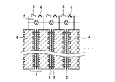
図1は本発明の一実施例による燃料電池スタックを示す部分断面図である。各単位燃料電池1は、電極構造体2と、その両側に配置されたカーボンペーパーからなるガス拡散層3,3と、その両側に配置された一対のセパレータ4,4とからなり、電極構造体2は高分子電解質膜と、その両面に形成された白金等の貴金属を含む電極層とからなる。電極構造体2と一対のガス拡散層3,3との組合せをセパレータ4と交互に積層することにより、燃料電池スタックが得られる。各セパレータ4の両面にはガス流路用の溝が形成されている。しかし、セパレータに冷却媒体流路を設ける場合、片面にガス流路用溝を形成し、他面に冷却媒体流路用溝を形成した一対のセパレータを冷却媒体流路用溝を内側にして貼り合わせて、使用するのが好ましい。
【0016】
電極構造体2を挟む一対のセパレータ4,4のうち、燃料ガス(水素ガス)側のセパレータ4は負極で、空気側のセパレータ4は正極であるので、隣接する一対のセパレータ4,4間に各単位燃料電池の起電力が生じる。従って各対のセパレータ4,4を直列に接続すれば、燃料電池スタック全体の起電力が得られる。各単位燃料電池が正しく作動しているか否かをチェックするために、電極構造体2を挟む一対のセパレータ4,4間に電圧計5が取り付けられている。
【0017】
本発明の燃料電池スタックは、各対のセパレータ4,4間に微小電流を流すことができる外部抵抗6が接続していることを特徴とする。外部抵抗6は電圧計5と並列であり、両者とも燃料電池スタックに取り付けられた電圧測定装置10内に収容されている。また複数の外部抵抗6同士は直列に接続している。
【0018】
図1の実施例では、外部抵抗6は常時接続であるので、その抵抗値は燃料電池スタックの出力特性に影響しないように十分に大きく設定する必要がある。具体的には、外部抵抗6の消費電力が燃料電池スタックの出力の1.5%以下、好ましくは0.5%以下になるように、外部抵抗6の抵抗値を設定するのが好ましい。
【0019】
図2は本発明の別の実施例による燃料電池スタックを示す斜視図である。この実施例では、単位燃料電池1全体を覆うようにセパレータ4の一側面に一本の外部抵抗7が付着している。図3は図2の燃料電池スタックの外部抵抗6の等価回路を示す。外部抵抗6の抵抗値を十分に大きく設定することにより、隣接するセパレータ4,4がショートすることはないが、残留燃料ガスによる開回路電圧が存在する場合には、残留ガスを消費させ、開回路電圧を低減するようにできる。具体的には、外部抵抗6の消費電力が燃料電池スタックの出力の1.5%以下、好ましくは0.5%以下になるように、外部抵抗6の抵抗値を設定するのが好ましい。
【0020】
図4は本発明のさらに別の実施例による燃料電池スタックを示す部分断面図である。この例の燃料電池スタックは、各外部抵抗6にスイッチ8が設けられている以外、図1に示す燃料電池スタックと同じである。従って、ここではスイッチ8の作用のみ説明することにする。
【0021】
例えば氷点以下の低温からの始動のような低温始動時に、非常に高い開回路電圧が発生するのを回避する場合、燃料ガスを燃料電池スタックに導入する前にスイッチ8を閉じて、外部抵抗6を各単位燃料電池1に接続しておき、燃料ガスを導入したら速やかにスイッチ8を開放する。外部抵抗6が各単位燃料電池1に接続することにより、低温始動時の開回路電圧が過剰に高くなるのを抑制することができる。
【0022】
燃料電池スタックの運転中はスイッチ8を開放したままにしておき、外部抵抗6により燃料電池スタックの出力特性が低下するのを防止する。また燃料電池スタックの運転停止後に燃料ガスが残留するが、スタック電圧を速やかに低下させるために、負荷の停止と同時にスイッチ8を閉じて外部抵抗8を接続させる。これにより電流が流れて残留燃料ガスは消費され、開回路電圧は速やかにゼロになる。次に始動するまでスイッチ8を閉じたままにしておき、外部抵抗6の接続状態を維持する。
【0023】
スイッチ8の作動を各単位燃料電池から外部回路に流れる電流レベルにより自動的に行うこともできる。例えば図5に示すように、単位燃料電池の平均セル電圧は電流密度の低下に応じて増大する傾向があるが、所定のレベルVcを超えるとセパレータ等の腐食が起こる。そのため、開回路電圧がVc以上になったらスイッチ8を閉じ、Vc未満になったらスイッチ8を開放するように設定するのが好ましい。電圧Vcにおける電流値Icから、外部抵抗6の抵抗値はVc/Ic(Ω)と設定することができる。
【0024】
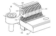
図6は、本発明により外部抵抗を組み込む燃料電池スタックの好ましい一例の全体構成を示す。この燃料電池スタックは、ケーシング(下部ケーシング132のみ示す)に支持された端子部材101により、セパレータ(図示せず)の電圧測定用端子(突起状端子)121と電圧測定装置10の電圧取得用端子123とが接続された状態を示す。燃料電池スタックの左右上端部には多数のセパレータの電圧測定用突起状端子121があり、各側面毎に多数の突起状端子121は複数のグループに分けられ、各グループの突起状端子121に接続された端子部材101は纏めて1つの絶縁性ケーシング130に収納される。
【0025】
図7〜9は本発明の燃料電池スタックに用いる端子部材101の一例を示す。図8に示すように端子部材101は一端で接合した一対の同じ形状の金属薄板片101a,101aからなり、各金属薄板片101a,101aは先端部111、弾性支持部112及び支点部113に相当する形状を有し、中央部101bで折り曲げられている。金属薄板片101a,101aの折り曲により、図10に示すように端子部材101の断面は実質的にコの字状となる。先端部111の間隙に電圧測定用端子121が挿入されるとともに、支点部113の間隙に電圧取得用端子123が挿入される。
【0026】
この実施例では、弾性支持部112は一対の外側に湾曲した幅の狭い帯部112a,112aからなる。各帯部112a,112aは幅が狭いのみならず湾曲しているので、積層した多数のセパレータに接合する場合、セパレータの積層方向のみならず積層方向に直交する二方向における変位に対しても、容易に変形することにより追随することができる。
【0027】
図8及び図9に示すように、支点部113は支点となる位置に開口部115を有する。この開口部115は電圧取得用端子123の開口部と整合され、ハト目118により回転自在にかつしっかりと接合される。図9(b) に示すように、ハト目118は支点部113の開口部115に挿入する筒部118aと、筒部118aを固定するためのフランジ部118bとからなる。ハト目118の筒部118aを開口部115に挿入した後、筒部118aの先端部を工具により圧開すると、ハト目118は開口部115に回転自在にかつしっかり固定される。ハト目118の開口部は端子部材101が回動するときの支点となり、電圧測定用端子121及び電圧取得用端子123に対して端子部材101を正確に位置決めすることができる。
【0028】
図11は電圧測定用端子121及び電圧取得用端子123に接続された端子部材101及び絶縁性ケーシング130の関係を詳細に示す。絶縁性ケーシング130はそれぞれプラスチック製の上部ケーシング131及び下部ケーシング132からなり、上部ケーシング131は電圧取得用端子123に接続された端子部材101の支点部113を支持し、下部ケーシング132は電圧測定用端子121に接続された端子部材101の先端部111を支持している。
【0029】
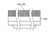
図12は絶縁性ケーシング130の側面図であり、図13は上部ケーシング131の側面図である。また図14は上部ケーシング131の平面図であり、図15は上部ケーシング131の背面図である。図13〜15から明らかなように、上部ケーシング131は、一体的に形成された本体部141と、本体部141の前部に一体的に形成され、隣接する端子部材101が接触するのを防止するための複数の幅の狭いスリット143を有するくし部142と、本体部141の後部に一体的に形成された突条部144とからなる。スリット143のピッチは接続すべき端子121,123の積層方向ピッチと同じである。突条部144はケーシング130を回転させるときにハンドルとして機能する。くし部142には長手方向の貫通孔146が設けられている。また本体部141には底面に開口するネジ穴148が設けられている。
【0030】
図16は下部ケーシング132の側面図であり、図17は平面図であり、図18は底面図であり、図19は背面図である。下部ケーシング132は、一体的に形成された本体部151と、本体部151の前部に一体的に形成され、隣接する端子部材101が接触するのを防止するための複数の幅の狭いスリット153を有するくし部152とからなる。本体部151には上部ケーシング131のネジ穴148に対応する位置に断面小判状の長孔156が設けられており、その長孔156の底面開口部はネジ頭部を受承する凹部158を有する。各くし部142,152のスリット143,153を精確に整列させるため、断面小判状の長孔156により上部ケーシング131に対する下部ケーシング132の固定位置を燃料電池スタックの積層方向に調節自在とする。
【0031】
図12に示すように、上部ケーシング131と下部ケーシング132とをネジ159で螺合すると、両者のくし部142,152は同じ側に位置し、それぞれのスリット143,153は整列する。その状態を上から見ると図20の平面図に示す通りである。
【0032】
図21は絶縁性ケーシング130を用いて多数の端子部材101を電圧測定用端子121及び電圧取得用端子123に一度に接続する方法を示す。まず図21(a) に示すように、個々の端子部材101を絶縁性ケーシング130のスリットに挿入した状態で、上部ケーシング131のくし部143を電圧取得用端子123の列と係合させ、各端子部材101の支点部113の断面コの字状間隙内に各電圧取得用端子123を挿入する。支点部113の開口部115と、電圧取得用端子123の開口部125と、上部ケーシング131の開口部146とを正確に整合させると、端子部材101を支持するケーシング130は開口部115,146を支点にして回転自在となる。
【0033】
次に図21(b) に示すように、端子部材101を支持するケーシング130を回転させて、下部ケーシング132のくし部152をセパレータの電圧測定用端子121と係合させ、各端子部材101の先端部111の断面コの字状間隙内に各電圧測定用端子121を挿入する。図21(c) は各端子部材101の先端部111の断面コの字状間隙内に各セパレータの電圧測定用端子121を完全に挿入した状態を示す。
【0034】
図11から明らかなように、各端子部材101の先端部111はセパレータの電圧測定用端子121を挟み込み、また支点部113は電圧測定装置10の電圧取得用端子123を挟み込み、もって各電圧測定用端子121と各田電圧取得用端子123とを接続する。端子部材101により電圧測定用端子121が電圧取得用端子123に接続した状態では、ケーシング130のくし部142,152の各くし片は隣接する端子部材101を絶縁するセパレータの役割をしている。
【0035】
【発明の効果】
本発明の燃料電池スタックは個々の単位燃料電池に高抵抗値の外部抵抗が接続されているので、単位燃料電池毎の残留ガス量のばらつきにより逆電圧がかかるのを防止することができる。特に低温始動時に単位燃料電池当たり1.35Vにも達する開回路電圧を約1Vに低減でき、電装系の耐電圧を低く設定することができる。また外部抵抗を常時接続しておくことにより開回路電圧をさらに低減することができるので、電装系の耐電圧をさらに低く設定することができる。また単位燃料電池の構成部品が高電圧にさらされて劣化するのを防止することもできる。
【0036】
また各外部抵抗にスイッチを設け、運転の始動及び停止時にスイッチを開閉することにより、運転(負荷の印加)時に余分な燃料ガスの消費を抑制し、燃料効率を向上させることができる。
【図面の簡単な説明】
【図1】 本発明の一実施例による燃料電池スタックを示す部分断面図である。
【図2】 本発明の別の実施例による燃料電池スタックを示す斜視図である。
【図3】 図2の燃料電池スタックの等価回路を示す部分断面図である。
【図4】 本発明のさらに別の実施例による燃料電池スタックを示す部分断面図である。
【図5】 燃料電池スタックの平均セル電圧と電流との関係を示すグラフである。
【図6】 絶縁性ケーシングを用いて端子部材をセパレータの電圧測定用端子及び電圧測定装置の電圧取得用端子に接続した状態を示す部分斜視図である。
【図7】 本発明の燃料電池スタックに使用するのに好ましい端子部材の一例を示す正面図である。
【図8】 図7の端子部材を折り目で展開した状態を示す展開図である。
【図9】 図7の端子部材の断面を示し、(a) は図7のA−A'断面図であり、(b) は端子部材に取り付けるハト目の概略図である。
【図10】 図7のB−B'断面図である。
【図11】 絶縁性ケーシングを用いて端子部材をセパレータの電圧測定用端子及び電圧測定装置の電圧取得用端子に接続した燃料電池スタックの詳細を示す部分拡大図であり、(a) は接続した状態を示し、(b) はその分解した状態を示す。
【図12】 端子部材を装着する絶縁性ケーシングを示す側面図である。
【図13】 上部ケーシングを示す側面図である。
【図14】 上部ケーシングを示す平面図である。
【図15】 上部ケーシングを示す背面図である。
【図16】 下部ケーシングを示す側面図である。
【図17】 下部ケーシングを示す平面図である。
【図18】 下部ケーシングを示す底面図である。
【図19】 下部ケーシングを示す背面図である。
【図20】 上部ケーシングと下部ケーシングを螺着してなるケーシングを示す平面図である。
【図21】 絶縁性ケーシングに装着した端子部材を電圧取得用端子及び電圧測定用端子に接続する方法を示す概略図であって、(a) は端子部材をケーシングの上方くし部ごと電圧取得用端子に接続した状態を示し、(b) は電圧取得用端子に係合した支点部のシャフトを中心にして、ケーシングに装着した端子部材を回転する状態を示し、(c) はケーシングに装着した端子部材の回転を完了して、端子部材をセパレータの下方くし部ごと電圧測定用端子に接続させた状態を示す。
【図22】 燃料電池スタックを構成するセル構造を示す分解正面図である。
【図23】 本発明を適用すべき燃料電池スタックを示す部分断面図である。
【符号の説明】
1・・・単位燃料電池
2・・・電極構造体
3・・・ガス拡散層
4・・・セパレータ
5・・・電圧計
6・・・外部抵抗
8・・・スイッチ
10・・・電圧測定装置
101・・・端子部材
101a・・・端子部材を一体的に構成する一対の金属薄板片の一方
101b・・・折り目
111・・・先端部
112・・・弾性支持部
112a・・・幅の狭い帯部
113・・・支点部
115・・・開口部
116・・・絶縁性シャフト
118・・・ハト目
121・・・セパレータの電圧測定用端子
123・・・電圧測定装置の電圧取得用端子
123a・・・端子部材の支点として作用する突起部
130,160・・・ケーシング
131,161・・・上部ケーシング
132,162・・・下部ケーシング
141,151・・・本体部
142,152・・・くし部
143,153・・・スリット
144・・・突条部
156・・・長孔
158・・・ネジ頭部を受承する凹部
159・・・ネジ[0001]
BACKGROUND OF THE INVENTION
The present invention relates to a fuel cell stack in which an excessive open circuit voltage is prevented from being generated at a low temperature start, and a component member is prevented from being corroded by an open circuit voltage due to a residual gas after operation is stopped.
[0002]
[Prior art and problems to be solved by the invention]
As shown in FIG. 22, the fuel cell stack includes an electrolyte membrane-electrode assembly (electrode structure) 2 having a structure in which
[0003]
In the fuel cell stack having such a structure, power is generated by reacting hydrogen gas with oxygen gas in the air, but when the fuel cell is stopped, the fuel gas remains in the fuel cell stack. Power generation does not stop immediately, but power generation continues in each unit fuel cell while residual fuel gas and air are present. Then, since an open circuit voltage is generated between the pair of
[0004]
Also, if the fuel cell stack is left in an open circuit voltage of about 1 V per unit cell, the particle size of the catalyst on the surface of the
[0005]
On the other hand, when starting at a low temperature below the freezing point, the open circuit voltage becomes a very high value when the gas is supplied. For example, an open circuit voltage of 1.35 V may be generated at a start of −30 ° C. This is because the
[0006]
As described above, the occurrence of a very high open circuit voltage is unavoidable, and in order to cope with this, it is necessary to set the withstand voltage of the electrical system high, and the cost of the fuel cell system increases accordingly.
[0007]
In order to solve the above problem, there is a method of purging the fuel gas remaining in the fuel cell stack with an inert gas after the operation is stopped. Nitrogen gas is usually used as the inert gas, but it is necessary to mount a tank for the inert gas in order to carry out this method. However, in order to mount an inert gas tank in an automobile or the like, not only a space for that purpose is required, but there is also a problem of management and replenishment of the remaining amount of inert gas, which complicates the entire fuel cell system. Therefore, purging with an inert gas is only used for an experimental level fuel cell stack and is difficult to put into practical use.
[0008]
There is also a method of reducing open circuit voltage by connecting a resistor to the terminals at both ends of the fuel cell stack and consuming current remaining in the fuel cell stack by flowing current. In this case, the resistor is connected in series to the plurality of unit fuel cells. However, the amount of fuel gas remaining in each unit fuel cell is not necessarily the same and is often non-uniform. Therefore, when a current is applied with a resistor connected, the amount of residual fuel gas is small and consumption is fast. A reverse voltage is applied to the unit fuel cell, which may damage the unit fuel cell.
[0009]
Accordingly, an object of the present invention is to effectively apply the open circuit voltage without damaging each unit fuel cell in order to solve the problem of open circuit voltage generation and corrosion caused by the fuel gas remaining after the operation is stopped. It is an object of the present invention to provide a fuel cell stack having a structure that can be reduced to a minimum.
[0010]
[Means for Solving the Problems]
As a result of diligent research in view of the above object, the present inventor, when the fuel gas remains in the fuel cell stack after operation stop, if the open circuit voltage thereby is reduced by an external resistance connected to each unit fuel cell The present inventors have found that the problem of unit fuel cell damage and corrosion can be solved, and have come up with the present invention.
[0011]
That is, in the fuel cell of the present invention in which a plurality of unit fuel cells are stacked via separators, an external resistor capable of passing a minute current is connected to each unit fuel cell , and on the outer periphery of each separator. Protruding terminals provided are connected to voltage acquisition terminals of voltage measuring devices attached to the fuel cell stack via individual terminal members, and each terminal member is an insulating casing having a plurality of partitions. It is characterized by being supported in an insulated state by individual partitions . With this structure, the open circuit voltage generated in each unit fuel cell can be reduced by individual external resistance, and the unit fuel cell can be prevented from being damaged or corroded.
[0012]
A switch is preferably mounted in series with the external resistor. With this structure, power loss due to external resistance can be prevented during operation of the fuel cell stack.
[0013]
In a preferred embodiment of the present invention, a voltage measuring device is attached to check whether each unit fuel cell of the fuel cell stack is operating correctly, but a protruding terminal provided on the outer periphery of each separator. Is connected to a voltage acquisition terminal of the voltage measurement device, and an external resistor provided in the voltage measurement device is connected to each voltage acquisition terminal so as to be in parallel with each voltmeter. The external resistors are preferably connected in series.
[0014]
In a preferred embodiment of the present invention, the protruding terminal of each separator and each voltage acquisition terminal of the voltage measuring device are connected via individual terminal members, and the individual terminal members are formed of an insulating casing having a plurality of partitions. It is supported in an insulated state by individual partitions. By inserting the terminal member into each gap of the insulating casing having a plurality of partitions, the terminal member can be positioned easily and reliably, and the contact of the plurality of terminal members can also be reliably prevented. . In addition, when the terminal member is joined to a large number of stacked separators, the terminal member has a shape that can easily follow the displacement in two directions perpendicular to the stacking direction as well as the separator stacking direction. It is preferable to have. Specifically, it is preferable that the terminal member has a narrow band shape that is curved outwardly.
[0015]
DETAILED DESCRIPTION OF THE INVENTION
FIG. 1 is a partial sectional view showing a fuel cell stack according to an embodiment of the present invention. Each
[0016]
Of the pair of
[0017]
The fuel cell stack of the present invention is characterized in that an
[0018]
In the embodiment of FIG. 1, since the
[0019]
FIG. 2 is a perspective view showing a fuel cell stack according to another embodiment of the present invention. In this embodiment, one
[0020]
FIG. 4 is a partial cross-sectional view showing a fuel cell stack according to still another embodiment of the present invention. The fuel cell stack of this example is the same as the fuel cell stack shown in FIG. 1 except that each
[0021]
In order to avoid the occurrence of a very high open circuit voltage during low temperature starting, for example starting from low temperatures below freezing, the
[0022]
During the operation of the fuel cell stack, the
[0023]
The operation of the
[0024]
FIG. 6 shows the overall configuration of a preferred example of a fuel cell stack incorporating external resistance according to the present invention. This fuel cell stack includes a voltage measurement terminal (protruding terminal) 121 of a separator (not shown) and a voltage acquisition terminal of the
[0025]
7 to 9 show an example of the
[0026]
In this embodiment, the
[0027]
As shown in FIGS. 8 and 9, the
[0028]
FIG. 11 shows the relationship between the
[0029]
FIG. 12 is a side view of the insulating
[0030]
16 is a side view of the
[0031]
As shown in FIG. 12, when the
[0032]
FIG. 21 shows a method of connecting a large number of
[0033]
Next, as shown in FIG. 21 (b), the
[0034]
As is clear from FIG. 11, the
[0035]
【The invention's effect】
In the fuel cell stack of the present invention, since an external resistance having a high resistance value is connected to each unit fuel cell, it is possible to prevent a reverse voltage from being applied due to variation in the amount of residual gas for each unit fuel cell. In particular, the open circuit voltage reaching 1.35 V per unit fuel cell at low temperature start can be reduced to about 1 V, and the withstand voltage of the electrical system can be set low. In addition, since the open circuit voltage can be further reduced by always connecting the external resistor, the withstand voltage of the electrical system can be set lower. It is also possible to prevent the component parts of the unit fuel cell from being deteriorated by being exposed to a high voltage.
[0036]
In addition, by providing a switch for each external resistor and opening and closing the switch at the start and stop of operation, consumption of excess fuel gas during operation (load application) can be suppressed, and fuel efficiency can be improved.
[Brief description of the drawings]
FIG. 1 is a partial cross-sectional view showing a fuel cell stack according to an embodiment of the present invention.
FIG. 2 is a perspective view showing a fuel cell stack according to another embodiment of the present invention.
3 is a partial cross-sectional view showing an equivalent circuit of the fuel cell stack of FIG. 2. FIG.
FIG. 4 is a partial cross-sectional view showing a fuel cell stack according to still another embodiment of the present invention.
FIG. 5 is a graph showing the relationship between the average cell voltage and current of the fuel cell stack.
FIG. 6 is a partial perspective view showing a state in which a terminal member is connected to a voltage measurement terminal of a separator and a voltage acquisition terminal of a voltage measurement device using an insulating casing.
FIG. 7 is a front view showing an example of a terminal member preferable for use in the fuel cell stack of the present invention.
8 is a development view showing a state in which the terminal member of FIG. 7 is developed by a crease. FIG.
9 is a cross-sectional view of the terminal member of FIG. 7, wherein (a) is a cross-sectional view taken along line AA ′ of FIG. 7, and (b) is a schematic view of eyelets attached to the terminal member.
10 is a cross-sectional view taken along the line BB ′ of FIG.
FIG. 11 is a partially enlarged view showing details of a fuel cell stack in which a terminal member is connected to a voltage measurement terminal of a separator and a voltage acquisition terminal of a voltage measurement device using an insulating casing, and (a) is a connection diagram; The state is shown, and (b) shows its disassembled state.
FIG. 12 is a side view showing an insulating casing to which a terminal member is attached.
FIG. 13 is a side view showing the upper casing.
FIG. 14 is a plan view showing an upper casing.
FIG. 15 is a rear view showing the upper casing.
FIG. 16 is a side view showing the lower casing.
FIG. 17 is a plan view showing a lower casing.
FIG. 18 is a bottom view showing the lower casing.
FIG. 19 is a rear view showing the lower casing.
FIG. 20 is a plan view showing a casing formed by screwing an upper casing and a lower casing.
FIG. 21 is a schematic diagram showing a method of connecting a terminal member mounted on an insulating casing to a voltage acquisition terminal and a voltage measurement terminal, wherein (a) is for acquiring a voltage along with the upper comb part of the casing. (B) shows the state of rotating the terminal member attached to the casing around the shaft of the fulcrum part engaged with the voltage acquisition terminal, and (c) shows the state attached to the casing. The state where the rotation of the terminal member is completed and the terminal member is connected to the voltage measuring terminal together with the lower comb portion of the separator is shown.
FIG. 22 is an exploded front view showing a cell structure constituting the fuel cell stack.
FIG. 23 is a partial cross-sectional view showing a fuel cell stack to which the present invention is to be applied.
[Explanation of symbols]
DESCRIPTION OF
10 ... Voltage measuring device
101 ... Terminal member
101a... One of a pair of thin metal plate pieces integrally constituting the terminal member
101b ・ ・ ・ Fold
111 ・ ・ ・ Tip
112 ・ ・ ・ Elastic support
112a ・ ・ ・ Narrow strip
113 ... fulcrum
115 ・ ・ ・ Opening
116 ・ ・ ・ Insulating shaft
118 ...
121 ・ ・ ・ Separator voltage measurement terminal
123 ・ ・ ・ Voltage acquisition terminal of voltage measuring device
123a ... Projection that acts as a fulcrum for the terminal
130, 160 ... casing
131, 161 ... Upper casing
132,162 ... Lower casing
141, 151 ... body part
142, 152 ... Comb
143, 153 ... Slit
144 ... ridge
156 ... Long hole
158 ... recess for receiving screw head
159 ... Screw
Claims (4)
Priority Applications (6)
| Application Number | Priority Date | Filing Date | Title |
|---|---|---|---|
| JP2001307937A JP3895960B2 (en) | 2001-10-03 | 2001-10-03 | Fuel cell stack |
| EP02772972A EP1450429B1 (en) | 2001-10-03 | 2002-10-03 | Fuel cell stack |
| US10/491,836 US7226678B2 (en) | 2001-10-03 | 2002-10-03 | Fuel cell stack |
| CA2462696A CA2462696C (en) | 2001-10-03 | 2002-10-03 | Fuel cell stack with decreased open circuit voltage |
| PCT/JP2002/010321 WO2003032423A1 (en) | 2001-10-03 | 2002-10-03 | Fuel cell stack |
| US11/716,449 US7691506B2 (en) | 2001-10-03 | 2007-03-09 | Fuel cell stack |
Applications Claiming Priority (1)
| Application Number | Priority Date | Filing Date | Title |
|---|---|---|---|
| JP2001307937A JP3895960B2 (en) | 2001-10-03 | 2001-10-03 | Fuel cell stack |
Publications (2)
| Publication Number | Publication Date |
|---|---|
| JP2003115305A JP2003115305A (en) | 2003-04-18 |
| JP3895960B2 true JP3895960B2 (en) | 2007-03-22 |
Family
ID=19127316
Family Applications (1)
| Application Number | Title | Priority Date | Filing Date |
|---|---|---|---|
| JP2001307937A Expired - Fee Related JP3895960B2 (en) | 2001-10-03 | 2001-10-03 | Fuel cell stack |
Country Status (5)
| Country | Link |
|---|---|
| US (2) | US7226678B2 (en) |
| EP (1) | EP1450429B1 (en) |
| JP (1) | JP3895960B2 (en) |
| CA (1) | CA2462696C (en) |
| WO (1) | WO2003032423A1 (en) |
Families Citing this family (29)
| Publication number | Priority date | Publication date | Assignee | Title |
|---|---|---|---|---|
| JP4904661B2 (en) * | 2002-11-21 | 2012-03-28 | 株式会社デンソー | Fuel cell system |
| JP2004355948A (en) * | 2003-05-29 | 2004-12-16 | Sony Corp | Fuel cell system |
| WO2005078844A1 (en) * | 2004-02-12 | 2005-08-25 | Toyota Jidosha Kabushiki Kaisha | Fuel battery system and method for removing residual fuel gas |
| US7972749B2 (en) * | 2004-06-24 | 2011-07-05 | GM Global Technology Operations LLC | Low voltage power tap on high voltage stack |
| JP2006093092A (en) * | 2004-08-23 | 2006-04-06 | Nissan Motor Co Ltd | Fuel cell |
| JP4653467B2 (en) * | 2004-11-29 | 2011-03-16 | 本田技研工業株式会社 | Fuel cell system |
| US7488551B2 (en) * | 2004-12-28 | 2009-02-10 | Ballard Power Systems Inc. | Integrated current collector and electrical component plate for a fuel cell stack |
| US20060246331A1 (en) * | 2005-04-29 | 2006-11-02 | Steinbroner Matthew P | Partitioned fuel cell stacks and fuel cell systems including the same |
| JP2007317516A (en) | 2006-05-26 | 2007-12-06 | Canon Inc | Fuel cell and fuel cell device |
| JP2008047537A (en) * | 2006-08-17 | 2008-02-28 | Samsung Sdi Co Ltd | Fuel battery system and fuel battery operation method |
| JP4848967B2 (en) * | 2007-01-30 | 2011-12-28 | トヨタ自動車株式会社 | Fuel cell system |
| JP2008300296A (en) * | 2007-06-01 | 2008-12-11 | Toyota Motor Corp | Fuel cell system |
| KR100906902B1 (en) | 2007-07-18 | 2009-07-08 | 현대자동차주식회사 | Safety system of fuel cell stack and method for the same |
| JP4337104B2 (en) * | 2007-12-19 | 2009-09-30 | トヨタ自動車株式会社 | Fuel cell system |
| JP5307441B2 (en) * | 2008-04-22 | 2013-10-02 | 本田技研工業株式会社 | Fuel cell stack |
| CN102356508B (en) * | 2009-03-16 | 2016-04-13 | 永备电池有限公司 | There is the oxygen consumption battery pack of the high rate capability of improvement |
| WO2010144041A1 (en) * | 2009-06-09 | 2010-12-16 | Myfc Ab | Fuel cell device and method of operating the same |
| JP2011003477A (en) * | 2009-06-19 | 2011-01-06 | Fuji Electric Holdings Co Ltd | Solid polymer fuel cell |
| FR2951583B1 (en) | 2009-10-19 | 2012-01-27 | Commissariat Energie Atomique | PREVENTING THE CORROSION OF A FUEL CELL |
| US9065096B2 (en) | 2011-02-24 | 2015-06-23 | Samsung Sdi Co., Ltd. | Fuel cell stack |
| AT512622B1 (en) * | 2012-02-15 | 2016-09-15 | Fronius Int Gmbh | METHOD AND DEVICE FOR OPERATING A FUEL CELL UNIT |
| KR101337937B1 (en) | 2012-05-04 | 2013-12-09 | 현대자동차주식회사 | Connector measuring for cell voltage of fuel cell stack in vehicle |
| GB2521401B (en) * | 2013-12-18 | 2021-02-10 | Intelligent Energy Ltd | Connector system for a fuel cell stack assembly |
| CN107949944B (en) * | 2015-01-21 | 2021-04-13 | 美国电化学动力公司 | Self-heating fuel cell system |
| US10523003B2 (en) | 2017-01-30 | 2019-12-31 | Cummins Enterprise Inc. | Auxiliary power circuit and method of use |
| DE102018211988A1 (en) * | 2018-07-18 | 2020-01-23 | Siemens Mobility GmbH | Fuel cell with protection against open circuit voltage |
| DE102019215895A1 (en) * | 2019-10-16 | 2021-04-22 | Robert Bosch Gmbh | Method for commissioning a fuel cell stack |
| KR102308789B1 (en) * | 2019-11-08 | 2021-10-05 | 현대모비스 주식회사 | System and method for sensing fuel cell of vehicle |
| US11664513B2 (en) | 2019-11-08 | 2023-05-30 | Hyundai Mobis Co., Ltd. | System and method for sensing fuel cell of vehicle |
Family Cites Families (15)
| Publication number | Priority date | Publication date | Assignee | Title |
|---|---|---|---|---|
| JPS60189871A (en) * | 1984-03-09 | 1985-09-27 | Hitachi Ltd | Operation of fuel cell |
| JPH0793147B2 (en) | 1987-01-23 | 1995-10-09 | 三菱電機株式会社 | Fuel cell power generation system |
| JPS6471073A (en) * | 1987-09-09 | 1989-03-16 | Hitachi Maxell | Storing method for room temperature type acidic methanol fuel cell |
| US5023150A (en) * | 1988-08-19 | 1991-06-11 | Fuji Electric Co., Ltd. | Method and apparatus for controlling a fuel cell |
| JPH09199151A (en) | 1996-01-12 | 1997-07-31 | Toshiba Corp | Fuel cell and its catalytic processing method |
| JPH10223248A (en) | 1997-02-05 | 1998-08-21 | Fuji Electric Co Ltd | Discharging device for fuel cell |
| US6025083A (en) * | 1998-02-25 | 2000-02-15 | Siemens Westinghouse Power Corporation | Fuel cell generator energy dissipator |
| US6093500A (en) | 1998-07-28 | 2000-07-25 | International Fuel Cells Corporation | Method and apparatus for operating a fuel cell system |
| JP4366744B2 (en) | 1999-01-27 | 2009-11-18 | アイシン精機株式会社 | Fuel cell stack and fuel cell system |
| DE19921675A1 (en) * | 1999-05-11 | 2000-11-16 | Hornung Hans Georg | Method for acquiring parameters and measured quantities of battery packs and the like |
| US6527943B1 (en) * | 1999-11-08 | 2003-03-04 | Ballard Power Systems, Inc. | Fuel cell concentration sensor |
| US6724194B1 (en) * | 2000-06-30 | 2004-04-20 | Ballard Power Systems Inc. | Cell voltage monitor for a fuel cell stack |
| US6641946B2 (en) * | 2001-02-15 | 2003-11-04 | Siemens Westinghouse Power Corporation | Fuel dissipater for pressurized fuel cell generators |
| JP4491166B2 (en) * | 2001-04-20 | 2010-06-30 | 本田技研工業株式会社 | Connection terminal member for cell voltage measurement of a fuel cell |
| US6913845B2 (en) | 2002-10-28 | 2005-07-05 | Utc Fuel Cells, Llc | Reducing fuel cell cathode potential during startup and shutdown |
-
2001
- 2001-10-03 JP JP2001307937A patent/JP3895960B2/en not_active Expired - Fee Related
-
2002
- 2002-10-03 CA CA2462696A patent/CA2462696C/en not_active Expired - Fee Related
- 2002-10-03 US US10/491,836 patent/US7226678B2/en not_active Expired - Lifetime
- 2002-10-03 EP EP02772972A patent/EP1450429B1/en not_active Expired - Lifetime
- 2002-10-03 WO PCT/JP2002/010321 patent/WO2003032423A1/en active Application Filing
-
2007
- 2007-03-09 US US11/716,449 patent/US7691506B2/en not_active Expired - Fee Related
Also Published As
| Publication number | Publication date |
|---|---|
| EP1450429A1 (en) | 2004-08-25 |
| US7226678B2 (en) | 2007-06-05 |
| JP2003115305A (en) | 2003-04-18 |
| US7691506B2 (en) | 2010-04-06 |
| EP1450429A4 (en) | 2007-08-22 |
| WO2003032423A1 (en) | 2003-04-17 |
| CA2462696C (en) | 2010-03-30 |
| US20070154749A1 (en) | 2007-07-05 |
| EP1450429B1 (en) | 2012-02-29 |
| US20050042492A1 (en) | 2005-02-24 |
| CA2462696A1 (en) | 2003-04-17 |
Similar Documents
| Publication | Publication Date | Title |
|---|---|---|
| JP3895960B2 (en) | Fuel cell stack | |
| JP5061698B2 (en) | Power storage device | |
| KR100801635B1 (en) | Member for Measurement of Cell Voltage And Temperature in Battery Pack | |
| EP2418725B1 (en) | Battery system, vehicle, and battery mounted device | |
| JP2581082Y2 (en) | Battery device | |
| US5911947A (en) | Fan-folded polymer-electrolyte cell | |
| US6858345B2 (en) | Wound bipolar lithium polymer batteries | |
| JPH11339828A (en) | Fuel cell stack with cell voltage measuring terminal | |
| JP6144180B2 (en) | Fuel cell humidification control method | |
| KR20110056698A (en) | Secondary battery and circuit board assembly suitable for the same | |
| JP2010015914A (en) | Battery device, vehicle and temperature information obtaining unit | |
| JP5765062B2 (en) | Battery, power supply device, battery driving system, and method for detecting expansion of battery | |
| JP3674921B2 (en) | Fuel cell | |
| JP2009272113A (en) | Electricity storage device | |
| Mohamedi et al. | In situ analysis of high temperature characteristics of prismatic polymer lithium-ion batteries | |
| JP2598014B2 (en) | Crossover detection method for stacked fuel cells | |
| KR100551886B1 (en) | Pouch type Lithium secondary battery | |
| CN218215429U (en) | Battery, battery management system and device using the battery as power supply | |
| JP2002042904A (en) | Terminal mechanism for secondary battery charger/ discharger | |
| JP7520561B2 (en) | Energy storage element | |
| CN221466850U (en) | Connector, battery pack and electricity utilization device | |
| US11796503B2 (en) | Water detecting device and method of water detection | |
| US20110117429A1 (en) | Galvanic cell with improved lifetime | |
| JP2024088622A (en) | Battery with optimized temperature controllability | |
| CN115236402A (en) | Method for measuring stack film resistance of proton exchange film fuel cell |
Legal Events
| Date | Code | Title | Description |
|---|---|---|---|
| A131 | Notification of reasons for refusal |
Free format text: JAPANESE INTERMEDIATE CODE: A131 Effective date: 20050706 |
|
| A521 | Written amendment |
Free format text: JAPANESE INTERMEDIATE CODE: A523 Effective date: 20050817 |
|
| A131 | Notification of reasons for refusal |
Free format text: JAPANESE INTERMEDIATE CODE: A131 Effective date: 20061025 |
|
| A521 | Written amendment |
Free format text: JAPANESE INTERMEDIATE CODE: A523 Effective date: 20061110 |
|
| TRDD | Decision of grant or rejection written | ||
| A01 | Written decision to grant a patent or to grant a registration (utility model) |
Free format text: JAPANESE INTERMEDIATE CODE: A01 Effective date: 20061206 |
|
| A61 | First payment of annual fees (during grant procedure) |
Free format text: JAPANESE INTERMEDIATE CODE: A61 Effective date: 20061215 |
|
| R150 | Certificate of patent or registration of utility model |
Ref document number: 3895960 Country of ref document: JP Free format text: JAPANESE INTERMEDIATE CODE: R150 Free format text: JAPANESE INTERMEDIATE CODE: R150 |
|
| FPAY | Renewal fee payment (event date is renewal date of database) |
Free format text: PAYMENT UNTIL: 20091222 Year of fee payment: 3 |
|
| FPAY | Renewal fee payment (event date is renewal date of database) |
Free format text: PAYMENT UNTIL: 20101222 Year of fee payment: 4 |
|
| FPAY | Renewal fee payment (event date is renewal date of database) |
Free format text: PAYMENT UNTIL: 20101222 Year of fee payment: 4 |
|
| FPAY | Renewal fee payment (event date is renewal date of database) |
Free format text: PAYMENT UNTIL: 20111222 Year of fee payment: 5 |
|
| FPAY | Renewal fee payment (event date is renewal date of database) |
Free format text: PAYMENT UNTIL: 20111222 Year of fee payment: 5 |
|
| FPAY | Renewal fee payment (event date is renewal date of database) |
Free format text: PAYMENT UNTIL: 20121222 Year of fee payment: 6 |
|
| FPAY | Renewal fee payment (event date is renewal date of database) |
Free format text: PAYMENT UNTIL: 20131222 Year of fee payment: 7 |
|
| LAPS | Cancellation because of no payment of annual fees |