JP3895347B2 - Tire deformation amount calculation method and tire deformation amount calculation device - Google Patents
Tire deformation amount calculation method and tire deformation amount calculation device Download PDFInfo
- Publication number
- JP3895347B2 JP3895347B2 JP2004335417A JP2004335417A JP3895347B2 JP 3895347 B2 JP3895347 B2 JP 3895347B2 JP 2004335417 A JP2004335417 A JP 2004335417A JP 2004335417 A JP2004335417 A JP 2004335417A JP 3895347 B2 JP3895347 B2 JP 3895347B2
- Authority
- JP
- Japan
- Prior art keywords
- tire
- acceleration
- deformation amount
- data
- region
- Prior art date
- Legal status (The legal status is an assumption and is not a legal conclusion. Google has not performed a legal analysis and makes no representation as to the accuracy of the status listed.)
- Expired - Fee Related
Links
- 238000004364 calculation method Methods 0.000 title claims description 69
- 230000001133 acceleration Effects 0.000 claims description 193
- 238000005259 measurement Methods 0.000 claims description 71
- 238000006073 displacement reaction Methods 0.000 claims description 42
- 238000005096 rolling process Methods 0.000 claims description 41
- 238000000034 method Methods 0.000 claims description 24
- 238000012545 processing Methods 0.000 claims description 20
- 230000010354 integration Effects 0.000 claims description 15
- 230000005484 gravity Effects 0.000 claims description 5
- 239000000284 extract Substances 0.000 claims description 4
- 230000004069 differentiation Effects 0.000 claims description 2
- 230000006870 function Effects 0.000 description 19
- 230000002093 peripheral effect Effects 0.000 description 10
- 230000008859 change Effects 0.000 description 6
- 230000008569 process Effects 0.000 description 4
- 238000009499 grossing Methods 0.000 description 3
- 239000004065 semiconductor Substances 0.000 description 3
- 238000004088 simulation Methods 0.000 description 3
- 230000009466 transformation Effects 0.000 description 3
- 235000013339 cereals Nutrition 0.000 description 2
- 238000010586 diagram Methods 0.000 description 2
- 230000000737 periodic effect Effects 0.000 description 2
- 238000005070 sampling Methods 0.000 description 2
- 230000005540 biological transmission Effects 0.000 description 1
- 238000001514 detection method Methods 0.000 description 1
- 230000000694 effects Effects 0.000 description 1
- 238000012986 modification Methods 0.000 description 1
- 230000004048 modification Effects 0.000 description 1
- 238000010606 normalization Methods 0.000 description 1
- NJPPVKZQTLUDBO-UHFFFAOYSA-N novaluron Chemical compound C1=C(Cl)C(OC(F)(F)C(OC(F)(F)F)F)=CC=C1NC(=O)NC(=O)C1=C(F)C=CC=C1F NJPPVKZQTLUDBO-UHFFFAOYSA-N 0.000 description 1
- 238000001228 spectrum Methods 0.000 description 1
- 238000013519 translation Methods 0.000 description 1
- 238000001845 vibrational spectrum Methods 0.000 description 1
Images


Classifications
-
- G—PHYSICS
- G01—MEASURING; TESTING
- G01B—MEASURING LENGTH, THICKNESS OR SIMILAR LINEAR DIMENSIONS; MEASURING ANGLES; MEASURING AREAS; MEASURING IRREGULARITIES OF SURFACES OR CONTOURS
- G01B21/00—Measuring arrangements or details thereof, where the measuring technique is not covered by the other groups of this subclass, unspecified or not relevant
- G01B21/32—Measuring arrangements or details thereof, where the measuring technique is not covered by the other groups of this subclass, unspecified or not relevant for measuring the deformation in a solid
Landscapes
- Physics & Mathematics (AREA)
- General Physics & Mathematics (AREA)
- Tires In General (AREA)
- Length Measuring Devices With Unspecified Measuring Means (AREA)
Description
本発明は、路面を転動するタイヤの所定の部位における周上の変形量を、タイヤの所定の部位に設けた加速度センサ等からの加速度の計測データを用いて算出するタイヤ変形量算出方法及びタイヤ変形量算出装置に関し、特に、路面を転動するタイヤのトレッド部の周上の変形量を、タイヤのトレッド部に設けた加速度センサ等からの加速度の計測データを用いて算出するタイヤ変形量算出方法及びタイヤ変形量算出装置に関する。 The present invention relates to a tire deformation amount calculating method for calculating a circumferential deformation amount at a predetermined portion of a tire rolling on a road surface by using acceleration measurement data from an acceleration sensor or the like provided at the predetermined portion of the tire, and With regard to a tire deformation amount calculation device, in particular, a tire deformation amount for calculating a deformation amount on the circumference of a tread portion of a tire rolling on a road surface by using acceleration measurement data from an acceleration sensor or the like provided on the tire tread portion. The present invention relates to a calculation method and a tire deformation amount calculation device.
従来より、転動中のタイヤのトレッド部における周上の変形量の分布(タイヤのトレッド部の変形形状)や接地長は、有限要素モデルを用いて転動中のタイヤのシミュレーションを行って取得されてきた。この取得方法では、有限要素モデルの作成に要する時間やシミュレーションの演算時間の点から短時間にトレッド部の変形形態や接地長を取得することができなかった。このため、転動中の接地長や変形形状を非転動中の接地長やタイヤの変形形状で代用していた。
しかし、転動中のタイヤの接地長や接地形状に影響を与えるタイヤの周上の変形形状は、タイヤ性能に極めて影響を与えるものであるため、転動中のタイヤの計測により接地長や変形形状を取得し、タイヤ性能を判断することが従来より求められていた。
Conventionally, the distribution of deformation on the circumference of the tread portion of the rolling tire (the deformation shape of the tread portion of the tire) and the contact length are obtained by simulating the rolling tire using a finite element model. It has been. In this acquisition method, the deformation form and the contact length of the tread portion cannot be acquired in a short time in terms of the time required for creating the finite element model and the calculation time of the simulation. For this reason, the contact length and deformation shape during rolling are replaced with the contact length and tire deformation shape during non-rolling.
However, because the deformation shape on the circumference of the tire that affects the contact length and contact shape of the rolling tire has a significant effect on the tire performance, the contact length and deformation can be determined by measuring the rolling tire. It has been conventionally required to acquire the shape and judge the tire performance.
一方、下記特許文献1〜3では、加速度センサをタイヤに取り付けて、転動中のタイヤの加速度の計測データを取得し、この取得した計測データからパワースペクトルや振動スペクトルを求めて転動中の路面状態を推定する方法、またラジアル方向の加速度の計測データからトレッド部が路面に接触するタイミングを判定する方法等が開示されている。
しかし、特許文献1〜3では、加速度の計測データを用いて路面状態を推定できるものの、この計測データから、転動中のタイヤの変形形状や接地長を算出することができない。
On the other hand, in
However, in
そこで、本発明は、路面を転動する際のタイヤの変形量を、タイヤの所定の部位における加速度の計測データを用いて算出するタイヤ変形量算出方法及びタイヤ変形量算出装置、特に、路面を転動する際のタイヤの変形量を、タイヤのトレッド部における加速度の計測データを用いて算出するタイヤ変形量算出方法及びタイヤ変形量算出装置を提供することを目的とする。 Therefore, the present invention provides a tire deformation amount calculation method and a tire deformation amount calculation device for calculating a deformation amount of a tire when rolling on a road surface using measurement data of acceleration at a predetermined portion of the tire, in particular, a road surface. It is an object of the present invention to provide a tire deformation amount calculation method and a tire deformation amount calculation device for calculating a deformation amount of a tire when rolling using measurement data of acceleration in a tread portion of the tire.
上記目的を達成するために、本発明は、路面をタイヤが転動する際のタイヤの変形量を算出するタイヤ変形量算出方法であって、転動中のタイヤの所定の部位に加速度センサを配置して得られる、少なくともタイヤ1回転分の加速度の計測データを取得する取得ステップと、取得した加速度の計測データから背景成分を除去することで、タイヤの変形に基づく加速度の時系列データを抽出する信号処理ステップと、前記タイヤの変形に基づく加速度の時系列データに対して2階の時間積分を行って変位データを求めることにより、タイヤの前記所定の部位における変形量を算出する変形量算出ステップと、を有することを特徴とするタイヤ変形量算出方法を提供する。 In order to achieve the above object, the present invention provides a tire deformation amount calculation method for calculating a deformation amount of a tire when the tire rolls on a road surface, and includes an acceleration sensor at a predetermined portion of the rolling tire. An acquisition step for acquiring acceleration measurement data for at least one rotation of the tire obtained by arranging and extracting time-series data of acceleration based on tire deformation by removing background components from the acquired acceleration measurement data A deformation amount calculation for calculating a deformation amount at the predetermined portion of the tire by obtaining a displacement data by performing second-order time integration on the time series data of acceleration based on the deformation of the tire And a tire deformation amount calculation method comprising: steps.
なお、前記所定の部位は前記タイヤのトレッド部であり、前記取得ステップではタイヤのトレッド部の加速度を取得し、前記変形量算出ステップではタイヤのトレッド部における変形量を算出することが好ましい。その際、前記タイヤのトレッド部の周上の領域を、路面と接する接地領域を含む第1の領域とこれ以外の第2の領域とに分け、前記信号処理ステップでは、前記第2の領域の加速度の計測データを近似することにより、前記第1の領域上及び前記第2の領域上で定められる第1の近似曲線を算出し、前記取得ステップで取得した加速度の波形からこの第1の近似曲線を差し引くことにより、前記第1の領域及び前記第2の領域におけるタイヤの変形量に基づく加速度の時系列データを抽出することが好ましい。 It is preferable that the predetermined portion is a tread portion of the tire, an acceleration of the tread portion of the tire is acquired in the acquisition step, and a deformation amount in the tread portion of the tire is calculated in the deformation amount calculation step. At that time, the region on the circumference of the tread portion of the tire is divided into a first region including a ground contact region in contact with a road surface and a second region other than this, and in the signal processing step, By approximating measurement data of acceleration, a first approximate curve defined on the first area and the second area is calculated, and the first approximation is obtained from the acceleration waveform acquired in the acquisition step. It is preferable to extract time series data of acceleration based on the amount of deformation of the tire in the first region and the second region by subtracting a curve .
また、前記第1の近似曲線は、前記第2の領域中に複数個の節点を設けて、前記第2の領域に加えて前記第1の領域における前記加速度の計測データを近似した曲線であることが好ましい。前記第1の近似曲線は、前記第1の領域の加速度の時系列データと前記第2の領域の加速度の時系列データに重み係数を与えて算出したものであり、しかも、前記第1の領域の加速度の時系列データに比べて前記第2の領域の加速度の時系列データの重み係数を大きくして、前記第1の領域及び前記第2の領域における前記加速度の時系列データを近似した曲線であることが好ましい。 The first approximate curve is a curve obtained by providing a plurality of nodes in the second area and approximating the acceleration measurement data in the first area in addition to the second area. It is preferable. The first approximate curve is calculated by giving a weighting factor to the time series data of acceleration of the first area and the time series data of acceleration of the second area, and the first area A curve that approximates the time series data of the acceleration in the first area and the second area by increasing the weighting coefficient of the time series data of the acceleration in the second area as compared to the time series data of the acceleration of It is preferable that
また、前記第2の領域は、前記タイヤの接地領域の中心位置を基準として周方向の角度の絶対値が少なくとも60度以上の領域であることが好ましい。 The second region is preferably a region where the absolute value of the angle in the circumferential direction is at least 60 degrees or more with reference to the center position of the ground contact region of the tire.
また、前記タイヤのトレッド部の周上の領域を、路面との接地領域を含む第3の領域とこれ以外の第4の領域とに分け、前記変形量算出ステップでは、前記第4の領域の前記変位データを近似することにより、前記第1の領域上及び前記第2の領域上で定められる第2の近似曲線を算出し、前記変位データの波形からこの第2の近似曲線を差し引くことにより、タイヤの変形量を算出することが好ましい。また、前記第2の近似曲線は、前記第4の領域中に複数個の節点を設けて、前記第3の領域及び前記第4の領域における前記変位データを近似した曲線であることが好ましい。
さらに、前記第2の近似曲線は、前記第3の領域の前記変位データと前記第4の領域の前記変位データに重み係数を与えて最小二乗法により算出したものであり、しかも、前記第3の領域の変位データに比べて前記第4の領域の変位データの重み係数を大きくして、前記第3の領域及び前記第4の領域における変位データを近似した曲線であることが好ましい。
In addition, the region on the circumference of the tread portion of the tire is divided into a third region including a contact region with the road surface and a fourth region other than this, and in the deformation amount calculating step, By approximating the displacement data, a second approximate curve determined on the first area and the second area is calculated, and the second approximate curve is subtracted from the waveform of the displacement data. It is preferable to calculate the deformation amount of the tire. The second approximate curve is preferably a curve obtained by providing a plurality of nodes in the fourth region and approximating the displacement data in the third region and the fourth region.
Further, the second approximate curve is calculated by a least square method by giving a weighting factor to the displacement data of the third region and the displacement data of the fourth region, and It is preferable that the weighting coefficient of the displacement data of the fourth region is larger than the displacement data of the region, and the curve approximates the displacement data in the third region and the fourth region.
前記加速度の計測データは、例えば、前記タイヤのトレッド部に加速度センサを配置して得られるデータである。
また、前記加速度の計測データは、タイヤの周方向に対して直交するラジアル方向の加速度のデータ、タイヤの周方向の加速度のデータ、及びタイヤの幅方向の加速度のデータのうち、少なくとも1つであることが好ましい。
また、前記加速度の計測データは、タイヤの周方向に対して直交するラジアル方向の加速度のデータ、または、このラジアル方向の加速度のデータに加えてタイヤの周方向の加速度のデータを含むものであり、前記信号処理ステップでは、前記背景成分として、タイヤの転動中の遠心力の加速度成分および重力加速度成分を少なくとも除去することも好ましい。
また、前記加速度の計測データは、タイヤの周方向に対して直交するラジアル方向の加速度のデータ及びタイヤの周方向の加速度のデータの少なくとも一方のデータであり、さらに、前記タイヤの変形量は、タイヤのトレッド部のラジアル方向及び周方向の変形量、若しくはラジアル方向の変形量であり、この変形量から前記タイヤの転動中の接地長を算出することが好ましい。
The acceleration measurement data is data obtained by arranging an acceleration sensor in the tread portion of the tire, for example.
The acceleration measurement data may be at least one of radial acceleration data orthogonal to the tire circumferential direction, tire circumferential acceleration data, and tire width acceleration data. Preferably there is.
Further, the acceleration measurement data includes radial acceleration data orthogonal to the tire circumferential direction, or tire radial acceleration data in addition to the radial acceleration data. In the signal processing step, it is also preferable to remove at least an acceleration component and a gravity acceleration component of centrifugal force during rolling of the tire as the background component.
The acceleration measurement data is at least one of radial acceleration data orthogonal to the tire circumferential direction and tire circumferential acceleration data, and the tire deformation amount is: It is the amount of deformation in the radial direction and circumferential direction of the tread portion of the tire, or the amount of deformation in the radial direction, and it is preferable to calculate the contact length during rolling of the tire from this amount of deformation.
さらに、本発明は、路面上をタイヤが転動する際のタイヤの変形量を算出するタイヤ変形量算出装置であって、転動中のタイヤの所定の部位に加速度センサを配置して得られる、少なくともタイヤ1回転分の加速度の計測データを取得するデータ取得部と、取得した加速度の計測データから背景成分を除去することで、タイヤの変形に基づく加速度の時系列データを抽出する信号処理部と、前記タイヤの変形に基づく加速度の時系列データに対して2階の時間積分を行って変位データを求めることにより、タイヤの所定の部位における変形量を算出する変形量算出部と、を有することを特徴とするタイヤ変形量算出装置を提供する。 Furthermore, the present invention is a tire deformation amount calculation device for calculating a deformation amount of a tire when the tire rolls on a road surface, and is obtained by arranging an acceleration sensor at a predetermined portion of the rolling tire. a data acquisition unit for acquiring measurement data of acceleration of at least the tire one revolution, by removing the background component from the measurement data of the acquired acceleration signal processing unit for extracting time series data of acceleration due to tire deformation And a deformation amount calculation unit that calculates a deformation amount at a predetermined portion of the tire by performing second-order time integration on the time series data of acceleration based on the deformation of the tire to obtain displacement data. There is provided a tire deformation amount calculation device characterized by the above.
さらに、本発明は、路面をタイヤが転動する際のタイヤの変形量を算出するタイヤ変形量算出装置であって、転動中のタイヤの所定の部位における、少なくともタイヤ1回転分の加速度の計測データを取得するデータ取得部と、取得した加速度の計測データから、タイヤの変形に基づく加速度の時系列データを抽出する信号処理部と、前記タイヤの変形に基づく加速度の時系列データに対して2階の時間積分を行って変位データを求めることにより、タイヤの所定の部位における変形量を算出する変形量算出部と、を有することを特徴とするタイヤ変形量算出装置を提供する。 Further, the present invention is a tire deformation amount calculation device for calculating a deformation amount of a tire when the tire rolls on a road surface, and has an acceleration of at least one rotation of the tire at a predetermined portion of the rolling tire. A data acquisition unit that acquires measurement data, a signal processing unit that extracts time series data of acceleration based on tire deformation from the acquired measurement data of acceleration, and time series data of acceleration based on the tire deformation There is provided a tire deformation amount calculation device including a deformation amount calculation unit that calculates a deformation amount at a predetermined part of a tire by performing time integration of the second floor to obtain displacement data.
本発明は、路面を転動する際のタイヤの変形量を、タイヤの所定の部位、例えばトレッド部における加速度の計測データを用いて算出することができる。
タイヤの所定の部位がトレッド部である場合、タイヤのトレッド部の周上の領域を、路面との接地領域を含む第1の領域とこれ以外の第2の領域とに分け、第2の領域の加速度の計測データを近似した第1の近似曲線を算出することにより、タイヤの転動による遠心力(向心力)の加速度成分及び重力加速度成分を含む背景成分を効率よく求めることができる。特に、第1の近似曲線は、第2の領域中に複数個の節点を設けて、第1の領域及び第2の領域における加速度の時系列データを近似するので、また、第1の近似曲線は、第1の領域の加速度の時系列データに対して第2の領域の加速度の時系列データに大きな重み係数を与えて算出されるので、背景成分をより正確に求めることができる。
The present invention can calculate the deformation amount of a tire when rolling on a road surface using measurement data of acceleration at a predetermined portion of the tire, for example, a tread portion.
When the predetermined portion of the tire is a tread portion, the region on the circumference of the tire tread portion is divided into a first region including a contact region with the road surface and a second region other than this, and the second region By calculating the first approximate curve that approximates the acceleration measurement data, the background component including the acceleration component of the centrifugal force (centripetal force) due to the rolling of the tire and the gravitational acceleration component can be obtained efficiently. In particular, the first approximate curve is provided with a plurality of nodes in the second region, and approximates time series data of acceleration in the first region and the second region. Is calculated by giving a large weighting coefficient to the time series data of the acceleration of the second region with respect to the time series data of the acceleration of the first region, so that the background component can be obtained more accurately.
さらに、タイヤのトレッド部の周上の領域を、路面との接地領域を含む第3の領域とこれ以外の第4の領域とに分け、第4の領域の変位の時系列データを近似した第2の近似曲線を算出することにより、タイヤの変形量がタイヤの回転に伴って周期的に変化するように背景成分を求めることができる。特に、第2の近似曲線は、第4の領域中に複数個の節点を設けて、第3の領域及び第4の領域における変位データを近似するので、また、第2の近似曲線は、第3の領域の加速度の時系列データに対して第4の領域の加速度の時系列データに大きな重み係数を与えて算出されるので、背景成分をより正確に求めることができる。 Further, the area on the circumference of the tread portion of the tire is divided into a third area including a contact area with the road surface and a fourth area other than this, and the time series data of the displacement of the fourth area is approximated. By calculating the approximate curve of 2, the background component can be obtained so that the deformation amount of the tire periodically changes as the tire rotates. In particular, the second approximate curve is provided with a plurality of nodes in the fourth region to approximate the displacement data in the third region and the fourth region. Since the time series data of the acceleration of the third area is calculated by giving a large weighting coefficient to the time series data of the acceleration of the fourth area, the background component can be obtained more accurately.
以下、本発明のタイヤ変形量算出方法及びタイヤ変形量算出装置について、添付の図面に示される好適実施例を基に詳細に説明する。 Hereinafter, a tire deformation amount calculation method and a tire deformation amount calculation apparatus of the present invention will be described in detail based on preferred embodiments shown in the accompanying drawings.
図1は、本発明に係るタイヤ変形量算出方法を実施する本発明に係るタイヤ変形量算出装置の一実施形態の構成を示すブロック図である。
以下に示す形態は、タイヤのトレッド部の内周面の加速度を計測して計測データを得ているが、本発明においては、トレッド部の加速度の計測データに限定されない。トレッド部内部やベルト部等における加速度の計測データであってもよい。
図1に示すタイヤ変形量算出装置10は、タイヤ1のトレッド部における加速度の計測データを用いて、タイヤの変形量を算出する装置である。タイヤ1のトレッド部の加速度は、タイヤの空洞領域の内周面に固定した加速度センサ2で検知され、アンプ4で増幅された加速度の計測データである。加速度センサ2による計測データは、転動するタイヤに設けられた図示されない送信機から受信機3へ送信されてアンプ4で増幅されたデータである。例えば、タイヤに組まれたホイールに送信機を設け、加速度センサからのデータをこの送信機から受信機3へデータを送信してもよいし、加速度センサ2に別途送信機能を持たせ、加速度センサ2から受信機3へ送信するように構成してもよい。また、ホイールに加速度センサ2のデータを増幅するアンプを送信機とともに設け、受信機で受信したデータをタイヤ変形量算出装置10に供給する構成とすることもできる。
FIG. 1 is a block diagram showing a configuration of an embodiment of a tire deformation amount calculation apparatus according to the present invention that implements a tire deformation amount calculation method according to the present invention.
Although the form shown below measures the acceleration of the inner peripheral surface of the tread part of a tire and obtains measurement data, in the present invention, it is not limited to the measurement data of the acceleration of the tread part. It may be measurement data of acceleration in the tread portion or in the belt portion.
A tire deformation
加速度センサ2は、例えば、本願出願人が先に出願した特願2003−134727号に開示された半導体加速度センサが例示される。半導体加速度センサは、具体的には、Siウエハ外周枠部内にダイアフラムが形成されたSiウエハと、このウエハ外周枠部を固定する台座とを有し、ダイアフラムの一方の面の中央部に重錘が設けられ、ダイアフラムには複数のピエゾ抵抗体が形成されている。この半導体加速度センサに加速度が作用した場合、ダイアフラムは変形し、この変形によりピエゾ抵抗体の抵抗値は変化する。この変化を加速度の情報として検出できるようにブリッジ回路が形成されている。
この加速度センサをタイヤ内周面に固定することにより、タイヤ回転中のトレッド部に作用する加速度を計測することができる。
加速度センサ2は、この他にピエゾ圧電素子を用いた加速度ピックアップを用いてもよいし、歪みゲージを組み合わせた歪みゲージタイプの加速度ピックアップを用いてもよい。
加速度センサの計測データは加速度センサに設けられた送信機から送信してもよい。
As the
By fixing this acceleration sensor to the tire inner peripheral surface, the acceleration acting on the tread portion during tire rotation can be measured.
In addition to this, the
The measurement data of the acceleration sensor may be transmitted from a transmitter provided in the acceleration sensor.
アンプ4で増幅された加速度の計測データが供給されるタイヤ変形量算出装置10は、データ取得部12、信号処理部14、変形量算出部16及びデータ出力部18を有する。これらの各部位は、コンピュータ上で機能するサブルーチンやサブプログラムで規定されている。すなわち、CPU20及びメモリ22を有するコンピュータ上でソフトウェアを実行することにより、上記各部位が機能することによってタイヤ変形量算出装置10が構成される。
また、本発明のタイヤ変形量算出装置は、コンピュータの替わりに、各部位の機能を専用回路によって構成した専用装置であってもよい。
The tire deformation
Further, the tire deformation amount calculation device of the present invention may be a dedicated device in which the function of each part is configured by a dedicated circuit instead of a computer.
データ取得部12は、アンプ4で増幅された少なくともタイヤ1回転分の加速度の計測データを入力データとして取得する部分である。アンプ4から供給されるデータは、アナログデータであり、このデータを所定のサンプリング周波数でサンプリングしてデジタルデータに変換する。
The
信号処理部14は、デジタル化された加速度の計測データから、タイヤの変形に基づく加速度の時系列データを抽出する部位である。信号処理部14では、加速度の計測データに対して平滑化処理を行い、この平滑化された信号に対して近似曲線を算出して背景成分1を求め、この背景成分1を平滑化処理された加速度の計測データから除去することにより、タイヤの変形に基づく加速度の時系列データを抽出する。具体的な処理は後述する。
The
変形量演算部16は、抽出されたタイヤの変形に基づく加速度の時系列データに対して2階の時間積分を行って変位データを求めることにより、タイヤの変形量を算出する部位である。タイヤの変形に基づく加速度の時系列データに対して時間に関する2階積分を行い、この後、2階積分して得られたデータに対して近似曲線を算出して背景成分2を求め、この背景成分2を、2階積分して得られた変位データから除去することにより、タイヤの変形量を算出する。さらに、この後、算出されたタイヤの変形量のデータに対して時間に関する2階微分を行ってタイヤの変形量に対応した加速度のデータ、すなわち、ノイズ成分を含まないタイヤの変形に基づく加速度の時系列データを算出する。具体的な処理は後述する。
The deformation
データ出力部18は、算出されたタイヤの変形量及びタイヤの変形に基づく加速度の時系列データから、タイヤの接地長やトレッド部の変形形状を求め出力データとする部分である。得られた出力データは、ディスプレイ24に送られ、グラフ表示等に供される。 The data output unit 18 is a part that obtains the contact length of the tire and the deformed shape of the tread portion from the calculated tire deformation amount and acceleration time-series data based on the tire deformation, and uses it as output data. The obtained output data is sent to the display 24 and used for graph display or the like.
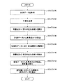
図2は、このようなタイヤ変形量算出装置10にて行われるタイヤ変形量算出方法を示すフローチャートである。図3(a)〜(d)及び図4(a)〜(c)は、タイヤ変形量算出方法の各処理で得られる結果の一例を示している。これらの結果は、いずれも加速度センサ2のうち、タイヤのラジアル方向(半径方向)の加速度の計測データから、ラジアル方向のタイヤのトレッド部の変形量を算出する場合の結果である。
本発明は、タイヤのラジアル方向の加速度の計測データを用いてタイヤのトレッド部のラジアル方向の変形量を算出する場合に限らず、タイヤの周方向又は幅方向の加速度の計測データから、周方向又は幅方向の変形量を算出することもできる。さらに、タイヤの周方向及び幅方向の加速度の計測データを同時に取得してこの2つのデータから、周方向及び幅方向の変形量を同時に算出することもできる。
FIG. 2 is a flowchart showing a tire deformation amount calculation method performed by such a tire deformation
The present invention is not limited to calculating the radial deformation amount of the tread portion of the tire using the measurement data of the radial acceleration of the tire, but from the measurement data of the acceleration in the circumferential direction or the width direction of the tire. Alternatively, the amount of deformation in the width direction can be calculated. Furthermore, it is also possible to simultaneously obtain the measurement data of the acceleration in the circumferential direction and the width direction of the tire, and simultaneously calculate the deformation amounts in the circumferential direction and the width direction from these two data.
まず、アンプ4で増幅された加速度がデータ取得部12に供給され、所定のサンプリング周波数にてサンプリングされて、デジタル化した計測データが取得される(ステップS100)。
次に、取得された計測データは、信号処理部14に供給され、まず、フィルタによる平滑化処理が行われる(ステップS102)。図3(a)に示すように、信号処理部14に供給された計測データはノイズ成分が多く含まれるため、平滑化処理により、図3(b)に示すように滑らかなデータとされる。フィルタは、例えば、所定の周波数をカットオフ周波数とするデジタルフィルタが用いられる。カットオフ周波数は、転動速度やノイズ成分によって変化するが、例えば転動速度が60(km/時)の場合、カットオフ周波数は、0.5〜2(kHz)とされる。この他に、デジタルフィルタの替わりに、移動平均処理やトレンドモデル等を用いて平滑化処理を行ってもよい。
図3(b)に示す時系列のグラフでは横軸に時間軸を採るとともに、同時にタイヤの周上位置をθ(度)で表している。タイヤの周上位置θ(度)は、図1に示すようなタイヤの接地面の中心位置(θ=180度)に対して対向する点O(図1参照)を基準とする角度である。このような周上位置θ(度)は、タイヤに記されたマークを図示されないマーク検知手段で検知することにより、マークの周上の位置と加速度センサ2の周上位置との相対位置関係から、転動中のタイヤの周上位置θ(度)を定めることができる。また、時系列のグラフにおいて、極小値の位置を基準として、この位置を接地面の中心位置(θ=180度)として転動中のタイヤの周上位置θ(度)を定めてもよい。
図3(b)において接地面の中心位置はθ=180度、540度及び900度に該当し、図3(b)ではタイヤの略3周分の加速度の計測データが示されている。
First, the acceleration amplified by the
Next, the acquired measurement data is supplied to the
In the time-series graph shown in FIG. 3B, the horizontal axis represents the time axis, and the circumferential position of the tire is represented by θ (degrees) at the same time. The circumferential position θ (degree) of the tire is an angle with respect to a point O (see FIG. 1) facing the center position (θ = 180 degrees) of the ground contact surface of the tire as shown in FIG. Such a circumferential position θ (degrees) is detected from a relative positional relationship between the circumferential position of the mark and the circumferential position of the
In FIG. 3B, the center position of the contact surface corresponds to θ = 180 degrees, 540 degrees, and 900 degrees, and FIG. 3B shows measurement data of acceleration for approximately three laps of the tire.
次に、平滑処理された加速度の計測データから背景成分1が算出される(ステップS104)。
ラジアル方向の加速度の背景成分1は、タイヤの転動中の遠心力(向心力)の加速度成分及び重力加速度成分を含む(なお、周方向の加速度の背景成分においても、これらの成分を含む)。図3(c)では背景成分1の波形が点線で示されている。この背景成分1は、接地面の中心位置θ=180度、540度及び900度のそれぞれを中心として、絶対値で0以上90度未満の角度の範囲を除いた周上の領域(第2の領域)で加速度の計測データに近似するように求められる。
Next, the
The
具体的に説明すると、タイヤの周上の領域を、路面接地領域を含む第1の領域とこれ以外の第2の領域とに分け、第1の領域として、θ=90度より大きく270度未満、450度より大きく720度未満、810度より大きく980度未満の領域を定め、第2の領域として、θ=0以上90度以下及び270度以上360度以下、360度以上450度以下及び630度以上720度以下、720度以上810度以下及び980度以上1070度以下の領域を定める。背景成分1は、上記第2の領域中の複数の周上位置(θ又はθに対応する時間)を節点として用いて、予め定められた関数群、例えば3次のスプライン関数を用いて、第1の領域及び第2の領域のデータに対して最小二乗法により第1の近似曲線を算出することによって求める。節点は、スプライン関数の局所的な曲率(屈曲性)を規定する横軸上の拘束条件を意味する。図3(b)の例では、図3(b)中の「△」で示される位置、すなわちθ=10,30,50,70,90,270,290,310,330,350,370,390,410,430,450,630,650,670,690,710,730,750,770,790,810,990,1010,1030,1050,1070度における時間を節点としている。
More specifically, the area on the circumference of the tire is divided into a first area including the road surface contact area and a second area other than this, and the first area is larger than θ = 90 degrees and less than 270 degrees. , More than 450 degrees and less than 720 degrees, more than 810 degrees and less than 980 degrees, and θ = 0 to 90 degrees and 270 degrees to 360 degrees, 360 degrees to 450 degrees and 630 as the second area An area of from 720 degrees to 720 degrees, from 720 degrees to 810 degrees, and from 980 degrees to 1070 degrees is defined. The
図3(b)に示すデータに対して、上記節点を有する3次のスプライン関数で関数近似を行うことにより、図3(c)において点線で示される近似曲線が算出される。関数近似する際、第1の領域には節点はなく、第2の領域の複数の節点のみを用いて関数近似を行い、かつ関数近似に際して行う最小二乗法では重み係数を用いる。この重み係数は、第2の領域の重み係数を1とすると、第1の領域の重み係数は0.01に設定されて処理が行われる。このように背景成分1を算出する際、第1の重み係数を第2の重み係数に対して小さくし、かつ第1の領域に節点を定めないのは、第1の近似曲線を、主に第2の領域における加速度の計測データから算出するためである。第2の領域では、トレッド部の接地による変形が小さくかつその変形は周上で滑らかに変化するため、タイヤの転動中の加速度は遠心力(向心力)の加速度成分及び重力加速度成分が支配的である。これに対し、第1の領域では、タイヤのトレッド部は接地変形に基づいて大きくかつ急激に変化する。このため接地変形に基づく加速度成分の変化が、タイヤの回転に基づく遠心力(向心力)の加速度成分及び重力加速度成分の変化に比べて大きくなる。すなわち、第2の領域の加速度の計測データは、概略、タイヤの転動中の遠心力(向心力)の加速度成分及び重力加速度成分であり、第2の領域の加速度の計測データを主に用いて第1の近似曲線を算出することで、第2の領域のみならず、第1の領域におけるタイヤの転動中の遠心力(向心力)の加速度成分及び重力加速度成分を精度よく推定することができる。
なお、図3(c)では、接地中心位置(θ=180,540,900度)を中心として絶対値で0以上90度未満の角度の範囲を第1の領域としたが、本発明における第1の領域は、接地中心位置から少なくとも絶対値で0以上60度未満の角度の範囲であればよい。
By performing function approximation on the data shown in FIG. 3B with a cubic spline function having the nodes, an approximate curve indicated by a dotted line in FIG. 3C is calculated. When performing function approximation, there are no nodes in the first region, function approximation is performed using only a plurality of nodes in the second region, and a weighting factor is used in the least square method performed in function approximation. As for this weighting factor, when the weighting factor of the second region is 1, the weighting factor of the first region is set to 0.01 and processing is performed. When the
In FIG. 3 (c), the first range is an angle range from 0 to less than 90 degrees in absolute value with the ground contact center position (θ = 180, 540, 900 degrees) as the center. The
次に、算出された背景成分1を表す第1の近似曲線を、ステップS102で処理された加速度の計測データから差し引くことで、計測データからタイヤの回転に基づく加速度成分及び重力加速度成分が除去される(ステップS106)。図3(d)には、除去後の加速度の時系列データが示されている。これにより、タイヤのトレッド部の接地変形に基づく加速度の成分を抽出することができる。
Next, the acceleration component based on the rotation of the tire and the gravitational acceleration component are removed from the measurement data by subtracting the first approximate curve representing the calculated
次に、算出された、接地変形に基づく加速度の時系列データは、変形量算出部16において2階の時間積分が施され、変位データが生成される(ステップS108)。
なお、積分の対象となる加速度のデータには通常ノイズ成分を含むので、2階積分を行うとノイズ成分も同時に積分され、精度の高い変位データを求めることはできない。図4(a)は、図3(c)の加速度の時系列データを時間に関して2階積分した結果である。図4(a)に示されるように、時間と共に変位が増大していることが見られる。これは、積分の対象となる加速度の時系列データにノイズ成分を含み、積分により積算されていくからである。一般に、定常状態で転動するタイヤのトレッド部の注目する一点の変形量又は変位を観察した場合、タイヤの回転周期を単位として周期的な変化を示す。したがって、時間と共に変位が増大することは通常ありえない。
そこで、2階の時間積分が施されて得られた変位データが、タイヤの回転周期を単位として周期的な変化を示すように、この変位データに対して以下の処理が行われる。
Next, the calculated time series data of acceleration based on ground deformation is subjected to second-order time integration in the deformation
Since acceleration data to be integrated usually includes a noise component, if second-order integration is performed, the noise component is also integrated at the same time, and high-precision displacement data cannot be obtained. FIG. 4A shows the result of second-order integration of the time series data of the acceleration shown in FIG. 3C with respect to time. As shown in FIG. 4A, it can be seen that the displacement increases with time. This is because the time series data of acceleration to be integrated includes a noise component and is integrated by integration. In general, when the amount of deformation or displacement of a point of interest in a tread portion of a tire that rolls in a steady state is observed, a periodic change is shown with the rotation period of the tire as a unit. Therefore, it is usually not possible for the displacement to increase with time.
Therefore, the following processing is performed on the displacement data so that the displacement data obtained by performing the second-order time integration shows a periodic change in units of the tire rotation cycle.
すなわち、ステップS104において、背景成分1を算出した方法と同様に、変位データに含まれるノイズ成分を背景成分2として算出する(ステップS110)。
具体的に説明すると、タイヤの周上の領域を、路面との接地領域を含む第3の領域とこれ以外の第4の領域とに分け、第3の領域として、θ=90度より大きく270度未満、450度より大きく720度未満、810度より大きく980度未満の領域を定め、第4の領域として、θ=0以上90度以下及び270度以上360度以下、360度以上450度以下及び630度以上720度以下、720度以上810度以下及び980度以上1070度以下の領域を定める。背景成分2は、上記第4の領域中の複数の周上位置(θ又はθに対応する時間)を節点として用いて、予め定められた関数群を用いて、第3の領域及び第4の領域のデータに対して最小二乗法により第2の近似曲線を算出することによって求める。なお、第3の領域は、上述した第1の領域と一致する領域であってもよいし、異なる領域であってもよい。また、第4の領域は、上述した第2の領域と一致する領域であってもよいし、異なる領域であってもよい。節点は、上述したように、スプライン関数の局所的な曲率(屈曲性)を規定する横軸上の拘束条件を意味する。図4(b)には、背景成分2を表す第2の近似曲線が点線で示されている。図4(b)の例では、図4(b)中の「△」で示される位置、すなわちθ=10,30,50,70,90,270,290,310,330,350,370,390,410,430,450,630,650,670,690,710,730,750,770,790,810,990,1010,1030,1050,1070度における時間を節点としている。
That is, in the step S104, the noise component included in the displacement data is calculated as the
More specifically, the region on the circumference of the tire is divided into a third region including a contact region with the road surface and a fourth region other than this, and the third region is larger than θ = 90
図4(a)に示す変位データに対して、上記節点のデータ点を通る3次のスプライン関数で関数近似を行うことにより、図4(b)において点線で示される第2の近似曲線が算出される。関数近似する際、第3の領域には節点はなく、第4の領域の複数の節点のみを用いて関数近似を行い、かつ関数近似に際して行う最小二乗法で用いる第4の領域の重み係数を1とし、第3の領域の重み係数を0.01として処理が行われる。このように背景成分2を算出する際、第1の重み係数を小さくし、かつ第3の領域に節点を定めないのは、第4の領域における変位データを主に用いて背景成分2を算出するためである。第4の領域では、トレッド部の接地による変形は小さくかつその変形は周上で滑らかに変化するため、タイヤの変形量は周上で小さく、その変化も極めて小さい。これに対して、第3の領域では、タイヤのトレッド部は接地変形に基づいて大きく変位しかつ急激に変化する。このため接地変形に基づく変形量は周上で大きくかつ急激に変化する。すなわち、第4の領域におけるトレッド部の変形量は第3の変形量と対比して概略一定を示す。これより、第4の領域の2階積分により得られた変位データを主に用いて第2の近似曲線を算出することで、第4の領域のみならず、路面との接地領域を含む第3の領域におけるタイヤの転動中の変形量を精度よく求めることができる。
図4(b)には、第4の領域の変位データを主に用いて算出された第2の近似曲線が点線で示されている。第4の領域では、第2の近似曲線は変位データ(実線)と略一致している。
By performing function approximation on the displacement data shown in FIG. 4A with a cubic spline function passing through the data points of the nodes, a second approximate curve indicated by a dotted line in FIG. 4B is calculated. Is done. When performing function approximation, there is no node in the third region, function approximation is performed using only a plurality of nodes in the fourth region, and the weighting factor of the fourth region used in the least square method performed in function approximation is used. The processing is performed with 1 being set to 1, and the weighting factor of the third region being set to 0.01. When the
In FIG. 4B, the second approximate curve calculated mainly using the displacement data of the fourth region is indicated by a dotted line. In the fourth region, the second approximate curve substantially coincides with the displacement data (solid line).
最後に、背景成分2として算出された近似曲線を、ステップS110で算出された変位データから差し引き、トレッド部の接地変形に基づく変形量の周上の分布が算出される(ステップS112)。
図4(c)は、図3(b)に示す変位信号(実線)から第2の近似曲算線(点線)を差し引くことにより算出される、トレッド部の接地変形に基づく変形量の分布を示している。図4(c)は、トレッド部上の所定の測定位置が周上を回転して変位するときの3回転分の変形量の分布(3回の接地)を示している。接地のたびに変形量が変化していることが見られる。
Finally, the approximate curve calculated as the
FIG. 4C shows the distribution of deformation based on the ground deformation of the tread portion, which is calculated by subtracting the second approximate curve (dotted line) from the displacement signal (solid line) shown in FIG. 3B. Show. FIG. 4C shows a distribution of deformation amounts for three rotations (three times of ground contact) when a predetermined measurement position on the tread portion rotates around the circumference and is displaced. It can be seen that the amount of deformation changes with each contact.
このようにして算出される変形量は、データ出力部18において、出力用データとしてまとめられて、ディスプレイ24や図示されないプリンタに出力される。このような方法により算出される変形量は、タイヤの有限要素モデルを用いてシミュレーションを行ったときの変形量と精度良く一致する。
最後に、図4(c)に示すトレッド部における変形量の時系列データについて時間に関して2階微分を行うことにより、図3(d)に示す加速度からノイズ成分が除去された、トレッド部の変形量に対応した加速度の時系列データ、すなわち、トレッド部の接地変形に基づく、ノイズ成分を含まない加速度の時系列データ(後述する図5(a)参照)が算出される(ステップS114)。
さらに、データ出力部18では、変形量を用いて転動中のタイヤの接地領域及び接地長を求めることができる。
The deformation amount calculated in this way is collected as output data in the data output unit 18 and output to the display 24 or a printer (not shown). The deformation amount calculated by such a method coincides with the deformation amount when the simulation is performed using the tire finite element model with high accuracy.
Finally, deformation of the tread portion in which noise components are removed from the acceleration shown in FIG. 3D by performing second-order differentiation with respect to time for the time series data of the deformation amount in the tread portion shown in FIG. Acceleration time-series data corresponding to the amount, that is, acceleration time-series data (see FIG. 5A described later) that does not include a noise component based on the ground deformation of the tread portion is calculated (step S114).
Further, the data output unit 18 can determine the contact area and the contact length of the rolling tire using the deformation amount.
図5(a)は、接地領域及び接地長を求める方法を示している。
まず、ステップS114によって抽出されたタイヤのトレッド部の接地変形に基づく、ノイズ成分を含まない加速度の時系列データにおいて、加速度が急激に変化して0を横切る点が2つ求められる。次に、求められた2つの点に対応する変位データ中の位置が求められ、この位置を図5(a)に示すように接地前端及び接地後端の位置とする。このように加速度の時系列データが急激に大きく変化する部分を、接地前端及び接地後端と定めることができるのは、トレッド部が回転して接地領域に来るとき、または接地領域から出るとき、タイヤが急激に変形するからである。また、加速度の時系列データが0を横切る位置を明確に定めることができる。
なお、図5(a)中の下のグラフは、タイヤのラジアル方向及び周方向で表される極座標系から、タイヤの上下方向、前後方向で表される直交座標系に変えて書き表したグラフであり、接地により変形したタイヤの変形形状を示すグラフである。このグラフ上において、接地前端と接地後端の位置を定めることにより接地長を評価することができる。
このような方法により算出される接地長は、タイヤの有限要素モデルを用いてシミュレーションを行ったときの接地長と精度良く一致する。
FIG. 5A shows a method for obtaining the grounding area and the grounding length.
First, in the time series data of acceleration not including a noise component based on the ground deformation of the tire tread portion extracted in step S114, two points where the acceleration changes rapidly and crosses 0 are obtained. Next, the positions in the displacement data corresponding to the two obtained points are obtained, and these positions are set as the positions of the front end and the rear end as shown in FIG. The portion where the time series data of acceleration changes greatly in this way can be defined as the ground contact front end and the ground back end when the tread portion rotates and comes into the ground region, or when it comes out of the ground region. This is because the tire deforms rapidly. Further, it is possible to clearly determine the position where the time series data of acceleration crosses zero.
In addition, the lower graph in FIG. 5A is a graph written by changing from a polar coordinate system expressed in the radial direction and the circumferential direction of the tire to an orthogonal coordinate system expressed in the vertical direction and the front-rear direction of the tire. It is a graph which shows the deformation | transformation shape of the tire which has existed and deform | transformed by the grounding. On this graph, the contact length can be evaluated by determining the positions of the front end and the rear end.
The contact length calculated by such a method coincides with the contact length accurately when a simulation is performed using a finite element model of a tire.
また、図5(a)に示す方法に変えて、図5(b)に示す方法により接地領域及び接地長を求めることもできる。
具体的には、図5(b)は、タイヤの接地中心位置を原点としたときの、タイヤの前後方向の位置をタイヤのトレッド部の外径Rで除算して規格化するとともに、タイヤの上下方向の位置を外径Rで除算して規格化して、タイヤの変形形状を表したグラフである。図5(b)に示されるようにタイヤの変形形状における、上下方向の最下点から上方向に一定距離δ離れた直線を横切る位置を接地前端に対応する規格化位置及び接地後端に対応する規格化位置とする。この規格化位置をそれぞれ求め外径Rを乗算することにより接地前端及び接地後端の位置を求めることができ、これによりタイヤの接地領域及び接地長を求めることができる。前端位置及び後端位置を定めるために用いる一定距離δは、例えば0.001〜0.005の範囲にあることが好ましい。また、最下点から上方向にトレッド部が離れたときの距離の自乗値が所定の値を横切る位置を接地前端及び接地後端とすることもできる。例えば、上記所定の値は、0.00002(cm2)〜0.00005(cm2)の範囲の値であり、好適には0.00004(cm2)が用いられる。静止したタイヤに負荷する荷重を変えて接地長を種々調べた測定結果と、上記方法により求めた接地長の結果は極めて高い相関性を示すことが確認されている。
図6は、上記方法により求められた接地領域及び接地長の例を示している。図6中の太線の部分が接地領域を示している。
Further, in place of the method shown in FIG. 5A, the ground region and the ground length can be obtained by the method shown in FIG.
Specifically, FIG. 5 (b) shows the normalization by dividing the position in the front-rear direction of the tire by the outer diameter R of the tread portion of the tire when the ground contact center position of the tire is the origin. It is the graph which expressed the deformation | transformation shape of the tire by dividing the position of an up-down direction by the outer diameter R, and normalizing. As shown in FIG. 5 (b), in the deformed shape of the tire, the position crossing the straight line that is a fixed distance δ upward from the lowest point in the vertical direction corresponds to the standardized position corresponding to the front end of contact and the rear end of the contact Standardized position. By obtaining the normalized positions and multiplying them by the outer diameter R, the positions of the front contact end and the rear contact end can be determined, whereby the contact area and the contact length of the tire can be determined. The fixed distance δ used for determining the front end position and the rear end position is preferably in the range of 0.001 to 0.005, for example. In addition, the position where the square value of the distance when the tread portion is separated upward from the lowest point crosses a predetermined value can be set as the ground contact front end and the ground contact rear end. For example, the predetermined value is in the range of 0.00002 (cm 2 ) to 0.00005 (cm 2 ), and preferably 0.00004 (cm 2 ). It has been confirmed that the measurement results obtained by variously examining the contact length by changing the load applied to the stationary tire and the result of the contact length obtained by the above method show extremely high correlation.
FIG. 6 shows an example of the contact area and contact length obtained by the above method. A thick line portion in FIG. 6 indicates a grounding region.
上記例はいずれもタイヤのトレッド部のラジアル方向の加速度の計測データを用いてタイヤのラジアル方向の変形量を算出するものであるが、本発明においては、タイヤのトレッド部の周方向あるいは幅方向(タイヤの回転軸に平行な方向)の加速度の計測データを取得して、タイヤの周方向あるいは幅方向の変形量を、図2に示す方法により算出することもできる。すなわち、本発明のタイヤ変形量算出方法では、タイヤの周方向に対して直交するラジアル方向の加速度の計測データ、タイヤの周方向の加速度の計測データ及びタイヤの幅方向の加速度の計測データの少なくとも1つの計測データを用いて、タイヤの変形量を算出することができる。 In any of the above examples, the amount of deformation in the radial direction of the tire is calculated using the measurement data of the radial acceleration of the tread portion of the tire. In the present invention, the circumferential direction or the width direction of the tire tread portion is calculated. It is also possible to obtain acceleration measurement data (in a direction parallel to the rotation axis of the tire) and calculate the amount of deformation in the circumferential direction or width direction of the tire by the method shown in FIG. That is, in the tire deformation amount calculation method according to the present invention, at least the radial acceleration measurement data orthogonal to the tire circumferential direction, the tire circumferential acceleration measurement data, and the tire width acceleration measurement data are at least selected. The tire deformation amount can be calculated using one measurement data.
図7(a),(b)は、本発明のタイヤ変形量算出方法を用いて取得されたトレッド部の内周面の変形の軌跡を示した一例のグラフであり、ラジアル方向の加速度と周方向の加速度を用いて算出されたタイヤの変形量を示している。加速度は、トレッド部の内周面のセンター部分に加速度センサを貼り付けて計測したデータである。
図7(a)の例は、タイヤサイズ205/70R15 95H、転動速度60(km/時)、空気圧200(kPa)、荷重4(kN)の条件である。図7(b)の例は、タイヤサイズ205/70R15 95H、転動速度40(km/時)、空気圧200(kPa)スリップ角度0の条件である。図7(a),(b)より、スリップ角度が変化することにより、又荷重が変化することにより変形形状が変化することが見られる。
一方、図8(a),(b)は、本発明のタイヤ変形量算出方法を用いて取得されたトレッド部の内周面の変形の軌跡を示した一例のグラフであり、周方向及び幅方向の加速度を用いて算出されたタイヤの周方向変形量及び幅方向変形量を示している。
図8(a)の例は、タイヤサイズ205/70R15 95H、転動速度60(km/時)、空気圧200(kPa)、荷重4(kN)の条件である。図8(b)の例は、タイヤサイズ205/70R15 95H、転動速度40(km/時)、空気圧200(kPa)スリップ角度0の条件である。図8(a)では、スリップ角度の付与により、セリアル側にタイヤが変形することが見られる。また、図8(b)では、荷重の増大に伴って、周方向及び幅方向の変形量が大きくなり、タイヤのトレッド部が幅方向のうちセリアル側に変形していることがわかる。
FIGS. 7A and 7B are graphs showing an example of the deformation trajectory of the inner peripheral surface of the tread portion obtained by using the tire deformation amount calculation method of the present invention. The deformation amount of the tire calculated using the acceleration in the direction is shown. The acceleration is data measured by attaching an acceleration sensor to the center portion of the inner peripheral surface of the tread portion.
The example of Fig.7 (a) is the conditions of tire size 205 / 70R15 95H, rolling speed 60 (km / h), air pressure 200 (kPa), and load 4 (kN). The example of FIG.7 (b) is the conditions of tire size 205 / 70R15 95H, rolling speed 40 (km / h), and air pressure 200 (kPa)
8A and 8B are graphs showing an example of the deformation trajectory of the inner peripheral surface of the tread portion obtained by using the tire deformation amount calculation method according to the present invention. The amount of deformation in the circumferential direction and the amount of deformation in the width direction of the tire calculated using the acceleration in the direction are shown.
The example of FIG. 8A is a condition of tire size 205 / 70R15 95H, rolling speed 60 (km / hour), air pressure 200 (kPa), and load 4 (kN). The example of FIG.8 (b) is the conditions of tire size 205 / 70R15 95H, rolling speed 40 (km / h), and air pressure 200 (kPa)
このように、タイヤのトレッド部の変形量を、ラジアル方向、周方向及び幅方向のいずれの方向においても算出することができ、転動中のタイヤの変形形状や軌跡を得ることができる。なお、本願発明では、トレッド部の内周面に複数の加速度センサを周上に設けることで、トレッド部の周上の測定点を同時に取得することもできる。さらに、タイヤの幅方向に複数の加速度センサを設け、幅方向の接地長や接地領域の分布を求めることで、転動中のタイヤの接地形状を取得することもできる。
また、本発明で取得する加速度の計測データは、トレッド部の内周面に取り付けた加速度センサによる計測データのほか、タイヤ内部に埋め込んだ加速度センサによる計測データを用いることもできる。
As described above, the deformation amount of the tread portion of the tire can be calculated in any of the radial direction, the circumferential direction, and the width direction, and the deformed shape and trajectory of the rolling tire can be obtained. In addition, in this invention, the measurement point on the circumference of a tread part can also be acquired simultaneously by providing several acceleration sensors on the circumference on the inner peripheral surface of a tread part. Furthermore, by providing a plurality of acceleration sensors in the width direction of the tire and obtaining the contact length in the width direction and the distribution of the contact area, the contact shape of the rolling tire can be acquired.
The acceleration measurement data acquired in the present invention may be measurement data obtained by an acceleration sensor embedded in the tire as well as measurement data obtained by an acceleration sensor attached to the inner peripheral surface of the tread portion.
以上、本発明のタイヤ変形量算出方法及びタイヤ変形量算出装置について詳細に説明したが、本発明は上記実施形態に限定されず、本発明の主旨を逸脱しない範囲において、種々の改良や変更をしてもよいのはもちろんである。 As described above, the tire deformation amount calculation method and the tire deformation amount calculation device of the present invention have been described in detail. However, the present invention is not limited to the above-described embodiment, and various improvements and modifications can be made without departing from the gist of the present invention. Of course.
1 タイヤ
2 加速度センサ
3 受信機
4 アンプ
10 タイヤ変形量算出装置
12 データ取得部
14 信号処理部
16 変形量算出部
18 データ出力部
20 メモリ
22 CPU
24 ディスプレイ
DESCRIPTION OF
24 display
Claims (16)
転動中のタイヤの所定の部位に加速度センサを配置して得られる、少なくともタイヤ1回転分の加速度の計測データを取得する取得ステップと、
取得した加速度の計測データから背景成分を除去することで、タイヤの変形に基づく加速度の時系列データを抽出する信号処理ステップと、
前記タイヤの変形に基づく加速度の時系列データに対して2階の時間積分を行って変位データを求めることにより、タイヤの前記所定の部位における変形量を算出する変形量算出ステップと、を有することを特徴とするタイヤ変形量算出方法。 A tire deformation amount calculation method for calculating a deformation amount of a tire when the tire rolls on a road surface,
An acquisition step of acquiring measurement data of acceleration for at least one rotation of the tire , which is obtained by arranging an acceleration sensor at a predetermined part of the rolling tire;
A signal processing step of extracting time series data of acceleration based on tire deformation by removing a background component from the acquired acceleration measurement data;
A deformation amount calculating step of calculating a deformation amount at the predetermined portion of the tire by obtaining displacement data by performing second-order time integration on the time series data of acceleration based on the deformation of the tire. A method for calculating a tire deformation amount.
前記信号処理ステップでは、前記第2の領域の加速度の計測データを近似することにより、前記第1の領域上及び前記第2の領域上で定められる第1の近似曲線を算出し、前記取得ステップで取得した加速度の波形からこの第1の近似曲線を差し引くことにより、前記第1の領域及び前記第2の領域におけるタイヤの変形量に基づく加速度の時系列データを抽出することを特徴とする請求項2に記載のタイヤ変形量算出方法。 The area on the circumference of the tread portion of the tire is divided into a first area including a ground contact area in contact with a road surface and a second area other than this.
In the signal processing step, a first approximate curve defined on the first region and the second region is calculated by approximating acceleration measurement data of the second region, and the obtaining step by subtracting the first approximation curve from the obtained acceleration waveform in, claims and extracts time series data of acceleration due to the deformation amount of the tire in the first region and the second region Item 3. A tire deformation amount calculation method according to Item 2.
前記変形量算出ステップでは、前記第4の領域の前記変位データを近似することにより、前記第1の領域上及び前記第2の領域上で定められる第2の近似曲線を算出し、前記変位データの波形からこの第2の近似曲線を差し引くことにより、タイヤの変形量を算出する請求項3〜6のいずれか1項に記載のタイヤ変形量算出方法。 In the deformation amount calculating step, by approximating the displacement data of the fourth area, a second approximate curve defined on the first area and the second area is calculated, and the displacement data The tire deformation amount calculation method according to any one of claims 3 to 6, wherein the tire deformation amount is calculated by subtracting the second approximate curve from the waveform.
転動中のタイヤの所定の部位に加速度センサを配置して得られる、少なくともタイヤ1回転分の加速度の計測データを取得するデータ取得部と、
取得した加速度の計測データから背景成分を除去することで、タイヤの変形に基づく加速度の時系列データを抽出する信号処理部と、
前記タイヤの変形に基づく加速度の時系列データに対して2階の時間積分を行って変位データを求めることにより、タイヤの所定の部位における変形量を算出する変形量算出部と、を有することを特徴とするタイヤ変形量算出装置。 A tire deformation amount calculating device for calculating a deformation amount of a tire when the tire rolls on a road surface,
A data acquisition unit that acquires measurement data of acceleration for at least one rotation of the tire , which is obtained by arranging an acceleration sensor at a predetermined part of the rolling tire;
A signal processing unit that extracts time series data of acceleration based on tire deformation by removing background components from the acquired acceleration measurement data;
A deformation amount calculation unit that calculates a deformation amount at a predetermined portion of the tire by performing second-order time integration on the time series data of acceleration based on the deformation of the tire to obtain displacement data; A tire deformation amount calculating device.
Priority Applications (4)
| Application Number | Priority Date | Filing Date | Title |
|---|---|---|---|
| JP2004335417A JP3895347B2 (en) | 2004-11-19 | 2004-11-19 | Tire deformation amount calculation method and tire deformation amount calculation device |
| EP05809210.7A EP1813930B1 (en) | 2004-11-19 | 2005-11-21 | Tire deformation calculating method and tire deformation calculating apparatus |
| US10/594,207 US7370523B2 (en) | 2004-11-19 | 2005-11-21 | Tire deformation calculating method and tire deformation calculating apparatus |
| PCT/JP2005/021369 WO2006054745A1 (en) | 2004-11-19 | 2005-11-21 | Tire deformation amount calculating method and tire deformation amount calculating device |
Applications Claiming Priority (1)
| Application Number | Priority Date | Filing Date | Title |
|---|---|---|---|
| JP2004335417A JP3895347B2 (en) | 2004-11-19 | 2004-11-19 | Tire deformation amount calculation method and tire deformation amount calculation device |
Publications (3)
| Publication Number | Publication Date |
|---|---|
| JP2006145366A JP2006145366A (en) | 2006-06-08 |
| JP2006145366A5 JP2006145366A5 (en) | 2006-08-24 |
| JP3895347B2 true JP3895347B2 (en) | 2007-03-22 |
Family
ID=36407278
Family Applications (1)
| Application Number | Title | Priority Date | Filing Date |
|---|---|---|---|
| JP2004335417A Expired - Fee Related JP3895347B2 (en) | 2004-11-19 | 2004-11-19 | Tire deformation amount calculation method and tire deformation amount calculation device |
Country Status (4)
| Country | Link |
|---|---|
| US (1) | US7370523B2 (en) |
| EP (1) | EP1813930B1 (en) |
| JP (1) | JP3895347B2 (en) |
| WO (1) | WO2006054745A1 (en) |
Families Citing this family (27)
| Publication number | Priority date | Publication date | Assignee | Title |
|---|---|---|---|---|
| US7429801B2 (en) * | 2002-05-10 | 2008-09-30 | Michelin Richerche Et Technique S.A. | System and method for generating electric power from a rotating tire's mechanical energy |
| US7497114B2 (en) * | 2004-04-29 | 2009-03-03 | Nxp B.V. | Tag used for monitoring the tire pressure |
| JP4604677B2 (en) * | 2004-11-19 | 2011-01-05 | 横浜ゴム株式会社 | Tire slip condition detection method and tire slip condition detection apparatus |
| JP4021919B2 (en) * | 2006-04-21 | 2007-12-12 | 横浜ゴム株式会社 | Deflection calculation method for tire rolling, data accumulation method for tire rolling, and contact length calculation method for tire rolling |
| JP4229965B2 (en) * | 2006-11-14 | 2009-02-25 | 横浜ゴム株式会社 | Brake control method and brake control device |
| US8051705B2 (en) | 2006-11-14 | 2011-11-08 | Kabushiki Kaisha Bridgestone | Tire equipped with a sensor and a method of measuring strain amount of the tire |
| US8371159B2 (en) | 2007-07-11 | 2013-02-12 | Kabushiki Kaisha Bridgestone | Method for estimating the wear of a tire |
| JP5072463B2 (en) * | 2007-07-11 | 2012-11-14 | 株式会社ブリヂストン | Tire wear detection method and tire wear detection device |
| JP5183114B2 (en) * | 2007-07-11 | 2013-04-17 | 株式会社ブリヂストン | Tire wear estimation method and tire wear estimation apparatus |
| US7472587B1 (en) * | 2007-09-18 | 2009-01-06 | Infineon Technologies Ag | Tire deformation detection |
| DE102008007775A1 (en) * | 2008-02-06 | 2009-08-13 | Robert Bosch Gmbh | Method and device for determining the change in the footprint of a tire |
| JP5309763B2 (en) * | 2008-07-29 | 2013-10-09 | 横浜ゴム株式会社 | Tire contact length calculation method and apparatus |
| JP2011057042A (en) * | 2009-09-08 | 2011-03-24 | Bridgestone Corp | Method and device for estimating grounding shape of tire |
| DE102009057580B4 (en) | 2009-12-09 | 2023-06-15 | Continental Automotive Technologies GmbH | Contact patch evaluation circuit for an electromechanical converter of a tire |
| JP5498238B2 (en) * | 2010-04-22 | 2014-05-21 | 株式会社ブリヂストン | Simulation method and simulation apparatus |
| US9429497B2 (en) * | 2011-12-29 | 2016-08-30 | Michelin Recherche Et Technique S.A. | System and method for determining tire uniformity parameters from piezoelectric measurements in the tire counter-deflection zone |
| GB2510434A (en) * | 2013-02-05 | 2014-08-06 | Schrader Electronics Ltd | Pulse width measuring method for use in e.g. a tyre monitor |
| JP2017116991A (en) * | 2015-12-21 | 2017-06-29 | 京セラ株式会社 | Portable terminal and vehicle |
| JP7009098B2 (en) * | 2017-07-19 | 2022-01-25 | 株式会社ブリヂストン | Road surface condition estimation method |
| GB2565051A (en) * | 2017-07-27 | 2019-02-06 | Continental Automotive Gmbh | Method and device for monitoring a behavior of a tire of a vehicle |
| US10549587B2 (en) | 2017-10-19 | 2020-02-04 | Infineon Technologies Ag | Method, component, tire-mounted TPMS module, TPMS system, and machine readable storage or computer program for determining time information of at least one contact patch event of a rolling tire, method for locating a tire |
| US20190118592A1 (en) * | 2017-10-19 | 2019-04-25 | Infineon Technologies Ag | Method, Tire-Mounted TPMS Component, and Machine Readable Storage or Computer Program for Determining a Duration of at Least one Contact Patch Event of a Rolling Tire |
| CN110966978B (en) * | 2018-09-28 | 2021-10-26 | 千寻位置网络有限公司 | Bicycle tire deformation detection method and device and bicycle |
| CA3120652A1 (en) * | 2018-12-21 | 2020-06-25 | Compagnie Generale Des Etablissements Michelin | Method for obtaining the deformation of a tyre under load when running |
| CN113195262B (en) * | 2018-12-21 | 2023-05-05 | 米其林集团总公司 | Method for obtaining deformation of a tyre under load during driving |
| KR102352446B1 (en) * | 2020-02-17 | 2022-01-19 | 한국타이어앤테크놀로지 주식회사 | Tire abnormality detection device and its detection mehtod |
| CN114001703B (en) * | 2021-10-09 | 2023-07-28 | 四川轻化工大学 | Landslide deformation data real-time filtering method |
Family Cites Families (25)
| Publication number | Priority date | Publication date | Assignee | Title |
|---|---|---|---|---|
| JP2539560B2 (en) | 1991-09-20 | 1996-10-02 | 株式会社日立製作所 | Semiconductor acceleration sensor and airbag system |
| JP3182885B2 (en) | 1992-06-17 | 2001-07-03 | 株式会社デンソー | Method for manufacturing semiconductor device |
| DE69334194T2 (en) | 1992-04-22 | 2008-12-04 | Denso Corp., Kariya-shi | Method for producing a semiconductor device |
| JP3214169B2 (en) * | 1993-07-23 | 2001-10-02 | 日産自動車株式会社 | Differential limit torque control device |
| JPH08297033A (en) | 1995-04-27 | 1996-11-12 | Omron Corp | Navigation system |
| US5825286A (en) * | 1995-05-08 | 1998-10-20 | Semisystems, Inc. | Vehicular data collection and transmission system and method |
| JP3509331B2 (en) * | 1995-10-11 | 2004-03-22 | 本田技研工業株式会社 | Vehicle wheel pressure reduction judgment device |
| JPH1063288A (en) | 1996-08-23 | 1998-03-06 | Aqueous Res:Kk | Voice recognition device |
| US5717376A (en) * | 1996-09-03 | 1998-02-10 | United Technologies Automotive, Inc. | System for determining failure of remote sensing device |
| US5900808A (en) * | 1997-02-21 | 1999-05-04 | Lebo; Michael E. | Low pressure warning system |
| FR2764241B1 (en) | 1997-06-10 | 1999-08-20 | Dassault Electronique | MONITORING A TIRE BY ACCELERATION MEASURE |
| JP3499470B2 (en) | 1998-12-25 | 2004-02-23 | トヨタ自動車株式会社 | Wheel state related information supply device and tire abnormality state notification device |
| JP2000292330A (en) | 1999-04-07 | 2000-10-20 | Shiyuto Kosoku Doro Gijutsu Center | Mobile road surface bend measuring device and mobile road surface bend measuring method |
| ES2238321T3 (en) * | 1999-11-18 | 2005-09-01 | Pirelli Pneumatici Societa Per Azioni | PROCEDURE AND DEVICE FOR SURVEILLANCE OF INSTANT BEHAVIOR OF A TIRE DURING THE OPERATION OF A MOTOR VEHICLE. |
| JP4121695B2 (en) | 2000-09-21 | 2008-07-23 | 横浜ゴム株式会社 | Tire exterior noise prediction method and recording medium recording tire exterior noise prediction program |
| JP2002317679A (en) * | 2001-02-19 | 2002-10-31 | Toyota Motor Corp | Vehicle control system to work well with differing tire conditional amount |
| US20030058118A1 (en) * | 2001-05-15 | 2003-03-27 | Wilson Kitchener C. | Vehicle and vehicle tire monitoring system, apparatus and method |
| JP2002340863A (en) | 2001-05-15 | 2002-11-27 | Toyota Central Res & Dev Lab Inc | Road surface determination device and system |
| ES2190877B2 (en) | 2001-06-26 | 2004-05-16 | Universidade De Santiago De Compostela | GEDAP METHOD (GENOTYPING BASED ON DIAGNOSTIC AMPLIFICATION PRODUCTS) TO DETECT AND / OR PREVENT GENOTIPED ERRORS FROM THE AMPLIFICATION PRODUCTS OF A POLYMORPHIC LOCUS. |
| JP3892722B2 (en) | 2001-12-21 | 2007-03-14 | 株式会社ブリヂストン | Road surface state and tire running state estimation device and vehicle control device |
| ES2534480T3 (en) | 2001-12-21 | 2015-04-23 | Kabushiki Kaisha Bridgestone | Method and apparatus for estimating the state of the surface of a road and the running state of a tire |
| FR2835919A1 (en) | 2002-02-08 | 2003-08-15 | Michelin Soc Tech | MEASUREMENT OF MAXIMUM ADHESION COEFFICIENT FROM KNOWLEDGE OF GENERATED EFFORTS AND SELF-ALIGNMENT TORQUE IN THE TIRE CONTACT AIR |
| CN1307064C (en) * | 2002-03-28 | 2007-03-28 | 倍耐力轮胎公司 | Method and system for monitoring state of tyre during running of motor vehicle |
| JP2004163140A (en) | 2002-11-11 | 2004-06-10 | Honda Motor Co Ltd | Apparatus for detecting amount of deformation of tire |
| JP2004340616A (en) | 2003-05-13 | 2004-12-02 | Yokohama Rubber Co Ltd:The | Semiconductor acceleration sensor |
-
2004
- 2004-11-19 JP JP2004335417A patent/JP3895347B2/en not_active Expired - Fee Related
-
2005
- 2005-11-21 WO PCT/JP2005/021369 patent/WO2006054745A1/en active Application Filing
- 2005-11-21 US US10/594,207 patent/US7370523B2/en not_active Expired - Fee Related
- 2005-11-21 EP EP05809210.7A patent/EP1813930B1/en active Active
Also Published As
| Publication number | Publication date |
|---|---|
| EP1813930B1 (en) | 2013-09-25 |
| WO2006054745A1 (en) | 2006-05-26 |
| US20070213953A1 (en) | 2007-09-13 |
| EP1813930A1 (en) | 2007-08-01 |
| JP2006145366A (en) | 2006-06-08 |
| US7370523B2 (en) | 2008-05-13 |
| EP1813930A4 (en) | 2010-01-20 |
Similar Documents
| Publication | Publication Date | Title |
|---|---|---|
| JP3895347B2 (en) | Tire deformation amount calculation method and tire deformation amount calculation device | |
| JP4604677B2 (en) | Tire slip condition detection method and tire slip condition detection apparatus | |
| JP4108740B2 (en) | Method and apparatus for calculating the size of a cornering force generated on a wheel | |
| JP4021919B2 (en) | Deflection calculation method for tire rolling, data accumulation method for tire rolling, and contact length calculation method for tire rolling | |
| EP1767422B1 (en) | Method and apparatus for evaluating a cornering stability of a wheel | |
| JP5012675B2 (en) | Tire attitude control apparatus and method | |
| US11491995B2 (en) | Arithmetic model generation system and arithmetic model generation method | |
| JP2007191038A (en) | Tire internal fault detecting device and tire internal fault detecting method | |
| JP7096871B2 (en) | Road surface condition estimation device and road surface condition estimation method using it | |
| JP2006145366A5 (en) | ||
| JP4030572B2 (en) | Vehicle braking distance prediction device and vehicle braking distance prediction method | |
| JP4487130B2 (en) | Wheel lateral force calculation method and wheel lateral force calculation device | |
| JP2007121274A (en) | Method and apparatus for evaluating cornering stability of wheel | |
| JP4946174B2 (en) | Tire contact length calculation method and tire contact length calculation device | |
| JP4073476B2 (en) | Vehicle travel safety evaluation device and vehicle travel safety evaluation method | |
| WO2023032912A1 (en) | Device for processing information pertaining to tire, and program | |
| WO2023032907A1 (en) | Information processing device for tires, and program | |
| IT202100010712A1 (en) | METHOD AND SYSTEM FOR CALIBRATION OF A TIRE SENSOR |
Legal Events
| Date | Code | Title | Description |
|---|---|---|---|
| A521 | Request for written amendment filed |
Free format text: JAPANESE INTERMEDIATE CODE: A523 Effective date: 20060710 |
|
| A621 | Written request for application examination |
Free format text: JAPANESE INTERMEDIATE CODE: A621 Effective date: 20060710 |
|
| A871 | Explanation of circumstances concerning accelerated examination |
Free format text: JAPANESE INTERMEDIATE CODE: A871 Effective date: 20060710 |
|
| A975 | Report on accelerated examination |
Free format text: JAPANESE INTERMEDIATE CODE: A971005 Effective date: 20060822 |
|
| A131 | Notification of reasons for refusal |
Free format text: JAPANESE INTERMEDIATE CODE: A131 Effective date: 20060829 |
|
| A521 | Request for written amendment filed |
Free format text: JAPANESE INTERMEDIATE CODE: A523 Effective date: 20061027 |
|
| TRDD | Decision of grant or rejection written | ||
| A01 | Written decision to grant a patent or to grant a registration (utility model) |
Free format text: JAPANESE INTERMEDIATE CODE: A01 Effective date: 20061205 |
|
| A61 | First payment of annual fees (during grant procedure) |
Free format text: JAPANESE INTERMEDIATE CODE: A61 Effective date: 20061213 |
|
| R150 | Certificate of patent or registration of utility model |
Free format text: JAPANESE INTERMEDIATE CODE: R150 Ref document number: 3895347 Country of ref document: JP Free format text: JAPANESE INTERMEDIATE CODE: R150 |
|
| FPAY | Renewal fee payment (event date is renewal date of database) |
Free format text: PAYMENT UNTIL: 20101222 Year of fee payment: 4 |
|
| R250 | Receipt of annual fees |
Free format text: JAPANESE INTERMEDIATE CODE: R250 |
|
| FPAY | Renewal fee payment (event date is renewal date of database) |
Free format text: PAYMENT UNTIL: 20101222 Year of fee payment: 4 |
|
| FPAY | Renewal fee payment (event date is renewal date of database) |
Free format text: PAYMENT UNTIL: 20111222 Year of fee payment: 5 |
|
| R250 | Receipt of annual fees |
Free format text: JAPANESE INTERMEDIATE CODE: R250 |
|
| FPAY | Renewal fee payment (event date is renewal date of database) |
Free format text: PAYMENT UNTIL: 20111222 Year of fee payment: 5 |
|
| FPAY | Renewal fee payment (event date is renewal date of database) |
Free format text: PAYMENT UNTIL: 20111222 Year of fee payment: 5 |
|
| FPAY | Renewal fee payment (event date is renewal date of database) |
Free format text: PAYMENT UNTIL: 20121222 Year of fee payment: 6 |
|
| R250 | Receipt of annual fees |
Free format text: JAPANESE INTERMEDIATE CODE: R250 |
|
| FPAY | Renewal fee payment (event date is renewal date of database) |
Free format text: PAYMENT UNTIL: 20121222 Year of fee payment: 6 |
|
| FPAY | Renewal fee payment (event date is renewal date of database) |
Free format text: PAYMENT UNTIL: 20121222 Year of fee payment: 6 |
|
| FPAY | Renewal fee payment (event date is renewal date of database) |
Free format text: PAYMENT UNTIL: 20131222 Year of fee payment: 7 |
|
| R250 | Receipt of annual fees |
Free format text: JAPANESE INTERMEDIATE CODE: R250 |
|
| R250 | Receipt of annual fees |
Free format text: JAPANESE INTERMEDIATE CODE: R250 |
|
| R250 | Receipt of annual fees |
Free format text: JAPANESE INTERMEDIATE CODE: R250 |
|
| R250 | Receipt of annual fees |
Free format text: JAPANESE INTERMEDIATE CODE: R250 |
|
| R250 | Receipt of annual fees |
Free format text: JAPANESE INTERMEDIATE CODE: R250 |
|
| R250 | Receipt of annual fees |
Free format text: JAPANESE INTERMEDIATE CODE: R250 |
|
| R250 | Receipt of annual fees |
Free format text: JAPANESE INTERMEDIATE CODE: R250 |
|
| R250 | Receipt of annual fees |
Free format text: JAPANESE INTERMEDIATE CODE: R250 |
|
| R250 | Receipt of annual fees |
Free format text: JAPANESE INTERMEDIATE CODE: R250 |
|
| R250 | Receipt of annual fees |
Free format text: JAPANESE INTERMEDIATE CODE: R250 |
|
| R250 | Receipt of annual fees |
Free format text: JAPANESE INTERMEDIATE CODE: R250 |
|
| S531 | Written request for registration of change of domicile |
Free format text: JAPANESE INTERMEDIATE CODE: R313531 |
|
| R350 | Written notification of registration of transfer |
Free format text: JAPANESE INTERMEDIATE CODE: R350 |
|
| LAPS | Cancellation because of no payment of annual fees |