JP3891843B2 - Liquid crystal display - Google Patents
Liquid crystal display Download PDFInfo
- Publication number
- JP3891843B2 JP3891843B2 JP2002001204A JP2002001204A JP3891843B2 JP 3891843 B2 JP3891843 B2 JP 3891843B2 JP 2002001204 A JP2002001204 A JP 2002001204A JP 2002001204 A JP2002001204 A JP 2002001204A JP 3891843 B2 JP3891843 B2 JP 3891843B2
- Authority
- JP
- Japan
- Prior art keywords
- liquid crystal
- crystal display
- display panel
- guide plate
- light guide
- Prior art date
- Legal status (The legal status is an assumption and is not a legal conclusion. Google has not performed a legal analysis and makes no representation as to the accuracy of the status listed.)
- Expired - Fee Related
Links
Images


Classifications
-
- G—PHYSICS
- G02—OPTICS
- G02F—OPTICAL DEVICES OR ARRANGEMENTS FOR THE CONTROL OF LIGHT BY MODIFICATION OF THE OPTICAL PROPERTIES OF THE MEDIA OF THE ELEMENTS INVOLVED THEREIN; NON-LINEAR OPTICS; FREQUENCY-CHANGING OF LIGHT; OPTICAL LOGIC ELEMENTS; OPTICAL ANALOGUE/DIGITAL CONVERTERS
- G02F1/00—Devices or arrangements for the control of the intensity, colour, phase, polarisation or direction of light arriving from an independent light source, e.g. switching, gating or modulating; Non-linear optics
- G02F1/01—Devices or arrangements for the control of the intensity, colour, phase, polarisation or direction of light arriving from an independent light source, e.g. switching, gating or modulating; Non-linear optics for the control of the intensity, phase, polarisation or colour
- G02F1/13—Devices or arrangements for the control of the intensity, colour, phase, polarisation or direction of light arriving from an independent light source, e.g. switching, gating or modulating; Non-linear optics for the control of the intensity, phase, polarisation or colour based on liquid crystals, e.g. single liquid crystal display cells
- G02F1/133—Constructional arrangements; Operation of liquid crystal cells; Circuit arrangements
- G02F1/1333—Constructional arrangements; Manufacturing methods
- G02F1/133308—Support structures for LCD panels, e.g. frames or bezels
-
- G—PHYSICS
- G02—OPTICS
- G02F—OPTICAL DEVICES OR ARRANGEMENTS FOR THE CONTROL OF LIGHT BY MODIFICATION OF THE OPTICAL PROPERTIES OF THE MEDIA OF THE ELEMENTS INVOLVED THEREIN; NON-LINEAR OPTICS; FREQUENCY-CHANGING OF LIGHT; OPTICAL LOGIC ELEMENTS; OPTICAL ANALOGUE/DIGITAL CONVERTERS
- G02F2201/00—Constructional arrangements not provided for in groups G02F1/00 - G02F7/00
- G02F2201/46—Fixing elements
-
- G—PHYSICS
- G02—OPTICS
- G02F—OPTICAL DEVICES OR ARRANGEMENTS FOR THE CONTROL OF LIGHT BY MODIFICATION OF THE OPTICAL PROPERTIES OF THE MEDIA OF THE ELEMENTS INVOLVED THEREIN; NON-LINEAR OPTICS; FREQUENCY-CHANGING OF LIGHT; OPTICAL LOGIC ELEMENTS; OPTICAL ANALOGUE/DIGITAL CONVERTERS
- G02F2201/00—Constructional arrangements not provided for in groups G02F1/00 - G02F7/00
- G02F2201/50—Protective arrangements
- G02F2201/503—Arrangements improving the resistance to shock
Landscapes
- Physics & Mathematics (AREA)
- Nonlinear Science (AREA)
- Mathematical Physics (AREA)
- Chemical & Material Sciences (AREA)
- Crystallography & Structural Chemistry (AREA)
- General Physics & Mathematics (AREA)
- Optics & Photonics (AREA)
- Liquid Crystal (AREA)
- Devices For Indicating Variable Information By Combining Individual Elements (AREA)
- Planar Illumination Modules (AREA)
Description
【0001】
【発明の属する技術分野】
本発明は、液晶表示パネルと照明光源であるバックライトを背面に設置して金属フレームに一体的に収納した液晶表示装置に係り、特に有効表示領域を拡大し、薄型・軽量化と共にバックライトの照明光を有効利用して輝度を向上させた液晶表示装置に関する。
【0002】
液晶表示装置は、液晶表示パネルに電子潜像を形成し、照明光を照射して電子潜像を可視化するものである。照明光として外光を利用するものや、液晶表示パネルの背面あるいは前面に光を照射する照明光源を組み込んだものが知られている。携帯電話機などの小型電子端末の表示手段として利用される液晶表示装置では、軽量化や消費電力化の理由で、通常反射型として知られる外光を利用するものが多かった。しかし、近年の表示のカラー化、画質の向上のために、液晶表示パネルに照明光源を組み込んだものが多くなってきた。
【0003】
この種の照明光源としては、液晶表示パネルの前面側に光源を設置するフロントライト型と、液晶表示パネルの背面に光源を設置するバックライト型とが主流となっている。特に、アクティブ・マトリクス方式のカラー液晶表示パネルを用いたものでは、その表示領域の全面にわたって均一な照明が容易で、高輝度な照明光が得られるバックライトが多く採用されている。
【0004】
【従来の技術】
バックライトにも種々の方式があり、光源を液晶表示パネルの背面直下に設置する直下型と、液晶表示パネルの背面に導光板を積層し、この導光板の端縁に線状ランプや発光ダイオードなどの光源を配置しやサイドエッジ型とがある。特に、小画面の電子端末では、その薄型かつ軽量化のためにサイドエッジ型バックライトを具備したものが多い。このような導光板を用いたバックライト型の液晶表示装置では、液晶表示パネルと導光板を積層して金属フレームに収納して一体化される。
【0005】
その際、液晶表示を固定すると共に、外部衝撃から防護するため、およびバックライトの輝度率低下を量ために、樹脂製の枠状成型材(樹脂モールド)に液晶表示パネルと導光板を収納した上で金属フレームに嵌め込んでいた。そのため、樹脂モールドの内縁で液晶表示パネルの有効表示領域が制限されてしまう。また、導光板の内部を伝播する光が当該導光板の端縁から漏れて液晶表示パネル側に出射する光量の低下を防止するために、導光板の当該端縁に反射テープを貼付したり、反射材を塗布していた。液晶パネルを外部衝撃から保護するための従来技術として、特開平7−283560号公報、特開平8−286623号公報、特開平9−5722号公報に開示された技術がある。
【0006】
【発明が解決しようとする課題】
一般に、樹脂モールドは射出成型品であるため、成型上の制約から側壁部および底面部に最低0.5mm程度の最小肉厚が要求される。さらに、金属フレームと樹脂モールドを固定するための固定機構も必要とされ、樹脂モールド成型用金型の高コスト化を招き、あるいは組み立て時に固定機構が欠損して歩留りの低下を招く。また、導光板に端縁に反射テープを貼付したり、反射材を塗布するものでは、製造工程が煩雑である。これらが有効表示領域の拡大や薄型・軽量化の隘路の一つとなっていた。
【0007】
したがって、樹脂モールドを用いないで液晶表示パネルと導光板を直接金属フレーム内に収納すればよい。しかし、液晶表示パネルの基板は、通常、ガラス材で構成されるため、金属フレームとの間に緩衝構造を要する。そして、導光板の端縁に反射テープの貼付や反射材の塗布を省略すると、出射する光量が低下する。
【0008】
本発明の目的は、樹脂モールドを用いることなく、かつ導光板の端縁に反射テープの貼付や反射材の塗布を施すことなく、出射する光量の低下なく有効表示領域を拡大し、薄型・軽量化を図った液晶表示装置を提供することにある。
【0009】
【課題を解決するための手段】
上記目的を達成するため、本発明は、金属フレームの内側に弾性力のある薄肉樹脂材を一体化して樹脂スペーサとし、当該樹脂スペーサの弾性力を利用して液晶表示パネルを固定した。また、樹脂スペーサを高反射率の樹脂材料として、導光板からの光を有効利用することで輝度低下を回避した。
【0010】
このような構成としたことにより、液晶表示装置全体の薄型・軽量化と共に金属フレームから液晶表示パネルや導光板に伝達される外部衝撃が緩和される。また、樹脂スペーサの形状あるいは物理特性を設定することによって液晶表示パネルの脱出が防止される。さらに、樹脂スペーサを高反射率の樹脂材料で成型したことで導光板からの光を有効利用して輝度低下を回避した。本発明による液晶表示装置の代表的な構成を記述すれば以下の通りである。
【0011】
(1)、液晶表示パネルと、液晶表示パネルの背面に設置した導光板と、枠状の側壁を持ち前記液晶表示パネルと前記導光板を収納する金属フレームと、前記液晶表示パネルの平行する2辺のそれぞれと前記金属フレームの側壁の間に当該金属フレームに一体の樹脂スペーサを設け、
前記樹脂スペーサは高反射率樹脂であり、弾性変形により前記液晶表示パネルを前記金属フレーム内に収納し、かつ当該弾性変形の反発力で前記液晶表示パネルを前記金属フレームに保持した。
【0012】
(2)、(1)において、前記樹脂スペーサに前記液晶表示パネルを前記弾性変形の反発力で保持する第1の部分と前記導光板を所定位置に保持する第2の部分を有せしめ、前記第1の部分の弾性変形量が前記第2の部分より大とした。
【0013】
(3)、(2)において、前記第1の部分を前記液晶表示パネルの辺に沿って、かつ不連続に形成した突起とし、液晶表示パネルの縁を押し付けたときの当該突起が撓屈することで弾性変形を生じせしめ、収納した液晶表示パネルを上記弾性変形の反発力で固定した。
【0014】
(4)、(2)において、前記第1の部分と第2の部分を弾性変形量が異なる樹脂とした。
【0015】
(5)、液晶表示パネルと、液晶表示パネルの背面に設置した導光板と、枠状の側壁を持ち前記液晶表示パネルと前記導光板を収納する金属フレームと、前記液晶表示パネルの平行する2辺のそれぞれと前記金属フレームの側壁の間に当該金属フレームに一体の樹脂スペーサを設け、
前記樹脂スペーサを高反射率樹脂とし、前記導光板の前記樹脂スペーサと対向する端縁に爪を設けると共に、前記樹脂スペーサに爪受けを設け、前記爪を前記爪受けに係合して前記導光板を前記金属フレームの所定位置に固定して弾性変形により前記液晶表示パネルを前記金属フレーム内に収納し、
かつ当該弾性変形の反発力で前記液晶表示パネルを前記金属フレームに保持した。
【0016】
(6)、(5)において、前記樹脂スペーサに前記液晶表示パネルを前記弾性変形の反発力で保持する第1の部分と前記導光板を所定位置に保持する第2の部分で形成し、前記第1の部分の弾性変形量を前記第2の部分より大とした。
【0017】
(7)、(5)において、前記第1の部分を前記液晶表示パネルの辺に沿って、かつ不連続に形成した突起とし、当該突起の撓屈により前記弾性変形を生じせしめる。
【0018】
(8)、(5)において、前記第1の部分と第2の部分を弾性変形量が異なる樹脂とした。
【0019】
なお、本発明は、上記の構成および後述する実施例の構成に限定されるものではなく、本発明の技術思想を逸脱することなく、種々の変形が可能であることは言うまでもない。
【0020】
【発明の実施の形態】
以下、本発明の実施の形態について、実施例の図面を参照して詳細に説明する。図1は本発明による液晶表示装置の第1実施例の説明図であり、同図(a)は液晶表示パネル側から見た平面図、同(b)は同(a)のA−A線に沿った断面図、同(C)は同(a)のB−B線に沿った断面図である。図1において、参照符号1は金属フレーム、2は樹脂スペーサの第1部分、3は樹脂スペーサの第2部分、4は樹脂スペーサの第3部分、5は液晶表示パネル(以下、単に液晶パネルとも言う)、6はバックライトを構成する導光板である。なお、バックライトは導光板の端縁に光源を配置して構成されるが、ここでは光源の図示は省略した。
【0021】
金属フレーム1は液晶表示装置の最終外形を形成する筐体であり、一対の長辺と短辺の一方と短辺の他方の一部に樹脂スペーサを固定し、短辺の他方の中央領域にフレキシブル回路基板を配置するための開口を設けている。樹脂スペーサは液晶表示パネル5を固定する第1部分2と導光板6を固定する第2部分3からなる。第2部分3は導光板6の一決めと固定の機能を有し、圧接部3a,3b,3c,3dを有している。圧接部3a、3bはX方向で導光板6に圧接し、圧接部3c、3dはY方向で導光板6に圧接する。樹脂スペーサの第1部分2は突起2a,2bを有し、突起2aは金属フレーム1の平行する長辺の一方(図1(a)の左辺)側で当該金属フレーム1の内壁に一端が固定されて液晶表示パネル5方向(X方向)に突出する。
【0022】
突起2bは金属フレーム1の平行する長辺の他方(図1(a)の右辺)側で当該金属フレーム1の内壁に一端が固定されて液晶表示パネル5方向(X方向)に突出する。また、樹脂スペーサの第3部分4は金属フレーム1の平行する短辺の内側で液晶表示パネル5に対してY方向で対向するクッション部4a,4bを構成している。本実施例では、樹脂スペーサの第1部分2と第2部分3とは金属フレーム1の内壁にZ方向に分離して固定されている。第1部分2、第2部分3、および第3部分4を有する樹脂スペーサは、金属フレーム1の内壁に熱融着、あるいは射出成型、もしくは両面粘着テープを用いて一体化される。
【0023】
突起2aと突起2bは異なる硬度の樹脂を使用した。突起2aは硬度の低い樹脂を使用し、突起2bは硬度の高い樹脂を使用した。金属フレームと樹脂スペーサを熱融着させることで、金属フレームと樹脂スペーサが強固に固着し、樹脂スペーサの脱落を防止でき、またモジュールの組立てが容易になる。金属フレームと樹脂スペーサの熱融着の方法として、射出成形がある。本実施例では、金属フレームにアルミニウム合金を使用し、樹脂スペーサに熱可塑性エラストマーを使用した。また金属フレームにマグネシウム合金を用いてもよい。
【0024】
このような樹脂スペーサを一体化した金属フレームを用いた液晶表示装置の組み立ては以下の手順で行われる。先ず、用意した金属フレーム1に導光板6を組み込む。導光板6の外形は矩形であり、その各辺が金属フレーム1の底部側に有する樹脂スペーサ3の第2部分3を構成する圧接部3a,3b、および3c,3dで位置決めされて保持される。その後、導光板6の上に液晶表示パネル5を設置する。金属フレーム1に液晶表示パネル5を設置するとき、当該液晶表示パネル5の長辺の一方(図1では左辺)を樹脂スペーサの第1部分2の突起2aに押しつけ、弾性変形させて撓ませる。
【0025】
この状態で液晶表示パネル5の長辺の他方(図1では右辺)を金属フレーム1の図の右辺にある樹脂スペーサの第1部分2の突起2bと対向させてはめ込み、上記押しつけ力を解除する。これにより、液晶表示パネル5の長辺の他方は突起2aの弾性変形の反発力で突起2bに当接し、固定保持される。なお、液晶表示パネル5の短辺側のそれぞれは、クッション部4a,4bに対向し、外からの衝撃が加わった場合に上記短辺がクッション部の緩衝力で印加される衝撃が緩和される。
【0026】
樹脂スペーサの樹脂材料は、光反射率が高いものを使用することで導光板6から漏れる光を液晶表示パネル5の照明光として有効に利用して輝度の低下を回避できるようにする。光反射率は70%以上であることが望ましく、酸化チタンなどを混入した、所謂白色樹脂とする。樹脂スペーサの第1部分2の突起2a,3b,2c,2d、および第3部分4は、対向辺で位置を変えても良いことは言うまでもない。
【0027】
液晶表示パネル5は、二枚のガラス基板5a,5bの貼り合わせ間隙に液晶層を挟持し、表裏両面に偏光板5c,5dを積層してある。また、導光板6と液晶表示パネル5の間には拡散シートやプリズムシート等の光学補償シートが介挿されるが図示は省略した。本実施例では、光学シートを樹脂スペーサの第1部分と第2部分の間で保持することもできる。また、導光板6として、液晶表示パネル側に光学シートを貼着したものを用いることもできる。
【0028】
本実施例により、従来の如く液晶表示パネルや導光板を位置決めし保持するための樹脂モールドを使用しないため、液晶表示装置全体の薄型・軽量化が実現できる。また、金属フレームから液晶パネルや導光板に伝達される外部衝撃は樹脂スペーサによって吸収または緩和され、外部衝撃による液晶表示パネルのダメージを大きく低減することができる。さらに、樹脂スペーサを高反射率の樹脂材料で成型したことで導光板からの光を有効利用して輝度低下が回避される。
【0029】
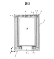
図2は本発明による液晶表示装置の第2実施例を説明する液晶表示パネル側から見た平面図である。図1と同一参照符号は同一機能部分に対応する。図1で説明した前記実施例では樹脂スペーサの第1部分を構成する突起を金属フレーム1の長辺側に設けている。これに対し、本実施例では、金属フレーム1の短辺側に突起2cと突起2dを設け、クッション部4a,4bを長辺側に設けたものである。
【0030】
図2の下側の短辺で開口1aの両側に有する突起2cは上側の短辺に有する突起2dより若干液晶表示パネル5方向の長さが長くなっているが、この長さは特に限定されるものではなく、弾性変形とその反発力が液晶パネル5を固定するために要するものであればよい。この構成とした金属フレーム1で液晶表示装置を一体化する場合、先ず液晶パネル5の下辺を樹脂スペーサの第1部分2の突起2cの腹(当該突起2cの液晶表示パネルとの固定側端)に押しつけ、弾性変形させて撓ませる。
【0031】
この状態で液晶パネル5の短辺の他方(図2では上辺)を金属フレーム1の図の上辺にある樹脂スペーサの第1部分2の突起2dと対向させてはめ込み、上記押しつけ力を解除する。これにより、液晶表示パネル5の短辺の他方は突起2cの弾性変形の反発力で突起2dに当接し、固定保持される。なお、液晶表示パネル5の長辺側のそれぞれはクッション部4c,4dに対向し、外からの衝撃が加わった場合に上記長辺がクッション部4c,4dの緩衝力で印加される衝撃が緩和される。本実施例においても、樹脂スペーサの第1部分2の突起2a,3b,2c,2d、および第3部分4は、対向辺で位置を変えても良いことは言うまでもない。
【0032】
樹脂スペーサの樹脂材料は、前記実施例と同様に光反射率が高いものを使用することで導光板6から漏れる光を液晶表示パネル5の照明光として有効に利用して輝度の低下を回避できるようにする。光反射率は70%以上であることが望ましく、酸化チタンなどを混入した、所謂白色樹脂とする。樹脂スペーサの第2部分の構成および他の部分の構成は図1に準じたものとなっている。
【0033】
本実施例により、従来の如く液晶表示パネルや導光板を位置決めし保持するための樹脂モールドを使用しないため、液晶表示装置全体の薄型・軽量化が実現できる。また、金属フレームから液晶表示パネルや導光板に伝達される外部衝撃は樹脂スペーサによって吸収または緩和され、外部衝撃による液晶表示パネルのダメージを大きく低減することができる。さらに、樹脂スペーサを高反射率の樹脂材料で成型したことで導光板からの光を有効利用して輝度低下が回避される。
【0034】
図3は本発明による液晶表示装置の第3実施例を説明する図1の(c)に相当する断面図である。図1および図2と同一参照符号は同一機能部分に対応する。本実施例は、図1および図2に示した樹脂スペーサの第3部分4のY方向クッション部4a,4bと導光板6のY方向圧接部3c,3dとを一体化したものに相当し、液晶表示パネル側から見た平面図は図1の(a)と同様である。また、図2の実施例における樹脂スペーサにも同様に適用できる。
【0035】
液晶表示パネル5と導光板6を外部衝撃から保護する緩衝材であるクッション部4a,4bと圧接部3c,3dは液晶表示パネルを保持し固定する第1部分2の突起2a乃至2dのように撓み性が要求されない。したがって、本実施例のように、クッション部4a,4bと圧接部3c,3dを一体化しても本来の機能をそれ程損ずることはない。
【0036】
本実施例によっても、液晶表示装置全体の薄型・軽量化が実現できる。また、金属フレームから液晶表示パネルや導光板に伝達される外部衝撃は樹脂スペーサによって吸収または緩和され、外部衝撃による液晶表示パネルのダメージを大きく低減することができる。さらに、樹脂スペーサを高反射率の樹脂材料で成型したことで導光板からの光を有効利用して輝度低下が回避される。
【0037】
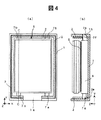
図4は本発明による液晶表示装置の第4実施例の説明図であり、同図(a)は液晶表示パネル側から見た平面図、同(b)は同(a)のC−C線に沿った断面図を示す。本実施例でも、金属フレーム1の内壁面にわたって樹脂スペーサ2が溶着あるいは射出成型で固定されている。この樹脂スペーサ2は高反射率の樹脂材料で成型され、主として導光板6の光漏れによる輝度低下を抑制するために設けられるが、液晶表示パネル5や導光板6を外部衝撃から保護する機能もある。
【0038】
バックライトを構成する導光板6の平行する二辺(ここでは、短辺)のそれぞれには爪7a、7bを有する。本実施例の爪は各短辺に二つ宛有する。この爪は導光板に一体形成されるが、別個の部品として接着してもよい。一方、樹脂スペーサ2には上記爪7a、7bに対応した位置に爪受2e,2fが形成されており、この爪受2e,2fに導光板6の爪7a、7bを嵌合させることで導光板6を所定の位置に固定する。液晶表示パネル5は両面粘着テープ8で導光板6に固定される。
【0039】
なお、図4の上側に示したように、金属フレーム1の樹脂スペーサ2の爪受に対応する位置にも爪受け1bを設けることで、導光板6の固定をさらに強固にすることもできる。また、本実施例における導光板6の固定構造を前記図1乃至図3の実施例に適用してもよく、さらに、液晶表示パネル5の固定保持構造を前記図1乃至図3の実施例と同様の構造とすることもできる。
【0040】
本実施例は、前記の各実施例に比べて、構成がより簡素化されたことにより、液晶表示装置全体の薄型・軽量化が容易であり、導光板からの光の有効利用も行えることで輝度低下が回避される。また、金属フレームから導光板に伝達される外部衝撃は樹脂スペーサによって吸収または緩和され、導光板に両面粘着テープで固定した液晶表示パネルのダメージも低減することができる。
【0041】
図5は本発明による液晶表示装置の第5実施例を説明する図1の(c)に相当する断面図である。図1乃至図4と同一参照符号は同一機能部分に対応する。本実施例は、図3および図4と同様に金属フレーム1の内壁面にわたって樹脂スペーサ2が溶着あるいは射出成型で固定されている。この樹脂スペーサ2は高反射率の樹脂材料で成型され、同様に主として導光板6の光漏れによる輝度低下を抑制するために設けられるが、液晶表示パネル5や導光板6を外部衝撃から保護する機能もある。
【0042】
バックライトを構成する導光板6の平行する二辺(ここでは、短辺)のそれぞれには爪7a、7bを有する。本実施例の爪は各短辺に二つ宛有する。この爪は図4の実施例と同様に導光板6に一体形成されるが、別個の部品として接着してもよい。一方、樹脂スペーサ2には上記爪7a、7bに対応した位置に係止突起3e,3fを有する。そして、この係止突起3e,3fに導光板6の爪7a、7bを係止して当該導光板6を所定の位置に固定する。他の構成については図4の実施例と同様である。
【0043】
本実施例も第4実施例と同様に、第1乃至第3実施例に比べて構成がより簡素化されたことにより、液晶表示装置全体の薄型・軽量化が容易であり、導光板からの光の有効利用も行えることで輝度低下が回避される。また、金属フレームから導光板に伝達される外部衝撃は樹脂スペーサによって吸収または緩和され、導光板に両面粘着テープで固定した液晶表示パネルのダメージも低減することができる。
【0044】
図6は本発明による液晶表示装置の第6実施例を説明する図1の(c)に相当する断面図である。図1乃至図5と同一参照符号は同一機能部分に対応する。本実施例は、図3乃至図5と同様に金属フレーム1の内壁面にわたって樹脂スペーサ2が溶着あるいは射出成型で固定されている。この樹脂スペーサ2は高反射率の樹脂材料で成型され、同様に主として導光板6の光漏れによる輝度低下を抑制するために設けられるが、液晶表示パネル5や導光板6を外部衝撃から保護する機能もある。
【0045】
導光板6の上に液晶表示パネル5が積層されている。樹脂スペーサの第1部分2は第2部分3よりも液晶表示パネル5側に厚く形成されている。この第1部分2と第2部分3の間にある段差で液晶表示パネル5を保持し固定している。第1部分2の厚さにもよるが、第1部分2と第2部分3を異なる樹脂で形成し、第1部分2を軟質樹脂とすることで液晶表示パネル5の装着を容易にすることができる。
【0046】
金属フレームの底部の一部にはパネル及び導光板の衝撃緩和及び位置決めのために下部樹脂スペーサ10が形成されている。またこの下部樹脂スペーサ10を設けることにより、導光板の下にパネルにつながるフレキシブル回路基板を配置することができる。また、パネルの保持構造を図7の構成としてもよい。樹脂スペーサの第1部分2と第2部分3の間にある段差部により導光板を保持した。液晶パネルは導光板に両面粘着テープで固定した。液晶パネルと導光板を両面粘着テープで固定してあるので、液晶パネル又は導光板のどちらか一方を樹脂スペーサで固定すればよい。
【0047】
本実施例も構成がより簡素化されたことにより、液晶表示装置全体の薄型・軽量化が容易であり、導光板からの光の有効利用も行えることで輝度低下が回避される。また、金属フレームから導光板に伝達される外部衝撃は樹脂スペーサによって吸収または緩和され、導光板に両面粘着テープで固定した液晶表示パネルのダメージも低減することができる。導光板の端面と樹脂スペーサの第2部分3とは隙間Dだけ離れている。隙間Dの間隔を調節することで、導光板内における光の干渉を抑制でき、導光板の輝度むらを抑制できる。
【0048】
図8、図9は本発明による液晶表示装置の第7実施例を説明する樹脂スペーサの形状例の要部断面図である。図8は断面が略コ字状の樹脂スペーサであり、第1の部分2を第2の部分3よりも軟質の樹脂で形成したものである。液晶表示パネルを装着する際には、第1の部分2は矢印で示したように変形し、第2部分3との間の溝23に液晶表示パネルを嵌合させて保持する。また、図9は上記と同様の断面が略コ字状の樹脂スペーサであるが、第1部分2と第2部分3は同一の樹脂で形成されている。そして、第1部分2の液晶表示パネル側の突出量を第2部分よしも小さくして液晶表示パネルの挿入を可能とした。
【0049】
導光板の端面は樹脂スペーサの第2部分3と対向して配置されるため、導光板端面からの光の漏洩を抑制できる。また導光板の端面と樹脂スペーサの間隔を調整することで、導光板内における光の干渉を抑制でき、導光板の輝度むらを抑制できる。
【0050】
上記の各構成を前記した各実施例の樹脂スペーサに代えることでも、上記の各実施例による輝度向上や導光板および液晶表示パネルの保持と耐外部衝撃性の効果を得ることができる。
【0051】
図10は本発明による液晶表示装置の第8実施例を説明する図6と同様の断面図である。本実施例は、前記した樹脂モールドを有する液晶表示装置に本発明を適用したものであり、特に小型化を目的としない液晶表示装置への適用例の一つである。導光板6と液晶表示パネル5は既知のように樹脂モールド9に収容して一体化されている。金属シールド1の内面には図6における樹脂スペーサに近似した形状を有する樹脂スペーサ2が前記の各実施例と同様に固定されている。
【0052】
すなわち、この樹脂シールド2の金属フレーム1の開放端部分に対応する場所に収容する樹脂モールド9方向に突出した係合突起24を有している。導光板6と液晶表示パネル5を内蔵した樹脂モールド9は、上記係合突起24を弾性変形させて金属フレーム1に挿入する。その後、係合突起24が元の位置に戻ることで樹脂モールド9は金属フレーム1に固定される。なお、この構成では、樹脂スペーサ2はクッション材としての機能も有し、液晶表示装置の全体を外部衝撃から保護する。
【0053】
図11は本発明の第9実施例を説明するための液晶表示装置の断面図である。なお、図11では構成の理解を容易にするために単なる線画とした。図11の液晶表示装置は、第1の液晶パネル5および導光板6の背面に第2の液晶パネル51及び導光板62を配置した。金属フレーム1は、底フレーム部13と、底フレーム部13から一方の垂直方向に延びる第1側壁部11と、底フレーム部13から他の一方に垂直方向に延びる第2側壁部12とからなる。また金属フレーム1は、底フレーム部13と第1側壁部11とにより形成される空間に第1の液晶パネル5及び導光板6を収納し、底フレーム部13と第2側壁部12とにより形成される空間に第2の液晶パネル51及び導光板61を収納する。
【0054】
金属フレーム1は第1の液晶パネル用のフレームと第2の液晶パネル用のフレームとが一体に形成されている。第1側壁部11には樹脂スペーサ2が設けられ、第2側壁部12には樹脂スペーサ21が設けられている。液晶パネル及び導光板の保持機構は図4と同じ構成とした。本実施例により、第1の液晶表示装置の背面に第2の液晶表示装置を配置しても、液晶表示装置全体の厚さを薄くすることができる。また、液晶パネル及び導光板の保持機構を図5と同じ構成としてもよい。
【0055】
図12は2つの液晶パネルを背面に配置した液晶表示装置に図5のパネル保持機構を適用した液晶表示装置の断面図である。なお、図12でも構成の理解を容易にするために単なる線画とした。また液晶パネルの保持機構として、樹脂モールドを使用しない他の実施例を使用してもよい。
【0056】
本発明は、以上の各実施例の構成を組み合わせることも含み、液晶表示パネルのサイズやその駆動回路基板の構成、駆動入力手段の配置構造等に応じて最適な組み合わせを選択することにより、本発明の効果を最大限に発揮させることが可能である。
【0057】
【発明の効果】
以上の実施例により説明したように、本発明によれば、液晶表示装置全体の薄型・軽量化が実現でき、また金属フレームから液晶表示パネルや導光板に伝達される外部衝撃を緩和して液晶表示パネル等へのダメージを回避できる。また、樹脂スペーサの形状あるいは物理特性を設定することによって液晶表示パネルの組み立てが容易となり、かつその脱出の防止効果を得ることができる。さらに、樹脂スペーサを高反射率の樹脂材料で成型したことで導光板からの光を有効利用して輝度低下を回避した高輝度の液晶表示装置を提供できる。
【0058】
【図面の簡単な説明】
【図1】本発明による液晶表示装置の第1実施例の説明図である。
【図2】本発明による液晶表示装置の第2実施例を説明する液晶表示パネル側から見た平面図である。
【図3】本発明による液晶表示装置の第3実施例を説明する図1の(c)に相当する断面図である。
【図4】本発明による液晶表示装置の第4実施例の説明図である。
【図5】本発明による液晶表示装置の第5実施例を説明する図1の(c)に相当する断面図である。
【図6】本発明による液晶表示装置の第6実施例を説明する図1の(c)に相当する断面図である。
【図7】本発明による液晶表示装置の第6実施例の変形例を説明する図1の(c)に相当する断面図である。
【図8】本発明による液晶表示装置の第7実施例を説明する樹脂スペーサの形状例の要部断面図である。
【図9】本発明による液晶表示装置の第7実施例の変形例を説明する樹脂スペーサの形状例の要部断面図である。
【図10】本発明による液晶表示装置の第8実施例を説明する図6と同様の断面図である。
【図11】本発明の第9実施例を説明するための液晶表示装置の断面図である。
【図12】2つの液晶パネルを背面に配置した液晶表示装置に図5のパネル保持機構を適用した液晶表示装置の断面図である。
【符号の説明】
1・・・・金属フレーム、2・・・・樹脂スペーサの第1部分、3・・・・樹脂スペーサの第2部分、4・・・・樹脂スペーサの第3部分、5・・・・液晶表示パネル、6・・・・バックライトを構成する導光板、2a,3b,2c,2d・・・・樹脂スペーサの突起、3a,3b,3c,3d・・・・圧接部、7a,7b・・・・爪、8・・・・両面粘着テープ、9・・・・樹脂モールド。[0001]
BACKGROUND OF THE INVENTION
The present invention relates to a liquid crystal display device in which a liquid crystal display panel and a backlight, which is an illumination light source, are installed on the back and housed integrally in a metal frame. In particular, the effective display area is expanded, and the backlight is reduced in size and weight. The present invention relates to a liquid crystal display device in which luminance is improved by effectively using illumination light.
[0002]
The liquid crystal display device forms an electronic latent image on a liquid crystal display panel, and irradiates illumination light to visualize the electronic latent image. Known are those that use external light as illumination light, and those that incorporate an illumination light source that irradiates light on the back or front of a liquid crystal display panel. Many liquid crystal display devices used as display means for small electronic terminals such as cellular phones use outside light, which is usually known as a reflective type, for reasons of weight reduction and power consumption. However, in recent years, an increasing number of liquid crystal display panels that incorporate an illumination light source have been used for color display and image quality improvement.
[0003]
As this type of illumination light source, a front light type in which a light source is installed on the front side of the liquid crystal display panel and a backlight type in which a light source is installed on the back side of the liquid crystal display panel are mainly used. In particular, in the case of using an active matrix type color liquid crystal display panel, a backlight that can easily perform uniform illumination over the entire surface of the display area and obtain high-intensity illumination light is often used.
[0004]
[Prior art]
There are also various types of backlights, a direct type in which the light source is installed directly under the back of the liquid crystal display panel, and a light guide plate laminated on the back of the liquid crystal display panel, and a linear lamp or light emitting diode at the edge of the light guide plate There are light sources such as side edge type. In particular, many small-screen electronic terminals are provided with a side-edge type backlight in order to reduce the thickness and weight. In a backlight type liquid crystal display device using such a light guide plate, the liquid crystal display panel and the light guide plate are stacked and housed in a metal frame to be integrated.
[0005]
At that time, the liquid crystal display panel and the light guide plate were housed in a resin frame-shaped molding material (resin mold) in order to fix the liquid crystal display, protect it from external impact, and to reduce the luminance factor of the backlight. It was in the metal frame above. Therefore, the effective display area of the liquid crystal display panel is limited at the inner edge of the resin mold. In addition, in order to prevent the light propagating inside the light guide plate from leaking from the edge of the light guide plate and emitting to the liquid crystal display panel side, a reflective tape is attached to the edge of the light guide plate, Reflective material was applied. As conventional techniques for protecting a liquid crystal panel from external impact, there are techniques disclosed in Japanese Patent Application Laid-Open Nos. 7-283560, 8-286623, and 9-5722.
[0006]
[Problems to be solved by the invention]
In general, since a resin mold is an injection-molded product, a minimum thickness of about 0.5 mm is required at the side wall and bottom surface due to molding restrictions. Furthermore, a fixing mechanism for fixing the metal frame and the resin mold is also required, leading to an increase in cost of the resin mold molding die, or the fixing mechanism is lost during assembly, resulting in a decrease in yield. In addition, the manufacturing process is complicated when a reflective tape is applied to the edge of the light guide plate or a reflective material is applied. These have become one of the bottleneck for expanding the effective display area and reducing the thickness and weight.
[0007]
Therefore, the liquid crystal display panel and the light guide plate may be directly stored in the metal frame without using a resin mold. However, since the substrate of the liquid crystal display panel is usually made of a glass material, a buffer structure is required between the substrate and the metal frame. If the reflection tape is not applied to the edge of the light guide plate or the reflection material is omitted, the amount of light emitted decreases.
[0008]
The object of the present invention is to increase the effective display area without reducing the amount of emitted light, without using a resin mold, and without applying a reflective tape or applying a reflective material to the edge of the light guide plate. It is an object of the present invention to provide a liquid crystal display device that is made easy.
[0009]
[Means for Solving the Problems]
In order to achieve the above object, in the present invention, a thin resin material having elasticity is integrated into a resin spacer inside a metal frame, and a liquid crystal display panel is fixed using the elasticity of the resin spacer. In addition, the resin spacer is made of a highly reflective resin material, and light from the light guide plate is effectively used to avoid a decrease in luminance.
[0010]
By adopting such a configuration, the external impact transmitted from the metal frame to the liquid crystal display panel and the light guide plate is reduced as well as reducing the thickness and weight of the entire liquid crystal display device. Moreover, the escape of the liquid crystal display panel is prevented by setting the shape or physical characteristics of the resin spacer. Further, the resin spacer is molded from a resin material having a high reflectivity, so that the light from the light guide plate is effectively used to avoid a decrease in luminance. A typical configuration of the liquid crystal display device according to the present invention will be described as follows.
[0011]
(1) a liquid crystal display panel, a light guide plate installed on the back surface of the liquid crystal display panel, a metal frame having a frame-like side wall and housing the liquid crystal display panel and the light guide plate, and two parallel liquid crystal display panels A resin spacer integral with the metal frame is provided between each of the sides and the side wall of the metal frame,
The resin spacer is a high reflectance resin, and the liquid crystal display panel is accommodated in the metal frame by elastic deformation, and the liquid crystal display panel is held on the metal frame by a repulsive force of the elastic deformation.
[0012]
(2) In (1), the resin spacer is provided with a first part for holding the liquid crystal display panel with a repulsive force of the elastic deformation and a second part for holding the light guide plate in a predetermined position, The amount of elastic deformation of the first part is larger than that of the second part.
[0013]
(3) In (2), the first portion is a protrusion formed discontinuously along the side of the liquid crystal display panel, and the protrusion is bent when the edge of the liquid crystal display panel is pressed. Then, elastic deformation was caused, and the stored liquid crystal display panel was fixed by the repulsive force of the elastic deformation.
[0014]
In (4) and (2), the first portion and the second portion are made of resins having different elastic deformation amounts.
[0015]
(5) a liquid crystal display panel, a light guide plate installed on the back surface of the liquid crystal display panel, a metal frame having a frame-like side wall and housing the liquid crystal display panel and the light guide plate, and two parallel liquid crystal display panels A resin spacer integral with the metal frame is provided between each of the sides and the side wall of the metal frame,
The resin spacer is made of a highly reflective resin, and a claw is provided on an edge of the light guide plate facing the resin spacer, a claw holder is provided on the resin spacer, and the claw is engaged with the claw receiver to guide the guide. An optical plate is fixed at a predetermined position of the metal frame, and the liquid crystal display panel is accommodated in the metal frame by elastic deformation,
The liquid crystal display panel was held on the metal frame by the repulsive force of the elastic deformation.
[0016]
(6) In (5), the resin spacer is formed by a first portion that holds the liquid crystal display panel with the repulsive force of the elastic deformation and a second portion that holds the light guide plate in a predetermined position, The amount of elastic deformation of the first part was made larger than that of the second part.
[0017]
In (7) and (5), the first portion is a protrusion formed discontinuously along the side of the liquid crystal display panel, and the elastic deformation is caused by the bending of the protrusion.
[0018]
In (8) and (5), the first portion and the second portion are made of resins having different elastic deformation amounts.
[0019]
It should be noted that the present invention is not limited to the above-described configuration and the configurations of the embodiments described later, and it goes without saying that various modifications can be made without departing from the technical idea of the present invention.
[0020]
DETAILED DESCRIPTION OF THE INVENTION
Embodiments of the present invention will be described below in detail with reference to the drawings of the embodiments. FIG. 1 is an explanatory view of a first embodiment of a liquid crystal display device according to the present invention, in which FIG. 1 (a) is a plan view seen from the liquid crystal display panel side, and FIG. 1 (b) is an AA line of FIG. (C) is sectional drawing along the BB line of the same (a). In FIG. 1,
[0021]
The
[0022]
One end of the
[0023]
Resins having different hardness were used for the
[0024]
The assembly of a liquid crystal display device using a metal frame in which such resin spacers are integrated is performed according to the following procedure. First, the
[0025]
In this state, the other long side (right side in FIG. 1) of the liquid
[0026]
As the resin material of the resin spacer, a material having a high light reflectance is used so that light leaking from the
[0027]
In the liquid
[0028]
According to this embodiment, since the resin mold for positioning and holding the liquid crystal display panel and the light guide plate is not used as in the prior art, the entire liquid crystal display device can be reduced in thickness and weight. Further, the external impact transmitted from the metal frame to the liquid crystal panel or the light guide plate is absorbed or alleviated by the resin spacer, and the damage of the liquid crystal display panel due to the external impact can be greatly reduced. Furthermore, since the resin spacer is molded from a resin material having a high reflectance, the light from the light guide plate is effectively used, and a reduction in luminance is avoided.
[0029]
FIG. 2 is a plan view seen from the liquid crystal display panel side for explaining a second embodiment of the liquid crystal display device according to the present invention. The same reference numerals as those in FIG. 1 correspond to the same functional parts. In the embodiment described with reference to FIG. 1, the protrusion constituting the first portion of the resin spacer is provided on the long side of the
[0030]
The
[0031]
In this state, the other short side (upper side in FIG. 2) of the
[0032]
As the resin material of the resin spacer, a material having a high light reflectance is used as in the above embodiment, so that the light leaking from the
[0033]
According to this embodiment, since the resin mold for positioning and holding the liquid crystal display panel and the light guide plate is not used as in the prior art, the entire liquid crystal display device can be reduced in thickness and weight. Further, the external impact transmitted from the metal frame to the liquid crystal display panel or the light guide plate is absorbed or alleviated by the resin spacer, so that damage to the liquid crystal display panel due to the external impact can be greatly reduced. Furthermore, since the resin spacer is molded from a resin material having a high reflectance, the light from the light guide plate is effectively used, and a reduction in luminance is avoided.
[0034]
FIG. 3 is a sectional view corresponding to FIG. 1C for explaining a third embodiment of the liquid crystal display device according to the present invention. 1 and 2 correspond to the same functional parts. The present embodiment corresponds to a combination of the Y-
[0035]
The
[0036]
Also according to this embodiment, the entire liquid crystal display device can be reduced in thickness and weight. Further, the external impact transmitted from the metal frame to the liquid crystal display panel or the light guide plate is absorbed or alleviated by the resin spacer, so that damage to the liquid crystal display panel due to the external impact can be greatly reduced. Furthermore, since the resin spacer is molded from a resin material having a high reflectance, the light from the light guide plate is effectively used, and a reduction in luminance is avoided.
[0037]
4A and 4B are explanatory views of a fourth embodiment of the liquid crystal display device according to the present invention. FIG. 4A is a plan view seen from the liquid crystal display panel side, and FIG. 4B is a CC line of FIG. Sectional drawing along is shown. Also in this embodiment, the
[0038]
Each of two parallel sides (here, short sides) of the
[0039]
As shown in the upper side of FIG. 4, the
[0040]
In this embodiment, the configuration is further simplified compared to the above-described embodiments, so that the entire liquid crystal display device can be easily reduced in thickness and weight, and the light from the light guide plate can be effectively used. Luminance reduction is avoided. In addition, external impact transmitted from the metal frame to the light guide plate is absorbed or alleviated by the resin spacer, and damage to the liquid crystal display panel fixed to the light guide plate with a double-sided adhesive tape can be reduced.
[0041]
FIG. 5 is a sectional view corresponding to FIG. 1C for explaining a fifth embodiment of the liquid crystal display device according to the present invention. The same reference numerals as those in FIGS. 1 to 4 correspond to the same functional parts. In this embodiment, the
[0042]
Each of two parallel sides (here, short sides) of the
[0043]
As in the fourth embodiment, this embodiment also has a simplified structure compared to the first to third embodiments, so that the entire liquid crystal display device can be easily reduced in thickness and weight. Luminance reduction is avoided by making effective use of light. In addition, external impact transmitted from the metal frame to the light guide plate is absorbed or alleviated by the resin spacer, and damage to the liquid crystal display panel fixed to the light guide plate with a double-sided adhesive tape can be reduced.
[0044]
FIG. 6 is a sectional view corresponding to FIG. 1C for explaining a sixth embodiment of the liquid crystal display device according to the present invention. The same reference numerals as those in FIGS. 1 to 5 correspond to the same functional parts. In this embodiment, the
[0045]
A liquid
[0046]
A
[0047]
Since the configuration of this embodiment is further simplified, it is easy to reduce the thickness and weight of the entire liquid crystal display device, and it is possible to effectively use light from the light guide plate, thereby avoiding a decrease in luminance. In addition, external impact transmitted from the metal frame to the light guide plate is absorbed or alleviated by the resin spacer, and damage to the liquid crystal display panel fixed to the light guide plate with a double-sided adhesive tape can be reduced. The end face of the light guide plate and the
[0048]
FIG. 8 and FIG. 9 are cross-sectional views of essential parts of a resin spacer shape example for explaining a seventh embodiment of the liquid crystal display device according to the present invention. FIG. 8 shows a resin spacer having a substantially U-shaped cross section, in which the
[0049]
Since the end surface of the light guide plate is disposed to face the
[0050]
By replacing the above-described configurations with the resin spacers of the above-described embodiments, it is possible to obtain the effects of improving luminance, holding the light guide plate and the liquid crystal display panel, and resistance to external impacts according to the above-described embodiments.
[0051]
FIG. 10 is a sectional view similar to FIG. 6 for explaining an eighth embodiment of the liquid crystal display device according to the present invention. In this embodiment, the present invention is applied to a liquid crystal display device having the above-described resin mold, and is one example of application to a liquid crystal display device that is not particularly aimed at miniaturization. The
[0052]
That is, the
[0053]
FIG. 11 is a cross-sectional view of a liquid crystal display device for explaining a ninth embodiment of the present invention. In FIG. 11, a simple line drawing is used for easy understanding of the configuration. In the liquid crystal display device of FIG. 11, the second
[0054]
In the
[0055]
12 is a cross-sectional view of a liquid crystal display device in which the panel holding mechanism of FIG. 5 is applied to a liquid crystal display device in which two liquid crystal panels are arranged on the back surface. It should be noted that FIG. 12 also uses a simple line drawing for easy understanding of the configuration. Moreover, you may use the other Example which does not use a resin mold as a holding mechanism of a liquid crystal panel.
[0056]
The present invention includes combining the configurations of the above-described embodiments, and by selecting an optimal combination according to the size of the liquid crystal display panel, the configuration of the drive circuit board, the arrangement structure of the drive input means, and the like. It is possible to maximize the effects of the invention.
[0057]
【The invention's effect】
As described in the above embodiments, according to the present invention, the entire liquid crystal display device can be reduced in thickness and weight, and the liquid crystal can be reduced by reducing the external impact transmitted from the metal frame to the liquid crystal display panel and the light guide plate. Damage to the display panel can be avoided. Further, by setting the shape or physical characteristics of the resin spacer, the assembly of the liquid crystal display panel can be facilitated, and the effect of preventing the escape can be obtained. Furthermore, by molding the resin spacer with a highly reflective resin material, it is possible to provide a high-brightness liquid crystal display device that effectively uses light from the light guide plate and avoids a reduction in luminance.
[0058]
[Brief description of the drawings]
FIG. 1 is an explanatory diagram of a first embodiment of a liquid crystal display device according to the present invention.
FIG. 2 is a plan view seen from the liquid crystal display panel side for explaining a second embodiment of the liquid crystal display device according to the present invention;
FIG. 3 is a cross-sectional view corresponding to FIG. 1C for explaining a third embodiment of the liquid crystal display device according to the present invention.
FIG. 4 is an explanatory diagram of a fourth embodiment of a liquid crystal display device according to the present invention.
FIG. 5 is a cross-sectional view corresponding to FIG. 1C for explaining a fifth embodiment of the liquid crystal display device according to the present invention;
FIG. 6 is a cross-sectional view corresponding to FIG. 1C for explaining a sixth embodiment of the liquid crystal display device according to the present invention.
FIG. 7 is a cross-sectional view corresponding to FIG. 1C for explaining a modification of the sixth embodiment of the liquid crystal display device according to the present invention.
FIG. 8 is a cross-sectional view of an essential part of a resin spacer shape example illustrating a seventh embodiment of the liquid crystal display device according to the present invention.
FIG. 9 is a cross-sectional view of an essential part of a resin spacer shape example illustrating a modification of the seventh embodiment of the liquid crystal display device according to the present invention.
FIG. 10 is a cross-sectional view similar to FIG. 6 for explaining an eighth embodiment of the liquid crystal display device according to the present invention.
FIG. 11 is a cross-sectional view of a liquid crystal display device for explaining a ninth embodiment of the present invention.
12 is a cross-sectional view of a liquid crystal display device in which the panel holding mechanism of FIG. 5 is applied to a liquid crystal display device in which two liquid crystal panels are arranged on the back surface.
[Explanation of symbols]
DESCRIPTION OF
Claims (10)
前記樹脂スペーサは高反射率樹脂であり、弾性変形の反発力で前記液晶表示パネルを前記金属フレームに保持することを特徴とする液晶表示装置。A liquid crystal display panel, the light guide plate attached to the back surface of the liquid crystal display panel, a metal frame for accommodating said has a frame-like side wall liquid crystal display panel and the light guide plate, parallel to two sides of the liquid crystal display panel and a resin spacer integrally with the metal frame provided between the the side wall of the metal frame, respectively,
The resin spacer is Ri high reflectance resin der, a liquid crystal display device, characterized in that for holding the liquid crystal display panel to the metal frame in repulsive force of the elastic deformation.
前記樹脂スペーサは高反射率樹脂であり、
前記導光板は前記樹脂スペーサと対向する端縁に爪を有し、
前記樹脂スペーサは、前記導光板の前記爪に係合して前記導光板を金属フレームの所定位置に固定する爪受けを有することを特徴とする液晶表示装置。A liquid crystal display panel, the light guide plate attached to the back surface of the liquid crystal display panel, a metal frame for accommodating said has a frame-like side wall liquid crystal display panel and the light guide plate, parallel to two sides of the liquid crystal display panel and a resin spacer integrally with the metal frame provided between the the side wall of the metal frame, respectively,
The resin spacer is a highly reflective resin,
The light guide plate have a nail edge facing the resin spacer,
The liquid crystal display device , wherein the resin spacer includes a claw receiver that engages with the claw of the light guide plate and fixes the light guide plate at a predetermined position of the metal frame .
前記樹脂スペーサは、前記液晶表示パネルの前面側で前記液晶表示パネルを係止する突出部を有し、
前記樹脂スペーサの前記突出部は、前記樹脂スペーサの前記導光板と前記金属フレ−ムの側壁との間に設けられた部分よりも軟質の樹脂であることを特徴とする液晶表示装置。A liquid crystal display panel; a light guide plate installed on a back surface of the liquid crystal display panel; a metal frame having a frame-shaped side wall and housing the liquid crystal display panel and the light guide plate; and two parallel sides of the liquid crystal display panel A resin spacer integral with the metal frame provided between each of the metal frame and the side wall of the metal frame, and between the light guide plate and the side wall of the metal frame,
The resin spacer has a protrusion for locking the liquid crystal display panel on the front side of the liquid crystal display panel,
The liquid crystal display device, wherein the protruding portion of the resin spacer is a softer resin than a portion provided between the light guide plate of the resin spacer and a side wall of the metal frame.
Priority Applications (5)
| Application Number | Priority Date | Filing Date | Title |
|---|---|---|---|
| JP2002001204A JP3891843B2 (en) | 2002-01-08 | 2002-01-08 | Liquid crystal display |
| KR10-2002-0080533A KR100523472B1 (en) | 2002-01-08 | 2002-12-17 | Liquid crystal display device |
| US10/321,596 US6734928B2 (en) | 2002-01-08 | 2002-12-18 | Liquid crystal display device |
| TW091137135A TWI316150B (en) | 2002-01-08 | 2002-12-24 | Liquid crystal display device |
| CNB031010474A CN1210601C (en) | 2002-01-08 | 2003-01-08 | Liquid crystal display |
Applications Claiming Priority (1)
| Application Number | Priority Date | Filing Date | Title |
|---|---|---|---|
| JP2002001204A JP3891843B2 (en) | 2002-01-08 | 2002-01-08 | Liquid crystal display |
Publications (3)
| Publication Number | Publication Date |
|---|---|
| JP2003202550A JP2003202550A (en) | 2003-07-18 |
| JP2003202550A5 JP2003202550A5 (en) | 2005-07-28 |
| JP3891843B2 true JP3891843B2 (en) | 2007-03-14 |
Family
ID=19190588
Family Applications (1)
| Application Number | Title | Priority Date | Filing Date |
|---|---|---|---|
| JP2002001204A Expired - Fee Related JP3891843B2 (en) | 2002-01-08 | 2002-01-08 | Liquid crystal display |
Country Status (5)
| Country | Link |
|---|---|
| US (1) | US6734928B2 (en) |
| JP (1) | JP3891843B2 (en) |
| KR (1) | KR100523472B1 (en) |
| CN (1) | CN1210601C (en) |
| TW (1) | TWI316150B (en) |
Families Citing this family (107)
| Publication number | Priority date | Publication date | Assignee | Title |
|---|---|---|---|---|
| TW200408853A (en) * | 2002-11-18 | 2004-06-01 | Compal Electronics Inc | Panel protection device for a liquid crystal display panel |
| JP3711987B2 (en) * | 2003-03-27 | 2005-11-02 | セイコーエプソン株式会社 | ELECTRO-OPTICAL DEVICE WITH MOUNTING CASE, PROJECTION TYPE DISPLAY DEVICE, AND MOUNTING CASE |
| US6864929B2 (en) * | 2003-04-22 | 2005-03-08 | Chunghwa Picture Tubes, Ltd. | Secure frame for light module |
| KR100580551B1 (en) * | 2003-06-19 | 2006-05-16 | 엘지.필립스 엘시디 주식회사 | Liquid crystal display module |
| CN1333289C (en) * | 2003-08-08 | 2007-08-22 | 明基电通股份有限公司 | Liquid crystal display device and its manufacturing method |
| CN1327275C (en) * | 2003-09-11 | 2007-07-18 | 友达光电股份有限公司 | Backlight assembly |
| JP4235070B2 (en) * | 2003-09-17 | 2009-03-04 | 株式会社 日立ディスプレイズ | Liquid crystal display |
| KR101191643B1 (en) * | 2003-11-26 | 2012-10-16 | 삼성디스플레이 주식회사 | Liquid Crystal Display Device Module |
| JP4859346B2 (en) * | 2004-01-30 | 2012-01-25 | セイコーエプソン株式会社 | Liquid crystal display device, method for manufacturing liquid crystal display device, electronic device |
| JP4647218B2 (en) * | 2004-02-27 | 2011-03-09 | 三菱電機株式会社 | Display device |
| JP4461869B2 (en) * | 2004-03-25 | 2010-05-12 | セイコーエプソン株式会社 | Electro-optical device and electronic apparatus |
| TWI243608B (en) * | 2004-05-31 | 2005-11-11 | Au Optronics Corp | Flat panel display |
| JP3821141B2 (en) * | 2004-06-14 | 2006-09-13 | ソニー株式会社 | Backlight device and liquid crystal display device |
| TWI241142B (en) * | 2004-08-03 | 2005-10-01 | Jemitek Electronics Corp | Flat display module |
| JP4528590B2 (en) * | 2004-09-28 | 2010-08-18 | 株式会社東芝 | Electronics |
| KR20060030379A (en) * | 2004-10-05 | 2006-04-10 | 삼성전자주식회사 | Backlight assembly and liquid crystal display device having the same |
| CN100403105C (en) * | 2004-10-07 | 2008-07-16 | 鸿富锦精密工业(深圳)有限公司 | Liquid crystal display mould set gum frame and liquid crystal display mould set |
| US20060114366A1 (en) * | 2004-12-01 | 2006-06-01 | Au Optronics Corporation | Flat-panel display apparatus |
| TWI261137B (en) | 2004-12-02 | 2006-09-01 | Au Optronics Corp | Frame and liquid crystal display module utilizing the same |
| JP4595595B2 (en) * | 2005-03-08 | 2010-12-08 | ソニー株式会社 | Backlight device and liquid crystal display device |
| JP4618108B2 (en) * | 2005-04-21 | 2011-01-26 | パナソニック株式会社 | Information processing device |
| TWI287153B (en) * | 2005-08-08 | 2007-09-21 | Au Optronics Corp | Backlight module structure |
| EP1919267B1 (en) | 2005-08-25 | 2013-06-05 | NEC Corporation | Mobile device with display unit |
| TWI287149B (en) * | 2005-08-26 | 2007-09-21 | Innolux Display Corp | Backlight module and method of manufacturing the same |
| TWI282473B (en) * | 2005-11-23 | 2007-06-11 | Chunghwa Picture Tubes Ltd | Backlight module and liquid crystal display |
| KR20070059526A (en) * | 2005-12-07 | 2007-06-12 | 삼성전자주식회사 | Dual display apparatus |
| JP2007163556A (en) * | 2005-12-09 | 2007-06-28 | Hitachi Displays Ltd | Liquid crystal display device |
| JP2007163620A (en) * | 2005-12-12 | 2007-06-28 | Hitachi Displays Ltd | Liquid crystal display device and backlight device |
| JP4911983B2 (en) * | 2006-02-08 | 2012-04-04 | 株式会社 日立ディスプレイズ | Display device |
| JP2007298622A (en) * | 2006-04-28 | 2007-11-15 | Hitachi Displays Ltd | Liquid crystal display device |
| JP2007328613A (en) * | 2006-06-08 | 2007-12-20 | Toshiba Corp | Electronic device |
| KR100722119B1 (en) * | 2006-09-20 | 2007-05-25 | 삼성에스디아이 주식회사 | Organic light emitting display device |
| KR100769425B1 (en) | 2006-09-21 | 2007-10-22 | 삼성에스디아이 주식회사 | Organic light-emitting display device |
| KR100729084B1 (en) | 2006-09-21 | 2007-06-14 | 삼성에스디아이 주식회사 | Organic light emitting diode |
| US7605880B2 (en) * | 2006-10-27 | 2009-10-20 | Chunghwa Picture Tubes, Ltd. | Liquid crystal display |
| TWI340851B (en) * | 2006-10-27 | 2011-04-21 | Chimei Innolux Corp | Display device |
| CN101256299B (en) * | 2007-02-28 | 2010-05-26 | 群康科技(深圳)有限公司 | Back light module unit as well as display device using the same |
| JP4353266B2 (en) | 2007-04-05 | 2009-10-28 | エプソンイメージングデバイス株式会社 | Electro-optical device and electronic apparatus |
| KR101409677B1 (en) * | 2007-06-20 | 2014-06-18 | 엘지디스플레이 주식회사 | Back-light Unit |
| WO2008143418A1 (en) | 2007-05-23 | 2008-11-27 | Lg Innotek Co., Ltd. | Display device |
| KR101396733B1 (en) * | 2007-05-23 | 2014-05-19 | 엘지디스플레이 주식회사 | Display Module and Method for Manufacturing Thereof |
| KR101396768B1 (en) * | 2007-07-06 | 2014-05-16 | 엘지디스플레이 주식회사 | Receiving device in display device and liquid crystal display device having the receiving container |
| JP5433940B2 (en) * | 2007-09-12 | 2014-03-05 | エプソンイメージングデバイス株式会社 | Electro-optical device and electronic apparatus |
| JP5074135B2 (en) * | 2007-09-18 | 2012-11-14 | 株式会社ジャパンディスプレイイースト | Liquid crystal display |
| JP4516106B2 (en) * | 2007-12-18 | 2010-08-04 | 東芝モバイルディスプレイ株式会社 | Flat display device and manufacturing method thereof |
| JP5536031B2 (en) * | 2008-03-31 | 2014-07-02 | コーニング インコーポレイテッド | Bezel package for sealing glass assembly and glass assembly therefor |
| CN101587262B (en) * | 2008-05-23 | 2011-06-15 | 群康科技(深圳)有限公司 | Liquid crystal display (LCD) device |
| KR101291798B1 (en) * | 2008-06-10 | 2013-07-31 | 엘지디스플레이 주식회사 | Liquid Crystal Display Module And Assembling Method Thereof |
| JP5287045B2 (en) * | 2008-08-29 | 2013-09-11 | サクサ株式会社 | Liquid crystal display |
| US7948576B2 (en) * | 2008-09-25 | 2011-05-24 | Apple Inc. | P-chassis arrangement for positioning a display stack |
| CN101725844A (en) * | 2008-11-04 | 2010-06-09 | 奇美电子股份有限公司 | Backlight module and liquid crystal display |
| JP5386941B2 (en) * | 2008-11-14 | 2014-01-15 | セイコーエプソン株式会社 | ELECTRO-OPTICAL DEVICE, MANUFACTURING METHOD THEREOF, AND ELECTRONIC DEVICE |
| JP2010151853A (en) * | 2008-12-23 | 2010-07-08 | Nippon Seiki Co Ltd | Display device |
| JP5072875B2 (en) * | 2009-02-04 | 2012-11-14 | 株式会社ジャパンディスプレイセントラル | Backlight unit and liquid crystal display device using the same |
| CN101846837B (en) * | 2009-03-25 | 2011-08-24 | 华映视讯(吴江)有限公司 | Display device |
| JP5235769B2 (en) * | 2009-04-27 | 2013-07-10 | 株式会社ジャパンディスプレイイースト | Liquid crystal display |
| TWI410719B (en) * | 2010-03-25 | 2013-10-01 | Au Optronics Corp | Panel display module and manufacture method thereof |
| TWI408442B (en) | 2010-04-15 | 2013-09-11 | Au Optronics Corp | Liquid crystal display device |
| EP2390693B1 (en) * | 2010-05-25 | 2022-11-23 | Suzhou Lekin Semiconductor Co., Ltd. | Backlight unit and display device |
| WO2011148656A1 (en) * | 2010-05-28 | 2011-12-01 | シャープ株式会社 | Display device |
| JP5564345B2 (en) * | 2010-06-30 | 2014-07-30 | 株式会社ジャパンディスプレイ | Display device |
| JP5558267B2 (en) * | 2010-08-25 | 2014-07-23 | パナソニック液晶ディスプレイ株式会社 | Liquid crystal display |
| DE202011108786U1 (en) * | 2010-09-09 | 2012-03-26 | Lg Electronics Inc. | display device |
| US20120106121A1 (en) * | 2010-10-27 | 2012-05-03 | Moungyoub Lee | Display apparatus |
| DE202011108257U1 (en) * | 2010-10-28 | 2012-03-15 | Lg Electronics Inc. | display device |
| US8319912B2 (en) | 2010-10-28 | 2012-11-27 | Lg Electronics Inc. | Display apparatus |
| JP5158177B2 (en) * | 2010-11-04 | 2013-03-06 | セイコーエプソン株式会社 | Liquid crystal display device, method for manufacturing liquid crystal display device, electronic device |
| USRE47419E1 (en) * | 2010-11-22 | 2019-06-04 | Wistron Corporation | Liquid crystal display device and electronic equipment having the same |
| KR20120071751A (en) * | 2010-12-23 | 2012-07-03 | 엘지디스플레이 주식회사 | Display device |
| CN102608772A (en) * | 2011-01-24 | 2012-07-25 | 深圳富泰宏精密工业有限公司 | Window installation fixture |
| CN202067045U (en) * | 2011-05-10 | 2011-12-07 | 深圳市华星光电技术有限公司 | Liquid crystal display device and rear shell of liquid crystal display device |
| JP2013008016A (en) | 2011-05-24 | 2013-01-10 | Sony Corp | Display unit |
| TWI462068B (en) | 2011-06-20 | 2014-11-21 | Au Optronics Corp | Organic light emitting display module and producing method thereof |
| KR101820363B1 (en) * | 2011-07-20 | 2018-01-19 | 엘지디스플레이 주식회사 | Liquid crystal display device module and method of the same |
| JP2013033108A (en) | 2011-08-01 | 2013-02-14 | Funai Electric Co Ltd | Liquid crystal module |
| TWI447482B (en) * | 2011-09-28 | 2014-08-01 | Au Optronics Corp | Display module |
| JP5705701B2 (en) * | 2011-10-18 | 2015-04-22 | 株式会社ジャパンディスプレイ | Liquid crystal display |
| US9195083B2 (en) * | 2011-10-31 | 2015-11-24 | Microsoft Technology Licensing, Llc | Impact resistant construction of an interactive device |
| TWI528133B (en) | 2012-02-13 | 2016-04-01 | 達運精密工業股份有限公司 | Display device with frame configuration |
| US20150153594A1 (en) * | 2012-06-05 | 2015-06-04 | Nec Casio Mobile Communications, Ltd. | Electronic apparatus display unit and portable terminal apparatus comprising the same |
| US20140015817A1 (en) * | 2012-07-10 | 2014-01-16 | Panasonic Corporation | Information display device |
| JP5445641B2 (en) * | 2012-08-18 | 2014-03-19 | セイコーエプソン株式会社 | Electro-optical device, method of manufacturing electro-optical device, and electronic apparatus |
| KR101957143B1 (en) * | 2012-11-06 | 2019-03-12 | 엘지디스플레이 주식회사 | Lliquid crystal display device |
| JP6312072B2 (en) * | 2012-12-26 | 2018-04-18 | 株式会社ジャパンディスプレイ | Liquid crystal display |
| US20140211507A1 (en) * | 2013-01-31 | 2014-07-31 | Innolux Corporation | Electronic device |
| CN103091879A (en) * | 2013-02-01 | 2013-05-08 | 京东方科技集团股份有限公司 | Liquid crystal display panel and display device |
| JP6226556B2 (en) * | 2013-05-14 | 2017-11-08 | キヤノン株式会社 | Image display device |
| KR20150021368A (en) * | 2013-08-20 | 2015-03-02 | 삼성디스플레이 주식회사 | Display device and method for manufacturing of the same |
| JP6349081B2 (en) * | 2013-12-10 | 2018-06-27 | Kisco株式会社 | refrigerator |
| JP2015184561A (en) * | 2014-03-25 | 2015-10-22 | ソニー株式会社 | Light guide device, image display device, and display device |
| JP2015184560A (en) | 2014-03-25 | 2015-10-22 | ソニー株式会社 | Light guide device, image display device, and display device |
| KR20150116016A (en) * | 2014-04-03 | 2015-10-15 | 삼성디스플레이 주식회사 | Botttom chassis and display device comprising the same |
| TWI554716B (en) * | 2014-06-17 | 2016-10-21 | 高雄晶傑達光電科技股份有限公司 | Fixing component for light guide plate |
| JP6548363B2 (en) * | 2014-07-10 | 2019-07-24 | 三菱電機株式会社 | Display device |
| TWI563318B (en) * | 2014-07-29 | 2016-12-21 | Young Lighting Technology Inc | Display |
| CN104298042A (en) * | 2014-09-23 | 2015-01-21 | 合肥鑫晟光电科技有限公司 | Display panel and display device |
| CN104460066B (en) * | 2014-12-26 | 2018-05-29 | 深圳市华星光电技术有限公司 | A kind of liquid crystal display |
| US9817261B2 (en) * | 2015-04-28 | 2017-11-14 | Lg Display Co., Ltd. | Curved cover for curved display and curved type display apparatus including the same |
| JP6529431B2 (en) * | 2015-12-24 | 2019-06-12 | 株式会社フジクラ | Optical element package |
| CN105676339A (en) * | 2016-02-22 | 2016-06-15 | 京东方科技集团股份有限公司 | Side-incoming type backlight unit and display device |
| KR102600188B1 (en) * | 2016-08-30 | 2023-11-08 | 엘지디스플레이 주식회사 | Liquid crystal display device |
| US10236609B2 (en) * | 2016-09-23 | 2019-03-19 | Apple Inc. | Connectors having printed circuit board tongues with reinforced frames |
| JP7343316B2 (en) * | 2018-12-17 | 2023-09-12 | 日東電工株式会社 | Image display panel with bezel, image display device and optical film with adhesive layer |
| WO2020129332A1 (en) * | 2018-12-17 | 2020-06-25 | 日東電工株式会社 | Image display panel with bezel, and image display device |
| CN111812875B (en) * | 2019-04-11 | 2023-03-28 | 苏州璨鸿光电有限公司 | Display device |
| TWI704397B (en) * | 2019-08-20 | 2020-09-11 | 眾福科技股份有限公司 | Display device |
| CN115128859A (en) * | 2021-03-24 | 2022-09-30 | 群创光电股份有限公司 | Display device |
Family Cites Families (5)
| Publication number | Priority date | Publication date | Assignee | Title |
|---|---|---|---|---|
| JP3231820B2 (en) * | 1991-12-17 | 2001-11-26 | ソニー株式会社 | Liquid crystal display |
| JP3434345B2 (en) | 1994-04-15 | 2003-08-04 | 大成プラス株式会社 | Mounting structure of plate-like body in handy type electronic equipment |
| JP3215844B2 (en) * | 1995-04-18 | 2001-10-09 | キヤノン株式会社 | Display device and method of manufacturing the display device |
| JPH095722A (en) | 1995-06-14 | 1997-01-10 | Nikko Kogyo Kk | Liquid crystal panel holding frame |
| KR100280882B1 (en) * | 1998-04-22 | 2001-03-02 | 구본준 | Slim laptop |
-
2002
- 2002-01-08 JP JP2002001204A patent/JP3891843B2/en not_active Expired - Fee Related
- 2002-12-17 KR KR10-2002-0080533A patent/KR100523472B1/en active IP Right Grant
- 2002-12-18 US US10/321,596 patent/US6734928B2/en not_active Expired - Lifetime
- 2002-12-24 TW TW091137135A patent/TWI316150B/en not_active IP Right Cessation
-
2003
- 2003-01-08 CN CNB031010474A patent/CN1210601C/en not_active Expired - Fee Related
Also Published As
| Publication number | Publication date |
|---|---|
| CN1210601C (en) | 2005-07-13 |
| US20030128307A1 (en) | 2003-07-10 |
| KR20030060761A (en) | 2003-07-16 |
| US6734928B2 (en) | 2004-05-11 |
| TW200304027A (en) | 2003-09-16 |
| JP2003202550A (en) | 2003-07-18 |
| KR100523472B1 (en) | 2005-10-24 |
| CN1431545A (en) | 2003-07-23 |
| TWI316150B (en) | 2009-10-21 |
Similar Documents
| Publication | Publication Date | Title |
|---|---|---|
| JP3891843B2 (en) | Liquid crystal display | |
| JP4311454B2 (en) | Lighting device, liquid crystal device, and electronic device | |
| US20070132909A1 (en) | Liquid crystal display device | |
| JP5207189B2 (en) | Liquid crystal display | |
| US20070252922A1 (en) | Liquid crystal display device | |
| CN108205224B (en) | Backlight and display device | |
| EP1865252B1 (en) | Spread illuminating apparatus | |
| JP2003255309A (en) | Optical unit and liquid crystal display using the same | |
| JP2002049022A (en) | Liquid crystal display device | |
| US10048524B2 (en) | Top case having outsert molding member and display device having the same | |
| WO2013161241A1 (en) | Backlight unit and liquid crystal display apparatus | |
| JPH11126033A (en) | Electro-optical device and projection type display device provided with the same | |
| JP6850948B2 (en) | Surface light source device, display device, and electronic device | |
| KR101396733B1 (en) | Display Module and Method for Manufacturing Thereof | |
| WO2012036061A1 (en) | Illumination device, display device, and television receiver | |
| US11852862B2 (en) | Backlight module including interference fit and liquid crystal display device including the same | |
| JP6025423B2 (en) | Display device | |
| JP5578559B2 (en) | Backlight unit and liquid crystal display device | |
| JP2005077755A (en) | Frame case | |
| KR101949673B1 (en) | Slim-type display module | |
| JP2008129474A (en) | Display device | |
| KR20170075464A (en) | Liquid crystal display device | |
| KR102436555B1 (en) | Backlight unit and liquid crystal display module having the same | |
| JP4299568B2 (en) | Front light unit and liquid crystal display device | |
| JP4438539B2 (en) | Display device and planar light source device |
Legal Events
| Date | Code | Title | Description |
|---|---|---|---|
| A521 | Request for written amendment filed |
Free format text: JAPANESE INTERMEDIATE CODE: A523 Effective date: 20041217 |
|
| A621 | Written request for application examination |
Free format text: JAPANESE INTERMEDIATE CODE: A621 Effective date: 20041217 |
|
| A977 | Report on retrieval |
Free format text: JAPANESE INTERMEDIATE CODE: A971007 Effective date: 20060925 |
|
| TRDD | Decision of grant or rejection written | ||
| A01 | Written decision to grant a patent or to grant a registration (utility model) |
Free format text: JAPANESE INTERMEDIATE CODE: A01 Effective date: 20061121 |
|
| A61 | First payment of annual fees (during grant procedure) |
Free format text: JAPANESE INTERMEDIATE CODE: A61 Effective date: 20061205 |
|
| R150 | Certificate of patent or registration of utility model |
Free format text: JAPANESE INTERMEDIATE CODE: R150 Ref document number: 3891843 Country of ref document: JP Free format text: JAPANESE INTERMEDIATE CODE: R150 |
|
| FPAY | Renewal fee payment (event date is renewal date of database) |
Free format text: PAYMENT UNTIL: 20101215 Year of fee payment: 4 |
|
| FPAY | Renewal fee payment (event date is renewal date of database) |
Free format text: PAYMENT UNTIL: 20101215 Year of fee payment: 4 |
|
| S531 | Written request for registration of change of domicile |
Free format text: JAPANESE INTERMEDIATE CODE: R313531 |
|
| R371 | Transfer withdrawn |
Free format text: JAPANESE INTERMEDIATE CODE: R371 |
|
| FPAY | Renewal fee payment (event date is renewal date of database) |
Free format text: PAYMENT UNTIL: 20101215 Year of fee payment: 4 |
|
| FPAY | Renewal fee payment (event date is renewal date of database) |
Free format text: PAYMENT UNTIL: 20111215 Year of fee payment: 5 |
|
| R250 | Receipt of annual fees |
Free format text: JAPANESE INTERMEDIATE CODE: R250 |
|
| FPAY | Renewal fee payment (event date is renewal date of database) |
Free format text: PAYMENT UNTIL: 20111215 Year of fee payment: 5 |
|
| S111 | Request for change of ownership or part of ownership |
Free format text: JAPANESE INTERMEDIATE CODE: R313111 |
|
| S631 | Written request for registration of reclamation of domicile |
Free format text: JAPANESE INTERMEDIATE CODE: R313631 |
|
| FPAY | Renewal fee payment (event date is renewal date of database) |
Free format text: PAYMENT UNTIL: 20111215 Year of fee payment: 5 |
|
| R350 | Written notification of registration of transfer |
Free format text: JAPANESE INTERMEDIATE CODE: R350 |
|
| FPAY | Renewal fee payment (event date is renewal date of database) |
Free format text: PAYMENT UNTIL: 20111215 Year of fee payment: 5 |
|
| S111 | Request for change of ownership or part of ownership |
Free format text: JAPANESE INTERMEDIATE CODE: R313115 Free format text: JAPANESE INTERMEDIATE CODE: R313121 |
|
| FPAY | Renewal fee payment (event date is renewal date of database) |
Free format text: PAYMENT UNTIL: 20111215 Year of fee payment: 5 |
|
| R350 | Written notification of registration of transfer |
Free format text: JAPANESE INTERMEDIATE CODE: R350 |
|
| FPAY | Renewal fee payment (event date is renewal date of database) |
Free format text: PAYMENT UNTIL: 20111215 Year of fee payment: 5 |
|
| FPAY | Renewal fee payment (event date is renewal date of database) |
Free format text: PAYMENT UNTIL: 20121215 Year of fee payment: 6 |
|
| R250 | Receipt of annual fees |
Free format text: JAPANESE INTERMEDIATE CODE: R250 |
|
| FPAY | Renewal fee payment (event date is renewal date of database) |
Free format text: PAYMENT UNTIL: 20121215 Year of fee payment: 6 |
|
| FPAY | Renewal fee payment (event date is renewal date of database) |
Free format text: PAYMENT UNTIL: 20131215 Year of fee payment: 7 |
|
| R250 | Receipt of annual fees |
Free format text: JAPANESE INTERMEDIATE CODE: R250 |
|
| R250 | Receipt of annual fees |
Free format text: JAPANESE INTERMEDIATE CODE: R250 |
|
| R250 | Receipt of annual fees |
Free format text: JAPANESE INTERMEDIATE CODE: R250 |
|
| R250 | Receipt of annual fees |
Free format text: JAPANESE INTERMEDIATE CODE: R250 |
|
| R250 | Receipt of annual fees |
Free format text: JAPANESE INTERMEDIATE CODE: R250 |
|
| R250 | Receipt of annual fees |
Free format text: JAPANESE INTERMEDIATE CODE: R250 |
|
| R250 | Receipt of annual fees |
Free format text: JAPANESE INTERMEDIATE CODE: R250 |
|
| R250 | Receipt of annual fees |
Free format text: JAPANESE INTERMEDIATE CODE: R250 |
|
| R250 | Receipt of annual fees |
Free format text: JAPANESE INTERMEDIATE CODE: R250 |
|
| S531 | Written request for registration of change of domicile |
Free format text: JAPANESE INTERMEDIATE CODE: R313531 |
|
| S533 | Written request for registration of change of name |
Free format text: JAPANESE INTERMEDIATE CODE: R313533 |
|
| R350 | Written notification of registration of transfer |
Free format text: JAPANESE INTERMEDIATE CODE: R350 |
|
| LAPS | Cancellation because of no payment of annual fees |