JP3883301B2 - Kitchen furniture cabinet structure - Google Patents
Kitchen furniture cabinet structure Download PDFInfo
- Publication number
- JP3883301B2 JP3883301B2 JP27991298A JP27991298A JP3883301B2 JP 3883301 B2 JP3883301 B2 JP 3883301B2 JP 27991298 A JP27991298 A JP 27991298A JP 27991298 A JP27991298 A JP 27991298A JP 3883301 B2 JP3883301 B2 JP 3883301B2
- Authority
- JP
- Japan
- Prior art keywords
- cabinet
- connecting member
- bottom plate
- kitchen furniture
- back plate
- Prior art date
- Legal status (The legal status is an assumption and is not a legal conclusion. Google has not performed a legal analysis and makes no representation as to the accuracy of the status listed.)
- Expired - Fee Related
Links
Images


Landscapes
- Combinations Of Kitchen Furniture (AREA)
Description
【0001】
【発明の属する技術分野】
この発明は、システムキッチンの構成要素としての流し、調理面、加熱器を備えた厨房家具、複合厨房家具、セクショナルキッチンとしての流し台、調理台、こんろ台などの台所に設置される厨房家具のキャビネット構造に係るもので、特に、背面下部に特徴を有するものである。
【0002】
【従来の技術】
特開昭50−5147号公報、実開昭58−68135号公報などに開示されているように、従来の厨房家具のキャビネット構造では、底板、背板、両側板、前面の扉からなるキャビネットを必要に応じて台輪に載せて収納部を構成するものであった。
このような従来のキャビネットでは、底板と背板は直角に組み付けられるものが殆どであった。そのため、例えば壁面に沿って給排水管、ガス管及び電気配線をしたり、壁面に近い床より立ち上げられた給排水管、ガス管を避けるためには、キャビネットの背板を手前に組み付けた別構造のキャビネットを用意する必要があった。
あるいは、従来のキャビネットを現場にて背板下端部及び底板の奥行を短くなるように切除して別途部材あるいは切断した部材を元の部材と直角となるように繋げてキャビネットの背面下部にスペースを設けるように加工することも行われていた。
【0003】
特開平10−127381号公報では、上記のような手間を避けるため、キャビネット本体の奥側下隅部に開口を設け、この開口を塞ぐ断面視ほぼL型のコーナー部材50を表裏反転自在に取り付けるようにした構造が提案されている。図5は、キャビネットの奥下隅部に配管スペースを形成するようにコーナー部材50を配置しビスにて取り付ける例を示すものである。配管スペースが不要な場合は表裏反転して取り付けることになる。
【0004】
【発明が解決しようとする課題】
予め別構造のキャビネットを製造するのは、二種類のキャビネットを用意することとなり、製造面でコスト高になっていた。
同じく、現場対応で加工する場合にも、加工の手間や部材を用意するなど作業コストが嵩み、作業品質にもばらつきが避けられなかった。
断面ほぼL型のコーナー部材を表裏反転自在に取り付けるものでは、実際の施工現場では取り付け取り外しが容易でなく取り扱いに問題が生じることが予想される。すなわち、両面が内面となる可能性があるので掃除のし易さなどから補強用のリブを設けることが難しく、部材の強度は成形肉厚によって保たせることになるので重量が嵩み、また、コーナー部材をキャビネットに設置する際の取り回しに必要なクリアランスを確保するとキャビネットの側板とコーナー部材との間に隙間が生じてしまい、これを避けるためコーナー部材を隙間が開かないような長さとすると取り回しが困難となる構造となっていた。
【0005】
【課題を解決するための手段】
この発明は、このような従来技術の課題を解決すべく開発したもので、背面下部に開口を設け、ここを別途一の繋ぎ部材にて接合するようにしたキャビネット構造で、必要に応じてキャビネットの背面下部にスペースを設けたり、設けなかったりすることでキャビネットの共通化を図ることができたのである。
また、繋ぎ部材の素材、形状、機能によって、合理的な繋ぎ部材とキャビネット構造を提供することにより、台所の厨房設備に係る配管設備工事、電気工事などの現場工事に即応することのできる厨房家具のキャビネット構造とすることができたのである。
【0006】
請求項1の発明は、厨房家具のキャビネット構造において、背板の下端部及び底板の奥行を短くして開口を設け、この開口を塞ぐ繋ぎ部材を背板及び底板の内面に取り付けて出隅、入隅を形成するようにしたものであって、繋ぎ部材を、平板として、長手方向の両側端部を背板及び底板の内面への取付辺とし、これら取付辺の間に背板と底板の隙間を出隅入隅で繋ぐときの垂直辺及び水平辺を設け、取付辺と垂直辺、水平辺との間及び垂直辺と水平辺の間を軟質材からなる折曲帯を介在させ、その他を硬質材にて一体に形成したものとし、一の繋ぎ部材で上下反転することで出隅、入隅を形成できるようにしたものである。
【0007】
請求項2の発明は、請求項1記載の厨房家具のキャビネット構造において、キャビネットの両側板の内側にL形の受け部材を取り付け、繋ぎ部材の両側端部を載せ架けるようにしたものである。
請求項3の発明は、繋ぎ部材の垂直辺及び水平辺の片面側の長手方向に、多数の補強用の突条を形成したことを特徴とするものである。
【0008】
【発明の実施の形態】
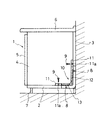
図1及び図2は、この発明に係る厨房家具のキャビネット1であるが上面の水槽、加熱器は省略している。キャビネット1は底板2、背板3、側板4、4及び前面の扉5により上面を開放し天板6を載せるもので、これらは台輪7上に載置されている。台輪7はキャビネットと一体に構成するものとしても良い。
背板3の下端部及び底板2の奥行を短くして開口を設け、この隙間を繋ぎ部材10(図3、図4参照)を取り付けて塞ぐようにしてある。
【0009】
この繋ぎ部材10は、硬質プラスチックと軟質プラスチックを一体に押出成形して得る平板であり、その長さはキャビネット1の側板4、4の間とほぼ同一で取り回しに必要なクリアランスを確保するために若干短くする。
繋ぎ部材10の長手方向の両側端部を背板3及び底板2の内面への取付辺11、11とし、これら取付辺11、11の間に背板3と底板2の隙間を出隅入隅で繋ぐときの垂直辺12及び水平辺13を設け、これらを硬質プラスチックからなる硬質材とし、これら硬質材からなる取付辺11と垂直辺12、水平辺13との間及び垂直辺12と水平辺13の間を軟質材具体的には軟質プラスチックからなる折曲帯14を介在させるようにしている。
繋ぎ部材10の垂直辺12及び水平辺13の片面側の長手方向には多数の補強用の突条15を一体に形成してある。これにより、繋ぎ部材10全体の肉厚を押えても剛性を保ち、かつ、片面を平滑面として常にキャビネット1の内面に位置させることで清掃の便宜を図ることができる。
取付辺11には適宜間隔にて抜き穴11a、11aを穿つようにし、ビス8を抜き穴11aより背板3及び底板2にねじ込み、繋ぎ部材10を固定することになる。
【0010】
図1に示すキャビネット1では、その背面下部に配管スペースが不要な場合で、まず、背板3及び底板2を延長するようなL形をなす受け部材20を側板4、4にビス8にて止め付けるようにする。次いで、繋ぎ部材10の垂直辺12と水平辺13の間の折曲帯14を、突条15がキャビネット1の外側になるように直角に曲げ、全体として側面L状となるようにし、取付辺11の抜き穴11aよりビス9をキャビネット1の底板2及び背板3にねじ込んで、繋ぎ部材10の両側端部が受け部材20に載せ架けるようにして取り付けキャビネット1の開口を出隅とするものである。
受け部材20は5mm程度の厚みを持つもので、主として繋ぎ部材10とキャビネット1の側板4、4との隙間を塞ぐ役割を果たし、補助的に取付辺11と垂直辺12及び水平辺13の間の折曲帯14による繋ぎ部材10の屈曲変形を防ぐことになる。
【0011】
図2に示すものは、キャビネット1の背面下部に配管スペース30を設けるようにするもので、図3、4に示す同じ繋ぎ部材10を図1の状態と比較すれば上下逆転し、折曲帯14、14、14にて直角に曲げて用いるもので、キャビネット1内部奥に架台を設けるような入隅の構成となる。
受け部材20は背板3及び底板2と直角をなすような逆L形をなすように配置し、この受け部材20を側板4、4にビス8にて固定する。
図1及び図2における受け部材20は同一の構成をなすもので、向きを変えて用いるものである。
繋ぎ部材10は突条15がキャビネット1の外側となるようにして、折曲帯14、14、14にて夫々直角に曲げて、その取付辺11、11を底板2及び背板3の内面に沿わせてビス9を抜き穴11aよりねじ込んで、受け部材20に載せ架けるようにして取り付けるのである。
【0012】
繋ぎ部材10をビス9にて取り付けるものとしているが、接着剤にて貼り付けるようにしてもよい。
図1における繋ぎ部材10の取り付け構造では、従来の底板と背板を直角に組み付けたものと同様なもので、キャビネットの背板3と台所の壁面の間にスペースをもって配置する場合に好適なものといえる。さらに、繋ぎ部材10になんら加工を施さないのであれば、繋ぎ部材10を固定して組み込んで現場に搬入することもできる。
図2での繋ぎ部材10の取り付け構造では、繋ぎ部材10にてキャビネット1の背面外側に配管スペース30を形成し、キャビネット1内の奥には架台を形成することになる。
【0013】
詳細な図示は省略するが、図1、図2の出隅、入隅に繋ぎ部材10を配置する場合に、この繋ぎ部材10に、給水管、給湯管、排水管、ガス管、排気管などの配管などのための孔を穿つようにし、底板2には孔加工をしないようにする。
図示しないが、電気配線のための孔を繋ぎ部材10に設けたり、蓋付きの点検口を設けることもできる。
【0014】
【発明の効果】
請求項1記載の発明では、キャビネットの背面側に開口を形成し、硬質材と軟質材を一体に構成したものを繋ぎ部材として塞ぐようにしてあるので、一の繋ぎ部材で上下反転させ、軟質材よりなる折曲帯で曲げ開口を出隅、入隅のいずれでも塞ぐことができるので、キャビネットの背面に配管スペースを備えるものと、備えないものを一種類のキャビネットとして製造することができ製品の点数を増やすことがないので、生産効率がアップし、施工現場で即応することもできることになる。
請求項2記載の発明では、請求項1記載の厨房家具のキャビネット構造において、キャビネットの両側板の内側にL形の受け部材を取り付け、繋ぎ部材の両側端部を載せ架けるようにしたので、繋ぎ部材の取り回しのためのクリアランスを確保しながら、キャビネットの側板との間を受け部材で塞ぐことができることになる。
【0015】
請求項3記載の発明では、繋ぎ部材の垂直辺及び水平辺の片面側の長手方向に、多数の補強用の突条を形成したので、全体として肉厚を押えて比較的軽くても強度を保つことができることになる。
【図面の簡単な説明】
【図1】この発明の要部断面図である。
【図2】同じくこの発明の要部断面図である。
【図3】繋ぎ部材の正面図である。
【図4】繋ぎ部材の断面図である。
【図5】従来例の取り付け状態の断面図である。
【符号の説明】
1 キャビネット
2 底板
3 背板
4 側板
5 扉
6 天板
7 台輪
10 繋ぎ部材
11 取付辺
12 垂直辺
13 水平辺
14 折曲帯
30 配管スペース[0001]
BACKGROUND OF THE INVENTION
This invention relates to kitchen furniture installed in kitchens such as sinks, cooking surfaces, kitchen furniture equipped with heaters, composite kitchen furniture, sinks as sectional kitchens, cooking tables, stovetops as components of system kitchens. It relates to a cabinet structure, and particularly has a feature in the lower part of the back surface.
[0002]
[Prior art]
As disclosed in Japanese Patent Application Laid-Open Nos. 50-5147, 58-68135, etc., the conventional cabinet structure of kitchen furniture includes a cabinet comprising a bottom plate, a back plate, both side plates, and a front door. The storage unit was configured by placing it on a pedestal as required.
In such a conventional cabinet, the bottom plate and the back plate are mostly assembled at right angles. Therefore, for example, in order to connect the water supply / drainage pipe, gas pipe and electrical wiring along the wall surface, or to avoid the water supply / drainage pipe and gas pipe raised from the floor near the wall surface, a separate structure with the back plate of the cabinet assembled in front There was a need to prepare a cabinet.
Alternatively, a conventional cabinet is cut at the site so that the lower end of the back plate and the depth of the bottom plate are shortened, and a separate member or a cut member is connected so as to be perpendicular to the original member to provide a space at the lower back of the cabinet. Processing was also performed to provide.
[0003]
In Japanese Patent Laid-Open No. 10-127381, in order to avoid the above-described trouble, an opening is provided in the lower corner of the back side of the cabinet body, and a substantially L-
[0004]
[Problems to be solved by the invention]
Manufacturing a cabinet with a different structure in advance requires preparing two types of cabinets, which increases the manufacturing cost.
Similarly, when processing on-site, work costs and preparation of parts are increased, and work quality is inevitable.
In the case where a corner member having a substantially L-shaped cross section is attached so that it can be turned upside down, it is expected that it will not be easy to attach and detach at the actual construction site, causing problems in handling. That is, it is difficult to provide reinforcing ribs because of the possibility of both surfaces becoming the inner surface, and the strength of the member is maintained by the molded wall thickness, so the weight is increased, If the clearance required for routing when installing the corner member in the cabinet is secured, there will be a gap between the side plate of the cabinet and the corner member. To avoid this, the corner member should be long enough not to open the gap. It became a structure that became difficult.
[0005]
[Means for Solving the Problems]
The present invention has been developed to solve the problems of the prior art, and has a cabinet structure in which an opening is provided in the lower part of the back surface and is joined by a separate connecting member. By providing a space at the bottom of the back or not providing a common cabinet.
In addition, by providing rational connecting members and cabinet structures depending on the materials, shapes, and functions of the connecting members, kitchen furniture that can immediately respond to on-site work such as plumbing and electrical work for kitchen facilities. It was possible to have a cabinet structure.
[0006]
The invention of
[0007]
According to a second aspect of the present invention, in the cabinet structure for kitchen furniture according to the first aspect, an L-shaped receiving member is attached to the inner side of both side plates of the cabinet, and both end portions of the connecting member are mounted.
The invention of claim 3 is characterized in that a large number of reinforcing protrusions are formed in the longitudinal direction of one side of the vertical side and the horizontal side of the connecting member.
[0008]
DETAILED DESCRIPTION OF THE INVENTION
1 and 2 show a
The lower end of the back plate 3 and the depth of the
[0009]
The connecting
Both ends of the connecting
A number of reinforcing
[0010]
In the
The receiving
[0011]
2 is provided with a
The
The
The connecting
[0012]
Although the connecting
The attachment structure of the connecting
In the attachment structure of the connecting
[0013]
Although detailed illustration is omitted, when the connecting
Although not shown, holes for electrical wiring can be provided in the connecting
[0014]
【The invention's effect】
In the first aspect of the present invention, an opening is formed on the back side of the cabinet, and the hard material and the soft material that are integrally formed are closed as a connecting member. Since the bending opening can be closed at either the corner or the corner with a bent band made of material, products with and without piping space on the back of the cabinet can be manufactured as one type of cabinet Since the number of points is not increased, the production efficiency is improved, and it is possible to respond immediately at the construction site.
In the invention according to
[0015]
In the invention according to claim 3, since a number of reinforcing protrusions are formed in the longitudinal direction on one side of the vertical side and the horizontal side of the connecting member, the overall thickness can be suppressed even if it is relatively light by pressing the wall thickness. Will be able to keep.
[Brief description of the drawings]
FIG. 1 is a cross-sectional view of a main part of the present invention.
FIG. 2 is a cross-sectional view of the main part of the present invention.
FIG. 3 is a front view of a connecting member.
FIG. 4 is a cross-sectional view of a connecting member.
FIG. 5 is a cross-sectional view of a conventional example in an attached state.
[Explanation of symbols]
DESCRIPTION OF
Claims (3)
Priority Applications (1)
| Application Number | Priority Date | Filing Date | Title |
|---|---|---|---|
| JP27991298A JP3883301B2 (en) | 1998-10-01 | 1998-10-01 | Kitchen furniture cabinet structure |
Applications Claiming Priority (1)
| Application Number | Priority Date | Filing Date | Title |
|---|---|---|---|
| JP27991298A JP3883301B2 (en) | 1998-10-01 | 1998-10-01 | Kitchen furniture cabinet structure |
Publications (3)
| Publication Number | Publication Date |
|---|---|
| JP2000106961A JP2000106961A (en) | 2000-04-18 |
| JP2000106961A5 JP2000106961A5 (en) | 2005-07-28 |
| JP3883301B2 true JP3883301B2 (en) | 2007-02-21 |
Family
ID=17617651
Family Applications (1)
| Application Number | Title | Priority Date | Filing Date |
|---|---|---|---|
| JP27991298A Expired - Fee Related JP3883301B2 (en) | 1998-10-01 | 1998-10-01 | Kitchen furniture cabinet structure |
Country Status (1)
| Country | Link |
|---|---|
| JP (1) | JP3883301B2 (en) |
Families Citing this family (1)
| Publication number | Priority date | Publication date | Assignee | Title |
|---|---|---|---|---|
| JP4729335B2 (en) * | 2005-04-26 | 2011-07-20 | 永大産業株式会社 | Base cabinet and piping inspection port cover |
-
1998
- 1998-10-01 JP JP27991298A patent/JP3883301B2/en not_active Expired - Fee Related
Also Published As
| Publication number | Publication date |
|---|---|
| JP2000106961A (en) | 2000-04-18 |
Similar Documents
| Publication | Publication Date | Title |
|---|---|---|
| CA2481079C (en) | Shower tray and booth modular construction | |
| JP3883301B2 (en) | Kitchen furniture cabinet structure | |
| JP3340040B2 (en) | Frame legs for connecting desks, etc. | |
| JP4105340B2 (en) | Kitchen furniture cabinet structure | |
| JP4029677B2 (en) | Insulated floor material | |
| JP4345557B2 (en) | unit bus | |
| JP5533755B2 (en) | Washroom floor | |
| JPH11192130A (en) | Cabinet structure of kitchin furniture | |
| JP5424609B2 (en) | Top plate mounting method and fixture used therefor | |
| JPH11256646A (en) | Extension pan for waterproof pan of unit bath | |
| CN215490367U (en) | Shell for gas water heater | |
| JP7457576B2 (en) | Connection member mounting structure | |
| JP3546663B2 (en) | Sink cabinet | |
| JP7482711B2 (en) | Kitchen unit | |
| JPS598628Y2 (en) | Yokusou no Kouzou | |
| JPS6322273Y2 (en) | ||
| JP2001078912A (en) | Structure of bathtub with washing place | |
| JPH0710170Y2 (en) | Decorative panel mounting device for air conditioner | |
| JP2006299613A (en) | Housing for unit bath | |
| JPH03202003A (en) | Desk | |
| JP3635400B2 (en) | Unit bath ceiling structure | |
| JP2005296359A (en) | Bath unit | |
| JP2017123985A (en) | Kitchen with counter | |
| JP2001349050A (en) | Inspection hole for underfloor space | |
| JPS598736B2 (en) | solar collector |
Legal Events
| Date | Code | Title | Description |
|---|---|---|---|
| A521 | Written amendment |
Free format text: JAPANESE INTERMEDIATE CODE: A523 Effective date: 20041215 |
|
| A621 | Written request for application examination |
Free format text: JAPANESE INTERMEDIATE CODE: A621 Effective date: 20041215 |
|
| A977 | Report on retrieval |
Free format text: JAPANESE INTERMEDIATE CODE: A971007 Effective date: 20060727 |
|
| TRDD | Decision of grant or rejection written | ||
| A01 | Written decision to grant a patent or to grant a registration (utility model) |
Free format text: JAPANESE INTERMEDIATE CODE: A01 Effective date: 20061031 |
|
| A61 | First payment of annual fees (during grant procedure) |
Free format text: JAPANESE INTERMEDIATE CODE: A61 Effective date: 20061114 |
|
| R150 | Certificate of patent or registration of utility model |
Free format text: JAPANESE INTERMEDIATE CODE: R150 |
|
| FPAY | Renewal fee payment (event date is renewal date of database) |
Free format text: PAYMENT UNTIL: 20121124 Year of fee payment: 6 |
|
| LAPS | Cancellation because of no payment of annual fees |