JP3881032B2 - Precooling system for the Joule Thomson probe - Google Patents
Precooling system for the Joule Thomson probe Download PDFInfo
- Publication number
- JP3881032B2 JP3881032B2 JP51940998A JP51940998A JP3881032B2 JP 3881032 B2 JP3881032 B2 JP 3881032B2 JP 51940998 A JP51940998 A JP 51940998A JP 51940998 A JP51940998 A JP 51940998A JP 3881032 B2 JP3881032 B2 JP 3881032B2
- Authority
- JP
- Japan
- Prior art keywords
- primary
- flow path
- heat exchanger
- high pressure
- loop
- Prior art date
- Legal status (The legal status is an assumption and is not a legal conclusion. Google has not performed a legal analysis and makes no representation as to the accuracy of the status listed.)
- Expired - Fee Related
Links
Images


Classifications
-
- F—MECHANICAL ENGINEERING; LIGHTING; HEATING; WEAPONS; BLASTING
- F25—REFRIGERATION OR COOLING; COMBINED HEATING AND REFRIGERATION SYSTEMS; HEAT PUMP SYSTEMS; MANUFACTURE OR STORAGE OF ICE; LIQUEFACTION SOLIDIFICATION OF GASES
- F25B—REFRIGERATION MACHINES, PLANTS OR SYSTEMS; COMBINED HEATING AND REFRIGERATION SYSTEMS; HEAT PUMP SYSTEMS
- F25B9/00—Compression machines, plants or systems, in which the refrigerant is air or other gas of low boiling point
- F25B9/002—Compression machines, plants or systems, in which the refrigerant is air or other gas of low boiling point characterised by the refrigerant
- F25B9/006—Compression machines, plants or systems, in which the refrigerant is air or other gas of low boiling point characterised by the refrigerant the refrigerant containing more than one component
-
- A—HUMAN NECESSITIES
- A61—MEDICAL OR VETERINARY SCIENCE; HYGIENE
- A61B—DIAGNOSIS; SURGERY; IDENTIFICATION
- A61B18/00—Surgical instruments, devices or methods for transferring non-mechanical forms of energy to or from the body
- A61B18/02—Surgical instruments, devices or methods for transferring non-mechanical forms of energy to or from the body by cooling, e.g. cryogenic techniques
-
- C—CHEMISTRY; METALLURGY
- C09—DYES; PAINTS; POLISHES; NATURAL RESINS; ADHESIVES; COMPOSITIONS NOT OTHERWISE PROVIDED FOR; APPLICATIONS OF MATERIALS NOT OTHERWISE PROVIDED FOR
- C09K—MATERIALS FOR MISCELLANEOUS APPLICATIONS, NOT PROVIDED FOR ELSEWHERE
- C09K5/00—Heat-transfer, heat-exchange or heat-storage materials, e.g. refrigerants; Materials for the production of heat or cold by chemical reactions other than by combustion
- C09K5/02—Materials undergoing a change of physical state when used
- C09K5/04—Materials undergoing a change of physical state when used the change of state being from liquid to vapour or vice versa
- C09K5/041—Materials undergoing a change of physical state when used the change of state being from liquid to vapour or vice versa for compression-type refrigeration systems
- C09K5/044—Materials undergoing a change of physical state when used the change of state being from liquid to vapour or vice versa for compression-type refrigeration systems comprising halogenated compounds
- C09K5/045—Materials undergoing a change of physical state when used the change of state being from liquid to vapour or vice versa for compression-type refrigeration systems comprising halogenated compounds containing only fluorine as halogen
-
- F—MECHANICAL ENGINEERING; LIGHTING; HEATING; WEAPONS; BLASTING
- F25—REFRIGERATION OR COOLING; COMBINED HEATING AND REFRIGERATION SYSTEMS; HEAT PUMP SYSTEMS; MANUFACTURE OR STORAGE OF ICE; LIQUEFACTION SOLIDIFICATION OF GASES
- F25B—REFRIGERATION MACHINES, PLANTS OR SYSTEMS; COMBINED HEATING AND REFRIGERATION SYSTEMS; HEAT PUMP SYSTEMS
- F25B9/00—Compression machines, plants or systems, in which the refrigerant is air or other gas of low boiling point
- F25B9/02—Compression machines, plants or systems, in which the refrigerant is air or other gas of low boiling point using Joule-Thompson effect; using vortex effect
-
- A—HUMAN NECESSITIES
- A61—MEDICAL OR VETERINARY SCIENCE; HYGIENE
- A61B—DIAGNOSIS; SURGERY; IDENTIFICATION
- A61B18/00—Surgical instruments, devices or methods for transferring non-mechanical forms of energy to or from the body
- A61B18/02—Surgical instruments, devices or methods for transferring non-mechanical forms of energy to or from the body by cooling, e.g. cryogenic techniques
- A61B2018/0212—Surgical instruments, devices or methods for transferring non-mechanical forms of energy to or from the body by cooling, e.g. cryogenic techniques using an instrument inserted into a body lumen, e.g. catheter
-
- A—HUMAN NECESSITIES
- A61—MEDICAL OR VETERINARY SCIENCE; HYGIENE
- A61B—DIAGNOSIS; SURGERY; IDENTIFICATION
- A61B18/00—Surgical instruments, devices or methods for transferring non-mechanical forms of energy to or from the body
- A61B18/02—Surgical instruments, devices or methods for transferring non-mechanical forms of energy to or from the body by cooling, e.g. cryogenic techniques
- A61B2018/0231—Characteristics of handpieces or probes
- A61B2018/0262—Characteristics of handpieces or probes using a circulating cryogenic fluid
- A61B2018/0268—Characteristics of handpieces or probes using a circulating cryogenic fluid with restriction of flow
- A61B2018/0275—Characteristics of handpieces or probes using a circulating cryogenic fluid with restriction of flow using porous elements
-
- A—HUMAN NECESSITIES
- A61—MEDICAL OR VETERINARY SCIENCE; HYGIENE
- A61B—DIAGNOSIS; SURGERY; IDENTIFICATION
- A61B18/00—Surgical instruments, devices or methods for transferring non-mechanical forms of energy to or from the body
- A61B18/02—Surgical instruments, devices or methods for transferring non-mechanical forms of energy to or from the body by cooling, e.g. cryogenic techniques
- A61B2018/0231—Characteristics of handpieces or probes
- A61B2018/0262—Characteristics of handpieces or probes using a circulating cryogenic fluid
- A61B2018/0268—Characteristics of handpieces or probes using a circulating cryogenic fluid with restriction of flow
- A61B2018/0281—Characteristics of handpieces or probes using a circulating cryogenic fluid with restriction of flow using a tortuous path, e.g. formed by fins or ribs
-
- C—CHEMISTRY; METALLURGY
- C09—DYES; PAINTS; POLISHES; NATURAL RESINS; ADHESIVES; COMPOSITIONS NOT OTHERWISE PROVIDED FOR; APPLICATIONS OF MATERIALS NOT OTHERWISE PROVIDED FOR
- C09K—MATERIALS FOR MISCELLANEOUS APPLICATIONS, NOT PROVIDED FOR ELSEWHERE
- C09K2205/00—Aspects relating to compounds used in compression type refrigeration systems
- C09K2205/10—Components
- C09K2205/12—Hydrocarbons
- C09K2205/122—Halogenated hydrocarbons
-
- C—CHEMISTRY; METALLURGY
- C09—DYES; PAINTS; POLISHES; NATURAL RESINS; ADHESIVES; COMPOSITIONS NOT OTHERWISE PROVIDED FOR; APPLICATIONS OF MATERIALS NOT OTHERWISE PROVIDED FOR
- C09K—MATERIALS FOR MISCELLANEOUS APPLICATIONS, NOT PROVIDED FOR ELSEWHERE
- C09K2205/00—Aspects relating to compounds used in compression type refrigeration systems
- C09K2205/10—Components
- C09K2205/13—Inert gases
-
- C—CHEMISTRY; METALLURGY
- C09—DYES; PAINTS; POLISHES; NATURAL RESINS; ADHESIVES; COMPOSITIONS NOT OTHERWISE PROVIDED FOR; APPLICATIONS OF MATERIALS NOT OTHERWISE PROVIDED FOR
- C09K—MATERIALS FOR MISCELLANEOUS APPLICATIONS, NOT PROVIDED FOR ELSEWHERE
- C09K2205/00—Aspects relating to compounds used in compression type refrigeration systems
- C09K2205/10—Components
- C09K2205/132—Components containing nitrogen
-
- F—MECHANICAL ENGINEERING; LIGHTING; HEATING; WEAPONS; BLASTING
- F25—REFRIGERATION OR COOLING; COMBINED HEATING AND REFRIGERATION SYSTEMS; HEAT PUMP SYSTEMS; MANUFACTURE OR STORAGE OF ICE; LIQUEFACTION SOLIDIFICATION OF GASES
- F25B—REFRIGERATION MACHINES, PLANTS OR SYSTEMS; COMBINED HEATING AND REFRIGERATION SYSTEMS; HEAT PUMP SYSTEMS
- F25B2309/00—Gas cycle refrigeration machines
- F25B2309/003—Gas cycle refrigeration machines characterised by construction or composition of the regenerator
-
- F—MECHANICAL ENGINEERING; LIGHTING; HEATING; WEAPONS; BLASTING
- F25—REFRIGERATION OR COOLING; COMBINED HEATING AND REFRIGERATION SYSTEMS; HEAT PUMP SYSTEMS; MANUFACTURE OR STORAGE OF ICE; LIQUEFACTION SOLIDIFICATION OF GASES
- F25B—REFRIGERATION MACHINES, PLANTS OR SYSTEMS; COMBINED HEATING AND REFRIGERATION SYSTEMS; HEAT PUMP SYSTEMS
- F25B2309/00—Gas cycle refrigeration machines
- F25B2309/02—Gas cycle refrigeration machines using the Joule-Thompson effect
- F25B2309/021—Gas cycle refrigeration machines using the Joule-Thompson effect with a cryosurgical probe tip having a specific construction
-
- F—MECHANICAL ENGINEERING; LIGHTING; HEATING; WEAPONS; BLASTING
- F25—REFRIGERATION OR COOLING; COMBINED HEATING AND REFRIGERATION SYSTEMS; HEAT PUMP SYSTEMS; MANUFACTURE OR STORAGE OF ICE; LIQUEFACTION SOLIDIFICATION OF GASES
- F25B—REFRIGERATION MACHINES, PLANTS OR SYSTEMS; COMBINED HEATING AND REFRIGERATION SYSTEMS; HEAT PUMP SYSTEMS
- F25B2309/00—Gas cycle refrigeration machines
- F25B2309/02—Gas cycle refrigeration machines using the Joule-Thompson effect
- F25B2309/022—Gas cycle refrigeration machines using the Joule-Thompson effect characterised by the expansion element
-
- F—MECHANICAL ENGINEERING; LIGHTING; HEATING; WEAPONS; BLASTING
- F25—REFRIGERATION OR COOLING; COMBINED HEATING AND REFRIGERATION SYSTEMS; HEAT PUMP SYSTEMS; MANUFACTURE OR STORAGE OF ICE; LIQUEFACTION SOLIDIFICATION OF GASES
- F25B—REFRIGERATION MACHINES, PLANTS OR SYSTEMS; COMBINED HEATING AND REFRIGERATION SYSTEMS; HEAT PUMP SYSTEMS
- F25B2309/00—Gas cycle refrigeration machines
- F25B2309/02—Gas cycle refrigeration machines using the Joule-Thompson effect
- F25B2309/023—Gas cycle refrigeration machines using the Joule-Thompson effect with two stage expansion
-
- F—MECHANICAL ENGINEERING; LIGHTING; HEATING; WEAPONS; BLASTING
- F25—REFRIGERATION OR COOLING; COMBINED HEATING AND REFRIGERATION SYSTEMS; HEAT PUMP SYSTEMS; MANUFACTURE OR STORAGE OF ICE; LIQUEFACTION SOLIDIFICATION OF GASES
- F25B—REFRIGERATION MACHINES, PLANTS OR SYSTEMS; COMBINED HEATING AND REFRIGERATION SYSTEMS; HEAT PUMP SYSTEMS
- F25B2400/00—General features or devices for refrigeration machines, plants or systems, combined heating and refrigeration systems or heat-pump systems, i.e. not limited to a particular subgroup of F25B
- F25B2400/12—Inflammable refrigerants
-
- F—MECHANICAL ENGINEERING; LIGHTING; HEATING; WEAPONS; BLASTING
- F25—REFRIGERATION OR COOLING; COMBINED HEATING AND REFRIGERATION SYSTEMS; HEAT PUMP SYSTEMS; MANUFACTURE OR STORAGE OF ICE; LIQUEFACTION SOLIDIFICATION OF GASES
- F25B—REFRIGERATION MACHINES, PLANTS OR SYSTEMS; COMBINED HEATING AND REFRIGERATION SYSTEMS; HEAT PUMP SYSTEMS
- F25B7/00—Compression machines, plants or systems, with cascade operation, i.e. with two or more circuits, the heat from the condenser of one circuit being absorbed by the evaporator of the next circuit
Description
発明の背景
本発明は、小型物体または物体の極めて小さな部分を、非常に低い温度に冷却する分野に関する。この冷却すべき物体は、生物学的物質、電子部品等を含むことができる。
試みられている多くの異なる分野においては、周囲の物体の温度に影響を与えることなしに、極めて小さなまたは微視的な物体さえも、選択的に極低い温度に冷却し得ることが望ましい可能性がある。このことは、隣接する部品を実質的に冷却することなしに、回路基板上のある小型部品を冷却することが望まれる、エレクトロニクスの分野において真である。冷凍外科の実施において、該当器官の隣接組織を実質上冷却することなしに、生物学的組織の不連続な微小部分を、極低い温度に冷却できることが望ましいことであり得る、医学の分野においても真である。簡単化のために、本明細書は、医学の分野でこの要求を満たすことを目標とするが、エレクトロニクス等の他の分野における本発明の利用も、本発明の範囲内にあるものと理解すべきである。
冷凍外科は、医学、歯科学および獣医学の分野における重要な手法となりつつある。特別な成果は、婦人科学および皮膚科学の専門分野において既に経験されている。他の専門分野、例えば神経外科学および泌尿器科学も、冷凍外科技術の実施による利益を得ることができるが、限られた方法でのみ見られるに過ぎなかった。不幸なことに、通常知られている冷凍外科機器には、幾つかのこのような分野での、その使用を困難もしくは不可能とする幾つかの制限がある。具体的には、公知のシステムは、内視鏡的におよび経皮的なこれらの広範な利用を可能とするのに十分な精度および融通性をもつように、最適に設計されてはいない。
冷凍外科の実施においては、典型的には、ターゲット組織を適切に冷凍するように設計された冷凍外科術適用システムを使用して、該組織中の疾患に罹ったまたは変質した細胞を破壊している。破壊すべき該異常な細胞は、しばしば損傷されないままに維持されているはずの、健康な組織によって包囲されている。従って、与えられた用途において使用する特定のプローブまたは他のアプリケーターを、該用途にとって最適の形状およびサイズをもつように設計して、この選択的な組織の冷却を達成する。プローブを使用する場合、冷凍システムのその他の部分は、十分な冷却をもたらすように設計する必要があり、十分な冷却のための工夫は、該プローブの動作部分を所定の温度まで冷却し、かつ所定の熱負荷に対して所定の温度を維持するために、十分な出力および容量をもつことを包含する。このシステム全体は、該プローブの作動部分を、他の器官またはシステムにいかなる望ましからぬ作用をも及ぼすことなく、凍結すべき該組織の位置に配置するように設計する必要がある。
一般的に知られている冷凍外科用のシステムは、典型的には冷媒流体として、液体窒素または亜酸化窒素を使用する。液体窒素は、通常破壊すべき組織上に噴霧するか、あるいは循環させて、該組織に適用されるプローブを冷却する。液体窒素は約77Kという極めて低い温度および高い冷却能力を有し、そのためこの目的にとって該液体窒素は極めて望ましいものとなっている。しかしながら、液体窒素は、典型的には使用中に蒸発し、大気中に逃散するので、貯蔵タンクを定期的に置換する必要がある。その上、該液体は極めて低温であるので、その適用のために使用する該プローブおよびその他の機器は、真空ジャケットまたは他の型の断熱手段を必要とする。このことは、該プローブを比較的複雑で、嵩高くかつ剛性のものとし、従って内視鏡的または血管内用途に対しては不適当である。比較的嵩高い供給ホースの必要性および関連する要素全ての段階的な冷却は、該液体窒素設備を、医師にとって快適とはいえないものとしており、しかもこれらは望ましからぬ組織の損傷を引き起こす可能性がある。
亜酸化窒素システムは、典型的には該ガスを加圧し、次いでジュールトムソン膨張エレメント、例えばバルブ、オリフィスまたは他の型の流動制限手段を介して、プローブ先端部で膨張させることにより冷却を達成している。このような任意のデバイスを、以下単にジュールトムソン「膨張エレメント」と呼ぶ。典型的なこの亜酸化窒素システムは、該ガスを700〜800psiaまで加圧して、約190〜210K程度の実用的な温度を達成している。亜酸化窒素システムは、該液体窒素システムにより達成される温度並びに出力に近い値を達成することはできない。亜酸化窒素システムで達成可能な最大の温度降下は、184Kまでであり、これは亜酸化窒素の沸点である。この亜酸化窒素システムは、該プローブ先端における該ジュールトムソンエレメントに達するまで、該導入される高圧ガスが本質的に室温にある点で、幾つかの利点を有する。このことは、該システムの断熱の必要性を排除し、従ってある程度まで小型化および融通性の達成を簡略化する。しかしながら、比較的温かい温度および低い出力のために、組織破壊および他の用途は制限される。多くのこの種の用途に対しては、184K以下の温度が望ましい。更に、該亜酸化窒素は、典型的には該システムに通した後には大気中に放出する必要がある。というのは、この必要な高い圧力を達成するのに適した利用可能な圧縮機は、高信頼度の、容易に市販品として入手できるものではないからである。
多くのジュールトムソンシステムにおいては、単一の非−理想気体を加圧し、次いで絞り部品または膨張エレメントを介して膨張させて、等エンタルピー冷却を達成している。使用する該ガスの特徴、例えば沸点、反転温度、臨界温度および臨界圧力が、所定の冷却温度に達するのに必要な出発圧力を決定する。ジュールトムソンシステムは、典型的に熱交換器を使用して、流入する高圧ガスを、膨張された該流出ガスにより冷却し、膨張の際のより高い温度降下およびより大きな冷却能を達成している。与えられたジュールトムソンシステムに対して、該所定の冷却は、該所定の熱交換容量を指示している。フィンチューブ熱交換器が使用されているが、これらは、所定の冷却を達成するためには必然的に嵩高く、カテーテルにより所定位置に送達される器具等の超小型システムでのその使用を阻んでいる。より小さな熱交換器も、公知であり、これはフォトエッチングしたガラスプレートで構成されている。これらの熱交換システムのサイズは、依然として数センチメータ平方の範囲内にあり、内視鏡、カテーテルおよびその他のシステム等の、真に超小型機器で使用するには、依然として嵩高いものである。その上、これらの熱交換器は、平坦であり、カテーテルまたは内視鏡等の環状構造体内に組み込むことは困難である。これら多くの医学的用途においては、該部品の寸法を、幅約3mm未満にして、カテーテルまたは内視鏡内への組み込みを可能とし、かつ好ましくはその長さを15mm未満にして、十分な融通性を許容する必要がある。
熱交換器に関する要件は、該プローブ先端の熱交換器に送る前に、該ガスを予備冷却することにより幾分か緩和できる。これは、該プローブ先端の熱交換器前の流れ経路内に、ペルチェデバイスを組み込むことにより達成できる。該ペルチェデバイスの低温側の表面上で、熱交換器を流動するガスは、該プローブ先端部の熱交換器に達する前に冷却される。あるいはまた、流入高圧流は、該流れの一部を迂回させ、膨張させて、該プローブ先端の熱交換器に達する前に、該導入された流れの残りの部分を冷却できるように、これを分岐することも可能である。
ジュールトムソンシステムの冷却能の顕著な改善は、単一のガスではなく、寧ろガス混合物を使用することにより実現できる。例えば、窒素への炭化水素の添加は、与えられた入口圧に対する温度降下および冷却能力を高めることを可能とする。更に該圧力を減じ、かつ高圧での単一ガス系に匹敵する性能を達成することも可能である。単一のガス系と同様に、これら混合ガス系は、熱交換器に対する要件をもち、また該熱交換器のサイズのために、その小型化の可能性において制限される。混合ガス系により実現される冷却性能の改善は、医学およびその他の超小型システムにとって極めて望ましいものである。
幾つかの混合ガス系が工夫されており、そこでは高圧は主な関心事ではなく、またそこでは嵩高い高効率の熱交換器が使用できるが、これらは典型的には防衛並びに宇宙空間用途で使用されている。上記のガラスプレート熱交換器が、幾つかのこの種のシステムで使用されており、またこれらのシステムは、しばしば1200psiaなる圧を必要とする。レーザーシステム、超伝導、エレクトロニクスおよび冷凍外科等の多くの用途において、約420psiaを越える圧の使用は、安全性の面から、また該デバイスが短い寿命をもち、高コストであり、かつ信頼性が低いという理由から望ましくない。更に、内視鏡または経皮用途は、約3mmを越える幅または約15mmを越える長さをもつ如何なる熱交換器の利用をも不能とする。
具体的には、経血管心臓カテーテル等の、長く、細い、可撓性の低温プローブを開発することが望ましい。心臓カテーテルは、5mm未満の極めて細いものである必要があり、かつかなりの柔軟性を示し、遠隔血管内のアクセス点から心臓まで挿入できるものである必要がある。このような用途で使用する冷凍外科用のカテーテルは、また安全性の理由から比較的低い作動圧をもつ必要がある。循環している血液によりもたらされる、周囲の熱負荷を克服する冷却能をもつ必要があり、しかも十分な低温を達成して、該ターゲット組織を破壊できるものである必要がある。最後に、この低温熱伝達エレメントは、該ターゲット組織以外の組織の損傷を防止するために、該カテーテルの先端部または末端領域のみに制限される必要がある。
本発明の目的の一つは、一次ループの流体混合物を、二次ループのジュールトムソン冷却サイクルにより予備冷却し、次いでこの一次ループの流体混合物を、小型混合ガス冷却システムにおいて使用するための方法並びに装置を提供することにあり、ここで該冷却システムは、420psiaを越えない高圧を利用して、手で支持された低温プローブ内に取り付けることのできる部品により、183K以下の冷却温度を達成できるものである。本発明の更なる目的は、一次ループの流体混合物を予備冷却し、次いで該流体混合物を小型冷凍システムで使用してジュールトムソン膨張エレメントを介して等エンタルピー的に膨張させるための、十分に低温の高圧ガス混合物を得、少なくとも183K程度の低い膨張ガス温度を達成し、熱負荷が適用された場合に、この温度を維持するのに十分な冷却能力を備え、かつ420psiaを越えない高い導入圧で実施する、上記予備冷却法および装置を提供することにある。
発明の簡単な概要
本発明は、小型冷凍システムを作動するための方法並びに装置を含み、これらは該一次冷媒として使用するための最適の流体混合物を選択し、次いで該一次流体混合物を二次閉ループジュールトムソン冷凍サイクルで予備冷却し、該流体混合物の利用可能な冷却能力を最大にする方法を包含する。
該冷却能力は冷凍外科器具の重要な設計上のパラメータである。より高い冷却能力を使用すると、より迅速な温度降下が生じ、かつ冷凍中の該プローブ先端部で、より低い温度を維持できる。これにより、最終的により高い組織破壊が達成される。混合ガスJ-T冷凍外科デバイスの出力は、該ガス混合物のエンタルピー差と質量流量との関数である。あるガス混合物の予備冷却は、冷却出力にとって利用可能な該エンタルピー差を増大するであろう。更に、予備冷却は、該ガスをより高密度とすることにより、平均の質量流量を増大するであろう。
予備冷却は、他の2つの重要な結果をもつ。第一に、予備冷却は、該プローブで使用する熱交換器のサイズを減ずる。この装置の使用を想定する微小環境においては、苛酷なサイズ上の制限が、使用する該熱交換器、特に該低温チップにおける該熱交換器に課せられるであろう。例えば、心臓カテーテルは、必然的に該カテーテルを通すべき血管の径により、その径は大幅に制限される。更に、操縦性に係わる要件は、該カテーテルが幾分柔軟であり、該低温チップ熱交換器が剛性ではないにしても、幾分か堅いことを要求する。従って、該低温チップ熱交換器の許容される長さは著しく制限される。当然のことながら、該低温チップ熱交換器のサイズに係わる制限は、該熱交換器内で伝達できる熱量を制限する。本発明では特に有利な予備冷却を利用する。第二に、混合ガスJ-T冷凍外科デバイスは、一定のサイズの膨張エレメントを必要とし、該エレメントは水または油等の混在物により部分的にまたは完全に閉塞される可能性がある。これは、流量を制限し、かつ冷却能を低下する。予備冷却は、該膨張エレメントに達する前に、これらの混在物を低温濾過し、かつ循環液から除去することを可能とする。
「ガス混合物」なる用語が、本特許出願においてある程度まで使用されるであろうが、一般的にガスと呼ばれる多くの組成物が、実際にはある温度および圧力において幾分かの液体含有率を有するという周知の事実から、この用語が液状成分を含まない混合物に制限されるものではないことを理解すべきである。該一次閉ループ冷凍システムは、一次ガス混合物を420psiaまでの圧力まで圧縮するための一次ループ圧縮機を有する。本発明の方法並びに装置は剛性のハンドホールド型低温プローブ、またはカテーテルにおいて等しく良好に使用できる。
該一次圧縮機からの該高圧一次ガス混合物は、高圧供給チューブ、例えば低温プローブの該ハンドルに導かれる、同軸状二重内腔チューブの内側チューブ等に供給される。この二重内腔チューブは、順次該高圧ガス混合物を、該ハンドル内の小型向流式一次熱交換器の隣接端部における該入口部に供給する。該高圧一次ガス混合物は、該一次熱交換器内の高圧供給流路を通り、該一次熱交換器の遠位端部の出口から排出される。該一次熱交換器の該高圧流路は、同様に該低温プローブの該ハンドル内に設けられた、一次−二次熱交換器内の一次高圧流路の入口に接続されている。該高圧一次ガス混合物は、該一次−二次熱交換器内の高圧流路を通過し、該一次−二次熱交換器の遠位出口から排出される。
該一次−二次熱交換器は該二次閉ループジュールトムソン冷凍システムの一部であり、これは該一次/二次熱交換器以外に、二次圧縮機、および二次ジュールトムソン膨張エレメントを有する。該二次圧縮機は、通常単一成分流体である冷媒を、該一次ループで使用する圧よりも比較的高い値であり得る圧力にまで圧縮する。該二次ループは該プローブに流入しないので、より高い圧を安全に使用できる。次いで、該高圧二次冷媒は、該一次/二次熱交換器内の高圧二次流路を通る。次に、該高圧二次冷媒は、該二次ジュールトムソン膨張エレメントを通り、そこで該二次冷媒は、低圧および低温度まで等エンタルピー的に膨張する。
次に、該低圧二次冷媒は、該一次/二次熱交換器内の低圧二次流路を通り、該二次圧縮機に戻る。該一次/二次熱交換器は、該一次高圧流路と該二次高圧流路との間に、該二次低圧流路を介在させるように組み立てられる。これにより、該高圧流路両者から該低圧流路への熱伝達が保証される。
次いで、該一次−二次熱交換器の該高圧流路は、該低温チップ近傍で、該プローブ内に配置された超小型一次熱交換器内の、高圧流路の入口に接続される。該高圧一次ガス混合物は、該超小型一次熱交換器内の該高圧流路を通り、該熱交換器の遠位端部における出口から出てゆく。次いで、この高圧流路は該低温チップ内に位置する該一次ジュールトムソン膨張エレメントの該入口に接続され、該膨張エレメント内で該ガス混合物は、低圧および少なくとも183K程度の低い温度まで、等エンタルピー的に膨張される。該膨張エレメントは、第二段階を含むことができ、そこで該ガス混合物は更に等温膨張されて、周囲からの付随的な熱を吸収する。該一次熱交換器および該一次/二次熱交換器が十分な容量をもつ場合には、該システム内に該超小型一次熱交換器を組み込む必要はなく、また該高圧一次ガス混合物は、直接該一次/二次熱交換器の該高圧流路から、該一次ジュールトムソン膨張エレメントに流動することができる。
該一次ジュールトムソン膨張エレメントから出てくる該一次ガス混合物は、外側チューブの壁に取り付けられた熱伝達エレメントの内面に露呈され、該外側チューブは該内側チューブと同軸状である。該膨張した一次ガス混合物は、少なくとも183K程度の低温まで、該熱伝達エレメントを冷却し、次いで該低温チップの該超小型一次熱交換器の該低圧戻り流路を介しておよび該プローブハンドル内の該小型一次熱交換器の該低圧戻り流路を介して戻される。これは、該一次高圧ガスを、その元の周囲温度からより低い温度まで冷却する。該プローブハンドル内の該小型一次熱交換器の該低圧出口から、該膨張された低圧一次ガス混合物が、該内側高圧チューブの外側の、該外側同軸チューブの内腔を流れ、該一次圧縮機に戻される。
該小型一次熱交換器および該一次/二次熱交換器両者は、コイル型熱交換器である。該プローブハンドル内の該小型一次熱交換器は、コイル型同軸チューブであり得、その内側の内腔が該高圧流路であり、またその外側の内腔が該低圧流路である。該一次/二次熱交換器の該二次流路は、コイル型の同軸チューブであり得、その内側の内腔が該高圧二次流路であり、またその外側の内腔が該低圧二次流路である。この外側チューブの側部には、平行な配置で、該高圧一次流路を形成するチューブが設けられている。この高圧一次チューブは、複数の内側チューブをもつことができ、これらは枝分かれ配置をもち、かつ改善された熱交換の達成のために、該外側チューブと接触した状態で配置することができる。高圧一次ガス混合物は、該枝分かれ配置された該チューブ全ておよび該分岐チューブと該外側チューブとの間の間隙空間を流動する。該二次同軸チューブおよび該一次チューブは、金属製であり得、相互に溶接することかできる。
該低温チップ内の該超小型熱交換器は、低圧戻り流路により包囲された単一のコイル式チューブであり得る。あるいは、これは幾つかの異なる型の積層構造をもつこともできる。該積層型の一例において、該超小型熱交換器は、該交換器の軸方向に沿って交互に重ねられた複数のプレートとスペーサとで構成される。これらプレートは、該熱交換器の該高圧流路を設定する第一の複数の孔および該熱交換器の該低圧流路を設定する第二の複数の孔を有する。該高圧孔は該低圧孔から分離されている。大きな開口をもつスペーサは、該プレート間に重ねられて、乱流の生成を促進し、かつ効率的な熱交換を保証する。該プレートおよびスペーサは、核酸結合等の方法により一緒に締結できる。
該一次および二次ジュールトムソン膨張エレメントは、複数の金属ビーズを焼結して金属カップとすることにより作成された焼結金属プラグであって、該所定の圧力降下を与えることができる。あるいは、該膨張エレメントは、適当な寸法のオリフィスまたは幾つかの他の型の制限手段であり得る。存在する場合には、該焼結プラグ膨張エレメントのこの2つの異なる段階では、異なるサイズのビーズ、異なる断面積、および異なる充填密度を使用することができる。該熱伝達エレメントは、冷却すべき物体または組織との整合にとって最適の形状をとることができる。例えば、金属プラグを該外側チューブまたはカテーテルの先端部に取り付けて、該カテーテルの最も遠位のチップを介して冷却を行うことができる。あるいはまた、比較的幅の狭いストリップを該カテーテル側壁の該遠位チップに取り付けて、組織の狭いストリップを冷却することも可能である。
該低温チップ熱交換器のサイズおよび容量に関する該厳密な制限は、該システムが、可能な限り適当な熱力学的特性をもつガス混合物を選択することにより、最適化されることを要求している。該選択工程の目的は、該予備冷却熱交換器、該低温チップ熱交換器、および該一次ジュールトムソン膨張エレメントの組み合わせの冷却能力を最大にすることである。選択された高圧および低圧間並びに選択された高温および低温間で作動する与えられたガス混合物に対して、完全な熱交換器においてさえ、伝達できる熱量には限界がある。本発明の装置の最適の利用は、一群の候補ガス混合物から、該ジュールトムソン膨張エレメントの冷却能力と理想的な熱交換器の熱伝達容量との間の性能比を最大にする混合物を選択する方法を必要とする。
この方法は、まず最適の混合物を得るために、種々の混合物において組み合わされるであろう、成分流体のリストを作成することを含む。各流体混合物は、遭遇する最低温度以下に三重点をもち、結果として該流体混合物が該装置内で凍結しないことを保証する必要がある。種々の方法を利用して、各流体混合物に、確実にこの性質をもたせることができる。その一つの方法は、該成分流体各々が、遭遇する最低温度以下に三重点をもつことを保証することである。このことは、任意のこれら流体の混合物がこの基準を満たすことを保証する。しかしながら、流体混合物が、その成分の幾つかの三重点以下に三重点をもつことは一般的である。従って、各流体混合物の三重点が、遭遇する最低温度以下であると計算される限りにおいて、遭遇する最低温度を越える三重点をもつ幾つかの成分流体を使用することも可能である。
また、該流体混合物が正のジュールトムソン係数を有していて、温度降下に伴う圧力降下を保証する必要もある。該三重点に関連して、これは各成分流体が正のジュールトムソン係数をもつことを保証することにより達成できる。しかし、その成分流体の幾つかが負のジュールトムソン係数を有していたとしても、流体混合物に正のジュールトムソン係数をもたせることは可能である。従って、各流体混合物の係数が正の値であると計算される限り、負の係数をもつ幾つかの流体成分を使用することも可能である。
このリストにおける該成分流体各々に対して、そのモルエンタルピーは、選択された温度範囲および選択された圧力範囲に渡る、複数のデータ点において公知であり、これら範囲は、該流体混合物が該装置にポンプ輸送される温度および圧力を含む。次いで、種々の流体混合物を選択するが、各混合物は選択された最大数までの成分流体を含む。次いで、該成分流体の既知の熱力学的な特性に基づいて、各流体混合物のモルエンタルピーを、該選択された温度範囲および該選択された圧力範囲に渡る、複数のデータ点において計算する。
各流体混合物に対して、次に一連の計算を実施する。該高圧側または該低圧側何れかにおける、該熱交換器による圧力降下は無視できるものと仮定することができる。また、出発圧は、該熱交換器における関連する圧力降下を考慮して、選択することができる。該選択された圧力範囲内の低圧に対して、該選択された温度範囲内の該低温における、該流体混合物のモルエンタルピーが、該範囲の該高温におけるモルエンタルピーから差し引かれ、結果として該2つの温度における該流体混合物の状態間の、低圧エンタルピー差が得られる。同様に、該選択された圧力範囲内の該高圧に対しては、該低温におけるモルエンタルピーが、該高温におけるモルエンタルピーから差し引かれ、これは該2つの温度における該流体混合物の状態間の高圧エンタルピー差を与える。これら2つのエンタルピー差の低い方が、該選択された温度および圧力範囲に渡り、該選択された流体混合物を使用して作動する理想的向流式熱交換器において達成できる、最大のモルエンタルピー差である。該選択された流体混合物を使用するこのような熱交換器の、可能な最大の熱伝達能は、該流体混合物のモル流量とこのモルエンタルピー差との積である。
従って、該選択された温度範囲に渡る選択された複数の温度における、各選択された流体混合物に対しては、該選択された圧力範囲内の該高圧における該流体混合物のモルエンタルピーを、該範囲内の該低圧におけるモルエンタルピーから差し引いて、該複数の温度各々に対する、該2つの圧力における該流体混合物の状態間のモルエンタルピー差を得る。この計算を実施した該複数の温度は、該選択された温度範囲に渡り、一定の間隔で選択される。一例として、該選択された温度範囲が120K〜270Kの範囲である場合、該選択された複数の温度間の間隔を、5℃間隔で設定して、全体として30の間隔の、31の選択された温度をもつことができる。次いで、この計算を、該31の温度各々において実施する。使用した選択温度数が多い程、計算された該情報の有用性は高くなる。これら選択された温度各々において計算した該モルエンタルピー差は、温度が一定に維持された場合には、該選択された流体混合物を該低圧から該高圧へと膨張する際に生ずるであろう、エンタルピー増加である。
ジュールトムソン膨張において、該流体が該膨張エレメントを流動する際に、該流体へのあるいは該流体からの熱の伝達は殆どまたは全くなく、該流体のポテンシャルエネルギー変化もなく、仕事も全くなされず、しかも該流体の運動エネルギー変化も殆どまたは全くない。従って、該膨張前後の該流体のエンタルピー状態は、本質的に同一である。該圧力が急速に低下すると、該流体の温度も、急激に低下して、エンタルピーは本質的に一定に維持される。次いで、このより低温の流体を使用して該周辺部を冷却することができる。該選択された流体混合物を使用して、該選択された圧力範囲に渡り、ジュールトムソン膨張により達成し得る可能な最大の冷却能力は、該流体混合物のモル流量と、該選択された温度範囲に渡る任意の温度において計算された、該最低のモルエンタルピー差との積である。
従って、該群内の各流体混合物は、最大の可能な冷却能力と、最大の可能な熱伝達能を示す。本発明の装置の動作を最大とするためには、上記の候補の中から1種の流体混合物を選択するが、これは該達成可能な冷却能と、熱交換器を介する、該達成可能な熱伝達量との間の最大の性能比を与えるであろう。これが、該選択された温度および圧力範囲内で、最適の流体混合物である。該達成可能な冷却能が、該達成可能な熱伝達量程度に大きいことを意味する、該性能比が1またはそれ以上である場合には、該所定の温度および圧力範囲に渡る、可能な最大の冷却能は、ジュールトムソン膨張のみによって達成でき、しかも熱交換器は必要とされないことを理解できる。該最大の性能比が1未満である場合には、少なくとも一つの熱交換器が必要とされる。
本発明のこれら新規な特徴並びに本発明自身は、以下の説明と共に、添付図を参照することにより最もよく理解されるであろう。該添付図において、同様な参照符号は同様な部分を意味する。
【図面の簡単な説明】
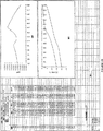
第1図は、本発明で使用する典型的なガス混合物に関する、エンタルピー対温度のグラフである。
第2図は、小型冷凍システムの一次部分の一態様の、斜視図である。
第3図は、第2図に示した冷凍システムの、冷凍外科用プローブ部分の遠位端部を示す部分断面図である。
第4図は、第3図に示した冷凍外科用プローブで使用した、超小型熱交換器で使用する、熱交換器プレートの一構成の好ましい態様を示す正面図である。
第5図は、孔の、第4図に示された配向とは異なる角度配向を示す、熱交換器の第二の構成の正面図である。
第6図は、第3図に示したプローブで使用した、超小型熱交換器で使用する、スペーサの好ましい一態様を示す正面図である。
第7図は、該超小型熱交換器の第二の態様で使用するスペーサの第二の態様を示す正面図である。
第8図は、該超小型熱交換器の第二の態様で使用するプレートの第一の構成を示す正面図である。
第9図は、該超小型熱交換器の第二の態様で使用するプレートの第二の構成を示す正面図であり、高圧および低圧部材の異なる配向を示す。
第10図は、供給および戻りガス混合物の流れを示す、該超小型熱交換器の第二の態様で使用するプレートおよびスペーサの、一連の正面図である。
第11図は、供給および戻りガス混合物の流れを示す、第10図に示された、複数のプレートおよびスペーサの断面図である。
第12図は、最終的な成形を施す前の、該超小型熱交換器の第三の態様を示す斜視図である。
第13図は、最終的な成形後の、第12図に示された熱交換器の斜視図である。
第14図は、冷凍プローブの遠位端部の第二の態様の部分断面図であり、細長い熱伝達エレメントを示す図である。
第15図は、第14図のライン15-15に沿ってとった、該第二の態様の断面図である。
第16〜32図は、例示の目的で与えられた、17種の流体混合物に関するエンタルピー表およびグラフである。
第33図は、本発明の一次および二次閉ループを模式的に示す図である。
第34図は、低温プローブのハンドル内に配列できるような、本発明の該一次閉ループおよび該二次閉ループ部分の断面図である。
第35図は、本発明によるハンドヘルド低温プローブの断面図である。
第36図は、該低温プローブのハンドル内に配置された、小型一次熱交換器で使用する、同軸状二重内腔式チューブの横断面図である。
第37図は、該一次/二次熱交換器で使用する、該コイル式多重内腔型チューブの横断面図である。
発明の詳細な説明
本発明は、該一次ガス混合物が該一次ジュールトムソン膨張エレメントを通過する前に、該一次高圧ガス混合物を予備冷却するための、二次閉ループジュールトムソン冷凍システムの適当な利用に関する。これは、該冷凍外科用のプローブの先端部における、利用可能な冷却能力を最大にするためのものである。
該一次流体混合物を、該低温チップ内の超小型熱交換器に供給する前に、該流体混合物を予備冷却することが本発明の目的である。この予備冷却は、公知の比較的大きな熱交換器を使用して、該一次流体混合物を、該カテーテルに導入する前に、行うことができる。しかしながら、取扱いの容易さおよび最大の効率を達成するためには、本発明は、低温プローブのハンドル内等の、該処理領域近傍を予備冷却する設備に着目する。これは、予備冷却された流体混合物の流れ経路の長さを最小化することが、該予備冷却システムの効率を最大にするからである。
冷凍外科用デバイスの設計における重要な一パラメータは、該冷凍システムが達成できる冷却能力である。この冷却能力は、度/秒で表した冷却速度、および該組織の冷凍中に、該プローブ先端部で維持できる温度を決定付ける。該冷凍速度は細胞を死滅するのに重要である。というのは、より迅速な冷凍が、より良好な細胞内氷結晶の生成をもたらし、細胞溶解をもたらすからである。該冷凍速度は、また患者に対する所定の手順の実施に必要な時間の長さをも決定する。この手順が迅速である程、該手順の該患者に対する有害性は低くなる。
該プローブの低温チップにおいて維持できる温度が、周辺組織内に形成される該氷球のサイズを決定する。これは、勿論各位置における破壊組織の全体積、および該手順を完了できる速度を決定する。例えば、所定のガス混合物を使用した第一の低温プローブが、30ワットなる冷却能をもつ場合、低温チップの温度を-100℃に維持できると仮定すると、テストゲル中には、15分以内に、径4.5cmまでの氷球が生成される。該迅速な温度降下のために、同様なサイズの生組織内で、かなりの割合の細胞の死が生ずるであろう。これに対して、同一のガス混合物を使用する、僅かに10ワットの冷却能をもつ、第二の低温プローブを考察する。この第二の低温プローブは、僅かに-50℃の温度を維持できるに過ぎず、これは15分以内に、径2.5cm程度の氷球を形成するに過ぎない。従って、上記の高率の細胞死は、径4.5cmの球ではなく、径2.5cmの生組織球内でのみ起こる。その上、所定の該氷球のサイズが、僅かに2.5cmである場合には、該第一の低温プローブは、15分ではなく、5分以内にこのような氷球の生成を達成できる。従って、いずれかの標準により、該第一の低温プローブは、該低出力の第二の低温プローブと比較して、より良好な結果を、より迅速に達成するであろう。
ジュールトムソン冷凍外科デバイスにおいては、高圧流体は、ある種の制限手段、例えば小さなオリフィスまたはクリンプ加工したチューブ等を横切って膨張する。圧力における突然の降下は、温度における対応する降下をもたらす。このデバイスの冷却能力は、該冷凍剤の質量流量と、異なる圧力および温度における該エンタルピー差との積である。該流量は、オリフィスのサイズおよび該冷凍剤の温度および圧力の関数である。非閉塞条件下での、与えられたオリフィスのサイズに関連して、該冷凍剤の密度はより高い圧力およびより低い温度において高く、より高い質量流量を与える。最大流量は、該冷凍剤が液体である点において見られる。該エンタルピー差は,また該圧力および温度の関数であり、2つの状態間の該エンタルピー差は、より高い圧力およびより低い温度においてより高くなる。与えられた温度および与えられた圧力に対して、2つの状態間の最大のエンタルピー差は、該冷凍剤の液化点で生じる。1またはそれ以上の予備冷却用の熱交換器を、該冷凍システムの該膨張エレメント近傍に組み込んで、温かい高圧の該冷凍剤の冷却または液化を促進し、結果として該システムの出力を高めることができる。
亜酸化窒素は、ジュールトムソン冷凍外科用システムにおいて、最も一般的に使用される冷凍剤である。該システムの高圧が約4.5MPaである場合、亜酸化窒素は、熱交換器の助けなしに、膨張時に液化し、また最大の冷却能力を達成する。しかしながら、亜酸化窒素は、かかる高い圧力下で作動させる必要があり、しかも達成できる最低温度は-50〜-70℃の範囲であり、これは幾つかの冷凍外科用途に対しては比較的高い温度である。従って、亜酸化窒素システムの安全性および効率は、幾つかの用途、例えば心臓組織の分離、および子宮内膜の分離等に対しては、望ましいレベル以下である。
本特許出願で論じる該流体混合物および冷凍剤は、低圧で作動し、またより低い温度を達成するので、これらはより安全かつより効率的である。例えば、66%のクリプトン、14%のR142b、10%のR22および10%のR23を含む混合物は2.1MPaなる圧力から、-120℃なる温度を達成できる。0.6g/secなる流量において、約30ワットの冷却能力を達成する。しかしながら、この混合物は液化せず、また熱交換器の助けなしにその最大の冷却能力に達する。
この型の混合物を使用した場合には、ある問題を生ずる。該混合物は、該冷凍システムを始動する際に、温かいガス状態にあるので、その初期流量は極めて低く、またその出力も非常に低い。使用した熱交換器が、それ程高い効率をもたない場合、その初期の冷却は該低流量を克服するために、極めて遅い。更に、該低温チップは、典型的には冷却を開始する前に患者内に、ターゲット組織と接した状態で配置され、従ってかなりの熱負荷が該チップに及ぼされる。このことは、冷却が不当に遅く、また幾つかの場合には冷却が全く生じない可能性があることを意味する。
起こり得るもう一つの問題は、混在物による該膨張エレメントの閉塞である。水および油が存在する場合、これらは該冷凍剤の温度の降下に伴って、液化し、かつ凍結するであろう。該オリフィスまたは他の膨張エレメントのサイズは小さいが故に、これは容易に閉塞を生ずる恐れがある。より大きな極低温システムにおいては、調節可能なオリフィスを使用して、この閉塞の問題を解消することができる。しかしながら、この小さな医療システムでは、調節可能なオリフィスは大き過ぎ、非実用的である。
幾つかの混合ガスジュールトムソンシステムにおいては、僅かな予備冷却が、しばしば冷却能力の大幅な増加をもたらす。流体混合物の選択および予備冷却の利用は、従って整合性をもつ必要がある。
混合ガス冷凍外科システムの性能を最大にし、かつ緩慢な冷却速度および低い冷却能力に関連する問題点を解消するために、独立した閉ループジュールトムソン二次冷凍システムを、本発明に組み込む。この二次システムは、R13b1等の単一の冷媒を使用して、該一次ガス混合物を該低温チップに流す前に、該低温プローブのハンドル内の該一次ガス混合物を予備冷却する。この二次システムは、できる限り該低温チップに近接して配置された、一次/二次熱交換器によりこの予備冷却を達成して、該冷却された一次ガス混合物が該低温チップに至る前に、該ガス混合物の過度の加温を防止する。
この予備冷却は、該システムの該初期流量および冷却能力をより高い値とし、結果として該初期冷却速度を一層高くする。最適の流体混合物の選択は、該予備冷却をより効果的なものとし、該冷却能力を最大にする。幾つかの混合物を使用し、かつ予備冷却を利用することにより、該一次膨張エレメントに近接する該低温チップにおける、熱交換器の使用を不要とすることができる。更なる利点は、該予備冷却が低温フィルタとして機能して、油および水等の混在物を除去できることである。該混在物を除去しないと、該システムが冷却されるにつれて、該膨張エレメントを閉塞する可能性がある。このためには、該膨張エレメントよりも小さな開口をもつフィルタを組み込むこともできるが、全開口面積がより大きくなり、大幅な圧力降下の達成を妨害する恐れがある。
本発明の最適化のためにも、最適な流体混合物の選択が必要となる。というのは、所定の温度において必要な冷却能力を達成できる公知の単一のガスは存在せず、選択された用途で使用するためのシステムには、所定のサイズに係わる制限および圧力の制限が課せられる。幾つかのガス混合物が、本発明で使用するために確認され、またその他のものも同様に確認されるであろうことが予想される。適当なガス混合物は、種々の形状をとることができ、またこれらは炭化水素を主成分とするあるいは非−炭化水素を主成分とするものの何れてあってもよい。幾つかの流体混合物は、その他のものよりも著しく良好に機能し、従って一群の利用可能な混合物から、最適の混合物を同定し、かつ選択することが重要である。多くの用途に対して有用であるものと一般的に確認されている一種の混合物は、30%のメタン、23%の窒素、23%のイソブタン、19%のエタンおよび5%のプロパンである。このようなガス混合物の等エンタルピー的膨張を可能とする温度を、第1図に示す。第1図は1バール(14.5psia)、21バール(305psia)および41バール(595psia)の圧力におけるこのガス混合物のエンタルピー曲線である。高圧から低圧への等エンタルピー性膨張は、該グラフを横切って、左に向かって水平に進み、温度降下を伴う。利用可能な最低温度は、曲線が交叉する、100K以下の何れかの点にあるはずである。該高圧ガス混合物の温度が低い程、このジュールトムソン膨張エレメントによる該等エンタルピー性膨張により達成できる温度は低くなる。該グラフからはまた、41バールからの膨張および21バールからの膨張により達成される温度間には、殆ど差がないことも理解できる。例えば、使用する熱交換器が、該高圧ガス混合物を、該膨張エレメントの直上流にて、210Kの温度まで冷却できるものと仮定する。21バールという高い圧力を使用した場合、該等エンタルピー性膨張は、180Kなる温度を与えるであろう。該ガス混合物が、逆に41バールに加圧された場合には、等エンタルピー的膨張後に達成される温度は、依然として僅かに173Kであるに過ぎない。更に、所定の温度における該高圧曲線と該1バール曲線との間の差異により表される、該冷却能力、即ち出力は、該高圧が21バールであるか、41バールであるかによらず同様である。従って、初期圧を21バール、即ち約300psiaに下げることにより達成される付随的な安全性は、ほんの僅かな性能の損失をもたらすに過ぎない。明らかに、与えられたガス混合物に対して、該熱交換器の効率が高い程、最終的に達成できる該プローブ温度は低くなり、かつ該冷却能力も大きくなるであろう。
第2図は、冷凍外科用途用の、本発明の冷凍システム10の該一次ループ部分を示す図である。該システム10の該一次部分は、市販品として入手できる一段圧縮機12、該圧縮機12の入口および出口に接続された、可撓性の二重内腔式ホース14、ステアリングハンドル16および冷凍外科用プローブ18からなっている。該圧縮機12は、しばしば後部冷却機、油分離機および吸着フィルタを使用する、利用可能な数種の圧縮機の何れであってもよい。あるいは、油を含まない圧縮機も使用可能である。該ホース14は、使用するガス混合物に関連して、関与する該圧力および化学的暴露にとって適した、任意の可撓性の二重内腔式ホースであり得る。該ハンドル16は、医師が該ガス混合物の流量を絞るのに使用できるように設けられた、制御膨張エレメントをもつことができる。また、該ガスの流れは、該圧縮機における流動を調節するフットスイッチを介して該流れを制御することも可能である。該プローブ18は、該圧縮機12の該出口からの該高圧ガス混合物を導き、かつ該膨張した低圧ガスを、該圧縮機12の入口に戻すための内側チューブを備えた同軸状カテーテルである。このプローブ18は、遠位端部即ち領域20を有し、該領域内には、該熱交換器、膨張エレメントおよび熱伝達エレメントが配置されている。該プローブ18は、冷却すべき物体に、例えば患者の血管系を通してその心臓内に挿入するのに適当な径、長さおよび柔軟性をもつものである。
第3図は、該同軸状カテーテル18の該遠位端部20の部分断面図である。このカテーテル18は、外側チューブ22と内側チューブ24とからなる。該外側チューブ22は、該カテーテル18の端部に対して連続であり、あるいは延長部23をもつことができ、該延長部は全ての実際上の目的に対して、該外側チューブ22の一体化部分と考えるべきである。該外側チューブ22は、公知の方法に従って、ワイヤー編組ポリマー、例えばボリアミド−エーテルコポリマーから作成される。該内側チューブ24は、特定の用途に関連した該最大の高圧に対して十分な耐圧性を有する、ワイヤー編組ポリイミドから作成される。この内側チューブ24は、入口継手26によって、超小型熱交換器28の近位端部と接続されている。該熱交換器28の遠位端部には、一次ジュールトムソン膨張エレメント30が取り付けられている。この一次膨張エレメント30の該遠位端部は、該外側チューブ22あるいは延長部23の遠位端部において、空洞31に暴露されており、熱伝達エレメント32により閉じられている。該膨張したガス混合物は、該熱伝達エレメント32の内部表面66を冷却し、結果としてその外部表面68を冷却する。この外部表面68は、医師により、冷却すべき該物体と接触して配置される。
より具体的には、該内側高圧チューブ24の該遠位端部は、該入口継手26によって、該熱交換器28の該近位端部において、該高圧入口34と接続されている。この高圧入口34は、本態様では該熱交換器28の中心軸部分として示されている、該熱交換器を通して、高圧供給流路36に導かれる。この熱交換器28は、また該空洞31に暴露された該遠位端部において、低圧入口38をも有する。この低圧入口38は、該高圧流路36を包囲する、該熱交換器の該外側環状部分として図示されている、低圧戻り流路40に導かれる。該低圧流路を流動する、該低圧かつ低温のガス混合物は、該高圧流路を流動する、該高圧かつ高温のガス混合物を予備冷却する。該熱交換器28は、交互に重ねられた銅板42とステンレススチールスペーサ44とで構成され、これらは一緒に拡散結合されている。他の付着法も利用可能である。この熱交換器28は、本図では、簡単化のためにプレート42およびスペーサ44上に外部スキンをもつように図示されているが、実際には該スキンは最適には外部リング45により与えられ、これは、各スペーサ44上で、以下においてより明確になるように、各プレート42の最外部の環状部分に結合されている。各プレート42の該中央部分は複数の貫通孔46を有し、該貫通孔は、該スペーサ44内の中心開口と共に、長手方向に該熱交換器28を介して、その該遠位方向に延びている、該高圧流路36を確立する。同様に、各プレート42の外部部分は、複数の貫通孔48を有し、これらは該スペーサ44の外部開口と共に、長手方向に該熱交換器28を介して、その該近位方向に延びる該低圧流路40を設定する。この高圧流路36は、各スペーサ44上の内部リング47により、該低圧流路40とは分離されている。
該熱交換器28を通る高圧ガス混合物は、該熱交換器の該中央遠位部分における高圧出口部50にて、該高圧流路を出、該一次ジュールトムソン等エンタルピー膨張エレメント30の入口52に入る。この一次膨張エレメント30は、第一の径をもつ第一段54を有し、ここで第二の大径までの等エンタルピー膨張が起こり、該ガス混合物の温度を、設計温度まで低下する。次いで、該ガス混合物は、該第二段56を通り、そこで該ガス混合物を該所定の温度に維持したままで、等温膨張が起こるが、この工程中に周辺構造体から熱を吸収する。該第一段54は金属シリンダー58を、選択されたサイズの金属ビーズにより、選択された充填密度にて満たすことにより作成され、該ガスの所定の膨張率を達成する。該ビーズは、該シリンダー58内の所定の位置で焼結される。同様に、該第二段56は、第二の金属シリンダー60を、選択されたサイズの金属ビーズにより、選択された充填密度にて満たすことにより作成され、該ガスの所定の膨張率を達成する。典型的には、この第二段56における該ビーズは、より大きな表面積を有していて、熱伝達性を高めるであろう。
該遠位方向に、該熱交換器28を流動する、該膨張した一次ガス混合物は、該熱交換器28の該近位端部における低圧出口62にて、該環状の低圧流路40を出る。この膨張したガス混合物は、該内側チューブ24を包囲する、該外側チューブ22の該内側内腔64に入り、該一次圧縮機12に戻される。
第4および5図は、該プレート42の構造および該熱交換器28内でのその環状の配向を、より明確に示している。各プレート42は、その中央部分を通る第一の複数の高圧孔46およびその外部環状部分を通る第二の複数の低圧孔48を有する。典型的には、該内側孔46の径および間隔は、該外側孔48の径および間隔よりも小さい。これら2種の異なる流路の孔の径および間隔の選択は、2つの異なる圧力における、最小圧力降下および最大熱伝達率を最適化するために、周知の設計原理に従って設計される。第4および5図は、また隣接プレート42間の相対的な環状配向をも示している。これら2つの図は、第5図のプレート42が、第4図のプレート42について回転すると、実際に同一のプレート構成を図示していることが理解できる。該プレート42で使用する該孔のパターンは変更することができ、その目的は、該ガス混合物と該プレート42との間の熱交換接触を最大にすることにある。ガスは、該プレートの該高圧部分から、低圧部分には流れず、第3図に示すように、該プレート42と間に挿入されたスペーサ44の内側リング47との間の接触により阻止される。隣接プレート42間の相対的な角度配向も、選択された孔のパターンに応じて変えることができ、その目的は該ガス混合物の乱流の形成を最大にして、熱伝達を促進することにある。第3、4および5図から、該流路36、40の何れかにおける該熱交換器28を流動するガスが、幾分湾曲した経路を流動し、該流れ経路の実質的な部分は、該熱交換器28の軸を横切る運動に関与することを明確に理解することができる。図示した態様においては、該流れの横方向の成分が、隣接プレート42間の相対的な角度配向のために生ずる。この湾曲した経路は、効率的な熱伝達を促進し、該超小型熱交換器28が、該ジュールトムソン流動制限膨張エレメント30による所定の等エンタルピー性膨張を可能とするのに必要な温度降下の達成を可能とし、最終的に該所定の冷却温度を達成する。本態様における熱流動は、実質的に動径方向をとる傾向がある。
第6図は該スペーサ44の好ましい態様を示し、該スペーサは該プレート42間に散在している。該スペーサ44は、所定の同心関係でスポーク70により支持されている、外部リング45および内部リング47を有する。該内部リング47内の内側開口72は、プレート42間の該高圧流路36の一部として機能する。該内部リング47と該外部リング45との間の複数の外部開口74は、プレート42間の該低圧流路40の一部として機能する。該内部リング47は、該高圧および低圧開口72、74間の仕切りとして作用する。
第7図は、該スペーサ44’の第二の態様を示し、これは第8および9図に示すような、プレート42’の第二の態様と共に使用できる。このスペーサ44’は外部リング45’および高/低圧仕切り47’を有する。この仕切り47’は、該高圧開口72’と該低圧開口74’とを分離している。このスペーサ44’を、第7図に示された配向から回転させて、以下において明らかにする理由から、該仕切り47’の配向を反転できることが理解される。第8図は、比較的小さな矩形の高圧孔46’および比較的大きな矩形の低圧孔48’を有するプレート42’を示し、該矩形孔46’および48’の長い辺は、垂直に配列されている。第9図は、同一の型のプレート42’を示し、該矩形孔46’、48’は水平に配列されている。該スペーサ44’と共にとることのできる、これら2つの孔パターンおよび該2つのスペーサ配向は、第10図に示すような、一連の隣接するプレート42’およびスペーサ44’を形成するように使用される。
第10図は、左から右へのこの一連の配列を示し、これらは順次該熱交換器の近位端部から該低圧側に向かって配列される。該矢印HPは、紙面内での該高圧ガス混合物の流れ経路を示し、一方で該矢印LPは、紙面外からの該低圧ガス混合物の経路を示す。第11図は、該積層されたプレート42’およびスペーサ44’を通る垂直断面を示すことにより、この流れ経路を更に説明するものである。鎖線は、隠れた高圧および低圧孔の位置を示すために使用した。ここでも、該ガス混合物が、該高圧および低圧流路36、40両者を通る湾曲した経路を流動することを理解できるが、この態様においては、該流れの横方向の成分は該第一の態様よりもより一層顕著であり、該熱の流れは動径方向ではなく寧ろ軸方向をとる傾向がある。
第12および13図は、積層されたプレートおよびスペーサではなく寧ろ巻回されたシートで構成された、該超小型熱交換器の更に別の態様を示す図である。該カテーテル18の該内側チューブ24は、第一シート76内にエッチングにより形成された迷路状の高圧流路36’と接続された状態で示されている。絞り部も、該高圧流路36’の出口にエッチングにより形成されており、ジュールトムソン膨張エレメント30’を生成する。第二シート80は、入口38’および出口62’と共に、そこにエッチングにより形成された低圧流路40’を有する。該第一シート76と該第二シート80との間には、スペーサシート78が配置されて、該高圧および低圧流路36’と40’とを分離している。これらシート76、78および80は、図示された配向で積層し、かつ一緒に拡散結合し、あるいはある他の適当な方法で接合することができる。次いで、このアセンブリーを第13図のように巻取り、シリンダー状の熱交換器28’を製造する。
第14および15図は、細長い熱伝達エレメント32’を有する、該カテーテル18’の遠位端部部分の第二の態様を示す図である。この態様は、該カテーテルの該端部部分が、該膨張エレメント30に取り付けられた流体チューブ27、流体チャンバー29および該流体チャンバー29と該膨張チューブ23との間の断熱体25をもつことができる。この構成は、該冷却出力が、主として該熱伝達エレメント32’を介して適用されることを保証している。
該熱交換器のサイズおよび固有の熱伝達容量は、使用した設計とは無関係に制限される。この装置を使用するためにもくろまれた微小環境において、空間は非常に重要である。従って、心臓カテーテルまたは印刷回路基板何れで使用されるかとは無関係に、厳密なサイズ上の制限が、該熱交換器に課せられる。例えば、心臓カテーテルは、冷却のために、該ターゲット領域まで、血管を介して導入しかつ操縦する必要がある。従って、当然心臓カテーテルは、これを通すための血管の径により、その径は厳密に制限される。更に、該カテーテルは、医師の制御下で該血管系に通すことができるように、高い操縦性をもつ必要がある。これらの操縦性に係わる要件は、該カテーテルに対して、該低温チップ熱交換器が配置されるその先端部近傍で、幾分かの柔軟性を要求する。不幸にも、該低温チップ熱交換器の殆どの設計は、剛性ではないとしても幾分か高い可能性がある。従って、該熱交換器の長さは、該領域における該カテーテルに幾分かの可撓性を残すために、厳密に制限される。勿論、該熱交換器のサイズの制限は、該熱交換器内で変換される熱量に、同程度の制限を及ぼすであろう。この種の、該低温チップ熱交換器のサイズおよび容量に関する制限は、二次閉ループジュールトムソン冷凍システムの使用によって、該全体としての冷凍システムの性能が、可能な最大のレベルに維持されることを示唆する。適当な予備冷却を、最適のガスまたは流体混合物と組み合わせた場合には、該システムは、該サイズにおける制限にも拘らず、可能な最良の冷却を達成するであろう。該適当な流体混合物選択法と組み合わせた、この予備冷却システムの目的は、該予備冷却用熱交換器と、該ジュールトムソン膨張エレメントとの組み合わせの冷却能力を、最大の値にすることである。
任意の特定のガス混合物に関連して、また任意の選択された圧力範囲および温度範囲に関連して、理想的熱交換器においてさえ、伝達可能な熱量における理論的な限界がある。この限界は以下の式で与えられる。
Qhx=n[h(P,Th)-h(P,Tc)]min
ここで、nはモル流量であり、hはモルエンタルピーであり、Thは熱交換器の高温端部の温度であり、Tcは該熱交換器の低温端部の温度であり、Pは圧力であり、このQhxの値は、該高圧および低圧両者において計算される。該下付記号minは使用する該Qhxの値が、これら2つの圧力にて計算した値の小さいものであることを意味する。
同様に、この特定の流体混合物に関連して、および該特定の温度および圧力範囲に関連して、理想的なジュールトムソン膨張エレメントにおいてさえ、達成し得る冷却能力には理論上の限界がある。この限界は以下の式で与えられる。
Qr=n[h(PL,T)-h(Ph,T)]min
ここで、PLは該低圧であり、Phは該高圧であり、またTは温度であり、該Qrの値は、該選択された温度範囲の両端における該高温と低温との間の複数の選択された温度において計算される。該下付記号minは使用する該Qrの値が、該選択された複数の温度で算出された値の最低値であることを意味する。
該理論的な冷却能力対該理論的な熱伝達容量の比、即ちQr/Qhxは、該特定の圧力および温度に渡る、該特定の流体混合物に特徴的な性能比であると考えることができる。本発明は、一群の候補混合物から1種の流体混合物を選択する方法をも包含し、該流体混合物は、該候補群の任意の流体混合物の中で、最大の性能比をもつであろう。
まず、純成分流体のリストを作成し、これから該候補流体混合物を処方する。各成分流体は単元素で構成される流体であり得または該成分流体は、数種の元素を含む化合物であり得る。各成分流体は有機または無機の何れであってもよい。一つの要件は、該流体混合物が、該選択された温度範囲における最低温度以下の三重点を有し、該装置内での該流体混合物の凍結を防止できるものである必要があることにある。この要件は、該リスト内の各成分流体に、遭遇する最低温度以下の三重点を確実にもたせることにより、満たすことができる。また、幾つかの成分流体は、該処方された流体混合物各々が、該予想される温度範囲以下の三重点をもつ限り、予想される温度範囲内に三重点をもつことができる。第二の要件は、各流体混合物が正のジュールトムソン係数をもたなければならず、換言すれば該流体混合物中の圧力降下が、温度降下により達成される必要があることにある。これを保証するための一つの方法は、該リスト上の該成分流体各々に、正の係数を確実にもたせることである。また、幾つかの成分流体は、各流体混合物の該係数が正である限り、負の係数をもつことができる。
該リスト内の該成分流体各々に対して、該モルエンタルピーが、該選択された温度範囲および該選択された圧力範囲に渡る、複数のデータ点において既知である必要がある。ここで、これらの選択された範囲は、該流体混合物が該冷凍装置にポンプ輸送されるであろう温度並びに圧力範囲である。
次いで、該成分流体の複数の混合物を選択するが、各流体混合物は幾つかの成分流体を含み、かつ各成分流体は特定のモル分率で存在する。理論的には、任意の数の成分流体を、単一の流体混合物に含めることができる。勿論、実際上は、計算上の能力のために、任意の一つの流体混合物に含めるべき成分流体の可能な最大数には、幾つかの制限が課せられるであろう。同一の成分流体を含むが、該成分流体が異なるモル分率で存在する、2つの流体混合物は、2つの異なる成分流体であると考えられる。2種程度の候補流体混合物を、最も簡単な場合の比較の目的で選択する。しかしながら、考察中の成分流体から処方できる最大数までの、任意数の混合物を処方することができる。次に、該成分流体各々の既知の熱力学的な特性に基づいて、各処方された流体混合物各々のモルエンタルピーを、該選択された範囲の温度および該選択された範囲の圧力に渡る、複数のデータ点において計算する。
該選択された温度範囲および圧力範囲に渡る、複数のデータ点における、各流体混合物のモルエンタルピーを計算するための、公知の一つの方法は、混合物の特性のデータベース(Mixture Property Database:DDMIX)プログラムおよび炭化水素混合物の熱物理的諸特性(Thermophysical Properties of Hydrocarbon Mixtures:SUPERTRAPP)プログラムにおいて使用されているような、拡張対応状態(extended corresponding states)法であり、これらプログラムはいずれも、ナショナルインスティチュートオブスタンダーズ&テクノロジー(National Institute of Standards and Technology:NIST)から入手できる。該候補流体混合物のエンタルピー値および他の熱物理的特性は、これらプログラムの助けにより、飽和境界整合に基づき、適当な形状因子を使用して、見積もることができる。典型的には、基準流体を選択し、該基準流体のもつ特性との関連で、他の流体の該熱物理的特性を与える。該冷凍剤R134は、これらの計算に対する適当な基準流体として機能することが分かったが、他の流体も基準流体とし機能し得る。
選択された該成分流体は、該選択された温度範囲の低温限界以下に、三重点をもち、固体生成の可能性を排除する必要がある。成分流体に関するデータベースは、冷凍剤、アルカンおよびアルケンを包含する軽質炭化水素、およびクリプトン、アルゴンおよびネオンを包含する希ガスを含むことができる。各選択された候補流体混合物の相分離およびエンタルピー含量は、温度および圧力の関数として計算される。
次に、各候補流体混合物に対して、一連の計算を行う。該高圧側または該低圧側のいずれかにおける、該熱交換器による該圧力降下は、しばしば無視できるものと仮定することができる。また、適当な圧力降下が予想される場合には、出発圧力は、該熱交換器内の該圧力降下を考慮して、選択することができる。該選択された圧力範囲内の該低圧に対して、該選択された温度範囲内の該低温における該流体混合物のモルエンタルピーを、該範囲の該高い温度における該モルエンタルピーから差し引いて、これら2つの温度における該流体混合物の状態間の、低圧エンタルピー差を得る。同様にして、該選択された範囲の該高圧に対して、該低温におけるモルエンタルピーを、該高温におけるモルエンタルピーから差し引いて、これら2つの温度における該流体混合物の状態間の、高圧エンタルピー差を得る。これら2つのエンタルピー差の低い値が、該選択された温度範囲および圧力範囲に渡り、該選択された流体混合物を使用して動作させた、理想的向流式熱交換器で達成できる理論上のモルエンタルピーである。該選択された温度および圧力範囲に渡る、該選択された流体混合物を使用した、このような熱交換器の理論上の熱伝達容量は、該流体混合物のモル流量とこの理論上のモルエンタルピー差との積である。この理論上のモル熱伝達容量を、候補流体混合物各々について計算する。
次いで、該選択された温度範囲に渡り、一定の増加率にて、複数の温度を選択する。該温度増加の数および大きさは、変えることができる。しばしば満足な温度増加率は5°である。1例として、該選択された温度範囲が120K〜270Kである場合、かつ該増加の大きさを5°に設定した場合には、全体としての増加段階は30であり、また31個の選択された温度が存在する。各候補流体混合物に対して、該選択された圧力範囲の上限における、該流体混合物のモルエンタルピーを、該圧力範囲の下限におけるモルエンタルピーから差し引いて、これら2つの圧力における該流体混合物の状態間のモルエンタルピー差を得る。この計算を選択された該31個の温度各々において実施する。使用した選択温度数が多い程、かつ該増分の大きさが小さい程、該計算された情報の有用性は高いであろう。これら選択された温度各々において計算された該モルエンタルピー差は、理論的なエンタルピー増分であり、これは、温度を一定値に維持した場合には、該温度において、該高圧から該低圧まで、該候補流体混合物が膨張する際に生ずるはずである。
しかしながら、ジュールトムソン膨張では、該流体が該膨張エレメントを流動する際に、該流体からのまたは該流体への熱伝達の機会は殆どまたは全くなく、該流体のポテンシャルエネルギーの変動はなく、仕事も全くなされず、かつ該流体の運動エネルギーの変化も殆どまたは全くない。従って、該膨張前後の該流体のエンタルピー状態は、本質的に同一である。該膨張中に圧力は急激に減少するので、該流体の温度も急激に低下し、かくしてエンタルピーが本質的に一定に維持される。次いで、このより低温の流体を使用して、その周辺を冷却することができる。従って、実際には該温度は該膨張中に一定には維持されず、また該選択された温度範囲内で、該候補流体混合物のジュールトムソン膨張により利用できる理論上の冷却能力は、任意の該選択された温度における該最低の理論的なエンタルピー差の関数である。より具体的には、該候補流体混合物のジュールトムソン膨張により利用できる理論上の冷却能力は、該流体混合物のモル流量と、該選択された温度範囲に渡る、任意の温度において計算された、該最低の理論的なモルエンタルピー差との積である。この理論上の冷却能力を、各候補流体混合物について計算する。
従って、該群における各候補流体混合物は、該選択された温度および圧力範囲に渡り、理論的な冷却能力および理論的な熱伝達容量を示す。該理論的な冷却能力対理論的な熱伝達容量の比は、該温度および圧力範囲に渡る、該特定の流体混合物に特有の性能比と呼ぶことができる。本発明の装置の動作を最適化するために、最高の性能比を与えるであろう流体混合物を、該候補流体混合物から選択する。これが、該選択された温度および圧力範囲内で、該候補群中の、最適な流体混合物である。該理論的な冷却能力が該理論的な熱伝達容量と同程度に大きいことを意味する、該性能比が1またはそれ以上である場合には、該所定の温度および圧力範囲に渡る、可能な最大の冷却能力はジュールトムソン膨張のみによって達成でき、熱交換器は必要とされない。該群における該最大の性能比が、1未満であった場合には、少なくとも一つの熱交換器を使用する必要があろう。
第16〜32図は、該拡張対応状態法により誘導された、種々の流体混合物のエンタルピー値を掲載した表A〜Qを示す。該候補流体混合物を処方する際に使用する、該成分流体はAr、CH4、C2H4、C3H4、Kr、N2、NF3、1-ペンテン、イソブタン、イソペンタン、プロピレン、R14、R22、R23、R32、R124およびR142bであった。これら成分流体の種々の混合物が、小型混合ガス冷凍システムの作動において有用であり得ることを見出した。各表のエンタルピー値は、低Hと表示された欄における、1.0バールなる低圧および高Hと表示された欄における21.0バールなる高圧における値である。これらのエンタルピー値に基づいて、計算を行って各温度増加値におけるΔHの値を計算する。次いで、以下に記載する方法に従って、該選択された温度範囲に基づいて、ΔH*の値を、各温度増加値において計算する。エンタルピーおよび関連する値の該表に加えて、各図はΔH*対温度のグラフ、および低Hおよび高H対温度のグラフをも示す。表A〜Hは、150K〜300Kの範囲内のエンタルピー値およびΔH*の値を示し、ここで興味ある該選択された温度範囲は150K〜270Kである。表I〜Mは、120K〜270Kの範囲内のエンタルピー値およびΔH*の値を示し、ここで興味ある該選択された温度範囲は120K〜270Kである。表N〜Qは、100K〜280Kの範囲内のエンタルピー値およびΔH*の値を示し、ここで興味ある該選択された温度範囲は100K〜260Kである。
これらの表によりカバーされる温度範囲は、ある混合物に関するエンタルピー値を、任意の所定の温度範囲に渡り与えることができ、与えられた表における該ΔH*の値が、興味ある該選択された温度範囲に基づいて計算されることを、明らかにする目的で任意的に選択したものであった。流体混合物同志の比較は、同一の選択された温度範囲に基づいて計算されたΔH*値を含む表のみからとることができる。例えば、該表の全てが、150K〜270Kの範囲に渡るエンタルピー値を含む。しかしながら、表A〜Hのみが、選択された温度範囲150K〜270Kに基づいて、計算されたΔH*の値を比較するのに利用できる。というのは、その他の表におけるΔH*の値は、異なる選択された温度範囲に基づいて計算されたからである。
同様に、表I〜Qは全て、120K〜270Kの範囲に渡るエンタルピー値を示しているが、表I〜Mのみが、この選択された温度範囲に基づいて、ΔH*の計算された値を比較するのに利用できる。これは、表N〜QのΔH*の計算された値は、選択された温度範囲100K〜260Kに基づいて計算されたものであるからである。与えられた表に対して、該選択された温度範囲外にあるΔH*の掲載された値は、本発明の方法により計算され、表に示されたものであるが、該選択された温度範囲内で使用するための流体混合物の選択には関連しない。
以下の議論により、参考として引用したこれら表によりカバーされる、選択された温度範囲が特定されるであろう。全ての場合において、該温度増分は5Kである。Hはモルエンタルピーである。熱物理的特性の値は、R134aに対する値を基準とするものである。各表は5Kの増分における、1.0バールの低圧および21.0バールの高圧に対する、該候補流体混合物のモルエンタルピー値を掲載している。更に、該範囲に渡る各増加温度に対して、あるΔHが与えられ、このΔHは該温度での、該低圧および該高圧におけるエンタルピー値間の差である。
与えられた表の低圧に対しては、該選択された範囲内の低温における該エンタルピー値を、該選択された範囲内の該高温における該エンタルピー値から差し引いて、低圧エンタルピー差を得る。これが、該表の左下端部近傍に示されたy値である。同様な計算を、高圧に対して実施して、高圧エンタルピー差を得る。これが、左下端部近傍に示されたx値である。該低圧エンタルピー差および該高圧エンタルピー差の低い値が、この選択された温度範囲に渡り、利用できる理論的なエンタルピー差である。これが、左下端部近傍に示されたnh値である。ギブスのモル自由エネルギーも示してある。
各増加温度に対して、該ΔHの欄に示された値を、該理論的なエンタルピー差nhで割り、その結果をΔH*と表記した欄に示す。この理論的なエンタルピー差nhは、選択された温度範囲に基づいているので、ΔH*の該計算値も、その温度範囲に基づくものである。該選択された温度範囲内の最低のΔH*の値は、任意の与えられた表に対して、該理論的熱伝達容量で割った該理論的冷却能力と同一である。というのは、該モル流量は両者の項において同一であるからである。この値、即ちΔH* minは、該選択された温度範囲に渡る、該流体混合物に関する性能比である。
一例として、温度範囲120K〜270Kおよび圧力範囲1.0バール〜21.0バールを選択する。表I〜Mは、この選択された温度範囲に渡る、5種の流体混合物に対するΔH*値を含む。この選択された温度範囲に渡って、ΔH* minの最大値をもつ該流体混合物を表Jに与え、またこの流体混合物に関するこのΔH* minの値は0.2180である。このことは、選択された温度範囲120K〜270Kに基づいて、この選択された温度および圧力範囲に渡り計算されたΔH* minの値を示す、これら表に与えられた該流体混合物の中で、最適の流体混合物は43%のアルゴン、13%のクリプトン、11%のR14、2%のR22、14%のR23、4%のR124および13%のイソペンタンを含むものであることを意味する。表I〜Mにおいて、50%またはそれ以上のモル組成値は、可能な誤差+/-10%を有し、20%〜49%の値は可能な誤差+/-7.5%を有し、また20%以下の値は可能な誤差+/-5%を有する。
更なる例として、温度範囲150K〜270Kを選択する。表A〜Hは、この範囲に基づいて7種の流体混合物について計算されたΔH*値を含む。この範囲に渡り計算されたΔH*値を示す、これら表に与えられた該流体混合物に対して、ΔH* minの最大値をもつ流体混合物は表Eに与えられており、この流体混合物に関する該ΔH* minの値は0.3756である。このことは、この選択された温度および圧力範囲に渡り、これら表に与えられた該流体混合物の中で、最適の流体混合物は7%のR22、7%のR23、20%のR142b、55%のクリプトンおよび11%のNF3を含むものであることを意味する。表A〜Hにおいて、該モル組成値は可能な誤差+/-10%を有する。
これら表の利用法を、該選択されたガス混合物から毒性または炎症性をもつものを排除する手段を示すことにより、更に説明する。例えば、NF3が潜在的にヒトに対して有害であることに注意して、最後の例において使用した該流体混合物は、心臓カテーテルで使用されるであろう、混合ガス冷凍システムで使用するには望ましくない可能性がある。類似するが、この成分流体を含まない流体混合物を表Cに与える。同一の選択され温度範囲に渡る、該流体混合物に関する該ΔH* minの値は0.3580であることが理解できる。このことは、この選択された温度および圧力範囲に渡り、これらの表に与えられた該流体混合物の中で、最適な非−毒性の流体混合物は7.5%のR22、7.5%のR23、20%のR142bおよび65%のクリプトンを含むものであることを意味する。従って、毒性または炎症性は、選択されたガス混合物のほんの僅かな変更により排除することができる。
これら表に与えられた該一次流体混合物の幾つかについては、ΔH*の最小値は、該選択された温度範囲の上限部分で起こることを理解することができる。このような流体混合物に対して、該一次流体混合物の、二次冷凍システムによる予備冷却は、該温度範囲の上限を、該一次流体混合物が該一次膨張エレメントを流動する際に、より高いΔH* minの値もたらすレベルまで、低下し得る。
例えば、該流体混合物を該カテーテルに導入する前に、該流体混合物の温度を270Kから260Kに下げるために、予備冷却が利用可能であるかにつき考察する。表Bに与えられた該混合物は、40%を越えるΔH* minの比例的増加を示すであろう。これは、表Dに与えられた混合物により得られる、20%を越える比例的増加のほぼ2倍である。従って、該流体混合物を該超小型熱交換器に導入する前に、該混合物を予備冷却することが可能であり、かつこの予備冷却を利用して、該システムの性能を調節することが望ましいシステムにおいては、表Bの混合物がより有利であろう。
類似する沸点をもつガスが、選択された流体混合物内で互換性をもつことに注意すべきである。例えば、R124は、R142bまたはイソブタンと置換することができ、また窒素はアルゴンと置換できる。この置換は同等なまたは僅かに異なる割合で行うことができ、その際のΔH* minにおける変動は僅かである。上首尾のこの例は、表CおよびHを検討することにより理解できる。表Cの混合物は7.5%のR22、7.5%のR23、20%のR142bおよび65%のクリプトンを含み、これはΔH* minO.3580をもつ。表Hに与えた混合物では、R32がR22と置換され、またR124がR142bと置換されて、環境的に安全な混合物が与えられ、そのΔH* minは僅かに低下して、0.3491となるが、その降下は僅かに約2%である。
第33図は、該予備冷却の概念を組み込んだ、本発明の二重閉ループ冷凍システム10を模式的に示す図である。該一次ループ100は、幾つかの点で、該予備冷却されないシステムにおいて上記した該一次ループと類似している。該二次ループ200が、該予備冷却効果を最大にするために付加されている。該一次ループ100は、高圧経路110と低圧経路120とからなる。一次ループ用圧縮機130は、選択された圧力および温度、例えば420psiaおよび300Kまで、該一次ガス混合物を圧縮する。次いで、該高圧一次ガス混合物は、第一の一次熱交換器140を介して、該一次圧縮機130の出口132から流動する。該熱交換器は低温プローブのハンドルに配置される小型の熱交換器であり得る。具体的には、該高圧一次ガス混合物は、該第一の一次熱交換器140の該高圧流路142を通過し、そこで低温、例えば280Kまで冷却される。該所定の温度および冷却能力に応じて、幾つかの用途では該第一の一次熱交換器140を必要としない可能性がある。
次いで、この高圧ガス混合物は、一次/二次熱交換器240、具体的には該一次/二次熱交換器240の該高圧一次流路170を通過し、該混合物は更に低い温度、例えば220Kまで冷却される。次に、この高圧一次ガス混合物は、第二の一次熱交換器160、具体的には該高圧流路162を通り、そこで更に一層、例えば160Kまで冷却される。この第二の一次熱交換器は、上記の予備冷却しないシステムにおいて論じた、積層型の熱交換器に匹敵するものである。所定の温度および冷却能力に依存して、幾つかの用途では、この第二の一次熱交換器160は必要とされない可能性がある。
次に、このガス混合物は、該一次ジュールトムソン膨張エレメント150に流入する。この一次膨張エレメント150内で、例えば130Kなる温度まで、等エンタルピー的に膨張した後、この膨張した低圧ガス混合物はターゲット組織Tを冷却する。
次に、この低圧一次ガス混合物は、逆に該第二の一次熱交換器160内の低圧流路164を通り、該流路において該混合物は、220Kまで温められ、また該第一の一次熱交換器140における低圧流路144を通り、そこで300Kまで温められる。次いで、この低圧ガス混合物は、該一次圧縮機130の入口134に戻る。
該二次ループ200は高圧経路210と低圧経路220とからなる。二次ループ圧縮機230は、該第二の冷凍剤を、該一次システムに見られた圧よりも比較的高い可能性のある圧にまで圧縮する。というのは、該第二のシステムは、該プローブのカニューレには入らないからである。次に、この高圧の二次冷凍剤は、一次/二次熱交換器240を介して、該第二の圧縮機230の出口232から流出する。該熱交換器も該低温プローブのハンドル内に配置される小型熱交換器であり得る。具体的には、該高圧の二次冷凍剤は、該一次/二次熱交換器240の該二次高庄流路242を通り、そこでより低温まで冷却される。
次いで、該高圧二次冷凍剤を、二次ジュールトムソン膨張エレメント250に通す。この二次膨張エレメント250内で等エンタルピー的に膨張した後、膨張した該低圧二次冷凍剤は、該一次/二次熱交換器240内の低圧流路244を介して戻される。この低圧流路244は、該高圧一次流路170を該高圧二次流路242から断熱するように配置されている。これは、該高圧流路から該低圧流路への熱の流れを保証する。次に、該低圧二次冷凍剤は、該二次圧縮機230の入口234に戻る。
第34図は、低温プローブのハンドル内に配置される、該二重ループ冷凍システムの一部を示す。該一次ループ100は、同軸状の二重内腔チューブとして該ハンドルに入り、該高圧経路110は内側内腔内にあり、かつ該低圧経路120はその外側内腔内にある。該第一の一次熱交換器140も、同軸状のコイル式チューブとして構成され、その高圧流路142はその内側内腔内にあり、またその低圧流路144はその外側内腔内にある。この二重内腔同軸状チューブの詳細は、第36図に示されている。該高圧および低圧経路110、120の両者は、第一の分離T継手180を通る。この分離T継手180において、該高圧経路110が該低圧経路120から分離する。該第一のT継手180からの、該高圧経路110は、該一次/二次熱交換器240の該高圧一次流路170を通る。
該一次/二次熱交換器240は、第37図に示したように、コイル式の多重内腔型チューブとして形成される。該高圧および低圧経路210、220は、二重内腔同軸状チューブを通過する。該高圧二次経路210は該内側内腔、即ち高圧二次流路242を貫通し、また該低圧二次経路220は、該外側内腔、即ち低圧二次流路244を貫通する。該低圧二次流路244の外側には、該高圧一次流路142が溶接されている。該高圧一次流路142は、複数の内側内腔143をもつことができ、該高圧一次ガス混合物は、該内側内腔143の全ておよび該内側内腔143間のおよびその回りの間隙空間を介して流動する。この配列は、該溶接体および該低圧二次流路244への改善された熱伝達を促進する。
該一次/二次熱交換器240から出た後、該高圧一次経路110は、該低温プローブのカニューレに接続することができる、高圧一次コネクタ192を介して、該低温チップ内の該一次膨張エレメント150まで流動する。該膨張エレメント150内で膨張した後、該低圧ガス混合物は、低圧一次コネクタ194を介して該T継手180に戻る。このT継手180において該低圧一次流路144は、同軸関係で、該高圧一次流路142と再結合して、該一次圧縮機130に戻る。
該二次ループ200も、該二次圧縮機230から、同軸二重内腔チューブとして該低温プローブのハンドルに入り、該高圧経路210はその内側内腔内にあり、また該低圧経路220はその外側内腔内にある。該二次高圧および低圧経路210、220は、上記のように、該一次/二次熱交換器240を通り、かつ第二の分離T継手280と接続する。この第二のT継手280において、該高圧二次経路210は該低圧二次経路220から分岐し、該二次膨張エレメント250を通る。該二次膨張エレメント250内で膨張した後、該低圧二次冷凍剤は、該低圧二次経路220を通り、該第二のT継手280の該高圧二次経路210と再結合する。
第35図は、ハンドルHを有する、剛性の低温プローブP内に、如何にして本発明の装置を配置するかを示している。該一次および二次閉ループシステム100、200は、該ハンドルHの端部に入る。該一次ガス混合物は該第一の一次熱交換器140を通り、一方で該第一の一次熱交換器140は、該二次冷凍剤によりバイパスされる。該一次ガス混合物および該二次冷凍剤両者は、前に記載したように、該一次/二次熱交換器240を通過する。次いで、該二次冷凍剤は、該二次膨張エレメント250内で等エンタルピー的に膨張し、該一次/二次熱交換器240を介して戻る。次に、該二次冷凍剤は、該ハンドルHを出て、該二次圧縮機230に戻る。該一次ガス混合物は、該コネクタ192、194を通り、該低温チップCTに達する。該低温チップCTにおいて、該高圧一次ガス混合物は、該超小型一次熱交換器160を通り、次いで該一次膨張エレメント150を通過する。該超小型熱交換器160はコイル式高圧チューブとして図示されており、該低圧一次ガス混合物は、該コイルを介して戻る。膨張され、かつ冷却された該低圧一次ガス混合物は、該ハンドルHを出る前に、該超小型一次熱交換器160および該第一の一次熱交換器140を通り、該一次圧縮機130に戻る。
ここに呈示しかつ詳細に説明したような特定の発明は、以前に述べた本発明の目的を十分に満たすことができるが、この開示は、本発明の現時点で好ましい態様の単なる例示であり、また添付した請求の範囲以外によって何等制限されるものではないと、理解すべきである。Background of the Invention
The present invention relates to the field of cooling small objects or very small parts of objects to very low temperatures. The object to be cooled can include biological materials, electronic components, and the like.
In many different areas being tried, it may be desirable to be able to selectively cool even extremely small or even microscopic objects to extremely low temperatures without affecting the temperature of surrounding objects. There is. This is true in the field of electronics where it is desired to cool a small component on a circuit board without substantially cooling adjacent components. In the practice of cryosurgery, even in the medical field where it may be desirable to be able to cool discontinuous micro-parts of biological tissue to extremely low temperatures without substantially cooling the adjacent tissue of the organ of interest. Is true. For simplicity, this document aims to meet this need in the medical field, but it will be understood that use of the present invention in other fields, such as electronics, is within the scope of the present invention. Should.
Cryosurgery is becoming an important method in the fields of medicine, dentistry and veterinary medicine. Special results have already been experienced in the fields of gynecology and dermatology. Other disciplines such as neurosurgery and urology can also benefit from the practice of cryosurgery techniques, but have been found only in limited ways. Unfortunately, the commonly known cryosurgical instruments have some limitations that make their use difficult or impossible in some such areas. Specifically, known systems are not optimally designed to have sufficient accuracy and flexibility to allow their widespread use endoscopically and percutaneously.
In the practice of cryosurgery, typically a cryosurgical application system designed to properly freeze target tissue is used to destroy diseased or altered cells in the tissue. Yes. The abnormal cells to be destroyed are surrounded by healthy tissue that should often be kept intact. Thus, the particular probe or other applicator used in a given application is designed to have the optimal shape and size for that application to achieve this selective tissue cooling. When using a probe, the other parts of the refrigeration system need to be designed to provide sufficient cooling, and sufficient cooling techniques can cool the working part of the probe to a predetermined temperature, and It includes having sufficient power and capacity to maintain a given temperature for a given heat load. The entire system needs to be designed to place the working part of the probe at the location of the tissue to be frozen without any undesired effects on other organs or systems.
Commonly known cryosurgical systems typically use liquid nitrogen or nitrous oxide as the refrigerant fluid. Liquid nitrogen is usually sprayed or circulated over the tissue to be destroyed to cool the probe applied to the tissue. Liquid nitrogen has a very low temperature of about 77 K and a high cooling capacity, which makes it very desirable for this purpose. However, liquid nitrogen typically evaporates during use and escapes into the atmosphere, so the storage tank needs to be replaced periodically. Moreover, since the liquid is very cold, the probe and other equipment used for its application requires a vacuum jacket or other type of thermal insulation. This makes the probe relatively complex, bulky and rigid and therefore unsuitable for endoscopic or intravascular applications. The need for a relatively bulky supply hose and the gradual cooling of all associated elements make the liquid nitrogen equipment uncomfortable for the physician, and these cause undesired tissue damage there is a possibility.
Nitrous oxide systems typically achieve cooling by pressurizing the gas and then expanding it at the probe tip via a Joule-Thompson expansion element, such as a valve, orifice or other type of flow restricting means. ing. Such an arbitrary device is hereinafter simply referred to as a Joule Thompson “expansion element”. This typical nitrous oxide system pressurizes the gas to 700-800 psia to achieve a practical temperature on the order of about 190-210K. The nitrous oxide system cannot achieve values close to the temperature and power achieved by the liquid nitrogen system. The maximum temperature drop achievable with a nitrous oxide system is up to 184K, which is the boiling point of nitrous oxide. This nitrous oxide system has several advantages in that the introduced high pressure gas is essentially at room temperature until it reaches the Joule Thompson element at the probe tip. This eliminates the need for thermal insulation of the system and thus simplifies achieving miniaturization and flexibility to some extent. However, tissue destruction and other applications are limited due to the relatively warm temperature and low power. For many such applications, temperatures below 184K are desirable. Furthermore, the nitrous oxide typically needs to be released into the atmosphere after passing through the system. This is because available compressors suitable for achieving this required high pressure are not reliable and easily available commercially.
In many Joule-Thompson systems, a single non-ideal gas is pressurized and then expanded through a throttle component or expansion element to achieve isenthalpy cooling. The characteristics of the gas used, such as boiling point, inversion temperature, critical temperature and critical pressure, determine the starting pressure required to reach a predetermined cooling temperature. The Joule-Thompson system typically uses a heat exchanger to cool the incoming high pressure gas with the expanded effluent gas, achieving a higher temperature drop and greater cooling capacity during expansion . For a given Joule Thompson system, the predetermined cooling is indicative of the predetermined heat exchange capacity. Finned tube heat exchangers are used, but these are necessarily bulky to achieve the desired cooling and prevent its use in micro systems such as instruments delivered to a location by a catheter. It is. Smaller heat exchangers are also known and consist of a photo-etched glass plate. The size of these heat exchange systems is still in the range of a few centimeters square and is still bulky for use in truly micro devices such as endoscopes, catheters and other systems. Moreover, these heat exchangers are flat and difficult to incorporate into an annular structure such as a catheter or endoscope. In many of these medical applications, the dimensions of the component are less than about 3 mm wide to allow for incorporation into a catheter or endoscope, and preferably less than 15 mm in length to provide sufficient flexibility. It is necessary to allow sex.
The requirements for the heat exchanger can be somewhat relaxed by pre-cooling the gas before sending it to the heat exchanger at the probe tip. This can be achieved by incorporating a Peltier device in the flow path of the probe tip in front of the heat exchanger. On the cold side surface of the Peltier device, the gas flowing through the heat exchanger is cooled before reaching the heat exchanger at the probe tip. Alternatively, the incoming high pressure stream diverts a portion of the flow and expands it so that it can cool the remaining portion of the introduced flow before reaching the heat exchanger at the probe tip. It is also possible to branch.
A significant improvement in the cooling capacity of the Joule Thompson system can be realized by using a gas mixture rather than a single gas. For example, the addition of hydrocarbons to nitrogen makes it possible to increase the temperature drop and cooling capacity for a given inlet pressure. It is also possible to reduce the pressure and achieve performance comparable to a single gas system at high pressure. Like single gas systems, these mixed gas systems have requirements for heat exchangers and are limited in their miniaturization potential due to the size of the heat exchangers. The improved cooling performance achieved by the mixed gas system is highly desirable for medical and other micro systems.
Several mixed gas systems have been devised, where high pressure is not a major concern, and bulky and high efficiency heat exchangers can be used, but these are typically used in defense and space applications. Used in. The glass plate heat exchangers described above are used in some such systems, and these systems often require a pressure of 1200 psia. In many applications, such as laser systems, superconductivity, electronics and cryosurgery, the use of pressures above about 420 psia is safe and costly and reliable due to the short lifetime of the device. Undesirable for low reason. Furthermore, endoscopic or percutaneous applications make it impossible to use any heat exchanger having a width greater than about 3 mm or a length greater than about 15 mm.
Specifically, it is desirable to develop long, thin, flexible cryogenic probes such as transvascular heart catheters. The cardiac catheter must be very thin, less than 5 mm, and must be very flexible and can be inserted from the access point in the remote vessel to the heart. Cryosurgical catheters used in such applications also need to have a relatively low operating pressure for safety reasons. It must be capable of cooling to overcome the ambient heat load provided by circulating blood, and must be able to achieve a sufficiently low temperature to destroy the target tissue. Finally, the low temperature heat transfer element needs to be limited to only the distal or distal region of the catheter to prevent damage to tissues other than the target tissue.
One of the objects of the present invention is a method for precooling a primary loop fluid mixture with a secondary loop Joule-Thomson cooling cycle and then using the primary loop fluid mixture in a small mixed gas cooling system, and The object of the present invention is to provide an apparatus, wherein the cooling system is capable of achieving a cooling temperature of 183K or less by means of components that can be mounted in a manually supported cryoprobe using high pressures not exceeding 420 psia. It is. It is a further object of the present invention to provide a sufficiently low temperature for precooling the primary loop fluid mixture and then isothermally expanding the fluid mixture through a Joule-Thompson expansion element using a small refrigeration system. Obtain a high pressure gas mixture, achieve an expansion gas temperature as low as at least 183K, with sufficient cooling capacity to maintain this temperature when a heat load is applied, and at a high inlet pressure not exceeding 420 psia It is an object of the present invention to provide the precooling method and apparatus.
Brief summary of the invention
The present invention includes a method and apparatus for operating a small refrigeration system, which selects an optimal fluid mixture for use as the primary refrigerant, and then uses the primary fluid mixture in a secondary closed-loop Joule-Thomson refrigeration cycle. Including pre-cooling and maximizing the available cooling capacity of the fluid mixture.
The cooling capacity is an important design parameter for cryosurgical instruments. Using a higher cooling capacity results in a quicker temperature drop and a lower temperature can be maintained at the probe tip during freezing. This ultimately achieves higher tissue destruction. The output of the mixed gas J-T cryosurgical device is a function of the enthalpy difference of the gas mixture and the mass flow rate. Precooling a gas mixture will increase the enthalpy difference available for cooling power. Furthermore, precooling will increase the average mass flow rate by making the gas denser.
Pre-cooling has two other important consequences. First, precooling reduces the size of the heat exchanger used with the probe. In a microenvironment envisioning the use of this device, severe size limitations will be imposed on the heat exchanger used, particularly the heat exchanger in the low temperature chip. For example, the diameter of a cardiac catheter is greatly limited by the diameter of the blood vessel through which the catheter is necessarily passed. Furthermore, maneuverability requirements require that the catheter be somewhat flexible and that the cryogenic tip heat exchanger be somewhat stiff, if not rigid. Thus, the allowable length of the low temperature chip heat exchanger is severely limited. Of course, the restrictions on the size of the low temperature chip heat exchanger limit the amount of heat that can be transferred in the heat exchanger. The present invention utilizes a particularly advantageous precooling. Secondly, the mixed gas J-T cryosurgical device requires an expansion element of a certain size, which may be partially or completely occluded by a mixture such as water or oil. This limits the flow rate and reduces cooling capacity. Pre-cooling allows these inclusions to be cryofiltered and removed from the circulating fluid before reaching the expansion element.
Although the term “gas mixture” will be used to some extent in this patent application, many compositions commonly referred to as gases actually have some liquid content at certain temperatures and pressures. It should be understood that this term is not limited to mixtures that do not include liquid components due to the well-known fact of having. The primary closed loop refrigeration system has a primary loop compressor for compressing the primary gas mixture to a pressure of up to 420 psia. The method and apparatus of the present invention can be used equally well in rigid hand-held cryogenic probes or catheters.
The high pressure primary gas mixture from the primary compressor is supplied to a high pressure supply tube, such as the inner tube of a coaxial double lumen tube that is led to the handle of a cryogenic probe. This dual lumen tube in turn feeds the high pressure gas mixture to the inlet at the adjacent end of the small counter-current primary heat exchanger in the handle. The high pressure primary gas mixture passes through a high pressure supply channel in the primary heat exchanger and is discharged from an outlet at the distal end of the primary heat exchanger. The high pressure flow path of the primary heat exchanger is connected to the inlet of the primary high pressure flow path in the primary-secondary heat exchanger, which is also provided in the handle of the cryogenic probe. The high pressure primary gas mixture passes through a high pressure flow path in the primary-secondary heat exchanger and is discharged from a distal outlet of the primary-secondary heat exchanger.
The primary-secondary heat exchanger is part of the secondary closed-loop Joule-Thomson refrigeration system, which in addition to the primary / secondary heat exchanger has a secondary compressor, and a secondary Joule-Thomson expansion element . The secondary compressor compresses the refrigerant, usually a single component fluid, to a pressure that can be a relatively high value than the pressure used in the primary loop. Since the secondary loop does not flow into the probe, a higher pressure can be safely used. The high pressure secondary refrigerant then passes through the high pressure secondary flow path in the primary / secondary heat exchanger. The high pressure secondary refrigerant then passes through the secondary Joule-Thompson expansion element, where the secondary refrigerant expands isentropically to low pressure and low temperature.
Next, the low-pressure secondary refrigerant passes through the low-pressure secondary flow path in the primary / secondary heat exchanger and returns to the secondary compressor. The primary / secondary heat exchanger is assembled so that the secondary low-pressure channel is interposed between the primary high-pressure channel and the secondary high-pressure channel. This ensures heat transfer from both the high pressure flow path to the low pressure flow path.
Then, the high pressure flow path of the primary-secondary heat exchanger is connected to the inlet of the high pressure flow path in the micro primary heat exchanger disposed in the probe in the vicinity of the low temperature chip. The high pressure primary gas mixture passes through the high pressure flow path in the microminiature primary heat exchanger and exits from an outlet at the distal end of the heat exchanger. The high pressure flow path is then connected to the inlet of the primary Joule Thompson expansion element located in the cold tip, in which the gas mixture is isoenthalpy up to low pressure and temperatures as low as at least 183K. Is inflated. The expansion element can include a second stage in which the gas mixture is further isothermally expanded to absorb incidental heat from the surroundings. If the primary heat exchanger and the primary / secondary heat exchanger have sufficient capacity, it is not necessary to incorporate the micro primary heat exchanger in the system and the high pressure primary gas mixture is directly From the high pressure flow path of the primary / secondary heat exchanger can flow to the primary Joule-Thompson expansion element.
The primary gas mixture emerging from the primary Joule Thomson expansion element is exposed to the inner surface of a heat transfer element attached to the wall of the outer tube, the outer tube being coaxial with the inner tube. The expanded primary gas mixture cools the heat transfer element to a low temperature on the order of at least 183 K, and then through the low pressure return channel of the micro primary heat exchanger of the cryogenic tip and in the probe handle It is returned via the low pressure return flow path of the small primary heat exchanger. This cools the primary high pressure gas from its original ambient temperature to a lower temperature. From the low pressure outlet of the small primary heat exchanger in the probe handle, the expanded low pressure primary gas mixture flows through the inner coaxial tube lumen, outside the inner high pressure tube, to the primary compressor. Returned.
Both the small primary heat exchanger and the primary / secondary heat exchanger are coil-type heat exchangers. The small primary heat exchanger in the probe handle may be a coiled coaxial tube, the inner lumen being the high pressure flow path and the outer lumen being the low pressure flow path. The secondary flow path of the primary / secondary heat exchanger can be a coiled coaxial tube, the inner lumen is the high pressure secondary flow path, and the outer lumen is the low pressure secondary flow path. This is the next flow path. A tube that forms the high-pressure primary flow path is provided at a side portion of the outer tube in a parallel arrangement. The high pressure primary tube can have a plurality of inner tubes, which have a branched arrangement and can be placed in contact with the outer tubes to achieve improved heat exchange. The high pressure primary gas mixture flows through all of the branched tubes and the interstitial space between the branch tube and the outer tube. The secondary coaxial tube and the primary tube can be made of metal and can be welded together.
The micro heat exchanger in the cold tip can be a single coiled tube surrounded by a low pressure return channel. Alternatively, it can have several different types of laminated structures. In one example of the stacked type, the micro heat exchanger is composed of a plurality of plates and spacers alternately stacked along the axial direction of the exchanger. The plates have a first plurality of holes that set the high pressure flow path of the heat exchanger and a second plurality of holes that set the low pressure flow path of the heat exchanger. The high pressure hole is separated from the low pressure hole. Spacers with large openings are stacked between the plates to facilitate the generation of turbulence and ensure efficient heat exchange. The plate and spacer can be fastened together by a method such as nucleic acid binding.
The primary and secondary Joule-Thompson expansion elements are sintered metal plugs made by sintering a plurality of metal beads into a metal cup, which can provide the predetermined pressure drop. Alternatively, the expansion element can be an appropriately sized orifice or some other type of limiting means. If present, the two different stages of the sintered plug expansion element can use different sized beads, different cross-sectional areas, and different packing densities. The heat transfer element can take an optimal shape for alignment with the object or tissue to be cooled. For example, a metal plug can be attached to the outer tube or catheter tip to provide cooling through the distal most tip of the catheter. Alternatively, a relatively narrow strip can be attached to the distal tip of the catheter sidewall to cool the narrow strip of tissue.
The strict limits on the size and capacity of the cryogenic chip heat exchanger require that the system be optimized by selecting a gas mixture with the appropriate thermodynamic properties as much as possible. . The purpose of the selection process is to maximize the cooling capacity of the combination of the precooling heat exchanger, the cold tip heat exchanger, and the primary Joule Thomson expansion element. For a given gas mixture that operates between selected high and low pressures and selected high and low temperatures, there is a limit to the amount of heat that can be transferred, even in a complete heat exchanger. Optimal utilization of the apparatus of the present invention selects from a group of candidate gas mixtures a mixture that maximizes the performance ratio between the cooling capacity of the Joule-Thompson expansion element and the heat transfer capacity of an ideal heat exchanger. Need a way.
This method involves first creating a list of component fluids that will be combined in the various mixtures to obtain an optimal mixture. Each fluid mixture has a triple point below the lowest temperature encountered, and as a result, it must be ensured that the fluid mixture does not freeze in the device. Various methods can be used to ensure that each fluid mixture has this property. One way is to ensure that each of the component fluids has a triple point below the lowest temperature encountered. This ensures that any mixture of these fluids meets this criterion. However, it is common for fluid mixtures to have triple points below several triple points of their components. It is therefore possible to use several component fluids with triple points above the lowest temperature encountered so long as the triple point of each fluid mixture is calculated to be below the lowest temperature encountered.
It is also necessary for the fluid mixture to have a positive Joule-Thompson coefficient to guarantee a pressure drop with a temperature drop. In connection with the triple point, this can be achieved by ensuring that each component fluid has a positive Joule-Thompson coefficient. However, it is possible for a fluid mixture to have a positive Joule-Thompson coefficient even if some of its constituent fluids have a negative Joule-Thompson coefficient. Thus, it is possible to use several fluid components with negative coefficients as long as the coefficient of each fluid mixture is calculated to be positive.
For each of the component fluids in this list, its molar enthalpy is known at a plurality of data points over a selected temperature range and a selected pressure range, which is the range at which the fluid mixture is applied to the device. Includes temperature and pressure to be pumped. Various fluid mixtures are then selected, each mixture containing up to a selected maximum number of component fluids. Then, based on the known thermodynamic properties of the component fluid, the molar enthalpy of each fluid mixture is calculated at a plurality of data points over the selected temperature range and the selected pressure range.
A series of calculations is then performed for each fluid mixture. It can be assumed that the pressure drop due to the heat exchanger on either the high pressure side or the low pressure side is negligible. The starting pressure can also be selected taking into account the associated pressure drop in the heat exchanger. For low pressures within the selected pressure range, the molar enthalpy of the fluid mixture at the low temperature within the selected temperature range is subtracted from the molar enthalpy at the high temperature of the range, resulting in the two A low pressure enthalpy difference between the state of the fluid mixture at temperature is obtained. Similarly, for the high pressure within the selected pressure range, the molar enthalpy at the low temperature is subtracted from the molar enthalpy at the high temperature, which is the high pressure enthalpy between the states of the fluid mixture at the two temperatures. Give a difference. The lower of these two enthalpy differences is the maximum molar enthalpy difference that can be achieved in an ideal counter-current heat exchanger operating with the selected fluid mixture over the selected temperature and pressure range. It is. The maximum possible heat transfer capacity of such a heat exchanger using the selected fluid mixture is the product of the molar flow rate of the fluid mixture and this molar enthalpy difference.
Thus, for each selected fluid mixture at a plurality of selected temperatures over the selected temperature range, the molar enthalpy of the fluid mixture at the high pressure within the selected pressure range is determined within the range. Is subtracted from the molar enthalpy at the low pressure within to obtain the molar enthalpy difference between the states of the fluid mixture at the two pressures for each of the plurality of temperatures. The plurality of temperatures at which this calculation has been performed are selected at regular intervals over the selected temperature range. As an example, when the selected temperature range is in the range of 120K to 270K, the interval between the selected temperatures is set at an interval of 5 ° C., so that 31 intervals of 30 intervals in total are selected. Can have different temperatures. This calculation is then performed at each of the 31 temperatures. The more selected temperatures used, the more useful the calculated information is. The molar enthalpy difference calculated at each of these selected temperatures is the enthalpy that would occur when expanding the selected fluid mixture from the low pressure to the high pressure if the temperature was kept constant. It is an increase.
In Joule-Thompson expansion, when the fluid flows through the expansion element, there is little or no heat transfer to or from the fluid, no change in the potential energy of the fluid, no work, Moreover, there is little or no change in the kinetic energy of the fluid. Therefore, the enthalpy state of the fluid before and after the expansion is essentially the same. As the pressure drops rapidly, the temperature of the fluid also drops sharply and the enthalpy remains essentially constant. This cooler fluid can then be used to cool the periphery. Using the selected fluid mixture, the maximum possible cooling capacity that can be achieved by Joule-Thompson expansion over the selected pressure range is the molar flow rate of the fluid mixture and the selected temperature range. The product of the lowest molar enthalpy difference, calculated at any temperature across.
Thus, each fluid mixture within the group exhibits the maximum possible cooling capacity and the maximum possible heat transfer capacity. In order to maximize the operation of the device of the present invention, one fluid mixture is selected from the above candidates, which can be achieved through the achievable cooling capacity and the heat exchanger. It will give the maximum performance ratio between heat transfer. This is the optimal fluid mixture within the selected temperature and pressure range. The maximum possible over the given temperature and pressure range if the performance ratio is 1 or more, meaning that the achievable cooling capacity is as great as the achievable amount of heat transfer It can be seen that the cooling capacity of can be achieved only by Joule-Thompson expansion and that no heat exchanger is required. If the maximum performance ratio is less than 1, at least one heat exchanger is required.
These novel features of the present invention, as well as the invention itself, will be best understood by reference to the accompanying drawings, in conjunction with the following description. In the accompanying drawings, like reference numerals denote like parts.
[Brief description of the drawings]
FIG. 1 is a graph of enthalpy versus temperature for a typical gas mixture used in the present invention.
FIG. 2 is a perspective view of one aspect of the primary portion of the small refrigeration system.
FIG. 3 is a partial cross-sectional view showing the distal end of the cryosurgical probe portion of the refrigeration system shown in FIG.
FIG. 4 is a front view showing a preferred embodiment of one configuration of a heat exchanger plate used in the micro heat exchanger used in the cryosurgical probe shown in FIG.
FIG. 5 is a front view of the second configuration of the heat exchanger showing an angular orientation of the holes that is different from the orientation shown in FIG.
FIG. 6 is a front view showing a preferred embodiment of the spacer used in the micro heat exchanger used in the probe shown in FIG.
FIG. 7 is a front view showing a second mode of the spacer used in the second mode of the micro heat exchanger.
FIG. 8 is a front view showing a first configuration of a plate used in the second embodiment of the micro heat exchanger.
FIG. 9 is a front view showing a second configuration of the plate used in the second embodiment of the micro heat exchanger, showing different orientations of the high and low pressure members.
FIG. 10 is a series of front views of the plates and spacers used in the second embodiment of the micro heat exchanger showing the flow of the feed and return gas mixture.
FIG. 11 is a cross-sectional view of the plurality of plates and spacers shown in FIG. 10, showing the flow of the supply and return gas mixture.
FIG. 12 is a perspective view showing a third embodiment of the micro heat exchanger before final molding.
FIG. 13 is a perspective view of the heat exchanger shown in FIG. 12 after final molding.
FIG. 14 is a partial cross-sectional view of the second embodiment of the distal end of the cryoprobe, showing an elongated heat transfer element.
FIG. 15 is a cross-sectional view of the second embodiment taken along line 15-15 in FIG.
Figures 16-32 are enthalpy tables and graphs for 17 fluid mixtures, given for illustrative purposes.
FIG. 33 is a diagram schematically showing the primary and secondary closed loops of the present invention.
FIG. 34 is a cross-sectional view of the primary closed loop and secondary closed loop portions of the present invention that can be arranged in the handle of a cryogenic probe.
FIG. 35 is a cross-sectional view of a handheld cryogenic probe according to the present invention.
FIG. 36 is a cross-sectional view of a coaxial double lumen tube for use in a small primary heat exchanger located within the handle of the cryoprobe.
FIG. 37 is a cross-sectional view of the coiled multi-lumen tube used in the primary / secondary heat exchanger.
Detailed Description of the Invention
The present invention relates to the appropriate use of a secondary closed loop Joule Thomson refrigeration system for precooling the primary high pressure gas mixture before the primary gas mixture passes through the primary Joule Thomson expansion element. This is to maximize the available cooling capacity at the tip of the cryosurgical probe.
It is an object of the present invention to precool the fluid mixture before feeding the primary fluid mixture to the micro heat exchanger in the cold tip. This pre-cooling can be done using a known relatively large heat exchanger before introducing the primary fluid mixture into the catheter. However, to achieve ease of handling and maximum efficiency, the present invention focuses on equipment that precools the vicinity of the processing region, such as in the handle of a cryogenic probe. This is because minimizing the flow path length of the precooled fluid mixture maximizes the efficiency of the precooling system.
One important parameter in the design of a cryosurgical device is the cooling capacity that the refrigeration system can achieve. This cooling capacity dictates the cooling rate expressed in degrees / second and the temperature that can be maintained at the probe tip while the tissue is frozen. The freezing rate is important for killing the cells. This is because faster freezing results in better intracellular ice crystal production and cell lysis. The freezing rate also determines the length of time required to perform a given procedure on the patient. The quicker this procedure is, the less harmful the procedure is to the patient.
The temperature that can be maintained at the cold tip of the probe determines the size of the ice spheres formed in the surrounding tissue. This of course determines the total volume of disrupted tissue at each location and the speed at which the procedure can be completed. For example, if the first cryoprobe using a given gas mixture has a cooling capacity of 30 watts, assuming that the temperature of the cryotip can be maintained at -100 ° C, within the test gel within 15 minutes, Ice spheres up to 4.5cm in diameter are generated. Due to the rapid temperature drop, a significant proportion of cell death will occur in similarly sized living tissue. In contrast, consider a second cryoprobe that uses the same gas mixture and has a cooling capacity of only 10 watts. This second cryoprobe can only maintain a temperature of only -50 ° C., which only forms ice spheres about 2.5 cm in diameter within 15 minutes. Therefore, the above high rate of cell death occurs only in a living tissue sphere with a diameter of 2.5 cm, not a sphere with a diameter of 4.5 cm. Moreover, if the predetermined ice sphere size is only 2.5 cm, the first cryoprobe can achieve such ice sphere production within 5 minutes instead of 15 minutes. Thus, by either standard, the first cold probe will achieve better results more quickly compared to the low power second cold probe.
In the Joule Thomson cryosurgical device, the high pressure fluid expands across certain limiting means such as small orifices or crimped tubes. A sudden drop in pressure results in a corresponding drop in temperature. The cooling capacity of this device is the product of the mass flow rate of the cryogen and the enthalpy difference at different pressures and temperatures. The flow rate is a function of the size of the orifice and the temperature and pressure of the cryogen. In relation to a given orifice size under non-occluding conditions, the density of the cryogen is higher at higher pressures and lower temperatures, giving higher mass flow rates. Maximum flow is seen at the point where the cryogen is liquid. The enthalpy difference is also a function of the pressure and temperature, and the enthalpy difference between the two states is higher at higher pressures and lower temperatures. For a given temperature and a given pressure, the maximum enthalpy difference between the two states occurs at the liquefaction point of the cryogen. One or more pre-cooling heat exchangers can be incorporated in the vicinity of the expansion element of the refrigeration system to promote cooling or liquefaction of the warm high pressure refrigerant and consequently increase the output of the system. it can.
Nitrous oxide is the most commonly used cryogen in Joule Thomson cryosurgical systems. When the high pressure of the system is about 4.5 MPa, nitrous oxide liquefies upon expansion and achieves maximum cooling capacity without the aid of a heat exchanger. However, nitrous oxide must be operated under such high pressures, and the minimum temperature that can be achieved is in the range of -50 to -70 ° C, which is relatively high for some cryosurgical applications Temperature. Thus, the safety and efficiency of the nitrous oxide system is below desirable levels for some applications, such as heart tissue separation and endometrial separation.
The fluid mixtures and cryogens discussed in this patent application are safer and more efficient because they operate at low pressures and achieve lower temperatures. For example, a mixture containing 66% krypton, 14% R142b, 10% R22 and 10% R23 can achieve a temperature of -120 ° C. from a pressure of 2.1 MPa. A cooling capacity of about 30 watts is achieved at a flow rate of 0.6 g / sec. However, this mixture does not liquefy and reaches its maximum cooling capacity without the aid of a heat exchanger.
Certain problems occur when this type of mixture is used. Since the mixture is in a warm gas state when starting the refrigeration system, its initial flow rate is very low and its output is also very low. If the heat exchanger used does not have that high efficiency, its initial cooling is very slow to overcome the low flow rate. In addition, the cold tip is typically placed in the patient in contact with the target tissue prior to initiating cooling, so that a significant heat load is applied to the tip. This means that cooling is unreasonably slow and in some cases no cooling may occur at all.
Another problem that can occur is blockage of the expansion element by inclusions. If water and oil are present, they will liquefy and freeze as the cryogen temperature decreases. Due to the small size of the orifice or other expansion element, this can easily cause blockage. In larger cryogenic systems, adjustable orifices can be used to eliminate this blockage problem. However, in this small medical system, the adjustable orifice is too large and impractical.
In some mixed gas Joule Thomson systems, a slight precooling often results in a significant increase in cooling capacity. The selection of the fluid mixture and the use of pre-cooling must therefore be consistent.
In order to maximize the performance of the mixed gas refrigeration surgical system and eliminate the problems associated with slow cooling rates and low cooling capacity, an independent closed loop Joule Thomson secondary refrigeration system is incorporated into the present invention. The secondary system uses a single refrigerant, such as R13b1, to precool the primary gas mixture in the handle of the cold probe before flowing the primary gas mixture through the cold tip. The secondary system achieves this pre-cooling with primary / secondary heat exchangers, located as close to the cold tip as possible, before the cooled primary gas mixture reaches the cold tip. , Preventing excessive warming of the gas mixture.
This pre-cooling results in higher values of the initial flow rate and cooling capacity of the system, resulting in a higher initial cooling rate. The selection of the optimal fluid mixture makes the precooling more effective and maximizes the cooling capacity. By using several mixtures and utilizing pre-cooling, the use of a heat exchanger at the cold tip proximate to the primary expansion element can be eliminated. A further advantage is that the precooling functions as a low temperature filter and can remove contaminants such as oil and water. Failure to remove the contaminants can block the expansion element as the system cools. To this end, a filter with a smaller opening than the expansion element can be incorporated, but the total opening area is larger and may interfere with achieving a significant pressure drop.
The optimization of the present invention also requires selection of the optimal fluid mixture. This is because there is no known single gas that can achieve the required cooling capacity at a given temperature, and the system for use in a selected application has limits for a given size and pressure. Imposed. It is anticipated that some gas mixtures will be identified for use in the present invention and others will be identified as well. Suitable gas mixtures can take a variety of forms, and these can be either hydrocarbon-based or non-hydrocarbon-based. Some fluid mixtures perform significantly better than others, so it is important to identify and select the optimal mixture from a group of available mixtures. One type of mixture that has generally been identified as useful for many applications is 30% methane, 23% nitrogen, 23% isobutane, 19% ethane and 5% propane. FIG. 1 shows the temperature at which such gas mixtures can be expanded enthalpyically. FIG. 1 is the enthalpy curve of this gas mixture at pressures of 1 bar (14.5 psia), 21 bar (305 psia) and 41 bar (595 psia). The isoenthalpy expansion from high pressure to low pressure proceeds horizontally across the graph towards the left, with a temperature drop. The lowest temperature available should be at any point below 100K where the curves intersect. The lower the temperature of the high pressure gas mixture, the lower the temperature that can be achieved by the isoenthalpy expansion by the Joule Thompson expansion element. It can also be seen from the graph that there is little difference between the temperatures achieved by expansion from 41 bar and expansion from 21 bar. For example, assume that the heat exchanger used is capable of cooling the high pressure gas mixture to a temperature of 210K just upstream of the expansion element. When using pressures as high as 21 bar, the isoenthalpy expansion will give a temperature of 180K. If the gas mixture is conversely pressurized to 41 bar, the temperature achieved after isoenthalpy expansion is still only 173K. Furthermore, the cooling capacity, ie the output, represented by the difference between the high pressure curve and the 1 bar curve at a given temperature is the same regardless of whether the high pressure is 21 bar or 41 bar. It is. Thus, the additional safety achieved by lowering the initial pressure to 21 bar, or about 300 psia, results in only a slight performance loss. Clearly, for a given gas mixture, the higher the efficiency of the heat exchanger, the lower the probe temperature that can ultimately be achieved and the greater the cooling capacity.
FIG. 2 shows the primary loop portion of the
FIG. 3 is a partial cross-sectional view of the
More specifically, the distal end of the inner
The high pressure gas mixture passing through the
The expanded primary gas mixture flowing in the distal direction through the
FIGS. 4 and 5 more clearly show the structure of the
FIG. 6 shows a preferred embodiment of the
FIG. 7 shows a second embodiment of the
FIG. 10 shows this sequence from left to right, which are sequentially arranged from the proximal end of the heat exchanger toward the low pressure side. The arrow HP indicates the flow path of the high-pressure gas mixture in the paper, while the arrow LP indicates the path of the low-pressure gas mixture from outside the paper. FIG. 11 further illustrates this flow path by showing a vertical cross section through the stacked plates 42 'and
FIGS. 12 and 13 are views showing still another embodiment of the micro heat exchanger composed of a wound sheet rather than stacked plates and spacers. The
Figures 14 and 15 show a second embodiment of the distal end portion of the
The size and inherent heat transfer capacity of the heat exchanger is limited regardless of the design used. Space is very important in a microenvironment designed to use this device. Thus, regardless of whether it is used with a cardiac catheter or a printed circuit board, strict size limitations are imposed on the heat exchanger. For example, a cardiac catheter needs to be introduced and maneuvered through a blood vessel to the target area for cooling. Therefore, naturally, the diameter of the cardiac catheter is strictly limited by the diameter of the blood vessel through which it passes. Furthermore, the catheter needs to be highly maneuverable so that it can be passed through the vasculature under the control of a physician. These maneuverability requirements require some flexibility for the catheter near its tip where the cold tip heat exchanger is located. Unfortunately, most designs of the cold tip heat exchanger can be somewhat expensive if not rigid. Thus, the length of the heat exchanger is strictly limited to leave some flexibility for the catheter in the region. Of course, limiting the size of the heat exchanger will place a similar limit on the amount of heat converted in the heat exchanger. This kind of limitation on the size and capacity of the low temperature chip heat exchanger is that the use of a secondary closed loop Joule Thomson refrigeration system ensures that the overall refrigeration system performance is maintained at the highest possible level. Suggest. When appropriate precooling is combined with an optimal gas or fluid mixture, the system will achieve the best possible cooling despite the size limitations. The purpose of this precooling system in combination with the appropriate fluid mixture selection method is to maximize the cooling capacity of the combination of the precooling heat exchanger and the Joule-Thompson expansion element.
There is a theoretical limit on the amount of heat that can be transferred, even in an ideal heat exchanger, in relation to any particular gas mixture and in relation to any selected pressure and temperature ranges. This limit is given by:
Qhx= n [h (P, Th)-h (P, Tc)]min
Where n is the molar flow rate, h is the molar enthalpy, ThIs the temperature at the hot end of the heat exchanger and TcIs the temperature at the cold end of the heat exchanger, P is the pressure, and this QhxIs calculated at both the high and low pressures. The subscript min is the Q usedhxMeans that the value calculated at these two pressures is small.
Similarly, in relation to this particular fluid mixture and in relation to the particular temperature and pressure range, there is a theoretical limit to the cooling capacity that can be achieved even in an ideal Joule-Thompson expansion element. This limit is given by:
Qr= n [h (PL, T) -h (Ph, T)]min
Where PLIs the low pressure and PhIs the high pressure and T is the temperature, QrIs calculated at a plurality of selected temperatures between the high and low temperatures at the ends of the selected temperature range. The subscript min is the Q usedrMeans that the value is the lowest value calculated at the selected plurality of temperatures.
The ratio of the theoretical cooling capacity to the theoretical heat transfer capacity, ie Qr/ QhxCan be considered a performance ratio characteristic of the particular fluid mixture over the particular pressure and temperature. The present invention also encompasses a method of selecting a fluid mixture from a group of candidate mixtures, which fluid mixture will have the greatest performance ratio among any fluid mixture of the candidate group.
First, a list of pure component fluids is created, from which the candidate fluid mixture is formulated. Each component fluid can be a fluid composed of a single element, or the component fluid can be a compound containing several elements. Each component fluid may be either organic or inorganic. One requirement is that the fluid mixture should have a triple point below the lowest temperature in the selected temperature range and be able to prevent freezing of the fluid mixture in the device. This requirement can be met by ensuring that each component fluid in the list has a triple point below the lowest temperature encountered. Also, some component fluids can have a triple point within the expected temperature range as long as each of the formulated fluid mixtures has a triple point below the expected temperature range. The second requirement is that each fluid mixture must have a positive Joule-Thompson coefficient, in other words, the pressure drop in the fluid mixture needs to be achieved by a temperature drop. One way to ensure this is to ensure that each component fluid on the list has a positive coefficient. Also, some component fluids can have a negative coefficient as long as the coefficient of each fluid mixture is positive.
For each of the component fluids in the list, the molar enthalpy needs to be known at multiple data points over the selected temperature range and the selected pressure range. Here, these selected ranges are the temperature and pressure ranges at which the fluid mixture will be pumped to the refrigeration system.
A plurality of mixtures of the component fluids are then selected, each fluid mixture including several component fluids, and each component fluid is present in a specific molar fraction. Theoretically, any number of component fluids can be included in a single fluid mixture. Of course, in practice, due to computational capabilities, some limitations will be imposed on the maximum possible number of component fluids to be included in any one fluid mixture. Two fluid mixtures containing the same component fluid but present in different molar fractions are considered to be two different component fluids. About two candidate fluid mixtures are selected for comparison purposes in the simplest case. However, any number of mixtures can be formulated, up to the maximum number that can be formulated from the component fluid under consideration. Next, based on the known thermodynamic properties of each of the component fluids, the molar enthalpies of each of the formulated fluid mixtures is a plurality over the selected range of temperatures and the selected range of pressures. Calculate at the data points.
One known method for calculating the molar enthalpy of each fluid mixture at a plurality of data points over the selected temperature range and pressure range is the Mixture Property Database (DDMIX) program. And the extended corresponding states method, as used in the Thermophysical Properties of Hydrocarbon Mixtures (SUPERTRAPP) program, both of which are National Institutes Available from National Institutes of Standards and Technology (NIST). The enthalpy value and other thermophysical properties of the candidate fluid mixture can be estimated with the aid of these programs, based on saturation boundary matching and using an appropriate form factor. Typically, a reference fluid is selected to give the thermophysical properties of other fluids in relation to the properties of the reference fluid. Although the cryogen R134 has been found to function as a suitable reference fluid for these calculations, other fluids may also function as reference fluids.
The selected component fluid should have a triple point below the low temperature limit of the selected temperature range to eliminate the possibility of solid formation. Databases for component fluids can include cryogens, light hydrocarbons including alkanes and alkenes, and noble gases including krypton, argon and neon. The phase separation and enthalpy content of each selected candidate fluid mixture is calculated as a function of temperature and pressure.
Next, a series of calculations are performed for each candidate fluid mixture. It can be assumed that the pressure drop due to the heat exchanger on either the high pressure side or the low pressure side is often negligible. Also, if a suitable pressure drop is expected, the starting pressure can be selected considering the pressure drop in the heat exchanger. For the low pressure within the selected pressure range, the molar enthalpy of the fluid mixture at the low temperature within the selected temperature range is subtracted from the molar enthalpy at the high temperature of the range to obtain the two A low pressure enthalpy difference is obtained between the state of the fluid mixture at temperature. Similarly, for the selected range of high pressures, the molar enthalpy at the low temperature is subtracted from the molar enthalpy at the high temperature to obtain a high pressure enthalpy difference between the states of the fluid mixture at these two temperatures. . The low values of these two enthalpy differences are theoretically achievable with an ideal countercurrent heat exchanger operating with the selected fluid mixture over the selected temperature and pressure ranges. Morentalpy. The theoretical heat transfer capacity of such a heat exchanger using the selected fluid mixture over the selected temperature and pressure range is the difference between the molar flow rate of the fluid mixture and the theoretical molar enthalpy difference. Is the product of This theoretical molar heat transfer capacity is calculated for each candidate fluid mixture.
Next, a plurality of temperatures are selected at a constant increase rate over the selected temperature range. The number and magnitude of the temperature increase can vary. Often a satisfactory rate of temperature increase is 5 °. As an example, if the selected temperature range is 120K to 270K, and the magnitude of the increase is set to 5 °, the overall increase stage is 30 and 31 selected. Existed temperature. For each candidate fluid mixture, the molar enthalpy of the fluid mixture at the upper end of the selected pressure range is subtracted from the molar enthalpy at the lower end of the pressure range to determine the difference between the states of the fluid mixture at these two pressures. Get the molar enthalpy difference. This calculation is performed at each of the 31 selected temperatures. The more selected temperatures used and the smaller the increment, the more useful the calculated information will be. The molar enthalpy difference calculated at each of these selected temperatures is the theoretical enthalpy increment, which is the temperature from the high pressure to the low pressure when the temperature is maintained at a constant value. Should occur as the candidate fluid mixture expands.
However, in Joule-Thompson expansion, there is little or no opportunity for heat transfer from or to the fluid as it flows through the expansion element, there is no variation in the potential energy of the fluid, and there is no work. There is no change and little or no change in the kinetic energy of the fluid. Therefore, the enthalpy state of the fluid before and after the expansion is essentially the same. Since the pressure decreases rapidly during the expansion, the temperature of the fluid also decreases rapidly, thus maintaining the enthalpy essentially constant. This cooler fluid can then be used to cool the surroundings. Thus, in practice, the temperature is not maintained constant during the expansion, and within the selected temperature range, the theoretical cooling capacity available by Joule-Thompson expansion of the candidate fluid mixture is It is a function of the lowest theoretical enthalpy difference at a selected temperature. More specifically, the theoretical cooling capacity available by Joule Thompson expansion of the candidate fluid mixture is calculated at any temperature over the selected temperature range and the molar flow rate of the fluid mixture. It is the product of the lowest theoretical molar enthalpy difference. This theoretical cooling capacity is calculated for each candidate fluid mixture.
Thus, each candidate fluid mixture in the group exhibits a theoretical cooling capacity and a theoretical heat transfer capacity over the selected temperature and pressure range. The ratio of the theoretical cooling capacity to the theoretical heat transfer capacity can be referred to as the performance ratio specific to the particular fluid mixture over the temperature and pressure range. In order to optimize the operation of the device of the present invention, the fluid mixture that will give the highest performance ratio is selected from the candidate fluid mixture. This is the optimal fluid mixture in the candidate group within the selected temperature and pressure range. Possible over the given temperature and pressure range if the performance ratio is 1 or more, meaning that the theoretical cooling capacity is as large as the theoretical heat transfer capacity Maximum cooling capacity can only be achieved by Joule Thompson expansion and no heat exchanger is required. If the maximum performance ratio in the group was less than 1, it would be necessary to use at least one heat exchanger.
FIGS. 16-32 show Tables A-Q listing the enthalpy values of various fluid mixtures derived by the extended correspondence state method. The component fluids used in formulating the candidate fluid mixture are Ar, CHFour, C2HFour, CThreeHFour, Kr, N2, NFThree1-pentene, isobutane, isopentane, propylene, R14, R22, R23, R32, R124 and R142b. It has been found that various mixtures of these component fluids can be useful in the operation of a small mixed gas refrigeration system. The enthalpy values in each table are values at a low pressure of 1.0 bar in a column labeled low H and at a high pressure of 21.0 bar in a column labeled high H. Based on these enthalpy values, a calculation is performed to calculate the value of ΔH at each temperature increase value. Then, according to the method described below, based on the selected temperature range, ΔH*Is calculated at each temperature increase value. In addition to the table of enthalpies and associated values, each figure shows ΔH*Also shown are graphs of temperature vs. low and high H vs. temperature. Tables A to H show enthalpy values and ΔH in the range of 150K to 300K.*The selected temperature range of interest here is from 150K to 270K. Tables I to M show enthalpy values and ΔH in the range of 120K to 270K.*The selected temperature range of interest here is 120K to 270K. Tables N to Q show enthalpy values and ΔH in the range of 100K to 280K.*The selected temperature range of interest here is from 100K to 260K.
The temperature range covered by these tables can provide an enthalpy value for a mixture over any given temperature range, and the ΔH in a given table.*Was chosen arbitrarily to clarify that the value of is calculated based on the selected temperature range of interest. Comparison of fluid mixtures is calculated using ΔH calculated based on the same selected temperature range.*It can only be taken from a table containing values. For example, all of the tables contain enthalpy values that range from 150K to 270K. However, only Tables AH are calculated based on the selected temperature range 150K-270K.*Can be used to compare the values of. Because ΔH in the other tables*Is calculated based on different selected temperature ranges.
Similarly, Tables I-Q all show enthalpy values over the range of 120K-270K, but only Tables I-M are based on this selected temperature range, and ΔH*Can be used to compare the calculated values of. This is ΔH in Tables N to Q.*This is because the calculated value of is calculated based on the selected temperature range of 100K to 260K. For a given table, ΔH that is outside the selected temperature range*The listed values are calculated by the method of the present invention and shown in the table, but are not related to the choice of fluid mixture for use within the selected temperature range.
The following discussion will identify the selected temperature range covered by these tables, cited for reference. In all cases, the temperature increment is 5K. H is molar enthalpy. Thermophysical property values are based on values for R134a. Each table lists the molar enthalpy values of the candidate fluid mixture for a low pressure of 1.0 bar and a high pressure of 21.0 bar in 5K increments. Furthermore, for each increasing temperature over the range, a ΔH is given, which is the difference between the enthalpy values at the low pressure and at the high pressure at that temperature.
For a given table low pressure, the enthalpy value at a low temperature within the selected range is subtracted from the enthalpy value at the high temperature within the selected range to obtain a low pressure enthalpy difference. This is the y value shown in the vicinity of the lower left end of the table. Similar calculations are performed for high pressure to obtain the high pressure enthalpy difference. This is the x value shown near the lower left end. The low value of the low pressure enthalpy difference and the low value of the high pressure enthalpy difference are the theoretical enthalpy differences available over this selected temperature range. This is the nh value shown in the vicinity of the lower left end. The molar free energy of Gibbs is also shown.
For each increased temperature, the value shown in the ΔH column is divided by the theoretical enthalpy difference nh and the result is ΔH*In the column labeled Since this theoretical enthalpy difference nh is based on the selected temperature range, ΔH*This calculated value is also based on the temperature range. Lowest ΔH within the selected temperature range*Is the same as the theoretical cooling capacity divided by the theoretical heat transfer capacity for any given table. This is because the molar flow rate is the same in both terms. This value, ie ΔH* minIs the performance ratio for the fluid mixture over the selected temperature range.
As an example, a temperature range of 120 K to 270 K and a pressure range of 1.0 bar to 21.0 bar are selected. Tables I through M show ΔH for five fluid mixtures over this selected temperature range.*Contains a value. Over this selected temperature range, ΔH* minThe fluid mixture with a maximum value of is given in Table J and this ΔH for this fluid mixture* minThe value of is 0.2180. This is the ΔH calculated over this selected temperature and pressure range based on the selected temperature range 120K-270K.* minAmong the fluid mixtures given in these tables showing the values of: the optimal fluid mixture is 43% argon, 13% krypton, 11% R14, 2% R22, 14% R23, 4% Of R124 and 13% isopentane. In Tables I through M, a molar composition value of 50% or more has a possible error +/− 10%, a value of 20% to 49% has a possible error +/− 7.5%, and Values below 20% have a possible error of +/- 5%.
As a further example, the temperature range 150K-270K is selected. Tables A-H show the ΔH calculated for the seven fluid mixtures based on this range.*Contains a value. ΔH calculated over this range*For the fluid mixtures given in these tables, showing the values, ΔH* minIs given in Table E, and the ΔH for this fluid mixture is given in Table E.* minThe value of is 0.3756. This means that over this selected temperature and pressure range, among the fluid mixtures given in these tables, the optimal fluid mixture is 7% R22, 7% R23, 20% R142b, 55% Krypton and 11% NFThreeIt is meant to include. In Tables A to H, the molar composition values have a possible error of +/− 10%.
The use of these tables is further illustrated by showing means for eliminating toxic or inflammatory from the selected gas mixture. For example, NFThreeNote that is potentially harmful to humans, the fluid mixture used in the last example may be undesirable for use in a mixed gas refrigeration system that would be used in a cardiac catheter There is sex. A fluid mixture that is similar but does not contain this component fluid is given in Table C. The ΔH for the fluid mixture over the same selected temperature range* minIt can be understood that the value of is 0.3580. This means that over the selected temperature and pressure range, among the fluid mixtures given in these tables, the optimal non-toxic fluid mixture is 7.5% R22, 7.5% R23, 20% Of R142b and 65% krypton. Thus, toxicity or inflammatory properties can be eliminated by only a slight modification of the selected gas mixture.
For some of the primary fluid mixtures given in these tables, ΔH*It can be seen that the minimum value of occurs at the upper limit of the selected temperature range. For such a fluid mixture, pre-cooling of the primary fluid mixture by a secondary refrigeration system can cause the upper limit of the temperature range to be higher as the primary fluid mixture flows through the primary expansion element.* minCan be reduced to a level resulting in a value of.
For example, consider whether pre-cooling is available to reduce the temperature of the fluid mixture from 270K to 260K before introducing the fluid mixture into the catheter. The mixture given in Table B is greater than 40% ΔH* minWill show a proportional increase in. This is almost twice the proportional increase over 20% obtained with the mixture given in Table D. Thus, it is possible to precool the mixture before introducing the fluid mixture into the micro heat exchanger, and it is desirable to utilize this precooling to adjust the performance of the system. In Table B, the mixtures of Table B may be more advantageous.
It should be noted that gases with similar boiling points are compatible within the selected fluid mixture. For example, R124 can be replaced with R142b or isobutane, and nitrogen can be replaced with argon. This substitution can be done in equal or slightly different proportions, with ΔH* minThe variation in is small. This successful example can be understood by examining Tables C and H. The mixture of Table C contains 7.5% R22, 7.5% R23, 20% R142b and 65% krypton, which is ΔH* minIt has O.3580. In the mixtures given in Table H, R32 is replaced with R22 and R124 is replaced with R142b to give an environmentally safe mixture, whose ΔH* minDecreases slightly to 0.3491, but the drop is only about 2%.
FIG. 33 is a diagram schematically showing the double closed-
This high pressure gas mixture then passes through the primary /
This gas mixture then flows into the primary Joule
The low pressure primary gas mixture then passes through the
The
The high pressure secondary cryogen is then passed through a secondary Joule
FIG. 34 shows a portion of the dual loop refrigeration system located within the handle of the cryoprobe. The
The primary /
After exiting the primary /
The
FIG. 35 shows how the device of the present invention is placed in a rigid cryoprobe P having a handle H. FIG. The primary and secondary
While the particular invention as presented and described in detail herein may sufficiently satisfy the previously described objects of the invention, this disclosure is merely illustrative of the presently preferred embodiments of the invention, It should also be understood that the invention is not limited in any way other than by the appended claims.
Claims (14)
高圧二次流れ経路および低圧二次流れ経路を有する、冷凍剤を循環するための二次閉ループと、ここで該二次ループは二次圧縮機と、一次/二次熱交換器と、該一次/二次熱交換器の下流側の該高圧二次流れ経路から、該一次/二次熱交換器の上流側の該低圧二次流れ経路に、該冷凍剤を等エンタルピー的に膨張させるための二次膨張エレメントとを含み、前記高圧一次流れ経路、前記高圧二次流れ経路及び前記低圧二次流れ経路が、熱交換関係にある前記一次/二次熱交換器を通過し;及び、前記低圧一次流れ経路が、前記一次/二次熱交換器をバイパスし、
前記一次/二次熱交換器内の前記一次高圧流れ経路が、前記二次低圧流れ経路によって、前記二次高圧流れ経路とは断熱状態にあり、
前記一次/二次熱交換器内の前記二次高圧および低圧流れ経路が、2つの同軸状内腔を有する第一のチューブとして形成され、その内側内腔が前記二次高圧流れ経路を形成し、かつその外側内腔が前記二次低圧流れ経路を形成し、かつ
前記一次/二次熱交換器内の前記一次高圧流れ経路が、前記第一チューブの外壁に、平行な配列で取り付けられた、第二のチューブを含む、
ことを特徴とする小型混合ガス冷凍システム。A primary closed loop for circulating a gas mixture having a high pressure primary flow path and a low pressure primary flow path , wherein the primary loop is a primary compressor, and the gas mixture from the high pressure primary flow path to the low pressure primary flow path ; A secondary closed loop for circulating the cryogen, wherein the secondary loop includes a primary expansion element for isoentropically expanding and having a high pressure secondary flow path and a low pressure secondary flow path , wherein the secondary loop is A secondary compressor, a primary / secondary heat exchanger, and the high pressure secondary flow path downstream of the primary / secondary heat exchanger from the low pressure secondary upstream of the primary / secondary heat exchanger. A secondary expansion element for isothermally expanding the cryogen in the flow path , and the high pressure primary flow path , the high pressure secondary flow path, and the low pressure secondary flow path are in a heat exchange relationship. Primary / secondary Passing through the secondary heat exchanger; and the low pressure primary flow path bypasses the primary / secondary heat exchanger;
The primary high pressure flow path in the primary / secondary heat exchanger is insulated from the secondary high pressure flow path by the secondary low pressure flow path;
The secondary high pressure and low pressure flow paths in the primary / secondary heat exchanger are formed as a first tube having two coaxial lumens, and the inner lumen forms the secondary high pressure flow path. And its outer lumen forms the secondary low pressure flow path, and
The primary high pressure flow path in the primary / secondary heat exchanger includes a second tube attached in parallel arrangement to the outer wall of the first tube;
A small mixed gas refrigeration system.
高圧二次流れ経路および低圧二次流れ経路を有する、冷凍剤を循環するための二次閉ループと、ここで該二次ループは、二次圧縮機と、一次/二次熱交換器と、該一次/二次熱交換器の下流側の該高圧二次流れ経路から、該一次/二次熱交換器の上流側の該低圧二次流れ経路に、該冷凍剤を等エンタルピー的に膨張させるための二次膨張エレメントとを含み、前記高圧一次流れ経路、前記高圧二次流れ経路及び前記低圧二次流れ経路が、熱交換関係にある前記一次/二次熱交換器を通過し;及び、前記低圧一次流れ経路が、前記一次/二次熱交換器をバイパスし、
前記一次/二次熱交換器内の前記一次高圧流れ経路が、前記二次低圧流れ経路によって、前記二次高圧流れ経路とは断熱状態にあり、
前記一次/二次熱交換器内の前記二次高圧および低圧流れ経路が、2つの同軸状内腔を有する第一のチューブとして形成され、その内側内腔が、前記二次高圧流れ経路を形成し、かつその外側内腔が、前記二次低圧流れ経路を形成し、かつ
前記一次/二次熱交換器内の前記一次高圧流れ経路が、前記第一チューブの外壁に、平行な配列で取り付けられた第二のチューブを含む、
ことを特徴とする小型混合ガス冷凍システム。A primary closed loop for circulating a gas mixture having a high pressure primary flow path and a low pressure primary flow path , wherein the primary loop is a primary compressor, a primary heat exchanger having high pressure and low pressure primary flow paths , the primary heat exchange; A primary expansion element for isoentically expanding the gas mixture from the high pressure primary flow path downstream of the vessel to the low pressure primary flow path upstream of the primary heat exchanger; and a high pressure secondary A secondary closed loop for circulating the cryogen having a flow path and a low pressure secondary flow path , wherein the secondary loop comprises a secondary compressor, a primary / secondary heat exchanger, and the primary / secondary A secondary for isoenthalpy expansion of the cryogen from the high pressure secondary flow path downstream of the secondary heat exchanger to the low pressure secondary flow path upstream of the primary / secondary heat exchanger Including expansion element, front High pressure primary flow path, said high pressure secondary flow path and said low pressure secondary flow path, wherein in the heat exchange relationship through the primary / secondary heat exchanger; and said low pressure primary flow paths, said primary / two Bypass the secondary heat exchanger,
The primary high pressure flow path in the primary / secondary heat exchanger is insulated from the secondary high pressure flow path by the secondary low pressure flow path;
The secondary high pressure and low pressure flow paths in the primary / secondary heat exchanger are formed as a first tube having two coaxial lumens, the inner lumens forming the secondary high pressure flow paths And its outer lumen forms the secondary low pressure flow path, and
The primary high pressure flow path in the primary / secondary heat exchanger includes a second tube attached in parallel arrangement to an outer wall of the first tube;
A small mixed gas refrigeration system.
ガス混合物を循環するための一次閉ループと、ここで該一次ループは該プローブに接続された一次圧縮機と、該低温チップと隣接し、該一次ループの高圧流れ経路から該一次ループの低圧流れ経路に、該ガス混合物を等エンタルピー的に膨張するための、小型一次膨張エレメントと、該ハンドル内の一次熱交換器とを含み、該一次熱交換器は高圧および低圧一次流れ経路をもち、
該低温チップ内の熱伝達体と、ここで該熱伝達体は、周囲から該ガス混合物に熱を伝達するために、該膨張したガス混合物に対して露出した内部表面および周囲に対して露出した外部表面を有し、および
冷凍剤を循環するための二次閉ループと、ここで該二次ループは、該プローブに接続した二次圧縮機;該二次ループの高圧流れ経路から、該二次ループの低圧流れ経路に、該冷凍剤を等エンタルピー的に膨張するための、該ハンドル内の二次膨張エレメント;および該ハンドル内の一次/二次熱交換器を含み、該一次/二次熱交換器は、高圧一次流れ経路、高圧二次流れ経路および低圧二次流れ経路を有し、前記低圧一次流れ経路が、前記一次/二次熱交換器をバイパスする、
を含むことを特徴とする、小型混合ガス冷凍システム。A probe with an adjacent handle and a distal cryotip; and
A primary closed loop for circulating a gas mixture, wherein the primary loop is adjacent to the primary compressor connected to the probe, and the cold tip, from the high pressure flow path of the primary loop to the low pressure flow path of the primary loop; A small primary expansion element for isoentically expanding the gas mixture and a primary heat exchanger in the handle, the primary heat exchanger having high and low pressure primary flow paths ;
A heat transfer body in the cold tip, wherein the heat transfer body is exposed to the inner surface exposed to the expanded gas mixture and the surroundings to transfer heat from the surroundings to the gas mixture A secondary closed loop having an external surface and for circulating a cryogen, wherein the secondary loop is connected to the probe; from the high pressure flow path of the secondary loop, the secondary loop A secondary expansion element in the handle for isoentically expanding the cryogen in the low pressure flow path of the loop; and a primary / secondary heat exchanger in the handle, the primary / secondary heat The exchanger has a high pressure primary flow path , a high pressure secondary flow path and a low pressure secondary flow path , the low pressure primary flow path bypassing the primary / secondary heat exchanger;
A small mixed gas refrigeration system comprising:
該一次/二次熱交換器内の該一次高圧流れ経路が、平行な配列で、該第一のチューブの外壁に取り付けられた第二のチューブを含む、請求項8記載の小型混合ガス冷凍システム。The secondary high pressure and low pressure flow paths in the primary / secondary heat exchanger are formed as a first tube with two coaxial lumens, and the inner lumen forms the secondary high pressure flow path And the outer lumen forms the secondary low pressure flow path ;
9. The small mixed gas refrigeration system of claim 8 , wherein the primary high pressure flow path in the primary / secondary heat exchanger includes a second tube attached to the outer wall of the first tube in a parallel arrangement. .
二重内腔式一次ループチューブと、該一次ループチューブは、該一次圧縮機の出口に接続された高圧内腔および該一次圧縮機の入口に接続された低圧内腔を有し、
該一次ループチューブに取り付けられた一次ループ熱交換器と、該一次ループ熱交換器は、該高圧内腔に接続された高圧流路および該低圧内腔に接続された低圧流路を有し、
該一次ループ熱交換器の該高圧流路に接続された、該より高い圧からより低い圧に、該ガス混合物を等エンタルピー的に膨張するための、一次ループ膨張エレメントと、該膨張したガス混合物は、これにより183K以下の温度まで冷却され、該膨張したガス混合物は、該低圧流路と流体流動接続状態にあり、
冷凍剤を圧縮するための二次ループ圧縮機と、該二次圧縮機は、入口および出口を有し、
二重内腔式二次ループチューブと、該二次ループチューブは、該二次圧縮機の出口と接続した高圧内腔と該二次圧縮機の入口と接続した低圧内腔とを有し、
該二次ループチューブの遠位端部に取り付けられた一次/二次熱交換器と、該一次/二次熱交換器は、該一次ループの高圧内腔に接続された一次ループ高圧流路、該二次ループ高圧内腔と接続された二次ループ高圧流路および該二次ループ低圧内腔と接続された二次ループ低圧流路を有し、
該一次/二次熱交換器の該二次ループ高圧流路と接続された、該冷凍剤を等エンタルピー的に膨張させるための、二次ループ膨張エレメントと、該膨張した冷凍剤は、該二次ループ低圧流路と流体流動接続状態にあり、前記膨張したガス混合物が、前記一次/二次熱交換器をバイパスし、
前記一次ループ高圧流路が、前記二次ループ低圧流路によって、前記二次ループ高圧流路とは断熱状態にあり、
前記二次ループ高圧および低圧流路が、2つの同軸状内腔を有する第一のチューブとして形成され、内側の該内腔が前記二次ループ高圧流路を形成し、かつ外側の該内腔が前記二次ループ低圧流路を形成し、および
前記一次ループ高圧流路が、平行配列で、前記第一のチューブの外壁に取り付けられた第二のチューブを含む、
ことを特徴とする、小型混合ガス冷凍システム。A primary loop compressor for pressurizing the gas mixture to a pressure of about 420 psia, the primary compressor having an inlet and an outlet;
A dual lumen primary loop tube, the primary loop tube having a high pressure lumen connected to the outlet of the primary compressor and a low pressure lumen connected to the inlet of the primary compressor;
A primary loop heat exchanger attached to the primary loop tube, the primary loop heat exchanger having a high pressure flow path connected to the high pressure lumen and a low pressure flow path connected to the low pressure lumen;
A primary loop expansion element, connected to the high pressure flow path of the primary loop heat exchanger, for isothermally expanding the gas mixture from the higher pressure to a lower pressure; and the expanded gas mixture Is cooled to a temperature below 183 K, and the expanded gas mixture is in fluid flow connection with the low pressure flow path,
A secondary loop compressor for compressing the cryogen, the secondary compressor having an inlet and an outlet;
A dual lumen secondary loop tube, the secondary loop tube having a high pressure lumen connected to the outlet of the secondary compressor and a low pressure lumen connected to the inlet of the secondary compressor;
A primary / secondary heat exchanger attached to the distal end of the secondary loop tube, and the primary / secondary heat exchanger is connected to a high pressure lumen of the primary loop; A secondary loop high pressure flow path connected to the secondary loop high pressure lumen and a secondary loop low pressure flow path connected to the secondary loop low pressure lumen;
A secondary loop expansion element, connected to the secondary loop high pressure flow path of the primary / secondary heat exchanger, for isothermally expanding the cryogen , and the expanded cryogen include the secondary In a fluid flow connection with a secondary loop low pressure flow path, the expanded gas mixture bypassing the primary / secondary heat exchanger;
The primary loop high-pressure channel is insulated from the secondary loop high-pressure channel by the secondary loop low-pressure channel,
The secondary loop high pressure and low pressure flow path is formed as a first tube having two coaxial lumens, the inner lumen forms the secondary loop high pressure flow path, and the outer lumen Form the secondary loop low pressure flow path, and
The primary loop high pressure flow path includes a second tube attached in parallel to the outer wall of the first tube;
A small mixed gas refrigeration system.
Applications Claiming Priority (3)
| Application Number | Priority Date | Filing Date | Title |
|---|---|---|---|
| US08726770 US5758505C1 (en) | 1995-10-12 | 1996-10-07 | Precooling system for joule-thomson probe |
| US08/726,770 | 1996-10-07 | ||
| PCT/US1997/018054 WO1998017167A2 (en) | 1996-10-07 | 1997-10-07 | Precooling system for joule-thomson probe |
Publications (3)
| Publication Number | Publication Date |
|---|---|
| JP2001502788A JP2001502788A (en) | 2001-02-27 |
| JP2001502788A5 JP2001502788A5 (en) | 2005-06-16 |
| JP3881032B2 true JP3881032B2 (en) | 2007-02-14 |
Family
ID=24919941
Family Applications (1)
| Application Number | Title | Priority Date | Filing Date |
|---|---|---|---|
| JP51940998A Expired - Fee Related JP3881032B2 (en) | 1996-10-07 | 1997-10-07 | Precooling system for the Joule Thomson probe |
Country Status (7)
| Country | Link |
|---|---|
| US (1) | US5758505C1 (en) |
| EP (1) | EP0929779B1 (en) |
| JP (1) | JP3881032B2 (en) |
| AU (1) | AU714348B2 (en) |
| CA (1) | CA2267785C (en) |
| DE (2) | DE929779T1 (en) |
| WO (1) | WO1998017167A2 (en) |
Families Citing this family (90)
| Publication number | Priority date | Publication date | Assignee | Title |
|---|---|---|---|---|
| US6530234B1 (en) * | 1995-10-12 | 2003-03-11 | Cryogen, Inc. | Precooling system for Joule-Thomson probe |
| US5787715A (en) * | 1995-10-12 | 1998-08-04 | Cryogen, Inc. | Mixed gas refrigeration method |
| US6669689B2 (en) * | 1997-02-27 | 2003-12-30 | Cryocath Technologies Inc. | Cryosurgical catheter |
| JP2001517475A (en) * | 1997-09-22 | 2001-10-09 | エシコン・インコーポレイテッド | Cryosurgery system and method |
| US5885276A (en) * | 1997-12-02 | 1999-03-23 | Galil Medical Ltd. | Method and device for transmyocardial cryo revascularization |
| US6368304B1 (en) | 1999-02-19 | 2002-04-09 | Alsius Corporation | Central venous catheter with heat exchange membrane |
| US6716236B1 (en) | 1998-04-21 | 2004-04-06 | Alsius Corporation | Intravascular catheter with heat exchange element having inner inflation element and methods of use |
| US6458150B1 (en) | 1999-02-19 | 2002-10-01 | Alsius Corporation | Method and apparatus for patient temperature control |
| US8128595B2 (en) * | 1998-04-21 | 2012-03-06 | Zoll Circulation, Inc. | Method for a central venous line catheter having a temperature control system |
| US6338727B1 (en) | 1998-08-13 | 2002-01-15 | Alsius Corporation | Indwelling heat exchange catheter and method of using same |
| US6589271B1 (en) | 1998-04-21 | 2003-07-08 | Alsius Corporations | Indwelling heat exchange catheter |
| US6419643B1 (en) | 1998-04-21 | 2002-07-16 | Alsius Corporation | Central venous catheter with heat exchange properties |
| US6126684A (en) * | 1998-04-21 | 2000-10-03 | The Regents Of The University Of California | Indwelling heat exchange catheter and method of using same |
| US6503231B1 (en) * | 1998-06-10 | 2003-01-07 | Georgia Tech Research Corporation | Microneedle device for transport of molecules across tissue |
| AU767122B2 (en) * | 1998-06-10 | 2003-10-30 | Georgia Tech Research Corporation | Microneedle devices and methods of manufacture and use thereof |
| US6241722B1 (en) | 1998-06-17 | 2001-06-05 | Cryogen, Inc. | Cryogenic device, system and method of using same |
| US6450990B1 (en) | 1998-08-13 | 2002-09-17 | Alsius Corporation | Catheter with multiple heating/cooling fibers employing fiber spreading features |
| US20050228367A1 (en) * | 1999-01-25 | 2005-10-13 | Marwan Abboud | Leak detection system for catheter based medical device |
| US6592577B2 (en) * | 1999-01-25 | 2003-07-15 | Cryocath Technologies Inc. | Cooling system |
| US6569158B1 (en) | 1999-01-25 | 2003-05-27 | Cryocath Technologies, Inc. | Leak detection system |
| DE19904822C1 (en) * | 1999-02-05 | 2000-05-18 | Messer Griesheim Gmbh Frankfur | Current lead cooling method involves circulating low temp. gas in first cooling circuit to directly cool current leads or load, and cooling gas by circulating second coolant in second circuit |
| US6582398B1 (en) | 1999-02-19 | 2003-06-24 | Alsius Corporation | Method of managing patient temperature with a heat exchange catheter |
| US6299599B1 (en) | 1999-02-19 | 2001-10-09 | Alsius Corporation | Dual balloon central venous line catheter temperature control system |
| US6405080B1 (en) | 1999-03-11 | 2002-06-11 | Alsius Corporation | Method and system for treating cardiac arrest |
| US6074572A (en) * | 1999-04-06 | 2000-06-13 | Cryogen, Inc. | Gas mixture for cryogenic applications |
| US6165207A (en) | 1999-05-27 | 2000-12-26 | Alsius Corporation | Method of selectively shaping hollow fibers of heat exchange catheter |
| US6743211B1 (en) * | 1999-11-23 | 2004-06-01 | Georgia Tech Research Corporation | Devices and methods for enhanced microneedle penetration of biological barriers |
| US6611707B1 (en) | 1999-06-04 | 2003-08-26 | Georgia Tech Research Corporation | Microneedle drug delivery device |
| US7004936B2 (en) * | 2000-08-09 | 2006-02-28 | Cryocor, Inc. | Refrigeration source for a cryoablation catheter |
| US6471694B1 (en) | 2000-08-09 | 2002-10-29 | Cryogen, Inc. | Control system for cryosurgery |
| US6237355B1 (en) * | 1999-06-25 | 2001-05-29 | Cryogen, Inc. | Precooled cryogenic ablation system |
| US6287326B1 (en) | 1999-08-02 | 2001-09-11 | Alsius Corporation | Catheter with coiled multi-lumen heat transfer extension |
| US6447474B1 (en) | 1999-09-15 | 2002-09-10 | Alsius Corporation | Automatic fever abatement system |
| EP1345646A2 (en) | 2000-12-14 | 2003-09-24 | Georgia Tech Research Corporation | Microneedle devices and production thereof |
| US6430956B1 (en) | 2001-05-15 | 2002-08-13 | Cimex Biotech Lc | Hand-held, heat sink cryoprobe, system for heat extraction thereof, and method therefore |
| US6621071B2 (en) * | 2001-09-07 | 2003-09-16 | Raytheon Co. | Microelectronic system with integral cryocooler, and its fabrication and use |
| WO2003024507A2 (en) * | 2001-09-19 | 2003-03-27 | Biovalve Technologies, Inc. | Microneedles, microneedle arrays, and systems and methods relating to same |
| EP1471953B1 (en) * | 2001-09-21 | 2011-02-16 | Valeritas, Inc. | Gas pressure actuated microneedle arrays, and systems and methods relating to same |
| AU2002341359A1 (en) * | 2001-09-27 | 2003-04-07 | Galil Medical Ltd. | Apparatus and method for cryosurgical treatment of tumors of the breast |
| AU2002337596A1 (en) * | 2001-09-27 | 2003-04-07 | Galil Medical Ltd. | Cryoplasty apparatus and method |
| EP1469903A2 (en) * | 2001-09-28 | 2004-10-27 | BioValve Technologies, Inc. | Microneedle with membrane |
| CA2500452A1 (en) * | 2001-09-28 | 2003-04-03 | Biovalve Technologies, Inc. | Switchable microneedle arrays and systems and methods relating to same |
| US6572640B1 (en) | 2001-11-21 | 2003-06-03 | Alsius Corporation | Method and apparatus for cardiopulmonary bypass patient temperature control |
| WO2003053496A2 (en) * | 2001-12-19 | 2003-07-03 | Ran Yaron | Miniature refrigeration system for cryothermal ablation catheter |
| US20040024392A1 (en) * | 2002-08-05 | 2004-02-05 | Lewis James D. | Apparatus and method for cryosurgery |
| US20040211193A1 (en) * | 2003-04-23 | 2004-10-28 | Ams Research Corporation | Cryocooler with oil lubricated compressor |
| FI119119B (en) | 2003-10-15 | 2008-07-31 | Waertsilae Finland Oy | Method for reducing nitrogen oxide (NOx) emissions from a supercharged piston engine and piston engine arrangement |
| NZ548679A (en) * | 2003-12-22 | 2009-11-27 | Ams Res Corp | Cryosurgical devices and methods for endometrial ablation |
| US7476242B2 (en) * | 2004-01-30 | 2009-01-13 | Ams Research Corporation | Electrically heated/phase change probe temperature control |
| US7727228B2 (en) | 2004-03-23 | 2010-06-01 | Medtronic Cryocath Lp | Method and apparatus for inflating and deflating balloon catheters |
| US8491636B2 (en) | 2004-03-23 | 2013-07-23 | Medtronic Cryopath LP | Method and apparatus for inflating and deflating balloon catheters |
| US8206345B2 (en) * | 2005-03-07 | 2012-06-26 | Medtronic Cryocath Lp | Fluid control system for a medical device |
| JP4684762B2 (en) * | 2005-06-27 | 2011-05-18 | 株式会社荏原製作所 | Power generator |
| JP4744284B2 (en) * | 2005-12-19 | 2011-08-10 | 株式会社デージーエス・コンピュータ | Treatment child |
| US20070149957A1 (en) * | 2005-12-23 | 2007-06-28 | Sanarus Medical, Inc. | Low pressure liquid nitrogen cryosurgical system |
| US20080027422A1 (en) * | 2006-07-25 | 2008-01-31 | Ams Research Corporation | Closed-Loop Cryosurgical System and Cryoprobe |
| US20080027419A1 (en) * | 2006-07-25 | 2008-01-31 | Ams Research Corporation | Cryoprobe with Integral Agent Delivery Device |
| US20080114344A1 (en) * | 2006-11-13 | 2008-05-15 | Jia Hua Xiao | Closed Loop Cryosurgical System |
| US20080114347A1 (en) * | 2006-11-13 | 2008-05-15 | Devens Douglas A | Closed Loop Cryosurgical System |
| US8298221B2 (en) * | 2006-11-17 | 2012-10-30 | Coopersurgical, Inc. | Disposable sheath with replaceable console probes for cryosurgery |
| US8298220B2 (en) * | 2006-11-17 | 2012-10-30 | Coopersurgical, Inc. | Cryoprobe with coaxial chambers |
| US20080119840A1 (en) * | 2006-11-21 | 2008-05-22 | Vancelette David W | Ridged Cryoprobe Tip |
| US20080119835A1 (en) * | 2006-11-21 | 2008-05-22 | Dr. William Richard Salter | Device for use during surgical procedures |
| WO2008099490A1 (en) * | 2007-02-15 | 2008-08-21 | Dgs Computer | Medical device and medical apparatus to be used in freezing therapy |
| EP2057952B1 (en) * | 2007-11-09 | 2014-01-29 | AFreeze GmbH | Cooling system for a catheter |
| US8845627B2 (en) | 2008-08-22 | 2014-09-30 | Boston Scientific Scimed, Inc. | Regulating pressure to lower temperature in a cryotherapy balloon catheter |
| US10182859B2 (en) * | 2008-09-03 | 2019-01-22 | Endocare, Inc. | Medical device for the transport of subcooled cryogenic fluid through a linear heat exchanger |
| WO2010028409A1 (en) * | 2008-09-03 | 2010-03-11 | Dobson, Melissa, K. | A cryogenic system and method of use |
| US9089316B2 (en) | 2009-11-02 | 2015-07-28 | Endocare, Inc. | Cryogenic medical system |
| US9408654B2 (en) * | 2008-09-03 | 2016-08-09 | Endocare, Inc. | Modular pulsed pressure device for the transport of liquid cryogen to a cryoprobe |
| US20100100090A1 (en) * | 2008-10-17 | 2010-04-22 | Medicold Limited | Thermotherapy application and control system |
| AT510064B1 (en) * | 2010-07-12 | 2012-04-15 | Wild Johannes | COOLER |
| EP2600784B1 (en) * | 2010-08-05 | 2021-12-29 | Medtronic Ireland Manufacturing Unlimited Company | Cryoablation apparatuses, systems, and methods for renal neuromodulation |
| DE102010037026A1 (en) | 2010-08-18 | 2012-02-23 | Erbe Elektromedizin Gmbh | Device for fluid-carrying connection of at least one application probe to a supply connection and handle for a surgical instrument |
| US9060754B2 (en) | 2010-10-26 | 2015-06-23 | Medtronic Ardian Luxembourg S.A.R.L. | Neuromodulation cryotherapeutic devices and associated systems and methods |
| US20120158104A1 (en) | 2010-10-26 | 2012-06-21 | Medtronic Ardian Luxembourg S.A.R.L. | Neuromodulation cryotherapeutic devices and associated systems and methods |
| CN103930061B (en) | 2011-04-25 | 2016-09-14 | 美敦力阿迪安卢森堡有限责任公司 | Relevant low temperature sacculus for restricted conduit wall cryogenic ablation limits the device and method disposed |
| EP2802278B1 (en) * | 2012-01-13 | 2016-12-07 | Myoscience, Inc. | Cryogenic probe filtration system |
| US9241752B2 (en) | 2012-04-27 | 2016-01-26 | Medtronic Ardian Luxembourg S.A.R.L. | Shafts with pressure relief in cryotherapeutic catheters and associated devices, systems, and methods |
| US20150088113A1 (en) | 2012-04-27 | 2015-03-26 | Medtronic Ardian Luxembourg S.A.R.L. | Cryotherapeutic devices for renal neuromodulation and associated systems and methods |
| US9095321B2 (en) | 2012-11-21 | 2015-08-04 | Medtronic Ardian Luxembourg S.A.R.L. | Cryotherapeutic devices having integral multi-helical balloons and methods of making the same |
| US9017317B2 (en) | 2012-12-06 | 2015-04-28 | Medtronic Ardian Luxembourg S.A.R.L. | Refrigerant supply system for cryotherapy including refrigerant recompression and associated devices, systems, and methods |
| US9522030B2 (en) * | 2013-01-23 | 2016-12-20 | Medtronic Cryocath Lp | Purge phase for cryoablation systems |
| US10492842B2 (en) | 2014-03-07 | 2019-12-03 | Medtronic Ardian Luxembourg S.A.R.L. | Monitoring and controlling internally administered cryotherapy |
| US10054262B2 (en) | 2014-04-16 | 2018-08-21 | Cpsi Holdings Llc | Pressurized sub-cooled cryogenic system |
| JP6868694B2 (en) * | 2016-12-09 | 2021-05-12 | セント・ジュード・メディカル,カーディオロジー・ディヴィジョン,インコーポレイテッド | Pulmonary vein isolation balloon catheter |
| KR102584105B1 (en) | 2017-01-17 | 2023-10-05 | 콜피고, 인코포레이티드. | Apparatus for ablation of tissue surfaces, and related systems and methods |
| AU2020328064B2 (en) * | 2019-08-14 | 2024-02-08 | Biocompatibles Uk Limited | Dual stage cryocooler |
| EP4039209A1 (en) | 2021-02-04 | 2022-08-10 | AFreeze GmbH | Cryoablation catheter assembly, cryoablation system |
| CN117214224B (en) * | 2023-11-09 | 2024-02-09 | 西安聚能超导磁体科技有限公司 | Closed circulation sample testing temperature changing system |
Family Cites Families (41)
| Publication number | Priority date | Publication date | Assignee | Title |
|---|---|---|---|---|
| US3272203A (en) * | 1963-04-29 | 1966-09-13 | John C Chato | Surgical probe |
| US3398738A (en) * | 1964-09-24 | 1968-08-27 | Aerojet General Co | Refrigerated surgical probe |
| US3273356A (en) * | 1964-09-28 | 1966-09-20 | Little Inc A | Heat exchanger-expander adapted to deliver refrigeration |
| US3298371A (en) * | 1965-02-11 | 1967-01-17 | Arnold S J Lee | Freezing probe for the treatment of tissue, especially in neurosurgery |
| GB1084686A (en) * | 1965-04-01 | 1967-09-27 | Hymatic Eng Co Ltd | Improvements relating to gas liquefiers |
| US3439680A (en) * | 1965-04-12 | 1969-04-22 | Univ Northwestern | Surgical instrument for cataract removal |
| US3477434A (en) * | 1965-06-02 | 1969-11-11 | Cvi Corp | Cryosurgical apparatus |
| FR1465656A (en) * | 1965-12-02 | 1967-01-13 | Electronique & Physique | Gas expansion cooler |
| US3536075A (en) * | 1967-08-01 | 1970-10-27 | Univ Northwestern | Cryosurgical instrument |
| DE1766906B1 (en) * | 1968-08-08 | 1971-11-11 | Leybold Heraeus Gmbh & Co Kg | SURGICAL CUTTING INSTRUMENT FOR LOW TEMPERATURE SURGERY |
| GB1336892A (en) * | 1971-05-17 | 1973-11-14 | Nii Kriogennoi Elektroniki | Refrigerant for a cryogenic throttling unit |
| GB1438759A (en) * | 1972-06-02 | 1976-06-09 | Spembly Ltd | Cryo-surgical apparatus |
| US4015606A (en) * | 1975-09-09 | 1977-04-05 | Dynatech Corporation | Method and means for controlling the freeze zone of a cryosurgical probe |
| GB1534162A (en) * | 1976-07-21 | 1978-11-29 | Lloyd J | Cyosurgical probe |
| SU839516A1 (en) * | 1978-07-10 | 1981-06-23 | Semena Mikhail G | Cryosurgical probe |
| FR2477406A1 (en) * | 1980-03-06 | 1981-09-11 | Commissariat Energie Atomique | Surgical cryoprobe for destroying diseased cell tissue esp. cancer - can fit inside endoscope for internal surgery |
| CS217448B1 (en) * | 1980-07-15 | 1983-01-28 | Vladimir Matena | Cryosurgical tool |
| US4377168A (en) * | 1981-02-27 | 1983-03-22 | Wallach Surgical Instruments, Inc. | Cryosurgical instrument |
| US4951471A (en) * | 1986-05-16 | 1990-08-28 | Daikin Industries, Ltd. | Cryogenic refrigerator |
| US4840043A (en) * | 1986-05-16 | 1989-06-20 | Katsumi Sakitani | Cryogenic refrigerator |
| US4781033A (en) * | 1987-07-16 | 1988-11-01 | Apd Cryogenics | Heat exchanger for a fast cooldown cryostat |
| US4990412A (en) * | 1987-12-04 | 1991-02-05 | The Boeing Company | Cryogenic cooling system with precooling stage |
| US4829785A (en) * | 1987-12-04 | 1989-05-16 | The Boeing Company | Cryogenic cooling system with precooling stage |
| US5147355A (en) * | 1988-09-23 | 1992-09-15 | Brigham And Womens Hospital | Cryoablation catheter and method of performing cryoablation |
| GB2226497B (en) * | 1988-12-01 | 1992-07-01 | Spembly Medical Ltd | Cryosurgical probe |
| US4875346A (en) * | 1989-01-31 | 1989-10-24 | The United States Of America As Represented By The Administrator Of The National Aeronautics And Space Administration | Two-statge sorption type cryogenic refrigerator including heat regeneration system |
| US5101894A (en) * | 1989-07-05 | 1992-04-07 | Alabama Cryogenic Engineering, Inc. | Perforated plate heat exchanger and method of fabrication |
| US5063747A (en) * | 1990-06-28 | 1991-11-12 | United States Of America As Represented By The United States National Aeronautics And Space Administration | Multicomponent gas sorption Joule-Thomson refrigeration |
| US5139496A (en) * | 1990-12-20 | 1992-08-18 | Hed Aharon Z | Ultrasonic freeze ablation catheters and probes |
| US5157938A (en) * | 1991-10-22 | 1992-10-27 | The United States Of America As Represented By The Administrator Of The National Aeronautics And Space Administration | Three-stage sorption type cryogenic refrigeration systems and methods employing heat regeneration |
| US5281212A (en) * | 1992-02-18 | 1994-01-25 | Angeion Corporation | Laser catheter with monitor and dissolvable tip |
| US5281217A (en) * | 1992-04-13 | 1994-01-25 | Ep Technologies, Inc. | Steerable antenna systems for cardiac ablation that minimize tissue damage and blood coagulation due to conductive heating patterns |
| US5281215A (en) * | 1992-04-16 | 1994-01-25 | Implemed, Inc. | Cryogenic catheter |
| US5281213A (en) * | 1992-04-16 | 1994-01-25 | Implemed, Inc. | Catheter for ice mapping and ablation |
| US5423807A (en) * | 1992-04-16 | 1995-06-13 | Implemed, Inc. | Cryogenic mapping and ablation catheter |
| US5275595A (en) * | 1992-07-06 | 1994-01-04 | Dobak Iii John D | Cryosurgical instrument |
| US5365750A (en) * | 1992-12-18 | 1994-11-22 | California Aquarium Supply | Remote refrigerative probe |
| US5324286A (en) * | 1993-01-21 | 1994-06-28 | Arthur A. Fowle, Inc. | Entrained cryogenic droplet transfer method and cryosurgical instrument |
| US5337572A (en) * | 1993-05-04 | 1994-08-16 | Apd Cryogenics, Inc. | Cryogenic refrigerator with single stage compressor |
| GB2283678B (en) * | 1993-11-09 | 1998-06-03 | Spembly Medical Ltd | Cryosurgical catheter probe |
| US5595065A (en) * | 1995-07-07 | 1997-01-21 | Apd Cryogenics | Closed cycle cryogenic refrigeration system with automatic variable flow area throttling device |
-
1996
- 1996-10-07 US US08726770 patent/US5758505C1/en not_active Expired - Lifetime
-
1997
- 1997-10-07 DE DE0929779T patent/DE929779T1/en active Pending
- 1997-10-07 AU AU48097/97A patent/AU714348B2/en not_active Ceased
- 1997-10-07 DE DE69729643T patent/DE69729643T2/en not_active Expired - Lifetime
- 1997-10-07 JP JP51940998A patent/JP3881032B2/en not_active Expired - Fee Related
- 1997-10-07 EP EP97910818A patent/EP0929779B1/en not_active Expired - Lifetime
- 1997-10-07 WO PCT/US1997/018054 patent/WO1998017167A2/en active IP Right Grant
- 1997-10-07 CA CA002267785A patent/CA2267785C/en not_active Expired - Fee Related
Also Published As
| Publication number | Publication date |
|---|---|
| US5758505C1 (en) | 2001-10-30 |
| CA2267785A1 (en) | 1998-04-30 |
| DE69729643T2 (en) | 2005-07-14 |
| EP0929779B1 (en) | 2004-06-23 |
| DE929779T1 (en) | 2000-10-05 |
| EP0929779A4 (en) | 2000-01-19 |
| JP2001502788A (en) | 2001-02-27 |
| WO1998017167A3 (en) | 1998-09-03 |
| EP0929779A2 (en) | 1999-07-21 |
| DE69729643D1 (en) | 2004-07-29 |
| CA2267785C (en) | 2005-09-06 |
| AU714348B2 (en) | 1999-12-23 |
| WO1998017167A2 (en) | 1998-04-30 |
| AU4809797A (en) | 1998-05-15 |
| US5758505A (en) | 1998-06-02 |
Similar Documents
| Publication | Publication Date | Title |
|---|---|---|
| JP3881032B2 (en) | Precooling system for the Joule Thomson probe | |
| JP3935953B2 (en) | Cooling method of mixed gas | |
| AU740049B2 (en) | Precooling system for joule-thomson probe | |
| US6151901A (en) | Miniature mixed gas refrigeration system | |
| US5275595A (en) | Cryosurgical instrument | |
| AU2010234663A1 (en) | Single phase liquid refrigerant cryoablation system with multitubular distal section and related method | |
| Marquardt et al. | A cryogenic catheter for treating heart arrhythmia | |
| EP1177268B1 (en) | Gas mixture for cryogenic applications | |
| Skye et al. | Joule Thomson Cryocoolers and Cryoablation | |
| Radebaugh | Heat transfer issues in cryogenic catheters |
Legal Events
| Date | Code | Title | Description |
|---|---|---|---|
| A521 | Request for written amendment filed |
Free format text: JAPANESE INTERMEDIATE CODE: A523 Effective date: 20041004 |
|
| A621 | Written request for application examination |
Free format text: JAPANESE INTERMEDIATE CODE: A621 Effective date: 20041004 |
|
| A131 | Notification of reasons for refusal |
Free format text: JAPANESE INTERMEDIATE CODE: A131 Effective date: 20050816 |
|
| A601 | Written request for extension of time |
Free format text: JAPANESE INTERMEDIATE CODE: A601 Effective date: 20051116 |
|
| A602 | Written permission of extension of time |
Free format text: JAPANESE INTERMEDIATE CODE: A602 Effective date: 20060106 |
|
| A521 | Request for written amendment filed |
Free format text: JAPANESE INTERMEDIATE CODE: A523 Effective date: 20060216 |
|
| A131 | Notification of reasons for refusal |
Free format text: JAPANESE INTERMEDIATE CODE: A131 Effective date: 20060516 |
|
| A601 | Written request for extension of time |
Free format text: JAPANESE INTERMEDIATE CODE: A601 Effective date: 20060816 |
|
| A524 | Written submission of copy of amendment under article 19 pct |
Free format text: JAPANESE INTERMEDIATE CODE: A524 Effective date: 20060907 |
|
| A602 | Written permission of extension of time |
Free format text: JAPANESE INTERMEDIATE CODE: A602 Effective date: 20061002 |
|
| TRDD | Decision of grant or rejection written | ||
| A01 | Written decision to grant a patent or to grant a registration (utility model) |
Free format text: JAPANESE INTERMEDIATE CODE: A01 Effective date: 20061024 |
|
| A61 | First payment of annual fees (during grant procedure) |
Free format text: JAPANESE INTERMEDIATE CODE: A61 Effective date: 20061109 |
|
| R150 | Certificate of patent or registration of utility model |
Free format text: JAPANESE INTERMEDIATE CODE: R150 |
|
| FPAY | Renewal fee payment (event date is renewal date of database) |
Free format text: PAYMENT UNTIL: 20091117 Year of fee payment: 3 |
|
| FPAY | Renewal fee payment (event date is renewal date of database) |
Free format text: PAYMENT UNTIL: 20101117 Year of fee payment: 4 |
|
| FPAY | Renewal fee payment (event date is renewal date of database) |
Free format text: PAYMENT UNTIL: 20111117 Year of fee payment: 5 |
|
| FPAY | Renewal fee payment (event date is renewal date of database) |
Free format text: PAYMENT UNTIL: 20121117 Year of fee payment: 6 |
|
| FPAY | Renewal fee payment (event date is renewal date of database) |
Free format text: PAYMENT UNTIL: 20131117 Year of fee payment: 7 |
|
| LAPS | Cancellation because of no payment of annual fees |