JP3881028B2 - Movable transmit or receive coils for position detection systems - Google Patents
Movable transmit or receive coils for position detection systems Download PDFInfo
- Publication number
- JP3881028B2 JP3881028B2 JP52954097A JP52954097A JP3881028B2 JP 3881028 B2 JP3881028 B2 JP 3881028B2 JP 52954097 A JP52954097 A JP 52954097A JP 52954097 A JP52954097 A JP 52954097A JP 3881028 B2 JP3881028 B2 JP 3881028B2
- Authority
- JP
- Japan
- Prior art keywords
- probe
- patient
- frame
- transducers
- transducer
- Prior art date
- Legal status (The legal status is an assumption and is not a legal conclusion. Google has not performed a legal analysis and makes no representation as to the accuracy of the status listed.)
- Expired - Lifetime
Links
Images


Classifications
-
- A—HUMAN NECESSITIES
- A61—MEDICAL OR VETERINARY SCIENCE; HYGIENE
- A61B—DIAGNOSIS; SURGERY; IDENTIFICATION
- A61B5/00—Measuring for diagnostic purposes; Identification of persons
- A61B5/06—Devices, other than using radiation, for detecting or locating foreign bodies ; determining position of probes within or on the body of the patient
-
- A—HUMAN NECESSITIES
- A61—MEDICAL OR VETERINARY SCIENCE; HYGIENE
- A61B—DIAGNOSIS; SURGERY; IDENTIFICATION
- A61B34/00—Computer-aided surgery; Manipulators or robots specially adapted for use in surgery
- A61B34/20—Surgical navigation systems; Devices for tracking or guiding surgical instruments, e.g. for frameless stereotaxis
-
- A—HUMAN NECESSITIES
- A61—MEDICAL OR VETERINARY SCIENCE; HYGIENE
- A61B—DIAGNOSIS; SURGERY; IDENTIFICATION
- A61B5/00—Measuring for diagnostic purposes; Identification of persons
- A61B5/06—Devices, other than using radiation, for detecting or locating foreign bodies ; determining position of probes within or on the body of the patient
- A61B5/061—Determining position of a probe within the body employing means separate from the probe, e.g. sensing internal probe position employing impedance electrodes on the surface of the body
- A61B5/064—Determining position of a probe within the body employing means separate from the probe, e.g. sensing internal probe position employing impedance electrodes on the surface of the body using markers
-
- A—HUMAN NECESSITIES
- A61—MEDICAL OR VETERINARY SCIENCE; HYGIENE
- A61B—DIAGNOSIS; SURGERY; IDENTIFICATION
- A61B90/00—Instruments, implements or accessories specially adapted for surgery or diagnosis and not covered by any of the groups A61B1/00 - A61B50/00, e.g. for luxation treatment or for protecting wound edges
- A61B90/36—Image-producing devices or illumination devices not otherwise provided for
-
- A—HUMAN NECESSITIES
- A61—MEDICAL OR VETERINARY SCIENCE; HYGIENE
- A61B—DIAGNOSIS; SURGERY; IDENTIFICATION
- A61B17/00—Surgical instruments, devices or methods, e.g. tourniquets
- A61B2017/00681—Aspects not otherwise provided for
- A61B2017/00725—Calibration or performance testing
-
- A—HUMAN NECESSITIES
- A61—MEDICAL OR VETERINARY SCIENCE; HYGIENE
- A61B—DIAGNOSIS; SURGERY; IDENTIFICATION
- A61B34/00—Computer-aided surgery; Manipulators or robots specially adapted for use in surgery
- A61B34/20—Surgical navigation systems; Devices for tracking or guiding surgical instruments, e.g. for frameless stereotaxis
- A61B2034/2046—Tracking techniques
- A61B2034/2051—Electromagnetic tracking systems
-
- A—HUMAN NECESSITIES
- A61—MEDICAL OR VETERINARY SCIENCE; HYGIENE
- A61B—DIAGNOSIS; SURGERY; IDENTIFICATION
- A61B34/00—Computer-aided surgery; Manipulators or robots specially adapted for use in surgery
- A61B34/20—Surgical navigation systems; Devices for tracking or guiding surgical instruments, e.g. for frameless stereotaxis
- A61B2034/2072—Reference field transducer attached to an instrument or patient
-
- A—HUMAN NECESSITIES
- A61—MEDICAL OR VETERINARY SCIENCE; HYGIENE
- A61B—DIAGNOSIS; SURGERY; IDENTIFICATION
- A61B90/00—Instruments, implements or accessories specially adapted for surgery or diagnosis and not covered by any of the groups A61B1/00 - A61B50/00, e.g. for luxation treatment or for protecting wound edges
- A61B90/36—Image-producing devices or illumination devices not otherwise provided for
- A61B2090/363—Use of fiducial points
-
- A—HUMAN NECESSITIES
- A61—MEDICAL OR VETERINARY SCIENCE; HYGIENE
- A61B—DIAGNOSIS; SURGERY; IDENTIFICATION
- A61B90/00—Instruments, implements or accessories specially adapted for surgery or diagnosis and not covered by any of the groups A61B1/00 - A61B50/00, e.g. for luxation treatment or for protecting wound edges
- A61B90/36—Image-producing devices or illumination devices not otherwise provided for
- A61B90/37—Surgical systems with images on a monitor during operation
- A61B2090/376—Surgical systems with images on a monitor during operation using X-rays, e.g. fluoroscopy
-
- A—HUMAN NECESSITIES
- A61—MEDICAL OR VETERINARY SCIENCE; HYGIENE
- A61B—DIAGNOSIS; SURGERY; IDENTIFICATION
- A61B90/00—Instruments, implements or accessories specially adapted for surgery or diagnosis and not covered by any of the groups A61B1/00 - A61B50/00, e.g. for luxation treatment or for protecting wound edges
- A61B90/39—Markers, e.g. radio-opaque or breast lesions markers
- A61B2090/3925—Markers, e.g. radio-opaque or breast lesions markers ultrasonic
- A61B2090/3929—Active markers
-
- A—HUMAN NECESSITIES
- A61—MEDICAL OR VETERINARY SCIENCE; HYGIENE
- A61B—DIAGNOSIS; SURGERY; IDENTIFICATION
- A61B90/00—Instruments, implements or accessories specially adapted for surgery or diagnosis and not covered by any of the groups A61B1/00 - A61B50/00, e.g. for luxation treatment or for protecting wound edges
- A61B90/39—Markers, e.g. radio-opaque or breast lesions markers
- A61B2090/3954—Markers, e.g. radio-opaque or breast lesions markers magnetic, e.g. NMR or MRI
- A61B2090/3958—Markers, e.g. radio-opaque or breast lesions markers magnetic, e.g. NMR or MRI emitting a signal
-
- A—HUMAN NECESSITIES
- A61—MEDICAL OR VETERINARY SCIENCE; HYGIENE
- A61B—DIAGNOSIS; SURGERY; IDENTIFICATION
- A61B90/00—Instruments, implements or accessories specially adapted for surgery or diagnosis and not covered by any of the groups A61B1/00 - A61B50/00, e.g. for luxation treatment or for protecting wound edges
- A61B90/39—Markers, e.g. radio-opaque or breast lesions markers
- A61B2090/397—Markers, e.g. radio-opaque or breast lesions markers electromagnetic other than visible, e.g. microwave
- A61B2090/3975—Markers, e.g. radio-opaque or breast lesions markers electromagnetic other than visible, e.g. microwave active
-
- A—HUMAN NECESSITIES
- A61—MEDICAL OR VETERINARY SCIENCE; HYGIENE
- A61B—DIAGNOSIS; SURGERY; IDENTIFICATION
- A61B90/00—Instruments, implements or accessories specially adapted for surgery or diagnosis and not covered by any of the groups A61B1/00 - A61B50/00, e.g. for luxation treatment or for protecting wound edges
- A61B90/39—Markers, e.g. radio-opaque or breast lesions markers
- A61B2090/3983—Reference marker arrangements for use with image guided surgery
-
- A—HUMAN NECESSITIES
- A61—MEDICAL OR VETERINARY SCIENCE; HYGIENE
- A61B—DIAGNOSIS; SURGERY; IDENTIFICATION
- A61B90/00—Instruments, implements or accessories specially adapted for surgery or diagnosis and not covered by any of the groups A61B1/00 - A61B50/00, e.g. for luxation treatment or for protecting wound edges
- A61B90/10—Instruments, implements or accessories specially adapted for surgery or diagnosis and not covered by any of the groups A61B1/00 - A61B50/00, e.g. for luxation treatment or for protecting wound edges for stereotaxic surgery, e.g. frame-based stereotaxis
- A61B90/11—Instruments, implements or accessories specially adapted for surgery or diagnosis and not covered by any of the groups A61B1/00 - A61B50/00, e.g. for luxation treatment or for protecting wound edges for stereotaxic surgery, e.g. frame-based stereotaxis with guides for needles or instruments, e.g. arcuate slides or ball joints
Description
技術分野
本発明は医療診断および治療用システムに関し、特に、被検者の体の内部でのプローブの位置、方向、あるいはその両方を検出するためのプローブフィールドトランスデューサ(プローブ場変換器)とともに参照フィールドトランスデューサ(参照場変換器)および医療プローブの使用法に関する。
背景技術
カテーテルなどのプローブを被検者すなわち患者の体内に導入する医学的手法は多くある。心臓カテーテル法や神経外科などの処置では、医師または外科医は体の内部におけるプローブの遠位端の位置を知ることがよく必要になる。この目的のためにX線透視診断や超音波診断などのイメージング法が使われるが、必ずしも実践的あるいは好ましいわけではない。例えば、このような装置は一般にその手順の間にプローブと患者を絶え間なくイメージングすることが必要となる。加えて、X線透視システムは患者や医師を相当量の電離放射線に曝すことになるので好ましくないことがよくある。
患者の体内においてプローブまたはカテーテル先端の位置を検出するための位置検出システムであり、患者を絶え間なくイメージングする必要がないものは多く提案されている。これらのシステムには、例えば、米国特許第5,558,091号、同第5,391,199号、同第5,443,489号、および国際特許公開第WO 94/04938号、同第WO 96/05768号に開示されたものが含まれており、引用文献によりこの文書中で開示内容が取り入れられている。必ずしも医学応用向けではないが、他の電磁追跡システムが米国特許第3,644,825号、同第3,868,565号、同第4,017,858号、同第4,054,881号および同第4,849,692号に記載されている。
米国特許第5,558,091号、同第5,391,199号、同第5,443,489号、および国際特許公開第WO 96/05768号に開示のあるシステムは、プローブ上に運ばれた、ホール効果装置、磁気抵抗装置、コイル、若しくは他のアンテナなどの1つ以上のフィールドトランスデューサを使用したプローブの配置(すなわち、位置、方位、若しくはその両方)を決定する。このトランスデューサは一般に、プローブの遠位端かこれに隣接して置かれるか、プローブの遠位端に関連し正確に知られた位置に置かれる。このようなシステムはさらに体外に配置された1つ以上の参照フィールドトランスデューサを利用して外部参照フレームを与える。この参照フィールドトランスデューサは、非電離場(非イオン化場)すなわち、磁界、電磁放射線、超音波振動などの音響エネルギーのようなフィールド成分を送信または受信するように作用する。外部参照フィールドトランスデューサおよびプローブフィールドトランスデューサ間でフィールド(すなわち場または界)を送信することによって、これら装置間のフィールド送信の特性を決定することができ、次に外部参照フレームにおいてプローブの位置と方位を決定するのに使用することができる。
例えば、上述の米国特許第5,558,091号に記載されているように、外部フィールドトランスデューサの参照フレームは、磁気共鳴イメージングデータ、コンピュータ(X線体軸)断層撮影(「CAT」)データ、従来のX線イメージングデータなどのイメージングデータの参照フレームで登録することができ、このゆえに当該システムから導き出された位置および/または方位はプローブの表象として患者の体のイメージに重ね合わせて表示できる。医師はこの情報を利用して患者の体内の所望の位置にプローブを案内するとともに、内部の身体構造を治療または測定している間にその位置と方位をモニターできる。この構成(arrangement)は医師が身体構造を通してプローブの遠位端を操縦していく(navigate)能力を大いに高め、単に感触のみにてプローブを体の内部に操縦していく従来方法に対して重大な利点を提供する。ナビゲーション目的のために、包囲組織の光学イメージは取得する必要がないので、あまりにも小さくて光学素子を収容できないプローブとともに使用できる。これらのトランスデューサを基にしたシステムも同様に、処置の間にプローブと患者を絶え間のなくイメージングすることにより、プローブのナビゲーションに伴う困難なところを回避するもので、例えば、X線透視システムに固有の電離放射線に対する照射が長引くのを回避するものである。
このようなシステムは一般に、参照フィールドトランスデューサかコイルを利用し、手術室の天井などの場所に固定された不動配列にて与えられるか、手術もしくはカテーテル挿入テーブルにしっかりと固定される。医学応用例においては、当該システムが患者の体の内部におけるプローブの位置を追跡するために使われる場合には、コイル載置も同様に、患者に対して医者が自由にアクセスするのを妨げるおそれがある。
例えば、上述の国際特許公開第WO 96/05768号では、カテーテルの遠位端に隣接した複数の非同心コイルを使用するカテーテルシステムが記載されている。これらのコイルは外部より加えられた磁界に応答して信号を生成し、6つの位置と方位座標の計算結果を考慮に入れたもので、カテーテルの配置は同時にイメージングする必要なく既知となる。好ましくは、このような3つのコイルまたは放射体は体外の固定された場所に配列され、カテーテルが導入される体の領域に隣接する。例えば、その間は一般に患者が仰臥している心臓カテーテルの挿入においては、3つの放熱体は一般に患者の胸郭の真下に共面にて三角形に固定した配置で固定して置かれ、コイルの中心は約2cm〜約30cm離れたものになっている。しかしながら、この放熱体の配列の移動が望ましくないならば、カテーテルの場所または方位の決定が誤りとなってしまうおそれがある。
脳に挿入されるカテーテルまたはプローブの位置と方位を検出するために、トランスデューサまたはフィールド放射コイルは患者の頭部に隣接して配置されるのが望ましい。しかしながら、神経外科においては、患者は着席して、背筋を伸ばした位置かあるいはうつぶせに(face-down)していることがよくある。このように、上記に述べたような3つの放射体を保持した三角形フレームは、頭部より下方に安楽に固定して位置決めすることができない。しかしながら、頭部の上方または近くにフレームを位置決めすることは一般に外科医がプローブと外科手術具をうまく扱うのに邪魔となる。
それ故に、上記に述べたようなプローブ追跡システムや電磁または他の非電離エネルギフィールドを人体に適用することを必然的に伴う他種システムは、参照フィールドトランスデューサを調整して最適化することによってその精度や効率を向上させることが望ましい。神経外科の場合と同様に、当該トランスデューサを三角形その他の取付フレームで固定位置に拘束するならば、位置決めを最適に行うことが可能でなくなるおそれがある。例えば、プローブが患者の腹部の内部を追跡すべき場合には、患者の背中の下というよりもむしろ、腹部周囲回りの固定された既知の位置に放射体を置くことが望ましいかもしれない。
加えて、トランスデューサが被検者の近くに置かれている場合にはより大きな適応性が与えられることが望ましい。このような配置(placement)適応性の増大化により医師は患者に対してより容易なアクセスをすることができる。トランスデューサの配置に対する適応性により、トランスデューサの慣習的な位置決めは、この位置決めシステムの感度を増大するように最も接近した可能な位置にトランスデューサを移動する。
発明の開示
本発明は患者の体の内部におけるプローブ配置を決定するシステムを提供することにより、位置決定トランスデューサの位置決めにより大きな適応性を付与するという要求に対処するものであって、当該システムは、プローブ内に取り付けられた1つ以上のプローブフィールドトランスデューサを有するプローブと、フレーム上に取り付けられた1つ以上の参照フィールドトランスデューサとを備えたものである。このシステムは、当該参照フィールドトランスデューサが患者の体に近接して異なる位置に選択的に位置決めできるように、患者に相対して移動するフレームを載置する手段を含む。この取付手段は望ましくは、柔軟性のあるグースネックアームからなるとよい。
そして、送信手段がプローブフィールドトランスデューサと参照フィールドトランスデューサ間の1つ以上の非電離場を送信するために与えられる。最後に、計算手段が前記参照フィールドトランスデューサに対する前記プローブの相対的な配置を、検出されたフィールドの特性と、前記参照フィールドトランスデューサのお互いとの相対的な配置とから決定する。
好ましい実施例においては、2つ以上の参照フィールドトランスデューサが与えられ、フレームは前記参照フィールドトランスデューサの各々が既知の空間関係でお互いに可動となるようにリンク機構を組み込んでいる。
他の好ましい実施例においては、患者の体に付着した1つ以上の基準トランスデューサは前記参照フィールドトランスデューサに相対した前記プローブの配置を患者の体に相対した既知の配置に変換する。
本発明の好ましい実施例による方法では、患者の体の内部へのプローブ配置は、(a)プローブ内に載置された1つ以上のプローブフィールドトランスデューサを具備したプローブを与えるステップと、(b)参照フィールドトランスデューサが患者の体に近接して異なる位置に選択的に位置決めできるように、患者に相対して移動するフレームを載置する手段を有するフレーム上に取り付けられた1つ以上の参照フィールドトランスデューサを与えるステップと、(c)前記参照フィールドトランスデューサが患者の体に近接して第1の場所に位置決めされるように当該フレームを調整するステップと、(d)プローブフィールドトランスデューサと参照フィールドトランスデューサ間の1つ以上の非電離場を送信するステップと、(e)このような送信されたフィールドを各々検出するステップと、(f)参照フィールドトランスデューサに対するプローブの相対的な配置を、検出されたフィールドの特性と、参照フィールドトランスデューサのお互いとの相対的な配置とから計算するステップとによって決定される。
好適な方法においては、さらに本発明は参照フィールドトランスデューサに相対したプローブの配置を患者の体に相対した既知の配置に変換するステップを含む。好ましくは、この変換ステップは患者の体に1つ以上の参照トランスデューサを付着させるステップと、参照フィールドトランスデューサと基準トランスデューサ間に送信される非電離場を検出するステップとを含む。
同様に、本発明の目的は、医療すなわち外科手技の間に被検者の体の内部へのプローブの配置を決定する際に使用する参照フィールドトランスデューサを保持するための固定フレームを提供することである。本発明の一態様においては、このフレームは神経外科の手順を邪魔することなく、被検者の頭部に近接して参照フィールドトランスデューサを位置決めするのに適している。
本発明の更なる目的は、このフレームが被検者のある部分中に非電離場を最適に送信するための所望の場所に素早く、好都合に固定することができることで、好ましくはその体の部分を取り巻き、その後素早くその位置から取り除けることである。
本発明の好適な実施例においては、体の内部へのプローブの配置を決定するのに役立つ、非電離エネルギフィールドを生成する装置であって、この装置は2つ以上の参照フィールドトランスデューサからなり、これがプローブの配置を正確に決定できるように、プローブが挿入される体のある部分に近接した最適な場所において、参照フィールドトランスデューサが安定して位置決めできる形状の剛性フレームに固定される。本発明の好適な実施例においては、参照フィールドトランスデューサは電磁場を生成する放射体コイルである。
本発明の好適な実施例のいくつかにおいては、非電離場を生成するための装置は、剛性フレームに固定した3つのトランスデューサあるいはコイルを備える。好ましくは、このフレームは、好都合に安定して胸郭または腹部の下方に位置決めされ、それはプローブの挿入中に行われる。本発明の他の好適な実施例においては、神経外科にて使用するために、フィールドを生成する装置は頭部下方のフレームに、この頭部に近接して固定された3つのコイルを備える。好ましくは、このフレームは頭部か首部の回りに取り付けるのに適合した開口部を含む。
本発明の好適な実施例においては、より一般的に、3つ以上の共面の参照フィールドトランスデューサは多角形の形状を定義し、当該トランスデューサは多角形の頂点に対応する。多角形のある辺に対応したフレームの区画は開いており、このフレームは体のある部分が部分的にこの開区画に含まれるように位置決めされている。このフレームは取付ブラケット(mounting bracket)を備えてもよく、これが手術テーブル、ベッドあるいは被検者の位置を固定するために使われる他の装置にしっかりと結合される。
本発明の好適な実施例のいくつかにおいては、当該フレームは神経外科手術中に被検者の頭部を固定するための装置に結合される。このような好適な実施例の一つにおいては、1つ以上の参照フィールドトランスデューサは頭部固定装置に固定される。当該トランスデューサによって生成された電磁場はこれらに位置応答電気信号を生成させ、これがフレームに相対した装置の位置を決定および確認するために分析される。さらにまた、本発明のこのような好適な実施例のいくつかにおいては、このフレームあるいは頭部固定装置はさらに、この上にマークされた所定の既知の場所を含んでいて、体内に挿入するためのプローブは、最初に較正および参照用の位置決めをするためにこれらの場所に置く。
加えて、本発明の好適な実施例のいくつかにおいては、取付ブラケットは固定可能ジョイントを含み、これがベッドに相対するかあるいは頭部固定装置に相対している当該フレームの角度方位が調節できるようにし、それから望ましい角度で固定される。好適な実施例の幾つかにおいては、当該フレームは1つ以上の調節ヒンジを備える。このようなヒンジの各々はこれに隣接したフレームの二辺間の角度を調節するために曲げることができる。
本発明の好適な実施例のいくつかにおいては、当該フレームは頭受け固定具からなる。この固定具の位置は、参照フィールドトランスデューサに相対した固定位置に頭部を保持してこのフレームに相対した頭部の動きを防止するように、固定具が頭部に対して丁度良く適合するように調節できる。
それ故に、本発明の好適な実施例によれば、被検者の体の内部に非電離場を生成する装置を提供し、この装置は非電離場を生成する複数の参照フィールドトランスデューサと、これらのトランスデューサが固定される剛性フレームとを備える。この剛性フレームは参照フィールドトランスデューサが体に近接してしっかりと位置決めできるように構成される。好ましくは、このトランスデューサは多角形を定義し、当該フレームはこの多角形の面に垂直でかつその中心を通る軸が体を通過するように位置決めができるように構成される。さらにまた、このフレームは体のある部分が実質的にこの多角形の内部におさまるべく位置決めできるように構成されるのが好ましい。
好ましくは、このフレームは手術テーブルまたはベッドにしっかりと結合する取付ブラケットを含む。この取付ブラケットは好ましくは、当該フレームが手術テーブルもしくはベッドに相対して望ましい角度で調節および固定できるように構成される固定可能ジョイントを含む。さらにまた、このフレームは好ましくは、複数のアームと、2つ以上のアームと結合する調節ヒンジとを含み、この結合した2つ以上のアームによって定義される角度が望ましい位置に調節されしっかりと固定できるように構成される。
本発明の好適な実施例は、参照フィールドトランスデューサが頭部に近接してしっかりと位置決めされ、頭部付近に非電離場を生成するように当該フレームが適合したものを提供する。好ましくは、このフレームは機械的に、外科手術の間に頭部の位置を固定する装置に結合される。あるいはまた、このフレームは外科手術中に頭部位置を固定するように適合できる。このフレームはさらに、頭部の反対側に位置する頭部係合要素を備えてもよい。このトランスデューサは磁場を生成するコイルであるのが好ましい。
さらに、本発明の好適な実施例によれば、被検者の体の内部にプローブの位置と方位を決定するシステムを提供し、このシステムは上記のようにフィールドを、生成する装置と、体内に挿入するためのプローブと、このプローブの位置と方位の座標を決定するフィールドに対応した少なくとも1つの装置とを含む。好ましくは、このシステムは1つ以上の位置感知装置を含み、好ましくはこのプローブに固定され当該トランスデューサの位置が決定できるように適合される。好ましくは、このフィールドは磁界であり、このフィールド応答装置はコイルである。同様に、このフレームはさらに、プローブ較正レセプタクル(calibration receptacles)を含むのが好ましい。
さらに本発明の好適な実施例は医療患者の頭部付近に非電離場を生成する装置を含み、この装置は当該トランスデューサが固定される1つ以上の参照フィールドトランスデューサおよび剛性フレームを含む。このフレームはその中に開口部を有し、頭部はこのフレームが患者の頭部または首部のある部分に近接し少なくとも一部分を取り巻くように位置づけすることができる。
このフレームは好ましくは、閉じた二辺および開いた一辺を有する三角形を規定する一組のアーム部材を備えており、頭部または首部の一部分は開いた辺を通してフレームの内部に容易に位置決めできる。好ましくは、トランスデューサはフレームの少なくとも3つの角部に位置決めされ、このフレームのアーム部材はヒンジを使用して互いに接続される。さらに、アーム部材間の相対的な変位を測定する手段を与えることができる。
他の好適な実施例では、頭部クランプは頭部の移動を防止するようにフレームに取り付けることができる。他の好適な構成(arrangement)では、このフレームは頭部の移動を防止するように頭部クランプと一体に形成してもよい。他の好適な実施例では、このフレームはさらに頭部に対してびんと張るように調節可能な頭部係合固定具を含んでもよい。
【図面の簡単な説明】
図1は、動脈カテーテル挿入中に使用している本発明の好適な実施例を示したものである。
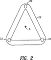
図2は、使用法が図1に示された本発明の好適な実施例に合わせてフィールドトランスデューサを載置したフレームを図示したものである。
図3は、神経外科手術中に使用している本発明の好適な実施例を示すものである。
図4は、使用法が図3に示された本発明の好適な実施例に合わせてフィールドトランスデューサを載置したフレームを図示したものである。
図5は、本発明の好適な実施例によるヒンジ、ジョイント、取付ブラケットの詳細を示す断面図である。
図6Aは、本発明の他の好適な実施例によるフレームの図示したものである。
図6Bは、神経外科手術中に使われている図6Aのフレームを図示したものである。
図7は、本発明のさらに他の好適な実施例によるフレームを図示したものである。
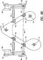
図8Aは、本発明のさらに他の好適な実施例によるフレームを図示したものである。
図8Bは、図8Aの好適な実施例の概略上面図である。
図9は、本発明の他にとるべき好適な実施例を図示したものである。
図10は、本発明のさらに好適な実施例の斜視図であり、腹部または胸部手術に使用しているものである。
図11Aは、本発明のさらに他の好適な実施例の概略正面図である。
図11Bは、図11Aに示される好適な実施例の側面図である。
発明を実施するための最良の形態
本発明の好ましい実施例によれば、図1はカテーテル20などのプローブの位置、方位またはその両方を決定するシステムを示す図であり、そのプローブは心臓カテーテル法の手順中で使用する被検者の体の内部に配置される。
このシステムは国際特許公開第WO 96/05768号に記載されたタイプが好ましく、これは本特許出願の譲受人に譲渡されており、引用文献にてその開示内容がこの文書中に取り入れられている。このシステムはプローブすなわちカテーテル20の遠位端の配置をもたらす手段を含むものである。この開示内容すなわちトランスデューサにおいて使われているように、用語「配置」はプローブすなわちトランスデューサの位置、方位またはその両方をいう。
ここで、プローブは、カテーテルにおいて位置決め可能な用地(site)に隣接した、例えばその遠位端付近に非同心の受信機コイル21(1つのみが示されている)の形状をした複数のトランスデューサを含む。これらのコイルは、フレーム23に固定された参照フィールドトランスデューサ22により生成された磁界に応答して信号を生成し、被検者28の胸部下方にある手術テーブルに対して順に固定されている。これらの信号は6つの位置と方位の座標を考慮したものなので、カテーテル20の配置は同時のイメージングを必要とせずに既知となる。
本発明のこの実施例および他の好適な実施例は6次元配置決定用のシステムに関して記載されているが、本発明は同様に、1次元、2次元、3次元、4次元、または5次元の位置と方位の座標を決定するシステムに適用できる。
本発明の好ましい実施例によれば、図2は本発明の第1の態様の概略図を示しており、3つの参照フィールドトランスデューサ30,32,34が固定されたフレーム22を備える。フレーム22は硬質プラスチックあるいは他の剛性材料からなり、カテーテル挿入中か他の医療処置の最中に参照フィールドトランスデューサの移動を防止するように取り付けられるのが好ましい。トランスデューサ30,32,34はフィールド生成コイルであるのが好ましく、これはフィールド生成回路(図示せず)によって駆動された場合に多数の識別可能な交流(AC)磁界を生成する。トランスデューサ30,32,34によって生成されるそれぞれの磁界は、これらトランスデューサによって定義された三角形の中心を通りその平面に垂直な軸Aに隣接した部分においてほぼ同等で最大の大きさを有するものである。プローブとそれ故カテーテルの位置はこの部位内に最大精度で決定されることが経験的に分かる。
本発明の好ましい実施例においては、トランスデューサ30,32,34によって生成された磁界は異なるAC周波数のおかげで識別可能なものである。トランスデューサはコイルであるのが好ましく、それぞれの共鳴周波数で駆動回路(図示せず)によって駆動され、これらの周波数で実質的に等しい大きさを有する磁界を生成するものである。従来技術において公知のように、それぞれの直径がD1およびD2でそれぞれの周波数がω1およびω2の2つ共鳴コイルが与えられた場合、ω1>ω2かつ双方のコイルが入力レベルが等しく駆動されたならば、その時それぞれの周波数ω1およびω2における磁場の大きさは実質的に等しくなるようにD2はD1よりも一般に大きくならなくてはならない。それ故、例えば図8Bに示されるように、トランスデューサ30,32,34は異なる直径を有するのが好ましく、共鳴周波数が最大であるコイルは最小直径を有し、その逆も同様となる。
本発明の好適な実施例においては、トランスデューサ30,32,34は、二等辺三角形を定義するようにフレーム22に固定される。このフレームが辺に突出しないで手術テーブル24(図1)下に容易に適合できるように、この三角形は等辺ではなくてむしろ他の2つの頂点よりも鋭角となる頂点(apex)を有するのが好ましい。同じ理由のために、三角形の頂点には、コイルのうち最も大きなものが位置づけされる。
図2は、三角形フレーム22と3つのトランスデューサ30,32,34を示す図であるが、本発明の他の好適な実施例は、2つ、4つあるいはそれ以上のトランスデューサを備えていてもよい。さらにまた、トランスデューサが固定されるフレームは、そのフレームの形状はトランスデューサがプローブが配置された体の部分に隣接して安定に位置決めできるようなものである限り、他の多角形でも非多角形の形状をしていてもよく、それは平面あるいは非平面でもよい。このフレームは、プローブを配置した体の部分がトランスデューサの位置によって定義された中心軸に隣接するように位置決めと方向づけをするのが好ましい。公知の手法にしたがって決定されるように、この明細書中の「中心(center)」および「中心の(central)」なる用語は、トランスデューサによりこのような幾何図形が定義されるならば、等多角形の中心あるいはトランスデューサにより定義された図形全体の幾何学的中心をいうように解される。
本発明の他の好適な実施例においては、図3に示されるように、プローブ、好ましくはカテーテル40の被検者44の頭部42内部への配置を決定するシステムは神経外科手術の最中に使用される。図3に示された本発明の好適な実施例はプローブ配置を決定するための他種システムに同様に適用できるが、上述の’103国際特許出願に記載されたタイプが好ましい。フレーム38は被検者44の頭部42に隣接した参照フィールドトランスデューサ30,32,34を保持する。
図4に示されるように、本発明の好適な実施例においては、フレーム38は三角形の二辺をなす剛性アーム36,37からなる。アーム36,37は硬質プラスチックあるいは他の剛性材料から作られているのが好ましい。被検者44の頭部42の後部がアーム36、37間の空間に位置づけできるように、三角形の第3辺は開放されている。このようにして、上記に説明したように、頭部42はカテーテル40の位置が最も精度が高く決定できる部位内に配置されるように、トランスデューサ30,32,34は位置決めされる。
同様に図5を参考にすると、フレーム38は取付ブラケット50によって手術テーブル46に固定され、外科手術中に腰掛け位置に患者を保持するために位置決めされる。頭部の動きを防ぐために、頭部クランプ47はテーブル46に固定されるとともに、頭部42にきつくしっかりと固定される。外科医48は頭部42の前部に手術するのに制約がなく、フレーム38によって妨害されないことが理解されよう。
取付ブラケット50の好適な実施例の詳細は図5の断面図に示される。好ましくは、取付ブラケット50は、テーブル46に堅くテーブル46に結びついたレール54と係合する溝52つきのクランプ51を備える。ちょうねじ56は所望の位置に取付ブラケットを保持するレール54に対してきつく締め付けられる。取付ブラケット50は、ボールジョイントが好ましい固定ジョイント58によってフレーム38に結合される。ジョイント58を所望の角度に位置決めした後、ちょうねじ60はジョイント58を保持するように堅く締め付けられる。
さらにまた、図5に示される本発明の好適な実施例において、調節可能ヒンジ62によりフレーム38のアーム36,37間の角度は調節できるようになる。これらのアームが所望の角度に取り付けられた後、ちょうねじ64はヒンジのさらなる動きを防止するためにきつく締め付けられる。ヒンジ62は光学符号化装置等の公知のタイプの回転測定装置65を含むのが好ましく、これによりアーム36,37間の角度が正確に決定されるようになるので、トランスデューサ30,32,34の相対位置は既知となる。
同様に、本発明によるトランスデューサが固定されるフレームの他の好適な実施例では、被検者の体のある部分に近接してトランスデューサを最適に位置決めするために、フレームのアーム間の角度および変位が、プローブの正確な位置決定のために変えることができるヒンジまたはジョイントを含んでもよい。これらの実施例によるフレームは、当該技術において知られているが、このフレームのアーム間の角度と変位を測定するための手段を含むことができるのが好ましい。
上記に説明されているように、これらのトランスデューサのお互いの相対位置はトランスデューサ間の角度またはトランスデューサを運搬するアームの配置を測定することなどによる幾何学的手法により決定できるが、他の手法を使用してもよい。例えば、これと同日の日付で提出され、本願の譲受人に譲渡された「独立に位置決め可能な位置設定システム(Independently Positionable TransducersFor Location System)」と表題がついた出願に開示されているように、1つ以上の較正フィールドトランスデューサは各参照フィールドトランスデューサと関連して与えることができる。この較正フィールドトランスデューサは、較正および参照フィールドトランスデューサ間の非電離場を送信および検出することによって所望の位置に配置された後、これらフィールドトランスデューサのお互いの相対位置を決定する。このような好適な実施例の一つにおいては、位置決め情報を生成する装置はフレーム上のトランスデューサの各々に隣接しておかれ、これによりこのトランスデューサの相対位置が正確に決定できるようにする。位置情報を生成するためのこれらの装置は、例えば、外部より加えられた磁界に応答して位置応答電気信号を生成したり、フレームに対する装置の位置を決定するように信号分析される感知コイル等のトランスデューサからなってもよい。
本発明の好適な実施例のいくつかにおいては、図6A,図6Bに示されるように、フレーム38は頭部に隣接したアーム36,37の端部に頭部係合固定具70を含む。固定具70は、例えばアーム36,37それぞれのねじ穴を通して固定具70に結合したねじ棒66を進めるためにちょうねじ68を回すことにより、頭部の反対側に対してしっかりとなるように調節されきつく締め付けられる。このようにして、トランスデューサ30,32,34は外科手術の間全体にわたって頭部に相対した固定位置に保持される。さらにまた、この実施例では、フレーム38は同様に、頭部クランプ47に結合して、手術テーブル46に相対した所望の方位に頭部42を保持しておくのに役立つ。
本発明の他の好適な実施例においては、図7に示されるように、トランスデューサ30,32,34は剛性の頭部クランプ71に固定され、これにより本発明に従った放射体を載置したフレームとして利用できる。頭部クランプは、図3に示されるように、頭部クランプ47と同様な方法で患者の頭部にしっかりと固定されるのが好ましい。
図8A,図8Bは本発明の他の好適な実施例を示し、トランスデューサ30,32の位置がしっかりと固定されるのを確保するのに役立ち、外科手術の最中に動かなくなる。図8Aは手術テーブル94に付属したフレーム72を示す図である。フレーム72はトランスデューサ30,32,34が固定された取付台74を含む。図8Bに示されるように、フレーム72はさらに、このフレームの反対側に二組のピンレセプタクル76,78を備え、それぞれヒンジピン80と案内ピン82によって係合している。フレーム72は剛性の単一片材料でできていてもよく、プラスチックが好ましい。
図8Bに示されるように、ヒンジピン80は、一組のピン80によって定義された軸88を中心に回転できるように、フレーム72の両側で案内リング84とホルダ86の穴に係合する。案内ピン82は、フレーム72が軸88中心に回転するとき案内ピン82がスロットに沿って摺動するように案内リング84のスロット90に係合する。ホルダ86は棒92によって係合し、フレーム72および案内リング84を手術テーブル94に結合する。
図8A,図8Bの好適な実施例によれば、ある外科処置の準備段階において、手術テーブル94のマットレス95上に被検者はおかれ、その頭部は頭部支持部96と当接して堅くクランプされたままとなるが、その詳細は図に示されない。フレーム72は、頭部に隣接した望ましい位置で取付台74に固定された放射体を位置決めするように軸88を中心に回転される。次に、つまみ98,100,102,104は所望の方位にフレーム72を堅く保持するようにしっかりと締め付けられる。つまみ98,104はともに棒92の動きを防止する一方、つまみ100はスロット90に案内ピン82をしっかり締め付け、つまみ102はホルダ86におけるヒンジピン80の回転を防止する。このつまみを余分にきつく締めることにより、フレーム72は不意に移動しないように保証する。
図9は本発明の他にとるべき好適な実施例を示す図で、フレーム106は図8A,図8Bに示されるフレーム72に動作において同一である。しかしながら、図9に示される実施例においては、ピン80,82と係合するフレーム106の部分は広くしてある。これはつまみ98,100,102,104をしっかり締めることによって固定される場合に、フレームはより不動な状態でテーブル94に相対したその位置を保持するためである。
フレーム106はさらに、カテーテル較正レセプタクル108を含み、トランスデューサ取付台74に相対した既知の場所に位置決めされる。好ましくは、上記のように、プローブ運搬カテーテルは被検者の体内に挿入される前に、カテーテルはプローブを運搬される遠位先を順にレセプタクル108の各々に置き、レセプタクルのそれぞれの既知の位置をカテーテルの位置情報生成手段により生成される信号から引き出される位置情報と比較することによって較正がなされる。
この手順から導かれた較正データは、「カテーテル較正システム」と表題がついた、オサディ(Osadchy)、フライド(Fried)、ベンハム(Ben-Haim)による未公開の米国暫定特許出願第60/017,634号で、1996年5月17日に提出され、本特許出願の譲受人に譲渡され、この文書中で引用例によりその開示内容が取り入れられているものであるが、これに記載されているように、カテーテル内に蓄えられた較正データと結合して使用できる。
上記の好適な実施例は神経外科手術における使用に対して記載されている。しかしながら、本発明の他の実施例は、閉じた多角形フレームが好都合にしかも安定して外科手術中に位置決めすることができない状況下で、体内の他部分においてプローブあるいはカテーテルの位置を追跡するのに役立てることが可能であることが理解されよう。さらに、本発明の他の好適な実施例では、最適な追跡性能のために、問題になっている体の部分の下というよりもむしろ周囲にトランスデューサを位置決めするのが望ましい場合に役に立つ。
このように、図10に示される本発明の好適な実施例においては、U字形フレーム110はこれに付属したトランスデューサ用の安定取付台を提供し、これは患者128の腹部の内部にプローブを追跡するためのシステムの一部として使うことができる。フレーム110はトランスデューサ122,126がそれぞれ腹部の左側および右側よりも上方に位置決めされ、一方トランスデューサ124は背中よりも下方に位置決めされる。図5に示されるように、フレーム110は取付機構114によって手術テーブル112に接続され、この取付機構114が取付ブラケット50と機能と構成において同様である。機構114によりフレームは左右に傾けることができ、望ましい位置に係止されるまでテーブル112の縦方向に沿って適当に前後に摺動することができる。
上記の好適な実施例の態様はさらに、磁界を基にした位置決定用のシステムについて記載されているが、本発明は、音響、光学あるいは超音波フィールドを放射および検知するなどの他形式のフィールドトランスデューサを使用したシステムなどの、当該技術では知られている他種の位置決定システムに同様に適用可能である。本発明は一般に、放射フィールドが被検者の体の中へ送信されるか、またはそこから受信される医学使用向けの他のシステムに役立つ。
本発明の他の好適な実施例においては、例えば図11A,図11Bに示されるように、「グースネック」小型放射体とも言われる、移動可能トランスデューサセンブリ300が示され、これは好ましくは非常に小さいサイズのフィールド送信コイルであり、フェライトコアを組み込んでもよい1つ以上の参照フィールドトランスデューサ302を含む。小コイルは、プローブ配置計算機によってより正確な計算をもたらす点源双極子(point source dipoles)によりよく似た動作をする傾向があるので、小コイルが好ましい。各コイル302は支持部306を形成するコイル保持アーム304に付属し、プラスチックなどの軽量材料から形成されるのが好ましい。支持部306の中心部には、図11Bに示されるような可撓性のあるグースネックアーム310に支持部が取りつけられるような取付ボルト308がある。全体に可動なトランスデューサアセンブリ300は、調節可能な取付機構312によって手術テーブルなどに取りつけることができ、この取付機構312は締め付けねじ318の回転によって上方アーム316に対してきつく締め付けることができる可動のブラケット314を含む。支持ディスク309はコイル302に対する支持を促進するように任意に含まれる。しかしながら、患者が配置された部屋の照明のせいで望ましくない影が投じられるおそれがある状況では、支持ディスク309は除去できる。トランスデューサ302は3つあるのが好ましいけれども、1つ、2つあるいは3つ以上のトランスデューサでも使用できる。例えば、プローブトランスデューサがフィールド生成トランスデューサからなる場合には、単一の多重軸、固体位置検知器が使用できる。
図11Bに示されるように、1つ以上の患者参照トランスデューサ320は患者322の体に取りつけられ、移動可能トランスデューサがその望ましい位置に移動した後、患者の参照フレームに対して可動なトランスデューサアセンブリ300上のトランスデューサの位置を決定するために使用される。患者参照トランスデューサ320は固体の3軸位置検知器からなるのが好ましい。一旦、移動可能トランスデューサアセンブリが適所に動いたならば、(一つ以上の患者参照トランスデューサ320によって定義されるように)患者参照フレームに対する移動可能トランスデューサセンブリ上のトランスデューサの配置は、患者参照トランスデューサと移動可能トランスデューサセンブリ上の参照フィールドトランスデューサ間の非電離場を送信および受信することによって従来方法で決定できる。
図11A、図11Bに示される移動可能トランスデューサセンブリ300は容易に再位置決め可能な参照フィールドトランスデューサを提供するために使用できる支持部の単なる一例にすぎない。可動で再位置決め可能な支持部を提供する他の手段が採用でき、例えば図5に示されるジョイントやちょうねじ構成などの調節可能かつ締めつけ可能ジョイントによって互いに取りつけられた相当数のより小さめの剛性アーム部材で置き換えることができる。加えて、コイル中の相対位置が既知で決定可能である限り、3つ以上のコイルは移動可能なトランスデューサアセンブリに適用ができ、これらコイルは共面関係に置かれるには及ばない。
この移動可能なトランスデューサアセンブリを使用することにより沢山の利点があとに続く。重要なことだが、移動可能トランスデューサアセンブリは、外科手術の手順中に関心のある部位の近くに移動でき、同様に外科医がアクセスを増加しなければならない領域からも離れて再位置決めすることが可能である。移動可能トランスデューサアセンブリは小さくて直結できるので、したがって、イメージに相関のある特異な組織容量に対して創り出されたフィールドに直結したフィールドトランスデューサ用の調節可能かつ安定な懸架システムを提供できる。
SN比の優れた性能もまた本発明の移動可能トランスデューサセンブリで達成される。一般に、プローブ配置システムにおいて、1つ以上のトランスデューサを使用すれば、当該アセンブリのSN比が最適化され(いわゆる「最適部位」)、より高精度なフィールド測定をすることが可能となる、これらトランスデューサと関連した容量の部位がある。しかしながら、参照トランスデューサが患者のベッド近くの固定位置に載置された従来プローブ配置システムでは、この最適部位は、一般に患者のすみからすみまでをプローブが移動可能となるように大きな領域を網羅する。例えば、カテーテルなどのプローブは患者の足から心臓まで追跡しなければならないならば、固定トランスデューサによって定義された最適部位は患者の大部分を覆うほど大きくなければならない。しかしながら、最適領域が大きくなればなるほど、このような部位のすみからすみまで高SN比を成し遂げることは一層困難になる。本発明の移動可能トランスデューサアセンブリに関しては、外科手術の処置の最中でさえも当該アセンブリが患者の関心ある部位に移動できるので、最適領域はより小さくかつ高度に集中することができる。したがって、本発明の好適な実施例によれば、大きくて固定した配列で同一トランスデューサを使用している固定トランスデューサアセンブリに比較してSN性能が高められたものにすることができる。当該システムのSN性能も同様にプローブトランスデューサの特性に依存する。本発明の好適な実施例によってもたらされる性能の向上により、あまり感度はよくないがその反動でプローブトランスデューサとプローブの小型化を容易にするプローブトランスデューサを使って受容可能なSN性能を提供できる。あるいはまた、移動可能トランスデューサによって与えられた利益は、満足のゆく性能を維持しつつも、より小さく、より安く、しかもあまり押しつけがましくない参照トランスデューサが使用できるようにする。
移動可能トランスデューサセンブリは、助手の外科医の視界を邪魔したり、患者へのアクセスを邪魔したりしないように、最適化して位置決めすることができる。移動可能トランスデューサセンブリは、手術ベッドレールに取りつけることができ、お望みによりこのレールを上下に摺動できる。患者参照トランスデューサは、患者に対する参照フィールドトランスデューサが移動するように提供できるので、先に入手したイメージデータに関する再登録は容易に成し遂げることができる。
さらに、システムソフトウェアも同様に与えることができ、帰還技術は移動可能トランスデューサセンブリの不適当な配置が正確になるように使用できる。例えば、参照フィールドトランスデューサの位置決めがプローブの遠位先の位置決め検知器からあまりにも遠くにあるので信頼できるフィールド検出および位置情報を生成できない場合には、光や音調などの指示器信号が生成できる。
小点源の電磁石を使用すれば有利であるのは、これが軽量であるから故に外科手術処置の間に所望の位置に容易に動かすことができ、あるいは医師の邪魔になったりしないことである。コイルが目下使用されている固定コイルシステムと比較してよりよい双極子としてふるまうので小点源の電磁石を使用すればより正確な計算機がモデル化することもできる。
さらにまた、本発明による移動可能トランスデューサなどのコイル構成に関しては、放射体の平面とマップ化容量との間の分離をインチレベルと同程度まで、さらにはインチの分数レベルまで減少させることが可能である。
本発明のコイルの構成は、固定した、非可動コイルシステムを使用することにより生ずる多数の課題を解決する。例えば、脊髄処置においては、非可動コイルシステムは医師を邪魔するおそれがあり、主要外科医とは反対側に立つ助手の外科医をブロックするおそれがある。非可動コイルシステムは一般に、照明をブロックしてしまうので、患者よりも上方に位置決めすることはできない。また、金属製の患者用ベッドは干渉を生ずるおそれがあり、この問題を解消するために必ずしも全てのベッドが置き換えられたり、装備を改良したりできるわけではないので、非可動コイルシステムは患者の下に位置決めできないおそれがある。このように、現行のシステムは一般に、患者のベッドに平行に与えられ、視界および後方妨害の双方を生ずるおそれがある。その上、非可動コイルに関しては、これが瞬時から瞬時に移動できないならば、高精度のマップ化容量はあまりにも小さくて役立たない。
また、この文書中に記載された本発明の各種の実施例に関しては、例えば、トランスデューサが関心のある領域のより近くに移動してよりよい読み出しを提供することができるようにしたり、トランスデューサがより小さくより集中した領域に現在提供されたので、一層小さめのトランスデューサを使用することができるなどの多数の利点が達成される。これらトランスデューサは同様に特殊な処置のために道を外れて新しい場所に移動することもできる。
同様に、本発明は患者の異なる領域に配置された2つ以上のセットの参照フィールドトランスデューサを同時に使用し、これにより2つ以上の外部参照フレームを効果的に定義できる。この構成は、プローブがこれらトランスデューサセット間を移動するときに、当該システムはしたがってセットのトランスデューサ間を切り替えるように作用する。
同様に、本発明は米国特許出願第08/476,380号に開示されたシステムと結合して使用することができ、その開示内容は引用文献でここに取り入れられている。米国特許出願第08/476,380号においては、適応性のある帰還が使われており、これがプローブの場所にかかわらずプローブ上の検知器が予め選択された大きさの範囲内のフィールドを受信するのを確保するために参照フィールドトランスデューサまたはコイルに供給される電流を調節する。これにより検知器がその最適範囲内で働き、小型の送信機や検知器の使用が可能となる。このようにして、米国特許出願第08/476,380号において開示されている適用性のある帰還技術は本発明で使用でき、参照フィールドトランスデューサとプローブフィールドトランスデューサ間で生成された非電離場の強度を調節する。
本発明はさらに、「体内プローブを使用した医療手法および装置」と表題がつきこれと同一日付で提出され、通例本願の譲受人に譲渡されたPCT出願に開示された「サイト(site)プローブ/インストラメントプローブシステム」と結合して使用できる。このサイトプローブ/インストラメントプローブシステムにおいては、カテーテルなどの医療プローブは、他のプローブに対するこのプローブの相対位置を決定することによって、あるいは同時に、両方のプローブ上に載置されたフィールドトランスデューサに、またはフィールドトランスデューサから非電離放射線を送信することによって、患者の体の内部に案内される。特に、サイトプローブは体の内部の病変に対してしっかりと固定することができ、病変を治療するためにインストラメントプローブはプローブの相対位置をモニターすることによって病変に案内することができる。薬剤または生検を組織標本(tissue sample)に送り出すために、インストラメントプローブをサイトプローブに案内することのみが必要となる可能性があるので、患者内部での医療および/またはイメージングプローブの配置の同時イメージングはされなくてもよい。本発明の各種の移動可能トランスデューサの設備(arrangements)はそれ故、サイトプローブ/インストラメントプローブシステムとともに使用できるが、同時患者イメージングを使用してもしなくてもよく、これにより参照フィールドトランスデューサによって定義された参照フレーム中のプローブの配置を示す(locate)ことができる。
上記に記載された特徴部分のこれらのおよび他の変形および組合せは本発明にもとることなく利用することができるので、好適な実施例の前述の記載は、この特許請求の範囲によって定義された本発明の制限というよりもむしろ例示でなされるべきである。
関連出願の相互参照
本出願は、1996年2月26日付で提出された米国暫定出願第60/012,241号と1996年2月15日付けで提出された米国暫定出願第60/011,720号の利益を請求し、したがってその開示内容はこの文書中で引用文献により取り入れられている。
以下のPCT出願は、各々出願人にバイオセンス社(Biosense,Inc.)の名がついており、同様にこの文書中で引用文献にて取り入れられている:
イスラエル受理官庁に1997年2月14日頃に提出されたカテーテルを基にした外科手術;イスラエル受理官庁に1997年2月14日頃に提出された体内エネルギの集中化(Focusing);イスラエル受理官庁に1997年2月14日頃に提出された位置決定可能な生検針;イスラエル受理官庁に1997年2月14日頃に提出されたカテーテル較正および取扱モニタリング;イスラエル受理官庁に1997年2月14日頃に提出された内視鏡の正確位置決定;米国受理官庁に1997年2月14日頃に提出されたフィールドトランスデューサ付の医療プローブ;米国受理官庁に1997年2月14日頃に提出された管腔付のカテーテル;米国受理官庁に1997年2月14日頃に提出された体内プローブを使用した医療手法および装置;米国受理官庁に1997年2月14日頃に提出されたロケーションシステム用の個別に位置決め可能なトランスデューサ;イスラエル受理官庁に1996年2月14日頃に提出された多重素子エネルギ集中化と表題がついたPCT出願は、出願人としてVictor Spivakと名付けられており、同様にこの文書中に組み込まれている。
本発明に係る実施の態様は以下のとおりである。
1.(a)プローブ内に載置された1つ以上のプローブフィールドトランスデューサを有するプローブと;
(b)フレーム上に載置された1つ以上の参照フィールドトランスデューサと;
(c)前記参照フィールドトランスデューサが患者の体に近接して異なる位置に選択的に位置決めできるように、患者に相対して移動する前記フレームを載置する手段と;
(d)前記プローブフィールドトランスデューサと前記参照フィールドトランスデューサ間の1つ以上の非電離場を送信するための送信手段と;
(e)このような送信されたフィールドを各々検出するための検出手段と;
(f)前記参照フィールドトランスデューサに対する前記プローブの相対的な配置を、検出されたフィールドの特性と、前記参照フィールドトランスデューサとのお互いの相対的な配置とから決定するための計算手段とを備えた患者の体の内部にプローブの配置を決定するシステム。
2.前記フレームは2つ以上の前記参照フィールドトランスデューサが既知の空間関係でお互いに可動であるようにするためのリンク機構を組み入れていることを特徴とする実施態様1に記載のシステム。
3.前記参照フィールドトランスデューサに相対した前記プローブの配置を患者の体に相対した既知の配置に変換するための変換手段をさらに備えたことを特徴とする実施態様1に記載のシステム。
4.前記変換手段は患者の体に取りつけられた1つ以上の基準トランスデューサからなることを特徴とする実施態様3に記載のシステム。
5.前記記載する手段は可撓性アームからなることを特徴とする実施態様1に記載のシステム。
6.(a)プローブの中に載置された1つ以上のプローブフィールドトランスデューサを具備したプローブを与えるステップと;
(b)前記参照フィールドトランスデューサが患者の体に近接して異なる位置に選択的に位置決めできるように、患者に相対して移動するフレームを載置する手段を有する前記フレーム上に載置された1つ以上の参照フィールドトランスデューサを与えるステップと;
(c)前記参照フィールドトランスデューサが患者の体に近接して第1の場所に位置決めされるように前記フレームを調整するステップと;
(d)プローブフィールドトランスデューサと前記参照フィールドトランスデューサ間の1つ以上の非電離場を送信するステップと;
(e)このような送信されたフィールドを各々検出するステップと;
(f)前記参照フィールドトランスデューサに対する前記プローブの相対的な配置を、検出されたフィールドの特性と、参照フィールドトランスデューサとのお互いの相対的な配置とから計算するステップとを備えた患者の体の内部にプローブの配置を決定する方法。
7.前記参照フィールドトランスデューサに相対した前記プローブの配置を患者の体に相対した既知の配置に変換するステップをさらに含むことを特徴とする実施態様6に記載の方法。
8.前記変換ステップは患者の体に1つ以上の基準トランスデューサを付着させるステップと、前記参照フィールドトランスデューサと前記基準トランスデューサ間に送信される非電離場を検出するステップとを含むことを特徴とする実施態様6に記載の方法。
9.(a)1つ以上の参照フィールドトランスデューサと;
(b)前記トランスデューサが固定される剛性フレームであって、前記剛性フレームは、前記参照フィールドトランスデューサが患者の体に近接した異なる場所に選択的に位置決めすることができるように患者に相対して移動する前記フレームを載置する手段からなることとを備えた患者の体の内部に非電離場を生成する装置。
10.前記トランスデューサは多角形を定義し、前記載置手段は多角形面に対して垂直だあり、かつその中心を通過する軸が患者の体を通過するように前記フレームの位置決めを可能にすることを特徴とする実施態様9に記載の装置。
11.前記フレームは体のある部分が実質的に当該多角形の内部に入るように位置決め可能であることを特徴とする実施態様10に記載の装置。
12.載置手段は患者が位置決めされたベッドに堅く結合した載置ブラケットからなることを特徴とする実施態様9に記載の装置。
13.前記載置ブラケットは固定可能ジョイントからなり、これは該フレームが患者のベッドに相対した所望の角度で調整し固定できるように構成されることを特徴とする実施態様12に記載の装置。
14.前記フレームは複数のアームと調節ヒンジとからなり、この調節ヒンジは2つ以上のアームと結合し、結合された2つ以上のアームによって定義された角度となるように構成され、これにより所望の場所に堅く調節し固定することを特徴とする実施態様9に記載の装置。
15.当該フレームは、前記トランスデューサが患者の頭部に近接して固定可能に位置決めされ、その頭部付近で非電離場を生成または受信するように適合することを特徴とする実施態様11に記載の装置。
16.前記フレームは、外科手術中に患者の頭部の位置を固定する装置に機械的に結合されることを特徴とする実施態様15に記載の装置。
17.前記フレームは外科手術中に頭部の位置を固定するのに適合したことを特徴とする実施態様15に記載の装置。
18.前記フレームはさらに、頭部の反対側に位置する頭部係合要素からなることを特徴とする実施態様15に記載の装置。
19.前記トランスデューサはフィールド生成コイルからなることを特徴とする実施態様9に記載の装置。
20.(a)(i)1つ以上の参照フィールドトランスデューサと、(ii)
前記トランスデューサが固定された剛性フレームであって、前記フレームは前記参照フィールドトランスデューサが患者の体に近接して異なる位置に選択的に位置決めできるように患者に相対して動く前記フレームを載置する手段からなることとを備えた非電離場を生成する装置と;
(b)体内に挿入用のプローブと;
(c)このプローブの配置を決定するフィールド応答手段とからなる患者の内部にプローブの配置を決定するシステム。
21.2つ以上の前記参照トランスデューサの相対配置が決定できるように適合した2つ以上の位置検知装置をさらに備えたことを特徴とする実施態様20に記載のシステム。
22.前記フレームはさらに、プローブ較正レセプタクルを備えることを特徴とする実施態様20に記載のシステム。
23.前記フィールド応答手段は前記プローブに固定されることを特徴とする実施態様20に記載のシステム。
24.このフィールドは磁界であり、前記フィールド応答手段はコイルであることを特徴とする実施態様23に記載のシステム。
25.(a)1つ以上の参照フィールドトランスデューサと;
(b)前記トランスデューサが固定された剛性フレームであって、前記フレームはその中に開口部を有しておりこのフレームが患者の頭部または首部の近接し少なくともこの頭部また首部のある部分を部分的に取り囲むように頭部が位置決めできることを備えた医療患者の頭部付近に非電離場を生成する装置。
26.前記フレームは閉じた二辺および開いた一辺を有する三角形を定義する一組のアームを備えており、頭部の一部分が容易に前記開いた一辺を介して前記フレームの内部に位置決めできることを特徴とする実施態様25に記載の装置。
27.前記トランスデューサは三角形フレームの三つの角部に少なくとも位置決めされたことを特徴とする実施態様26に記載の装置。
28.前記アームはヒンジを使用して互いに接続されていることを特徴とする実施態様26に記載の装置。
29.前記アーム部材間の相対的な変位を測定する手段をさらに備えることを特徴とする実施態様28に記載の装置。
30.前記フレームに取りつけた頭部クランプをさらに備えたことを特徴とする実施態様25に記載の装置。
31.前記フレームは頭部の移動を防止するように頭部クランプで一体的に形成されたことを特徴とする実施態様25に記載の装置。
32.前記フレームは頭部に対してしっかり締めるように調節可能な頭部係止固定具をさらに含むことを特徴とする実施態様25に記載の装置。
産業上の利用性
本発明は医療およびその関連手技にて使用できる。 Technical field
The present invention relates to medical diagnostic and therapeutic systems, and more particularly to a reference field transducer (probe field transducer) for detecting the position, orientation, or both of a probe within the body of a subject. Reference field transducers) and medical probe usage.
Background art
There are many medical techniques for introducing a probe, such as a catheter, into the body of a subject or patient. In procedures such as cardiac catheterization and neurosurgery, a physician or surgeon often needs to know the position of the distal end of the probe within the body. For this purpose, imaging methods such as fluoroscopic diagnosis and ultrasonic diagnosis are used, but they are not always practical or preferable. For example, such devices generally require continuous imaging of the probe and patient during the procedure. In addition, fluoroscopy systems are often undesirable because they expose patients and physicians to significant amounts of ionizing radiation.
Many position detection systems for detecting the position of a probe or catheter tip in a patient's body, which do not require continuous imaging of the patient, have been proposed. These systems include, for example, US Pat. Nos. 5,558,091, 5,391,199, 5,443,489, and International Patent Publication Nos.
The systems disclosed in US Pat. Nos. 5,558,091, 5,391,199, 5,443,489, and International Patent Publication No.
For example, as described in US Pat. No. 5,558,091 mentioned above, the reference frame of the external field transducer includes magnetic resonance imaging data, computer (X-ray body axis) tomography (“CAT”) data, It can be registered with a reference frame of imaging data, such as conventional X-ray imaging data, so that the position and / or orientation derived from the system can be displayed superimposed on the patient's body image as a representation of the probe. The doctor can use this information to guide the probe to a desired location within the patient's body and monitor its location and orientation while treating or measuring internal body structures. This arrangement greatly enhances the ability of the physician to navigate the distal end of the probe through the body structure and is significant over conventional methods in which the probe is steered into the body simply by touch. Offer a great advantage. For navigation purposes, an optical image of the surrounding tissue need not be acquired and can be used with a probe that is too small to accommodate the optical element. The systems based on these transducers also avoid the difficulties associated with probe navigation by continuously imaging the probe and patient during the procedure, e.g. inherent in fluoroscopy systems. This avoids prolonged irradiation with ionizing radiation.
Such systems typically utilize a reference field transducer or coil and are provided in a fixed array fixed in a location such as the ceiling of the operating room or secured to a surgical or catheter insertion table. In medical applications, if the system is used to track the position of the probe inside the patient's body, coil placement can also prevent the physician from having free access to the patient. There is.
For example, International Patent Publication No.
In order to detect the position and orientation of a catheter or probe inserted into the brain, a transducer or field radiating coil is preferably placed adjacent to the patient's head. However, in neurosurgery, patients are often seated and are in a position where their backs are stretched or face-down. Thus, the triangular frame holding the three radiators as described above cannot be easily fixed and positioned below the head. However, positioning the frame above or near the head generally interferes with the surgeon's successful handling of the probe and surgical tool.
Therefore, probe tracking systems such as those described above and other types of systems that inevitably involve applying electromagnetic or other non-ionizing energy fields to the human body can be achieved by adjusting and optimizing the reference field transducer. It is desirable to improve accuracy and efficiency. As with neurosurgery, if the transducer is constrained to a fixed position with a triangle or other mounting frame, it may not be possible to achieve optimal positioning. For example, if the probe is to track the interior of a patient's abdomen, it may be desirable to place the radiator at a fixed, known location around the abdomen rather than under the patient's back.
In addition, it is desirable to provide greater flexibility when the transducer is placed near the subject. This increased placement adaptability allows the physician easier access to the patient. Due to its adaptability to transducer placement, conventional positioning of the transducer moves the transducer to the closest possible position so as to increase the sensitivity of the positioning system.
Disclosure of the invention
The present invention addresses the need to provide greater flexibility to positioning a positioning transducer by providing a system for determining probe placement within a patient's body, wherein the system is within the probe. A probe having one or more probe field transducers mounted thereon and one or more reference field transducers mounted on a frame. The system includes means for mounting a frame that moves relative to the patient so that the reference field transducer can be selectively positioned at different locations in proximity to the patient's body. This attachment means preferably comprises a flexible gooseneck arm.
A transmitting means is then provided to transmit one or more non-ionizing fields between the probe field transducer and the reference field transducer. Finally, the computing means determines the relative placement of the probe relative to the reference field transducer from the detected field characteristics and the relative placement of the reference field transducers with respect to each other.
In the preferred embodiment, more than one reference field transducer is provided, and the frame incorporates a linkage so that each of the reference field transducers is movable relative to each other in a known spatial relationship.
In another preferred embodiment, one or more reference transducers attached to the patient's body convert the probe placement relative to the reference field transducer to a known placement relative to the patient body.
In a method according to a preferred embodiment of the present invention, the placement of the probe inside the patient's body comprises (a) providing a probe with one or more probe field transducers mounted within the probe; (b) One or more reference field transducers mounted on a frame having means for mounting a frame that moves relative to the patient so that the reference field transducer can be selectively positioned at different locations in proximity to the patient's body. And (c) adjusting the frame so that the reference field transducer is positioned at a first location in proximity to the patient's body; and (d) between the probe field transducer and the reference field transducer. Transmitting one or more non-ionization fields; (e) Detecting each of the transmitted fields, such as: (f) the relative placement of the probe with respect to the reference field transducer, from the characteristics of the detected field and the relative placement of the reference field transducers with respect to each other. And calculating step.
In a preferred method, the present invention further includes the step of translating the probe placement relative to the reference field transducer to a known placement relative to the patient's body. Preferably, the converting step includes attaching one or more reference transducers to the patient's body and detecting a non-ionizing field transmitted between the reference field transducer and the reference transducer.
Similarly, an object of the present invention is to provide a fixed frame for holding a reference field transducer for use in determining the placement of a probe within a subject's body during a medical or surgical procedure. is there. In one aspect of the invention, the frame is suitable for positioning the reference field transducer close to the subject's head without interfering with the neurosurgical procedure.
A further object of the present invention is that this frame can be quickly and conveniently fixed to a desired location for optimal transmission of a non-ionizing field in a part of a subject, preferably its body part. And then quickly remove it from its position.
In a preferred embodiment of the present invention, a device for generating a non-ionizing energy field that is useful for determining the placement of a probe inside the body, comprising two or more reference field transducers, This allows the reference field transducer to be fixed to a rigid frame that can be stably positioned at an optimal location close to the part of the body in which the probe is inserted so that the placement of the probe can be accurately determined. In a preferred embodiment of the present invention, the reference field transducer is a radiator coil that generates an electromagnetic field.
In some preferred embodiments of the present invention, an apparatus for generating a non-ionizing field comprises three transducers or coils fixed to a rigid frame. Preferably, the frame is conveniently and stably positioned below the rib cage or abdomen, which is done during probe insertion. In another preferred embodiment of the present invention, for use in neurosurgery, the field generating device comprises three coils secured to a frame below the head in proximity to the head. Preferably, the frame includes an opening adapted for mounting around the head or neck.
In the preferred embodiment of the present invention, more generally, three or more coplanar reference field transducers define a polygon shape, which corresponds to the vertex of the polygon. The section of the frame corresponding to a side of the polygon is open, and the frame is positioned so that a part of the body is partly included in this open section. The frame may include a mounting bracket that is securely coupled to a surgical table, bed, or other device used to fix the position of the subject.
In some preferred embodiments of the present invention, the frame is coupled to a device for securing the subject's head during neurosurgery. In one such preferred embodiment, one or more reference field transducers are secured to the head fixation device. The electromagnetic fields generated by the transducers cause them to generate position-responsive electrical signals that are analyzed to determine and confirm the position of the device relative to the frame. Furthermore, in some of such preferred embodiments of the present invention, the frame or head fixation device further includes a predetermined known location marked thereon for insertion into the body. These probes are initially placed in these locations for calibration and reference positioning.
In addition, in some of the preferred embodiments of the present invention, the mounting bracket includes a fixable joint so that the angular orientation of the frame relative to the bed or relative to the head fixation device can be adjusted. And then fixed at the desired angle. In some preferred embodiments, the frame comprises one or more adjustment hinges. Each such hinge can be bent to adjust the angle between two sides of the frame adjacent to it.
In some preferred embodiments of the present invention, the frame comprises a headrest fixture. The position of the fixture is such that the fixture fits well against the head so that the head is held in a fixed position relative to the reference field transducer to prevent head movement relative to the frame. Can be adjusted.
Therefore, according to a preferred embodiment of the present invention, there is provided an apparatus for generating a non-ionization field inside a subject's body, the apparatus comprising a plurality of reference field transducers for generating the non-ionization field, and these And a rigid frame to which the transducer is fixed. The rigid frame is configured so that the reference field transducer can be firmly positioned close to the body. Preferably, the transducer defines a polygon and the frame is configured to be positioned so that an axis passing through the center of the frame is perpendicular to the polygon plane. Furthermore, the frame is preferably configured such that a body part can be positioned so as to be substantially within the polygon.
Preferably, the frame includes a mounting bracket that securely couples to the surgical table or bed. The mounting bracket preferably includes a fixable joint configured such that the frame can be adjusted and fixed at a desired angle relative to the surgical table or bed. Furthermore, the frame preferably includes a plurality of arms and an adjustment hinge coupled to the two or more arms, wherein the angle defined by the coupled two or more arms is adjusted to a desired position and secured securely. Configured to be able to.
The preferred embodiment of the present invention provides that the frame is adapted so that the reference field transducer is firmly positioned close to the head and generates a non-ionizing field near the head. Preferably, the frame is mechanically coupled to a device that fixes the position of the head during surgery. Alternatively, the frame can be adapted to fix the head position during surgery. The frame may further comprise a head engaging element located on the opposite side of the head. The transducer is preferably a coil that generates a magnetic field.
Further in accordance with a preferred embodiment of the present invention, there is provided a system for determining the position and orientation of a probe within a subject's body, the system comprising: a device for generating a field as described above; And at least one device corresponding to the field for determining the position and orientation coordinates of the probe. Preferably, the system includes one or more position sensing devices, preferably fixed to the probe and adapted to determine the position of the transducer. Preferably, the field is a magnetic field and the field responder is a coil. Similarly, this frame preferably further includes probe calibration receptacles.
Furthermore, preferred embodiments of the present invention include a device that generates a non-ionizing field near the head of a medical patient, the device including one or more reference field transducers and a rigid frame to which the transducer is secured. The frame has an opening therein and the head can be positioned so that the frame is adjacent to and surrounds at least a portion of the patient's head or neck.
The frame preferably includes a set of arm members defining a triangle having two closed sides and one open side, so that a portion of the head or neck can be easily positioned within the frame through the open side. Preferably, the transducer is positioned at at least three corners of the frame, and the arm members of the frame are connected to each other using hinges. Furthermore, a means for measuring the relative displacement between the arm members can be provided.
In other preferred embodiments, the head clamp can be attached to the frame to prevent movement of the head. In other suitable arrangements, the frame may be formed integrally with the head clamp to prevent head movement. In other preferred embodiments, the frame may further include a head engagement fixture that is adjustable to tension against the head.
[Brief description of the drawings]
FIG. 1 shows a preferred embodiment of the present invention used during arterial catheter insertion.
FIG. 2 illustrates a frame on which a field transducer is mounted in accordance with the preferred embodiment of the present invention shown in FIG.
FIG. 3 shows a preferred embodiment of the present invention being used during neurosurgery.
FIG. 4 illustrates a frame on which a field transducer is mounted in accordance with the preferred embodiment of the present invention shown in FIG.
FIG. 5 is a cross-sectional view showing details of a hinge, joint, and mounting bracket according to a preferred embodiment of the present invention.
FIG. 6A is an illustration of a frame according to another preferred embodiment of the present invention.
FIG. 6B illustrates the frame of FIG. 6A being used during neurosurgery.
FIG. 7 illustrates a frame according to still another preferred embodiment of the present invention.
FIG. 8A illustrates a frame according to still another preferred embodiment of the present invention.
FIG. 8B is a schematic top view of the preferred embodiment of FIG. 8A.
FIG. 9 illustrates a preferred embodiment other than the present invention.
FIG. 10 is a perspective view of a further preferred embodiment of the present invention for use in abdominal or thoracic surgery.
FIG. 11A is a schematic front view of yet another preferred embodiment of the present invention.
FIG. 11B is a side view of the preferred embodiment shown in FIG. 11A.
BEST MODE FOR CARRYING OUT THE INVENTION
In accordance with a preferred embodiment of the present invention, FIG. 1 illustrates a system for determining the position, orientation, or both of a probe, such as
This system is preferably of the type described in International Patent Publication No. WO 96/05768, which is assigned to the assignee of the present patent application, the disclosure of which is incorporated herein by reference. . The system includes a probe or means for providing placement of the distal end of the
Here, the probe is a plurality of transducers in the shape of a non-concentric receiver coil 21 (only one shown) adjacent to a site positionable in the catheter, for example near its distal end. including. These coils generate signals in response to the magnetic field generated by the
Although this and other preferred embodiments of the present invention are described with respect to a system for 6-dimensional placement determination, the present invention is similarly applied to one-dimensional, two-dimensional, three-dimensional, four-dimensional or five-dimensional It can be applied to a system that determines coordinates of position and orientation.
In accordance with a preferred embodiment of the present invention, FIG. 2 shows a schematic diagram of the first aspect of the present invention, comprising a
In the preferred embodiment of the present invention, the magnetic fields generated by the
In the preferred embodiment of the present invention, the
Although FIG. 2 shows a
In another preferred embodiment of the present invention, as shown in FIG. 3, a system for determining the placement of a probe, preferably a
As shown in FIG. 4, in the preferred embodiment of the present invention, the
Similarly, referring to FIG. 5, the
Details of the preferred embodiment of the mounting
Furthermore, in the preferred embodiment of the present invention shown in FIG. 5, an
Similarly, in another preferred embodiment of the frame to which the transducer according to the invention is fixed, the angle and displacement between the arms of the frame in order to optimally position the transducer close to a part of the subject's body. May include hinges or joints that can be changed for accurate positioning of the probe. Frames according to these embodiments are known in the art, but preferably can include means for measuring the angle and displacement between the arms of the frame.
As explained above, the relative position of these transducers to each other can be determined by geometric techniques, such as by measuring the angle between the transducers or the placement of the arms carrying the transducers, but other techniques can be used. May be. For example, as disclosed in the application entitled `` Independently Positionable Transducers For Location System '' filed on the same date and assigned to the assignee of the present application, One or more calibration field transducers can be provided in association with each reference field transducer. The calibration field transducer is positioned at the desired location by transmitting and detecting a non-ionizing field between the calibration and reference field transducers and then determines the relative position of the field transducers with respect to each other. In one such preferred embodiment, a device for generating positioning information is adjacent to each of the transducers on the frame so that the relative position of the transducer can be accurately determined. These devices for generating position information include, for example, a sensing coil that generates a position-responsive electrical signal in response to an externally applied magnetic field, or a signal analysis that determines the position of the device relative to the frame It may be composed of a transducer.
In some of the preferred embodiments of the present invention, as shown in FIGS. 6A and 6B, the
In another preferred embodiment of the present invention, as shown in FIG. 7, the
FIGS. 8A and 8B illustrate another preferred embodiment of the present invention, which helps to ensure that the position of the
As shown in FIG. 8B, the hinge pins 80 engage the holes in the
According to the preferred embodiment of FIGS. 8A and 8B, a subject is placed on the
FIG. 9 is a diagram showing a preferred embodiment other than the present invention. The
The calibration data derived from this procedure is unpublished US Provisional Patent Application No. 60/017, Osadchy, Fried, Ben-Haim, entitled “Catheter Calibration System”. No. 634, filed May 17, 1996, assigned to the assignee of the present patent application, the disclosure of which is incorporated by reference in this document. Thus, it can be used in combination with calibration data stored in the catheter.
The preferred embodiment described above has been described for use in neurosurgery. However, other embodiments of the present invention track the position of the probe or catheter in other parts of the body in situations where a closed polygon frame cannot be conveniently and stably positioned during surgery. It will be understood that it can be useful. In addition, other preferred embodiments of the invention are useful when it is desirable to position the transducer around rather than under the body part in question for optimal tracking performance.
Thus, in the preferred embodiment of the present invention shown in FIG. 10, the
While aspects of the preferred embodiment described above are further described for a system for position determination based on a magnetic field, the present invention is directed to other types of fields, such as emitting and detecting acoustic, optical or ultrasonic fields. It is equally applicable to other types of position determination systems known in the art, such as systems using transducers. The present invention is generally useful for other systems for medical use in which a radiation field is transmitted into or received from a subject's body.
In another preferred embodiment of the present invention, there is shown a
As shown in FIG. 11B, one or more
The
Many advantages follow by using this movable transducer assembly. Importantly, the movable transducer assembly can be moved closer to the site of interest during the surgical procedure and can also be repositioned away from the area where the surgeon must increase access. is there. The movable transducer assembly is small and can be directly coupled, thus providing an adjustable and stable suspension system for field transducers directly coupled to the field created for the specific tissue volume correlated to the image.
Excellent performance in signal to noise ratio is also achieved with the movable transducer assembly of the present invention. In general, the use of one or more transducers in a probe placement system optimizes the signal-to-noise ratio of the assembly (so-called “optimal site”) and allows these transducers to perform more accurate field measurements. There is a site of capacity related to. However, in conventional probe placement systems where the reference transducer is placed in a fixed position near the patient's bed, this optimal site generally covers a large area so that the probe can move from corner to corner of the patient. For example, if a probe such as a catheter must be tracked from the patient's foot to the heart, the optimal site defined by the fixed transducer must be large enough to cover the majority of the patient. However, as the optimum region becomes larger, it becomes more difficult to achieve a high signal-to-noise ratio from the end of such a region. With the movable transducer assembly of the present invention, the optimal area can be smaller and highly concentrated because the assembly can be moved to the site of interest of the patient even during a surgical procedure. Thus, according to the preferred embodiment of the present invention, the SN performance can be enhanced as compared to a fixed transducer assembly using the same transducer in a large and fixed array. The SN performance of the system also depends on the characteristics of the probe transducer. The improved performance provided by the preferred embodiment of the present invention can provide acceptable SN performance using a probe transducer that is less sensitive but whose recoil facilitates miniaturization of the probe transducer and probe. Alternatively, the benefits provided by the movable transducer allow the use of a reference transducer that is smaller, cheaper, and less intrusive while maintaining satisfactory performance.
The movable transducer assembly can be optimized and positioned so as not to obstruct the assistant surgeon's field of view or obstruct access to the patient. The movable transducer assembly can be attached to a surgical bed rail and can be slid up and down as desired. Because the patient reference transducer can be provided to move the reference field transducer for the patient, re-registration for previously obtained image data can be easily accomplished.
In addition, system software can be provided as well, and feedback techniques can be used so that improper placement of the movable transducer assembly is accurate. For example, if the positioning of the reference field transducer is too far away from the positioning detector distal to the probe to produce reliable field detection and position information, indicator signals such as light and tone can be generated.
The advantage of using a small-point source electromagnet is that it is lightweight and therefore can be easily moved to the desired position during the surgical procedure or does not interfere with the physician. A more accurate calculator can be modeled by using a small point source electromagnet because the coil behaves as a better dipole compared to the fixed coil system currently used.
Furthermore, for coil configurations such as movable transducers according to the present invention, the separation between the plane of the radiator and the mapped capacitance can be reduced to as little as an inch level, or even to a fractional level of inches. is there.
The coil configuration of the present invention solves a number of problems arising from the use of a fixed, non-movable coil system. For example, in a spinal procedure, a non-moving coil system can interfere with a physician and can block an assistant surgeon standing opposite the primary surgeon. Non-moving coil systems generally block illumination and cannot be positioned above the patient. Also, metal patient beds can cause interference, and not all beds can be replaced or equipment can be improved to eliminate this problem, so the non-movable coil system can be May not be able to position below. As such, current systems are generally provided parallel to the patient's bed and can cause both visibility and posterior obstruction. Moreover, for non-movable coils, if this cannot be moved from moment to moment, the high-precision mapping capacity is too small to be useful.
Also, with respect to the various embodiments of the invention described in this document, for example, the transducer can be moved closer to the region of interest to provide a better readout, Numerous advantages are achieved, such as the ability to use smaller transducers, since they are currently provided in smaller and more concentrated areas. These transducers can also be moved off the road to new locations for special treatments as well.
Similarly, the present invention can simultaneously use two or more sets of reference field transducers located in different areas of the patient, thereby effectively defining two or more external reference frames. This configuration serves to switch between the transducers of the set as the probe moves between the transducer sets.
Similarly, the present invention can be used in conjunction with the system disclosed in US patent application Ser. No. 08 / 476,380, the disclosure of which is hereby incorporated by reference. In US patent application Ser. No. 08 / 476,380, adaptive feedback is used, which allows a detector on the probe to receive a field within a preselected size range regardless of the location of the probe. Adjust the current supplied to the reference field transducer or coil to ensure that. This allows the detector to work within its optimal range, allowing the use of small transmitters and detectors. In this way, the applicable feedback technique disclosed in US patent application Ser. No. 08 / 476,380 can be used with the present invention, and the intensity of the non-ionization field generated between the reference field transducer and the probe field transducer. Adjust.
The present invention further includes a “site probe / device” filed on the same date and entitled “Medical Techniques and Devices Using Intracorporeal Probes” and typically disclosed in PCT applications assigned to the assignee of the present application. It can be used in combination with the “Instrument Probe System”. In this site probe / instrument probe system, a medical probe, such as a catheter, either by determining the relative position of this probe relative to other probes, or simultaneously, on field transducers mounted on both probes, or It is guided inside the patient's body by transmitting non-ionizing radiation from the field transducer. In particular, the site probe can be firmly fixed to a lesion inside the body, and the instrument probe can be guided to the lesion by monitoring the relative position of the probe to treat the lesion. In order to deliver a drug or biopsy to a tissue sample, it may only be necessary to guide the instrument probe to the site probe, so the placement of the medical and / or imaging probe inside the patient. Simultaneous imaging may not be performed. The various movable transducer arrangements of the present invention can therefore be used with a site probe / instrument probe system, but may or may not use simultaneous patient imaging, which is defined by the reference field transducer. The location of the probe in the reference frame can be located.
Since these and other variations and combinations of the features set forth above can be utilized without departing from the invention, the foregoing description of the preferred embodiments has been defined by the following claims. It should be done by way of illustration rather than limitation of the invention.
Cross-reference of related applications
This application claims the benefit of US Provisional Application No. 60 / 012,241 filed February 26, 1996 and US Provisional Application No. 60 / 011,720 filed February 15, 1996. The disclosure content thereof is therefore incorporated by reference in this document.
The following PCT applications are each named by the name of Biosense, Inc. and are also incorporated by reference in this document:
Surgery based on a catheter submitted to the Israeli receiving agency around February 14, 1997; Focusing on internal energy (Focusing) submitted to the Israeli receiving agency around February 14, 1997; Positionable biopsy needles submitted around 14 February 1997; catheter calibration and handling monitoring submitted to the Israeli receiving office around 14 February 1997; submitted to the Israeli receiving office around 14 February 1997 Determining the correct position of the endoscope; Medical probe with a field transducer submitted to the US receiving office around February 14, 1997; Catheter with a lumen submitted to the US receiving office around February 14, 1997; Medical procedures and devices using in-vivo probes submitted to the receiving Office around February 14, 1997; Individually positionable transducers for location systems filed with the Office of Government on February 14, 1997; PCT applications with multi-element energy concentration and title filed with the Israeli Office of Government on February 14, 1996 Is named Victor Spivak as applicant and is incorporated into this document as well.
Embodiments according to the present invention are as follows.
1. (A) a probe having one or more probe field transducers mounted within the probe;
(B) one or more reference field transducers mounted on the frame;
(C) means for mounting the frame that moves relative to the patient so that the reference field transducer can be selectively positioned at different positions in proximity to the patient's body;
(D) transmitting means for transmitting one or more non-ionizing fields between the probe field transducer and the reference field transducer;
(E) detection means for detecting each such transmitted field;
(F) a patient comprising calculation means for determining the relative placement of the probe relative to the reference field transducer from the characteristics of the detected field and the relative placement of the probe relative to the reference field transducer; System to determine the placement of the probe inside the body of the body.
2. 2. The system of embodiment 1 wherein the frame incorporates a linkage mechanism to allow two or more of the reference field transducers to move relative to each other in a known spatial relationship.
3. 2. The system of embodiment 1, further comprising conversion means for converting the probe placement relative to the reference field transducer to a known placement relative to a patient's body.
4). 4. The system of embodiment 3, wherein the converting means comprises one or more reference transducers attached to the patient's body.
5. The system of embodiment 1 wherein the means for describing comprises a flexible arm.
6). (A) providing a probe comprising one or more probe field transducers mounted in the probe;
(B) 1 mounted on the frame having means for mounting a frame that moves relative to the patient so that the reference field transducer can be selectively positioned at different positions in proximity to the patient's body; Providing one or more reference field transducers;
(C) adjusting the frame such that the reference field transducer is positioned at a first location proximate to a patient's body;
(D) transmitting one or more non-ionization fields between a probe field transducer and the reference field transducer;
(E) detecting each such transmitted field;
(F) calculating the relative placement of the probe with respect to the reference field transducer from the characteristics of the detected field and the relative placement of the probe with respect to the reference field transducer; To determine the placement of the probe.
7). 7. The method of embodiment 6, further comprising converting the probe placement relative to the reference field transducer into a known placement relative to a patient's body.
8). An embodiment wherein the converting step includes attaching one or more reference transducers to a patient's body and detecting a non-ionization field transmitted between the reference field transducer and the reference transducer. 6. The method according to 6.
9. (A) one or more reference field transducers;
(B) a rigid frame to which the transducer is fixed, wherein the rigid frame moves relative to the patient so that the reference field transducer can be selectively positioned at different locations close to the patient's body. An apparatus for generating a non-ionization field inside a patient's body comprising: means for mounting the frame.
10. The transducer defines a polygon, and the positioning means is perpendicular to the polygonal plane and allows the frame to be positioned such that an axis passing through its center passes through the patient's body. Embodiment 10. The apparatus of embodiment 9 characterized.
11. 11. The apparatus of embodiment 10, wherein the frame is positionable so that a body part is substantially within the polygon.
12 10. The apparatus of embodiment 9, wherein the mounting means comprises a mounting bracket that is rigidly coupled to the bed in which the patient is positioned.
13. 13. The apparatus of embodiment 12, wherein the mounting bracket comprises a fixable joint that is configured such that the frame can be adjusted and fixed at a desired angle relative to the patient's bed.
14 The frame comprises a plurality of arms and an adjustment hinge, the adjustment hinge being coupled to two or more arms and configured to have an angle defined by the two or more arms coupled, thereby providing a desired Embodiment 10. The device of embodiment 9, wherein the device is tightly adjusted and secured in place.
15. 12. The apparatus of embodiment 11, wherein the frame is adapted to position the transducer in a fixed manner close to a patient's head and to generate or receive a non-ionizing field near the head. .
16. 16. The apparatus of embodiment 15, wherein the frame is mechanically coupled to a device that fixes the position of the patient's head during surgery.
17. 16. The apparatus of embodiment 15, wherein the frame is adapted to fix the position of the head during surgery.
18. 16. The apparatus of embodiment 15, wherein the frame further comprises a head engaging element located on the opposite side of the head.
19. The apparatus of claim 9, wherein the transducer comprises a field generating coil.
20. (A) (i) one or more reference field transducers; and (ii)
Means for mounting the frame that moves relative to the patient so that the transducer can be selectively positioned at different positions in close proximity to the patient's body. A device for generating a non-ionizing field comprising:
(B) a probe for insertion into the body;
(C) A system for determining the placement of the probe inside the patient, comprising field response means for determining the placement of the probe.
21. The system of
22. 21. The system of
23. 21. The system of
24. 24. The system of
25. (A) one or more reference field transducers;
(B) a rigid frame to which the transducer is fixed, the frame having an opening in the frame, wherein the frame is adjacent to a patient's head or neck and at least a portion of the head or neck. An apparatus for generating a non-ionization field near a medical patient's head, wherein the head can be positioned to partially surround.
26. The frame includes a pair of arms defining a triangle having two closed sides and one open side, and a portion of the head can be easily positioned within the frame through the open side. An apparatus according to embodiment 25.
27. 27. The apparatus of
28. 27. The apparatus of
29. 29. The apparatus according to
30. 26. The apparatus of embodiment 25, further comprising a head clamp attached to the frame.
31. 26. The apparatus of embodiment 25, wherein the frame is integrally formed with a head clamp to prevent head movement.
32. 26. The apparatus of embodiment 25, wherein the frame further comprises a head locking fixture adjustable to tighten against the head.
Industrial availability
The present invention can be used in medical and related procedures.
Claims (5)
(a)プローブ内に搭載された1つ以上のプローブフィールドトランスデューサを有する前記プローブと、
(b)フレーム上に搭載された1つ以上の参照フィールドトランスデューサと、
(c)前記参照フィールドトランスデューサが患者の体に近接して異なる位置に選択的に位置決めできるように、患者に対して移動する前記フレームを搭載する手段と、
(d)前記プローブフィールドトランスデューサと前記参照フィールドトランスデューサ間で1つ以上の非電離フィールドを送信するための送信手段と、
(e)このような送信されたフィールドを各々検出するための検出手段と、
(f)前記参照フィールドトランスデューサに対する前記プローブの相対的な配置を、検出されたフィールドの特性と、前記参照フィールドトランスデューサのお互いの相対的な配置とから決定するための計算手段と、
(g)前記参照フィールドトランスデューサに対する前記プローブの配置を患者の体に対する既知の配置に変換するための変換手段と、
を具備し、
前記変換手段は、当該患者の体に付着し得る1つ以上の基準トランスデューサを含み、
前記1つ以上の参照フィールドトランスデューサの配置は、前記1つ以上の基準トランスデューサと前記1つ以上の参照フィールドトランスデューサとの間で非電離場を送信および受信することにより決定される、システム。 In a system for determining the placement of a probe in a patient's body,
(A) and the probe having one or more probe field transducers mounted in the probe,
(B) one or more reference field transducers mounted on a frame,
(C) as the reference field transducers can be selectively positioned in different positions in close proximity to the patient's body, means for mounting the frame to move against the patient,
And (d) transmitting means for transmitting one or more non-ionizing fields between said probe field transducers and said reference field transducers,
(E) detection means for detecting each such transmitted field ;
(F) the relative disposition of the probe relative to the reference field transducers, and characteristics of the detected field, and calculating means for determining from the relative positioning of each other of said reference field transducin Sa,
(G) the arrangement of the probe relative to the reference field transducer and converter means for converting the arrangement of known against the patient's body,
Comprising
And the converting means, viewed contains one or more reference transducers which may be attached to the body of the patient,
The arrangement of one or more reference field transducers is determined by transmitting and receiving non-ionizing fields between the one or more reference transducers and the one or more reference field transducers, the system.
前記1つ以上の参照フィールドトランスデューサは、お互いに既知の空間関係にある、システム。 The system of claim 1, wherein
The one or more reference field transducers are in a known spatial relationship to each other, the system.
前記フレームは剛性であり、前記参照フィールドトランスデューサをお互いに対して固定位置に把持する、システム。 The system of claim 1, wherein
The frame is rigid, gripped in a fixed position to the reference field transducers with respect to one another, the system.
前記搭載する手段は可撓性アームを備える、システム。 The system of claim 1, wherein
It said means for mounting comprises a flexible arm, system.
(a)プローブ内に搭載された1つ以上のプローブフィールドトランスデューサを有する前記プローブと、
(b)フレーム上に搭載された1つ以上の参照フィールドトランスデューサと、
(c)前記参照フィールドトランスデューサが患者の体に近接して異なる位置に選択的に位置決めできるように、患者に対して移動する前記フレームを搭載する手段と、
(d)前記プローブフィールドトランスデューサと前記参照フィールドトランスデューサ間で1つ以上の非電離フィールドを送信するための送信手段と、
(e)このような送信されたフィールドを各々検出するための検出手段と、
(f)前記参照フィールドトランスデューサに対する前記プローブの相対的な配置を、検出されたフィールドの特性と、前記参照フィールドトランスデューサのお互いに相対的な配置とから決定するための計算手段と、
(g)前記参照フィールドトランスデューサに対する前記プローブの配置を患者の体に対する既知の配置に変換するための変換手段と、
を具備し、
前記変換手段は、患者に対する前記参照フィールドトランスデューサの配置を決定する手段を含み、
前記配置を決定する手段は、当該患者の体に付着し得る1つ以上の患者参照トランスデューサを含み、患者に対する参照フィールドトランスデューサの配置に基づき、患者に対するプローブの配置を算定し、
前記参照フィールドトランスデューサの配置は、前記1つ以上の患者参照トランスデューサと前記参照フィールドトランスデューサとの間で非電離フィールドを送信および受信することにより決定される、システム。 In a system for determining the placement of a probe in a patient's body,
(A) and the probe having one or more probe field transducers mounted in the probe,
(B) one or more reference field transducers mounted on a frame,
(C) as the reference field transducers can be selectively positioned in different positions in close proximity to the patient's body, means for mounting the frame to move against the patient,
And (d) transmitting means for transmitting one or more non-ionizing fields between said probe field transducers and said reference field transducers,
(E) detection means for detecting each such transmitted field ;
(F) the relative disposition of the probe relative to the reference field transducers, and characteristics of the detected field, and calculating means for determining from the relative disposition to one another of the reference field transducin Sa,
(G) the arrangement of the probe relative to the reference field transducer and converter means for converting the arrangement of known against the patient's body,
Comprising
The converting means includes means for determining an arrangement of the reference field transducer relative to a patient;
Wherein the means for determining the arrangement includes one or more patient reference transducers may be attached to the body of the patient, based on the arrangement of the reference field transducer against the patient, calculated probe placement against the patient,
The arrangement of the reference field transducers is determined by transmitting and receiving non-ionizing fields between the one or more patient reference transducers and the reference field transducer system.
Applications Claiming Priority (5)
| Application Number | Priority Date | Filing Date | Title |
|---|---|---|---|
| US1172096P | 1996-02-15 | 1996-02-15 | |
| US1224196P | 1996-02-26 | 1996-02-26 | |
| US60/012,241 | 1996-02-26 | ||
| US60/011,720 | 1996-02-26 | ||
| PCT/US1997/002440 WO1997029683A1 (en) | 1996-02-15 | 1997-02-14 | Movable transmit or receive coils for location system |
Publications (3)
| Publication Number | Publication Date |
|---|---|
| JP2000507845A JP2000507845A (en) | 2000-06-27 |
| JP2000507845A5 JP2000507845A5 (en) | 2004-11-18 |
| JP3881028B2 true JP3881028B2 (en) | 2007-02-14 |
Family
ID=26682712
Family Applications (1)
| Application Number | Title | Priority Date | Filing Date |
|---|---|---|---|
| JP52954097A Expired - Lifetime JP3881028B2 (en) | 1996-02-15 | 1997-02-14 | Movable transmit or receive coils for position detection systems |
Country Status (10)
| Country | Link |
|---|---|
| US (1) | US6366799B1 (en) |
| EP (2) | EP1481635B1 (en) |
| JP (1) | JP3881028B2 (en) |
| AU (1) | AU706052B2 (en) |
| CA (1) | CA2246343C (en) |
| DE (2) | DE69733604T2 (en) |
| ES (2) | ES2243976T3 (en) |
| HK (1) | HK1070259A1 (en) |
| IL (1) | IL125760A (en) |
| WO (1) | WO1997029683A1 (en) |
Families Citing this family (188)
| Publication number | Priority date | Publication date | Assignee | Title |
|---|---|---|---|---|
| US5935061A (en) | 1997-01-03 | 1999-08-10 | Biosense, Inc. | Obstetrical instrument system and method |
| US5973595A (en) * | 1997-11-25 | 1999-10-26 | Ranger Security Detectors, Inc. | Body cavity metal detection system |
| DE59806474D1 (en) * | 1998-01-27 | 2003-01-09 | Synthes Ag | DEVICE FOR CALIBRATING AND VERIFYING THE ACCURACY OF SURGICAL INSTRUMENTS |
| US6447504B1 (en) | 1998-07-02 | 2002-09-10 | Biosense, Inc. | System for treatment of heart tissue using viability map |
| JP2000081303A (en) * | 1998-09-04 | 2000-03-21 | Olympus Optical Co Ltd | Position detector |
| EP1161691A2 (en) | 1998-12-23 | 2001-12-12 | Peter D. Jakab | Magnetic resonance scanner with electromagnetic position and orientation tracking device |
| US11331150B2 (en) | 1999-10-28 | 2022-05-17 | Medtronic Navigation, Inc. | Method and apparatus for surgical navigation |
| US6984203B2 (en) * | 2000-04-03 | 2006-01-10 | Neoguide Systems, Inc. | Endoscope with adjacently positioned guiding apparatus |
| US6858005B2 (en) | 2000-04-03 | 2005-02-22 | Neo Guide Systems, Inc. | Tendon-driven endoscope and methods of insertion |
| US8888688B2 (en) | 2000-04-03 | 2014-11-18 | Intuitive Surgical Operations, Inc. | Connector device for a controllable instrument |
| US6468203B2 (en) * | 2000-04-03 | 2002-10-22 | Neoguide Systems, Inc. | Steerable endoscope and improved method of insertion |
| US6610007B2 (en) | 2000-04-03 | 2003-08-26 | Neoguide Systems, Inc. | Steerable segmented endoscope and method of insertion |
| US8517923B2 (en) | 2000-04-03 | 2013-08-27 | Intuitive Surgical Operations, Inc. | Apparatus and methods for facilitating treatment of tissue via improved delivery of energy based and non-energy based modalities |
| EP2380550A3 (en) | 2000-08-23 | 2012-10-31 | Micronix Pty Ltd | Catheter locator apparatus and method of use |
| WO2002051058A2 (en) * | 2000-12-19 | 2002-06-27 | At & T Wireless Services, Inc. | Synchronization of encryption in a wireless communication system |
| EP1469781B1 (en) | 2002-01-09 | 2016-06-29 | Intuitive Surgical Operations, Inc. | Apparatus for endoscopic colectomy |
| US7998062B2 (en) | 2004-03-29 | 2011-08-16 | Superdimension, Ltd. | Endoscope structures and techniques for navigating to a target in branched structure |
| US20040068178A1 (en) | 2002-09-17 | 2004-04-08 | Assaf Govari | High-gradient recursive locating system |
| US6980002B1 (en) * | 2002-11-04 | 2005-12-27 | General Electric Company | Integrated cervical-thoracic-lumbar spine MRI array coil |
| US7945309B2 (en) * | 2002-11-22 | 2011-05-17 | Biosense, Inc. | Dynamic metal immunity |
| JP2004208858A (en) * | 2002-12-27 | 2004-07-29 | Toshiba Corp | Ultrasonograph and ultrasonic image processing apparatus |
| US7505809B2 (en) * | 2003-01-13 | 2009-03-17 | Mediguide Ltd. | Method and system for registering a first image with a second image relative to the body of a patient |
| US7081096B2 (en) * | 2003-01-24 | 2006-07-25 | Medtronic Vascular, Inc. | Temperature mapping balloon |
| US20040176683A1 (en) * | 2003-03-07 | 2004-09-09 | Katherine Whitin | Method and apparatus for tracking insertion depth |
| US8882657B2 (en) | 2003-03-07 | 2014-11-11 | Intuitive Surgical Operations, Inc. | Instrument having radio frequency identification systems and methods for use |
| US7578786B2 (en) | 2003-04-01 | 2009-08-25 | Boston Scientific Scimed, Inc. | Video endoscope |
| US7591783B2 (en) | 2003-04-01 | 2009-09-22 | Boston Scientific Scimed, Inc. | Articulation joint for video endoscope |
| US8118732B2 (en) | 2003-04-01 | 2012-02-21 | Boston Scientific Scimed, Inc. | Force feedback control system for video endoscope |
| US20050245789A1 (en) | 2003-04-01 | 2005-11-03 | Boston Scientific Scimed, Inc. | Fluid manifold for endoscope system |
| US20040199052A1 (en) | 2003-04-01 | 2004-10-07 | Scimed Life Systems, Inc. | Endoscopic imaging system |
| US7974680B2 (en) * | 2003-05-29 | 2011-07-05 | Biosense, Inc. | Hysteresis assessment for metal immunity |
| US7090639B2 (en) * | 2003-05-29 | 2006-08-15 | Biosense, Inc. | Ultrasound catheter calibration system |
| US7321228B2 (en) * | 2003-07-31 | 2008-01-22 | Biosense Webster, Inc. | Detection of metal disturbance in a magnetic tracking system |
| US7313430B2 (en) * | 2003-08-28 | 2007-12-25 | Medtronic Navigation, Inc. | Method and apparatus for performing stereotactic surgery |
| EP2113189B1 (en) | 2003-09-15 | 2013-09-04 | Covidien LP | System of accessories for use with bronchoscopes |
| EP2316328B1 (en) | 2003-09-15 | 2012-05-09 | Super Dimension Ltd. | Wrap-around holding device for use with bronchoscopes |
| US7195599B2 (en) * | 2003-10-22 | 2007-03-27 | Medtronic Vascular, Inc. | Instrumented catheter with distance compensation to sense vulnerable plaque |
| US20050154282A1 (en) * | 2003-12-31 | 2005-07-14 | Wenguang Li | System and method for registering an image with a representation of a probe |
| US7966058B2 (en) | 2003-12-31 | 2011-06-21 | General Electric Company | System and method for registering an image with a representation of a probe |
| US20050154279A1 (en) * | 2003-12-31 | 2005-07-14 | Wenguang Li | System and method for registering an image with a representation of a probe |
| US20050154286A1 (en) * | 2004-01-02 | 2005-07-14 | Neason Curtis G. | System and method for receiving and displaying information pertaining to a patient |
| US20050154285A1 (en) * | 2004-01-02 | 2005-07-14 | Neason Curtis G. | System and method for receiving and displaying information pertaining to a patient |
| WO2005067807A1 (en) * | 2004-01-09 | 2005-07-28 | Ecole Polytechnique Federale De Lausanne (Epfl) | Surgical navigation system |
| US8764725B2 (en) | 2004-02-09 | 2014-07-01 | Covidien Lp | Directional anchoring mechanism, method and applications thereof |
| US8046050B2 (en) * | 2004-03-05 | 2011-10-25 | Biosense Webster, Inc. | Position sensing system for orthopedic applications |
| DE602004023048D1 (en) | 2004-03-05 | 2009-10-22 | Biosense Webster Inc | Position detection system for orthopedic applications |
| US20050209524A1 (en) * | 2004-03-10 | 2005-09-22 | General Electric Company | System and method for receiving and storing information pertaining to a patient |
| US20050228251A1 (en) * | 2004-03-30 | 2005-10-13 | General Electric Company | System and method for displaying a three-dimensional image of an organ or structure inside the body |
| EP1729665A1 (en) * | 2004-03-31 | 2006-12-13 | Smith and Nephew, Inc. | Methods and apparatuses for providing a reference array input device |
| US20050228252A1 (en) * | 2004-04-02 | 2005-10-13 | General Electric Company | Electrophysiology system and method |
| US20050222509A1 (en) * | 2004-04-02 | 2005-10-06 | General Electric Company | Electrophysiology system and method |
| US20060025668A1 (en) * | 2004-08-02 | 2006-02-02 | Peterson Thomas H | Operating table with embedded tracking technology |
| US8199187B2 (en) | 2004-09-30 | 2012-06-12 | Boston Scientific Scimed, Inc. | Adapter for use with digital imaging medical device |
| US7479106B2 (en) | 2004-09-30 | 2009-01-20 | Boston Scientific Scimed, Inc. | Automated control of irrigation and aspiration in a single-use endoscope |
| US8353860B2 (en) | 2004-09-30 | 2013-01-15 | Boston Scientific Scimed, Inc. | Device for obstruction removal with specific tip structure |
| US7241263B2 (en) | 2004-09-30 | 2007-07-10 | Scimed Life Systems, Inc. | Selectively rotatable shaft coupler |
| JP2008514363A (en) | 2004-09-30 | 2008-05-08 | ボストン サイエンティフィック リミテッド | Multifunctional endoscope system for use in electrosurgical applications |
| US8083671B2 (en) | 2004-09-30 | 2011-12-27 | Boston Scientific Scimed, Inc. | Fluid delivery system for use with an endoscope |
| US7976518B2 (en) | 2005-01-13 | 2011-07-12 | Corpak Medsystems, Inc. | Tubing assembly and signal generator placement control device and method for use with catheter guidance systems |
| US7775966B2 (en) * | 2005-02-24 | 2010-08-17 | Ethicon Endo-Surgery, Inc. | Non-invasive pressure measurement in a fluid adjustable restrictive device |
| DE102005044889A1 (en) * | 2005-09-20 | 2007-03-29 | Siemens Ag | Dental examination and / or treatment work train |
| US20060241397A1 (en) * | 2005-02-22 | 2006-10-26 | Assaf Govari | Reference pad for position sensing |
| US8066629B2 (en) | 2005-02-24 | 2011-11-29 | Ethicon Endo-Surgery, Inc. | Apparatus for adjustment and sensing of gastric band pressure |
| US7658196B2 (en) | 2005-02-24 | 2010-02-09 | Ethicon Endo-Surgery, Inc. | System and method for determining implanted device orientation |
| US7775215B2 (en) * | 2005-02-24 | 2010-08-17 | Ethicon Endo-Surgery, Inc. | System and method for determining implanted device positioning and obtaining pressure data |
| US7927270B2 (en) | 2005-02-24 | 2011-04-19 | Ethicon Endo-Surgery, Inc. | External mechanical pressure sensor for gastric band pressure measurements |
| US7699770B2 (en) * | 2005-02-24 | 2010-04-20 | Ethicon Endo-Surgery, Inc. | Device for non-invasive measurement of fluid pressure in an adjustable restriction device |
| US8016744B2 (en) | 2005-02-24 | 2011-09-13 | Ethicon Endo-Surgery, Inc. | External pressure-based gastric band adjustment system and method |
| US7846107B2 (en) | 2005-05-13 | 2010-12-07 | Boston Scientific Scimed, Inc. | Endoscopic apparatus with integrated multiple biopsy device |
| US8097003B2 (en) | 2005-05-13 | 2012-01-17 | Boston Scientific Scimed, Inc. | Endoscopic apparatus with integrated variceal ligation device |
| US7780613B2 (en) * | 2005-06-30 | 2010-08-24 | Depuy Products, Inc. | Apparatus, system, and method for transcutaneously transferring energy |
| US20070005141A1 (en) * | 2005-06-30 | 2007-01-04 | Jason Sherman | Apparatus, system, and method for transcutaneously transferring energy |
| US8784336B2 (en) | 2005-08-24 | 2014-07-22 | C. R. Bard, Inc. | Stylet apparatuses and methods of manufacture |
| US8052597B2 (en) | 2005-08-30 | 2011-11-08 | Boston Scientific Scimed, Inc. | Method for forming an endoscope articulation joint |
| US20070135803A1 (en) * | 2005-09-14 | 2007-06-14 | Amir Belson | Methods and apparatus for performing transluminal and other procedures |
| DE102005045362B4 (en) * | 2005-09-22 | 2012-03-22 | Siemens Ag | Device for determining the position of a medical instrument, associated imaging examination device and associated method |
| DE102005045373A1 (en) * | 2005-09-22 | 2007-04-05 | Siemens Ag | catheter device |
| JP2009516574A (en) | 2005-11-22 | 2009-04-23 | ネオガイド システムズ, インコーポレイテッド | Method for determining the shape of a bendable device |
| US8083879B2 (en) | 2005-11-23 | 2011-12-27 | Intuitive Surgical Operations, Inc. | Non-metallic, multi-strand control cable for steerable instruments |
| WO2007069170A2 (en) * | 2005-12-15 | 2007-06-21 | Koninklijke Philips Electronics, N.V. | Method and apparatus for position optimization of a field generator |
| US20070167741A1 (en) | 2005-12-30 | 2007-07-19 | Sherman Jason T | Apparatus and method for registering a bone of a patient with a computer assisted orthopaedic surgery system |
| US8862200B2 (en) * | 2005-12-30 | 2014-10-14 | DePuy Synthes Products, LLC | Method for determining a position of a magnetic source |
| US20070161888A1 (en) * | 2005-12-30 | 2007-07-12 | Sherman Jason T | System and method for registering a bone of a patient with a computer assisted orthopaedic surgery system |
| US7525309B2 (en) * | 2005-12-30 | 2009-04-28 | Depuy Products, Inc. | Magnetic sensor array |
| US7816915B2 (en) * | 2006-01-06 | 2010-10-19 | Biosense Webster, Inc. | Miniature coils on core with printed circuit |
| US7967759B2 (en) | 2006-01-19 | 2011-06-28 | Boston Scientific Scimed, Inc. | Endoscopic system with integrated patient respiratory status indicator |
| US8016749B2 (en) | 2006-03-21 | 2011-09-13 | Boston Scientific Scimed, Inc. | Vision catheter having electromechanical navigation |
| US8888684B2 (en) | 2006-03-27 | 2014-11-18 | Boston Scientific Scimed, Inc. | Medical devices with local drug delivery capabilities |
| US7471202B2 (en) | 2006-03-29 | 2008-12-30 | General Electric Co. | Conformal coil array for a medical tracking system |
| US20070270660A1 (en) * | 2006-03-29 | 2007-11-22 | Caylor Edward J Iii | System and method for determining a location of an orthopaedic medical device |
| US20070238982A1 (en) * | 2006-03-29 | 2007-10-11 | Caylor Edward J Iii | System and method for monitoring kinematic motion of a patient |
| US8152710B2 (en) | 2006-04-06 | 2012-04-10 | Ethicon Endo-Surgery, Inc. | Physiological parameter analysis for an implantable restriction device and a data logger |
| US8870742B2 (en) | 2006-04-06 | 2014-10-28 | Ethicon Endo-Surgery, Inc. | GUI for an implantable restriction device and a data logger |
| US8075627B2 (en) | 2006-04-07 | 2011-12-13 | Depuy Products, Inc. | System and method for transmitting orthopaedic implant data |
| US8015024B2 (en) | 2006-04-07 | 2011-09-06 | Depuy Products, Inc. | System and method for managing patient-related data |
| US7532997B2 (en) | 2006-04-17 | 2009-05-12 | General Electric Company | Electromagnetic tracking using a discretized numerical field model |
| US8202265B2 (en) | 2006-04-20 | 2012-06-19 | Boston Scientific Scimed, Inc. | Multiple lumen assembly for use in endoscopes or other medical devices |
| US7955255B2 (en) | 2006-04-20 | 2011-06-07 | Boston Scientific Scimed, Inc. | Imaging assembly with transparent distal cap |
| US20070265526A1 (en) * | 2006-05-11 | 2007-11-15 | Assaf Govari | Low-profile location pad |
| DE502006002064D1 (en) * | 2006-05-16 | 2008-12-24 | Brainlab Ag | Medical basin positioning and tracking device |
| US8568299B2 (en) | 2006-05-19 | 2013-10-29 | Intuitive Surgical Operations, Inc. | Methods and apparatus for displaying three-dimensional orientation of a steerable distal tip of an endoscope |
| US8197494B2 (en) | 2006-09-08 | 2012-06-12 | Corpak Medsystems, Inc. | Medical device position guidance system with wireless connectivity between a noninvasive device and an invasive device |
| US8632464B2 (en) * | 2006-09-11 | 2014-01-21 | DePuy Synthes Products, LLC | System and method for monitoring orthopaedic implant data |
| US7769422B2 (en) * | 2006-09-29 | 2010-08-03 | Depuy Products, Inc. | Apparatus and method for monitoring the position of an orthopaedic prosthesis |
| US8388546B2 (en) | 2006-10-23 | 2013-03-05 | Bard Access Systems, Inc. | Method of locating the tip of a central venous catheter |
| US7794407B2 (en) | 2006-10-23 | 2010-09-14 | Bard Access Systems, Inc. | Method of locating the tip of a central venous catheter |
| WO2008125910A2 (en) | 2006-11-10 | 2008-10-23 | Superdimension, Ltd. | Adaptive navigation technique for navigating a catheter through a body channel or cavity |
| US8068648B2 (en) * | 2006-12-21 | 2011-11-29 | Depuy Products, Inc. | Method and system for registering a bone of a patient with a computer assisted orthopaedic surgery system |
| US20080167639A1 (en) * | 2007-01-08 | 2008-07-10 | Superdimension Ltd. | Methods for localized intra-body treatment of tissue |
| IL188262A (en) | 2007-01-10 | 2011-10-31 | Mediguide Ltd | System and method for superimposing a representation of the tip of a catheter on an image acquired by a moving imager |
| US9883818B2 (en) * | 2007-06-19 | 2018-02-06 | Accuray Incorporated | Fiducial localization |
| US8080064B2 (en) * | 2007-06-29 | 2011-12-20 | Depuy Products, Inc. | Tibial tray assembly having a wireless communication device |
| EP2192855B1 (en) * | 2007-07-09 | 2020-03-25 | Covidien LP | Patent breathing modeling |
| US8905920B2 (en) | 2007-09-27 | 2014-12-09 | Covidien Lp | Bronchoscope adapter and method |
| US8391952B2 (en) | 2007-10-11 | 2013-03-05 | General Electric Company | Coil arrangement for an electromagnetic tracking system |
| US9220398B2 (en) | 2007-10-11 | 2015-12-29 | Intuitive Surgical Operations, Inc. | System for managing Bowden cables in articulating instruments |
| DE102007055205A1 (en) * | 2007-11-19 | 2009-05-20 | Kuka Roboter Gmbh | Method for determining a place of installation and for setting up a detection device of a navigation system |
| US9649048B2 (en) | 2007-11-26 | 2017-05-16 | C. R. Bard, Inc. | Systems and methods for breaching a sterile field for intravascular placement of a catheter |
| US8849382B2 (en) | 2007-11-26 | 2014-09-30 | C. R. Bard, Inc. | Apparatus and display methods relating to intravascular placement of a catheter |
| ES2651898T3 (en) | 2007-11-26 | 2018-01-30 | C.R. Bard Inc. | Integrated system for intravascular catheter placement |
| US10449330B2 (en) | 2007-11-26 | 2019-10-22 | C. R. Bard, Inc. | Magnetic element-equipped needle assemblies |
| US9636031B2 (en) | 2007-11-26 | 2017-05-02 | C.R. Bard, Inc. | Stylets for use with apparatus for intravascular placement of a catheter |
| US10524691B2 (en) | 2007-11-26 | 2020-01-07 | C. R. Bard, Inc. | Needle assembly including an aligned magnetic element |
| US10751509B2 (en) | 2007-11-26 | 2020-08-25 | C. R. Bard, Inc. | Iconic representations for guidance of an indwelling medical device |
| US9521961B2 (en) | 2007-11-26 | 2016-12-20 | C. R. Bard, Inc. | Systems and methods for guiding a medical instrument |
| US8781555B2 (en) | 2007-11-26 | 2014-07-15 | C. R. Bard, Inc. | System for placement of a catheter including a signal-generating stylet |
| KR101707924B1 (en) | 2008-02-06 | 2017-02-17 | 인튜어티브 서지컬 오퍼레이션즈 인코포레이티드 | A segmented instrument having braking capabilities |
| US8478382B2 (en) | 2008-02-11 | 2013-07-02 | C. R. Bard, Inc. | Systems and methods for positioning a catheter |
| US8182418B2 (en) | 2008-02-25 | 2012-05-22 | Intuitive Surgical Operations, Inc. | Systems and methods for articulating an elongate body |
| DE102008012342A1 (en) * | 2008-03-03 | 2009-09-10 | Siemens Aktiengesellschaft | medicine system |
| US9575140B2 (en) | 2008-04-03 | 2017-02-21 | Covidien Lp | Magnetic interference detection system and method |
| US8218846B2 (en) | 2008-05-15 | 2012-07-10 | Superdimension, Ltd. | Automatic pathway and waypoint generation and navigation method |
| EP2297673B1 (en) | 2008-06-03 | 2020-04-22 | Covidien LP | Feature-based registration method |
| US8218847B2 (en) | 2008-06-06 | 2012-07-10 | Superdimension, Ltd. | Hybrid registration method |
| US8932207B2 (en) | 2008-07-10 | 2015-01-13 | Covidien Lp | Integrated multi-functional endoscopic tool |
| US8926528B2 (en) | 2008-08-06 | 2015-01-06 | Biosense Webster, Inc. | Single-axis sensors on flexible backbone |
| ES2525525T3 (en) | 2008-08-22 | 2014-12-26 | C.R. Bard, Inc. | Catheter assembly that includes ECG and magnetic sensor assemblies |
| US8437833B2 (en) | 2008-10-07 | 2013-05-07 | Bard Access Systems, Inc. | Percutaneous magnetic gastrostomy |
| US8483800B2 (en) * | 2008-11-29 | 2013-07-09 | General Electric Company | Surgical navigation enabled imaging table environment |
| US8611984B2 (en) | 2009-04-08 | 2013-12-17 | Covidien Lp | Locatable catheter |
| US9532724B2 (en) | 2009-06-12 | 2017-01-03 | Bard Access Systems, Inc. | Apparatus and method for catheter navigation using endovascular energy mapping |
| US9445734B2 (en) | 2009-06-12 | 2016-09-20 | Bard Access Systems, Inc. | Devices and methods for endovascular electrography |
| ES2745861T3 (en) | 2009-06-12 | 2020-03-03 | Bard Access Systems Inc | Apparatus, computer-aided data-processing algorithm, and computer storage medium for positioning an endovascular device in or near the heart |
| US10639008B2 (en) | 2009-10-08 | 2020-05-05 | C. R. Bard, Inc. | Support and cover structures for an ultrasound probe head |
| WO2011044421A1 (en) | 2009-10-08 | 2011-04-14 | C. R. Bard, Inc. | Spacers for use with an ultrasound probe |
| JP5650248B2 (en) | 2010-02-01 | 2015-01-07 | コビディエン エルピー | Region expansion algorithm |
| CN102821679B (en) | 2010-02-02 | 2016-04-27 | C·R·巴德股份有限公司 | For the apparatus and method that catheter navigation and end are located |
| ES2778041T3 (en) | 2010-05-28 | 2020-08-07 | Bard Inc C R | Apparatus for use with needle insertion guidance system |
| EP2912999B1 (en) | 2010-05-28 | 2022-06-29 | C. R. Bard, Inc. | Apparatus for use with needle insertion guidance system |
| US10582834B2 (en) | 2010-06-15 | 2020-03-10 | Covidien Lp | Locatable expandable working channel and method |
| WO2012024577A2 (en) | 2010-08-20 | 2012-02-23 | C.R. Bard, Inc. | Reconfirmation of ecg-assisted catheter tip placement |
| US8702592B2 (en) | 2010-09-30 | 2014-04-22 | David Allan Langlois | System and method for inhibiting injury to a patient during laparoscopic surgery |
| US8801693B2 (en) | 2010-10-29 | 2014-08-12 | C. R. Bard, Inc. | Bioimpedance-assisted placement of a medical device |
| AU2012278809B2 (en) | 2011-07-06 | 2016-09-29 | C.R. Bard, Inc. | Needle length determination and calibration for insertion guidance system |
| US8847587B2 (en) | 2011-07-13 | 2014-09-30 | Biosense Webster (Israel) Ltd. | Field generator patch with distortion cancellation |
| USD724745S1 (en) | 2011-08-09 | 2015-03-17 | C. R. Bard, Inc. | Cap for an ultrasound probe |
| USD699359S1 (en) | 2011-08-09 | 2014-02-11 | C. R. Bard, Inc. | Ultrasound probe head |
| US9028441B2 (en) | 2011-09-08 | 2015-05-12 | Corpak Medsystems, Inc. | Apparatus and method used with guidance system for feeding and suctioning |
| US20130303944A1 (en) | 2012-05-14 | 2013-11-14 | Intuitive Surgical Operations, Inc. | Off-axis electromagnetic sensor |
| US10238837B2 (en) | 2011-10-14 | 2019-03-26 | Intuitive Surgical Operations, Inc. | Catheters with control modes for interchangeable probes |
| US9452276B2 (en) | 2011-10-14 | 2016-09-27 | Intuitive Surgical Operations, Inc. | Catheter with removable vision probe |
| US9387048B2 (en) | 2011-10-14 | 2016-07-12 | Intuitive Surgical Operations, Inc. | Catheter sensor systems |
| US9211107B2 (en) | 2011-11-07 | 2015-12-15 | C. R. Bard, Inc. | Ruggedized ultrasound hydrogel insert |
| EP2612606B1 (en) * | 2012-01-03 | 2015-10-28 | David Allen Langlois | System and method for inhibiting injury to a patient during laparoscopic surgery |
| EP2861153A4 (en) | 2012-06-15 | 2016-10-19 | Bard Inc C R | Apparatus and methods for detection of a removable cap on an ultrasound probe |
| JP6426092B2 (en) * | 2012-08-28 | 2018-11-21 | コーニンクレッカ フィリップス エヌ ヴェKoninklijke Philips N.V. | Intervention guidance system integrated with tracking setup |
| CN105979868B (en) | 2014-02-06 | 2020-03-10 | C·R·巴德股份有限公司 | Systems and methods for guidance and placement of intravascular devices |
| US10952593B2 (en) | 2014-06-10 | 2021-03-23 | Covidien Lp | Bronchoscope adapter |
| US10973584B2 (en) | 2015-01-19 | 2021-04-13 | Bard Access Systems, Inc. | Device and method for vascular access |
| US10426555B2 (en) | 2015-06-03 | 2019-10-01 | Covidien Lp | Medical instrument with sensor for use in a system and method for electromagnetic navigation |
| US10349890B2 (en) | 2015-06-26 | 2019-07-16 | C. R. Bard, Inc. | Connector interface for ECG-based catheter positioning system |
| US11109774B2 (en) | 2015-07-06 | 2021-09-07 | Biosense Webster (Israel) Ltd. | Flat location pad using nonconcentric coils |
| US11000207B2 (en) | 2016-01-29 | 2021-05-11 | C. R. Bard, Inc. | Multiple coil system for tracking a medical device |
| US10478254B2 (en) | 2016-05-16 | 2019-11-19 | Covidien Lp | System and method to access lung tissue |
| US10722311B2 (en) | 2016-10-28 | 2020-07-28 | Covidien Lp | System and method for identifying a location and/or an orientation of an electromagnetic sensor based on a map |
| US10638952B2 (en) | 2016-10-28 | 2020-05-05 | Covidien Lp | Methods, systems, and computer-readable media for calibrating an electromagnetic navigation system |
| US10792106B2 (en) | 2016-10-28 | 2020-10-06 | Covidien Lp | System for calibrating an electromagnetic navigation system |
| US10615500B2 (en) | 2016-10-28 | 2020-04-07 | Covidien Lp | System and method for designing electromagnetic navigation antenna assemblies |
| US10751126B2 (en) | 2016-10-28 | 2020-08-25 | Covidien Lp | System and method for generating a map for electromagnetic navigation |
| US10517505B2 (en) | 2016-10-28 | 2019-12-31 | Covidien Lp | Systems, methods, and computer-readable media for optimizing an electromagnetic navigation system |
| US10446931B2 (en) | 2016-10-28 | 2019-10-15 | Covidien Lp | Electromagnetic navigation antenna assembly and electromagnetic navigation system including the same |
| US10418705B2 (en) | 2016-10-28 | 2019-09-17 | Covidien Lp | Electromagnetic navigation antenna assembly and electromagnetic navigation system including the same |
| US10561370B2 (en) * | 2017-04-26 | 2020-02-18 | Accalrent, Inc. | Apparatus to secure field generating device to chair |
| US11612437B2 (en) | 2017-05-10 | 2023-03-28 | Biosense Webster (Israel) Ltd. | Location pad with improved immunity to interference |
| US11219489B2 (en) | 2017-10-31 | 2022-01-11 | Covidien Lp | Devices and systems for providing sensors in parallel with medical tools |
| US20190159843A1 (en) * | 2017-11-28 | 2019-05-30 | Biosense Webster (Israel) Ltd. | Low profile dual pad magnetic field location system with self tracking |
| US20190357984A1 (en) * | 2018-05-24 | 2019-11-28 | Biosense Webster (Israel) Ltd. | Position Sensor on Brain-Clot Removal Sheath and Location Pad Collar |
| WO2020081373A1 (en) | 2018-10-16 | 2020-04-23 | Bard Access Systems, Inc. | Safety-equipped connection systems and methods thereof for establishing electrical connections |
Family Cites Families (94)
| Publication number | Priority date | Publication date | Assignee | Title |
|---|---|---|---|---|
| US3644825A (en) | 1969-12-31 | 1972-02-22 | Texas Instruments Inc | Magnetic detection system for detecting movement of an object utilizing signals derived from two orthogonal pickup coils |
| US4017858A (en) | 1973-07-30 | 1977-04-12 | Polhemus Navigation Sciences, Inc. | Apparatus for generating a nutating electromagnetic field |
| US3868565A (en) | 1973-07-30 | 1975-02-25 | Jack Kuipers | Object tracking and orientation determination means, system and process |
| US4054881A (en) | 1976-04-26 | 1977-10-18 | The Austin Company | Remote object position locater |
| US4710708A (en) | 1981-04-27 | 1987-12-01 | Develco | Method and apparatus employing received independent magnetic field components of a transmitted alternating magnetic field for determining location |
| JPS59672A (en) | 1982-06-27 | 1984-01-05 | Tsutomu Jinno | Distance measuring sensor |
| US4613866A (en) | 1983-05-13 | 1986-09-23 | Mcdonnell Douglas Corporation | Three dimensional digitizer with electromagnetic coupling |
| US4642786A (en) | 1984-05-25 | 1987-02-10 | Position Orientation Systems, Ltd. | Method and apparatus for position and orientation measurement using a magnetic field and retransmission |
| US4570354A (en) | 1984-08-03 | 1986-02-18 | Humphrey Inc. | Radius of curvature transducer |
| US4592356A (en) | 1984-09-28 | 1986-06-03 | Pedro Gutierrez | Localizing device |
| US4651436A (en) | 1985-06-05 | 1987-03-24 | Gaal Peter S | Probe for measuring deviations from linearity |
| US4917095A (en) | 1985-11-18 | 1990-04-17 | Indianapolis Center For Advanced Research, Inc. | Ultrasound location and therapy method and apparatus for calculi in the body |
| DE3770322D1 (en) | 1986-02-27 | 1991-07-04 | Siemens Ag | DEVICE FOR MEASURING THE LOCATION, LOCATION AND / OR LOCATION OR CHANGE OF POSITION OF A RIGID BODY IN THE SPACE. |
| US4849692A (en) | 1986-10-09 | 1989-07-18 | Ascension Technology Corporation | Device for quantitatively measuring the relative position and orientation of two bodies in the presence of metals utilizing direct current magnetic fields |
| US4945305A (en) | 1986-10-09 | 1990-07-31 | Ascension Technology Corporation | Device for quantitatively measuring the relative position and orientation of two bodies in the presence of metals utilizing direct current magnetic fields |
| US4931059A (en) | 1986-11-24 | 1990-06-05 | Markham Charles W | Needle/stylet combination |
| US5588432A (en) | 1988-03-21 | 1996-12-31 | Boston Scientific Corporation | Catheters for imaging, sensing electrical potentials, and ablating tissue |
| US4869238A (en) | 1988-04-22 | 1989-09-26 | Opielab, Inc. | Endoscope for use with a disposable sheath |
| US5078144A (en) | 1988-08-19 | 1992-01-07 | Olympus Optical Co. Ltd. | System for applying ultrasonic waves and a treatment instrument to a body part |
| DE68909355T2 (en) | 1988-09-02 | 1994-03-31 | British Gas Plc | Device for controlling the position of a self-propelled drilling tool. |
| US4905698A (en) | 1988-09-13 | 1990-03-06 | Pharmacia Deltec Inc. | Method and apparatus for catheter location determination |
| US4921482A (en) | 1989-01-09 | 1990-05-01 | Hammerslag Julius G | Steerable angioplasty device |
| US5301682A (en) | 1989-02-03 | 1994-04-12 | Elie Debbas | Method for locating a breast mass |
| GB2230191B (en) | 1989-04-15 | 1992-04-22 | Robert Graham Urie | Lesion location device |
| DE3914619A1 (en) | 1989-05-03 | 1990-11-08 | Kontron Elektronik | DEVICE FOR TRANSOESOPHAGEAL ECHOCARDIOGRAPHY |
| CN1049287A (en) | 1989-05-24 | 1991-02-20 | 住友电气工业株式会社 | The treatment conduit |
| US5197482A (en) | 1989-06-15 | 1993-03-30 | Research Corporation Technologies, Inc. | Helical-tipped lesion localization needle device and method of using the same |
| US5234426A (en) | 1989-06-15 | 1993-08-10 | Research Corporation Technologies, Inc. | Helical-tipped lesion localization needle device and method of using the same |
| EP0419729A1 (en) | 1989-09-29 | 1991-04-03 | Siemens Aktiengesellschaft | Position finding of a catheter by means of non-ionising fields |
| US5158084A (en) | 1989-11-22 | 1992-10-27 | Board Of Regents, The University Of Texas System | Modified localization wire for excisional biopsy |
| US5195968A (en) | 1990-02-02 | 1993-03-23 | Ingemar Lundquist | Catheter steering mechanism |
| US5267960A (en) | 1990-03-19 | 1993-12-07 | Omnitron International Inc. | Tissue engaging catheter for a radioactive source wire |
| JP2750201B2 (en) | 1990-04-13 | 1998-05-13 | オリンパス光学工業株式会社 | Endoscope insertion state detection device |
| US5253647A (en) | 1990-04-13 | 1993-10-19 | Olympus Optical Co., Ltd. | Insertion position and orientation state pickup for endoscope |
| US5215680A (en) | 1990-07-10 | 1993-06-01 | Cavitation-Control Technology, Inc. | Method for the production of medical-grade lipid-coated microbubbles, paramagnetic labeling of such microbubbles and therapeutic uses of microbubbles |
| FR2665530B1 (en) | 1990-08-03 | 1994-04-08 | Sextant Avionique | MAGNETIC RADIATOR AND SENSOR FOR DETERMINING THE POSITION AND ORIENTATION OF A MOBILE. |
| GB9018660D0 (en) | 1990-08-24 | 1990-10-10 | Imperial College | Probe system |
| US5125924A (en) | 1990-09-24 | 1992-06-30 | Laser Engineering, Inc. | Heart-synchronized vacuum-assisted pulsed laser system and method |
| US5125926A (en) | 1990-09-24 | 1992-06-30 | Laser Engineering, Inc. | Heart-synchronized pulsed laser system |
| WO1992006645A1 (en) | 1990-10-19 | 1992-04-30 | St. Louis University | Surgical probe locating system for head use |
| US5383923A (en) | 1990-10-20 | 1995-01-24 | Webster Laboratories, Inc. | Steerable catheter having puller wire with shape memory |
| US5389096A (en) | 1990-12-18 | 1995-02-14 | Advanced Cardiovascular Systems | System and method for percutaneous myocardial revascularization |
| US5380316A (en) | 1990-12-18 | 1995-01-10 | Advanced Cardiovascular Systems, Inc. | Method for intra-operative myocardial device revascularization |
| US5465717A (en) | 1991-02-15 | 1995-11-14 | Cardiac Pathways Corporation | Apparatus and Method for ventricular mapping and ablation |
| US5217484A (en) | 1991-06-07 | 1993-06-08 | Marks Michael P | Retractable-wire catheter device and method |
| US5195540A (en) | 1991-08-12 | 1993-03-23 | Samuel Shiber | Lesion marking process |
| US5211165A (en) | 1991-09-03 | 1993-05-18 | General Electric Company | Tracking system to follow the position and orientation of a device with radiofrequency field gradients |
| EP0531081A1 (en) * | 1991-09-03 | 1993-03-10 | General Electric Company | Tracking system to follow the position and orientation of a device with radiofrequency fields |
| US5255680A (en) | 1991-09-03 | 1993-10-26 | General Electric Company | Automatic gantry positioning for imaging systems |
| US5251635A (en) | 1991-09-03 | 1993-10-12 | General Electric Company | Stereoscopic X-ray fluoroscopy system using radiofrequency fields |
| US5265610A (en) | 1991-09-03 | 1993-11-30 | General Electric Company | Multi-planar X-ray fluoroscopy system using radiofrequency fields |
| US5425367A (en) | 1991-09-04 | 1995-06-20 | Navion Biomedical Corporation | Catheter depth, position and orientation location system |
| US5383874A (en) | 1991-11-08 | 1995-01-24 | Ep Technologies, Inc. | Systems for identifying catheters and monitoring their use |
| US5437277A (en) | 1991-11-18 | 1995-08-01 | General Electric Company | Inductively coupled RF tracking system for use in invasive imaging of a living body |
| WO1995005773A1 (en) | 1992-02-11 | 1995-03-02 | Cardiac Pathways Corporation | Endocardial electrical mapping catheter |
| US5555883A (en) | 1992-02-24 | 1996-09-17 | Avitall; Boaz | Loop electrode array mapping and ablation catheter for cardiac chambers |
| WO1993020886A1 (en) | 1992-04-13 | 1993-10-28 | Ep Technologies, Inc. | Articulated systems for cardiac ablation |
| US5423807A (en) | 1992-04-16 | 1995-06-13 | Implemed, Inc. | Cryogenic mapping and ablation catheter |
| US5295484A (en) | 1992-05-19 | 1994-03-22 | Arizona Board Of Regents For And On Behalf Of The University Of Arizona | Apparatus and method for intra-cardiac ablation of arrhythmias |
| US5341807A (en) | 1992-06-30 | 1994-08-30 | American Cardiac Ablation Co., Inc. | Ablation catheter positioning system |
| US5325873A (en) | 1992-07-23 | 1994-07-05 | Abbott Laboratories | Tube placement verifier system |
| CA2142338C (en) | 1992-08-14 | 1999-11-30 | John Stuart Bladen | Position location system |
| EP0661948B1 (en) | 1992-09-23 | 1997-11-19 | Endocardial Solutions, Inc. | Endocardial mapping system |
| US5471982A (en) | 1992-09-29 | 1995-12-05 | Ep Technologies, Inc. | Cardiac mapping and ablation systems |
| US5375596A (en) | 1992-09-29 | 1994-12-27 | Hdc Corporation | Method and apparatus for determining the position of catheters, tubes, placement guidewires and implantable ports within biological tissue |
| US5275166A (en) | 1992-11-16 | 1994-01-04 | Ethicon, Inc. | Method and apparatus for performing ultrasonic assisted surgical procedures |
| US5309913A (en) * | 1992-11-30 | 1994-05-10 | The Cleveland Clinic Foundation | Frameless stereotaxy system |
| US5368564A (en) | 1992-12-23 | 1994-11-29 | Angeion Corporation | Steerable catheter |
| US5385146A (en) | 1993-01-08 | 1995-01-31 | Goldreyer; Bruce N. | Orthogonal sensing for use in clinical electrophysiology |
| WO1994015533A2 (en) | 1993-01-18 | 1994-07-21 | John Crowe | Endoscope forceps |
| US5373849A (en) | 1993-01-19 | 1994-12-20 | Cardiovascular Imaging Systems, Inc. | Forward viewing imaging catheter |
| US5423321A (en) | 1993-02-11 | 1995-06-13 | Fontenot; Mark G. | Detection of anatomic passages using infrared emitting catheter |
| US5433198A (en) | 1993-03-11 | 1995-07-18 | Desai; Jawahar M. | Apparatus and method for cardiac ablation |
| IL109385A (en) * | 1993-04-22 | 1998-03-10 | Pixsys | System for locating the relative positions of objects in three dimensional space |
| US5403356A (en) | 1993-04-28 | 1995-04-04 | Medtronic, Inc. | Method and apparatus for prevention of atrial tachy arrhythmias |
| AU7047694A (en) | 1993-06-03 | 1995-01-03 | Xomed, Inc | Disposable endoscope sheath |
| US5409004A (en) | 1993-06-11 | 1995-04-25 | Cook Incorporated | Localization device with radiopaque markings |
| US5391199A (en) | 1993-07-20 | 1995-02-21 | Biosense, Inc. | Apparatus and method for treating cardiac arrhythmias |
| US5385148A (en) | 1993-07-30 | 1995-01-31 | The Regents Of The University Of California | Cardiac imaging and ablation catheter |
| US5431168A (en) | 1993-08-23 | 1995-07-11 | Cordis-Webster, Inc. | Steerable open-lumen catheter |
| US5409000A (en) | 1993-09-14 | 1995-04-25 | Cardiac Pathways Corporation | Endocardial mapping and ablation system utilizing separately controlled steerable ablation catheter with ultrasonic imaging capabilities and method |
| US5425382A (en) | 1993-09-14 | 1995-06-20 | University Of Washington | Apparatus and method for locating a medical tube in the body of a patient |
| US5558091A (en) | 1993-10-06 | 1996-09-24 | Biosense, Inc. | Magnetic determination of position and orientation |
| WO1995010226A1 (en) | 1993-10-14 | 1995-04-20 | Ep Technologies, Inc. | Locating and ablating pathways in the heart |
| US5471988A (en) | 1993-12-24 | 1995-12-05 | Olympus Optical Co., Ltd. | Ultrasonic diagnosis and therapy system in which focusing point of therapeutic ultrasonic wave is locked at predetermined position within observation ultrasonic scanning range |
| US5404297A (en) | 1994-01-21 | 1995-04-04 | Puritan-Bennett Corporation | Aircraft reading light |
| US5487391A (en) | 1994-01-28 | 1996-01-30 | Ep Technologies, Inc. | Systems and methods for deriving and displaying the propagation velocities of electrical events in the heart |
| US5483951A (en) | 1994-02-25 | 1996-01-16 | Vision-Sciences, Inc. | Working channels for a disposable sheath for an endoscope |
| ATE188108T1 (en) | 1994-08-19 | 2000-01-15 | Biosense Inc | MEDICAL DIAGNOSIS, TREATMENT AND DISPLAY SYSTEM |
| US5577502A (en) | 1995-04-03 | 1996-11-26 | General Electric Company | Imaging of interventional devices during medical procedures |
| US5558092A (en) | 1995-06-06 | 1996-09-24 | Imarx Pharmaceutical Corp. | Methods and apparatus for performing diagnostic and therapeutic ultrasound simultaneously |
| US5617857A (en) | 1995-06-06 | 1997-04-08 | Image Guided Technologies, Inc. | Imaging system having interactive medical instruments and methods |
| US5729129A (en) | 1995-06-07 | 1998-03-17 | Biosense, Inc. | Magnetic location system with feedback adjustment of magnetic field generator |
| US5715822A (en) | 1995-09-28 | 1998-02-10 | General Electric Company | Magnetic resonance devices suitable for both tracking and imaging |
-
1997
- 1997-02-14 EP EP04077482A patent/EP1481635B1/en not_active Expired - Lifetime
- 1997-02-14 CA CA002246343A patent/CA2246343C/en not_active Expired - Lifetime
- 1997-02-14 DE DE69733604T patent/DE69733604T2/en not_active Expired - Lifetime
- 1997-02-14 EP EP97904284A patent/EP0883374B1/en not_active Expired - Lifetime
- 1997-02-14 ES ES97904284T patent/ES2243976T3/en not_active Expired - Lifetime
- 1997-02-14 US US09/117,791 patent/US6366799B1/en not_active Expired - Lifetime
- 1997-02-14 IL IL12576097A patent/IL125760A/en not_active IP Right Cessation
- 1997-02-14 WO PCT/US1997/002440 patent/WO1997029683A1/en active IP Right Grant
- 1997-02-14 DE DE69738274T patent/DE69738274T2/en not_active Expired - Lifetime
- 1997-02-14 AU AU18605/97A patent/AU706052B2/en not_active Expired
- 1997-02-14 ES ES04077482T patent/ES2295767T3/en not_active Expired - Lifetime
- 1997-02-14 JP JP52954097A patent/JP3881028B2/en not_active Expired - Lifetime
-
2005
- 2005-04-07 HK HK05102925A patent/HK1070259A1/en not_active IP Right Cessation
Also Published As
| Publication number | Publication date |
|---|---|
| ES2243976T3 (en) | 2005-12-01 |
| WO1997029683A1 (en) | 1997-08-21 |
| EP0883374B1 (en) | 2005-06-22 |
| AU1860597A (en) | 1997-09-02 |
| HK1070259A1 (en) | 2005-06-17 |
| CA2246343C (en) | 2005-07-12 |
| CA2246343A1 (en) | 1997-08-21 |
| DE69733604D1 (en) | 2005-07-28 |
| IL125760A0 (en) | 1999-04-11 |
| AU706052B2 (en) | 1999-06-10 |
| DE69738274T2 (en) | 2008-08-28 |
| EP0883374A4 (en) | 1999-04-28 |
| IL125760A (en) | 2003-07-31 |
| EP1481635A2 (en) | 2004-12-01 |
| DE69733604T2 (en) | 2006-05-11 |
| ES2295767T3 (en) | 2008-04-16 |
| EP0883374A1 (en) | 1998-12-16 |
| EP1481635A3 (en) | 2005-05-25 |
| JP2000507845A (en) | 2000-06-27 |
| DE69738274D1 (en) | 2007-12-20 |
| EP1481635B1 (en) | 2007-11-07 |
| US6366799B1 (en) | 2002-04-02 |
Similar Documents
| Publication | Publication Date | Title |
|---|---|---|
| JP3881028B2 (en) | Movable transmit or receive coils for position detection systems | |
| AU729805B2 (en) | Independently positionable transducers for location system | |
| JP4156195B2 (en) | 3-axis coil sensor | |
| US9737235B2 (en) | System and method for image-guided navigation | |
| EP0904741B1 (en) | Apparatus for supporting a surgical instrument | |
| US8350914B2 (en) | Systems and methods for on-line marker-less camera calibration using a position tracking system | |
| US20160296293A1 (en) | Apparatus for robotic surgery | |
| JP2004261579A (en) | High-gradient recursive locating system | |
| US20080161684A1 (en) | Systems and methods for integrating a navigation field replaceable unit into a fluoroscopy system | |
| WO2023186996A1 (en) | Method for registering a 3d medical image with a registration phantom |
Legal Events
| Date | Code | Title | Description |
|---|---|---|---|
| A521 | Request for written amendment filed |
Free format text: JAPANESE INTERMEDIATE CODE: A523 Effective date: 20040212 |
|
| A621 | Written request for application examination |
Free format text: JAPANESE INTERMEDIATE CODE: A621 Effective date: 20040212 |
|
| A131 | Notification of reasons for refusal |
Free format text: JAPANESE INTERMEDIATE CODE: A131 Effective date: 20060307 |
|
| A601 | Written request for extension of time |
Free format text: JAPANESE INTERMEDIATE CODE: A601 Effective date: 20060607 |
|
| A602 | Written permission of extension of time |
Free format text: JAPANESE INTERMEDIATE CODE: A602 Effective date: 20060724 |
|
| A521 | Request for written amendment filed |
Free format text: JAPANESE INTERMEDIATE CODE: A523 Effective date: 20060907 |
|
| TRDD | Decision of grant or rejection written | ||
| A01 | Written decision to grant a patent or to grant a registration (utility model) |
Free format text: JAPANESE INTERMEDIATE CODE: A01 Effective date: 20061024 |
|
| A61 | First payment of annual fees (during grant procedure) |
Free format text: JAPANESE INTERMEDIATE CODE: A61 Effective date: 20061109 |
|
| R150 | Certificate of patent or registration of utility model |
Free format text: JAPANESE INTERMEDIATE CODE: R150 |
|
| FPAY | Renewal fee payment (event date is renewal date of database) |
Free format text: PAYMENT UNTIL: 20091117 Year of fee payment: 3 |
|
| FPAY | Renewal fee payment (event date is renewal date of database) |
Free format text: PAYMENT UNTIL: 20101117 Year of fee payment: 4 |
|
| FPAY | Renewal fee payment (event date is renewal date of database) |
Free format text: PAYMENT UNTIL: 20111117 Year of fee payment: 5 |
|
| FPAY | Renewal fee payment (event date is renewal date of database) |
Free format text: PAYMENT UNTIL: 20111117 Year of fee payment: 5 |
|
| FPAY | Renewal fee payment (event date is renewal date of database) |
Free format text: PAYMENT UNTIL: 20121117 Year of fee payment: 6 |
|
| FPAY | Renewal fee payment (event date is renewal date of database) |
Free format text: PAYMENT UNTIL: 20121117 Year of fee payment: 6 |
|
| FPAY | Renewal fee payment (event date is renewal date of database) |
Free format text: PAYMENT UNTIL: 20131117 Year of fee payment: 7 |
|
| R250 | Receipt of annual fees |
Free format text: JAPANESE INTERMEDIATE CODE: R250 |
|
| R250 | Receipt of annual fees |
Free format text: JAPANESE INTERMEDIATE CODE: R250 |
|
| R250 | Receipt of annual fees |
Free format text: JAPANESE INTERMEDIATE CODE: R250 |
|
| EXPY | Cancellation because of completion of term |