JP3880964B2 - Interleaver and interleaving method in communication system - Google Patents
Interleaver and interleaving method in communication system Download PDFInfo
- Publication number
- JP3880964B2 JP3880964B2 JP2003566989A JP2003566989A JP3880964B2 JP 3880964 B2 JP3880964 B2 JP 3880964B2 JP 2003566989 A JP2003566989 A JP 2003566989A JP 2003566989 A JP2003566989 A JP 2003566989A JP 3880964 B2 JP3880964 B2 JP 3880964B2
- Authority
- JP
- Japan
- Prior art keywords
- row
- interleaver
- minimum distance
- rows
- distance
- Prior art date
- Legal status (The legal status is an assumption and is not a legal conclusion. Google has not performed a legal analysis and makes no representation as to the accuracy of the status listed.)
- Expired - Lifetime
Links
Images


Classifications
-
- H—ELECTRICITY
- H03—ELECTRONIC CIRCUITRY
- H03M—CODING; DECODING; CODE CONVERSION IN GENERAL
- H03M13/00—Coding, decoding or code conversion, for error detection or error correction; Coding theory basic assumptions; Coding bounds; Error probability evaluation methods; Channel models; Simulation or testing of codes
- H03M13/27—Coding, decoding or code conversion, for error detection or error correction; Coding theory basic assumptions; Coding bounds; Error probability evaluation methods; Channel models; Simulation or testing of codes using interleaving techniques
-
- H—ELECTRICITY
- H04—ELECTRIC COMMUNICATION TECHNIQUE
- H04L—TRANSMISSION OF DIGITAL INFORMATION, e.g. TELEGRAPHIC COMMUNICATION
- H04L1/00—Arrangements for detecting or preventing errors in the information received
- H04L1/004—Arrangements for detecting or preventing errors in the information received by using forward error control
- H04L1/0056—Systems characterized by the type of code used
- H04L1/0071—Use of interleaving
-
- H—ELECTRICITY
- H03—ELECTRONIC CIRCUITRY
- H03M—CODING; DECODING; CODE CONVERSION IN GENERAL
- H03M13/00—Coding, decoding or code conversion, for error detection or error correction; Coding theory basic assumptions; Coding bounds; Error probability evaluation methods; Channel models; Simulation or testing of codes
- H03M13/27—Coding, decoding or code conversion, for error detection or error correction; Coding theory basic assumptions; Coding bounds; Error probability evaluation methods; Channel models; Simulation or testing of codes using interleaving techniques
- H03M13/2703—Coding, decoding or code conversion, for error detection or error correction; Coding theory basic assumptions; Coding bounds; Error probability evaluation methods; Channel models; Simulation or testing of codes using interleaving techniques the interleaver involving at least two directions
- H03M13/271—Row-column interleaver with permutations, e.g. block interleaving with inter-row, inter-column, intra-row or intra-column permutations
-
- H—ELECTRICITY
- H04—ELECTRIC COMMUNICATION TECHNIQUE
- H04L—TRANSMISSION OF DIGITAL INFORMATION, e.g. TELEGRAPHIC COMMUNICATION
- H04L1/00—Arrangements for detecting or preventing errors in the information received
- H04L1/0001—Systems modifying transmission characteristics according to link quality, e.g. power backoff
- H04L1/0009—Systems modifying transmission characteristics according to link quality, e.g. power backoff by adapting the channel coding
-
- H—ELECTRICITY
- H04—ELECTRIC COMMUNICATION TECHNIQUE
- H04L—TRANSMISSION OF DIGITAL INFORMATION, e.g. TELEGRAPHIC COMMUNICATION
- H04L1/00—Arrangements for detecting or preventing errors in the information received
- H04L1/004—Arrangements for detecting or preventing errors in the information received by using forward error control
- H04L1/0045—Arrangements at the receiver end
- H04L1/0047—Decoding adapted to other signal detection operation
- H04L1/005—Iterative decoding, including iteration between signal detection and decoding operation
-
- H—ELECTRICITY
- H04—ELECTRIC COMMUNICATION TECHNIQUE
- H04L—TRANSMISSION OF DIGITAL INFORMATION, e.g. TELEGRAPHIC COMMUNICATION
- H04L1/00—Arrangements for detecting or preventing errors in the information received
- H04L1/004—Arrangements for detecting or preventing errors in the information received by using forward error control
- H04L1/0056—Systems characterized by the type of code used
- H04L1/0064—Concatenated codes
- H04L1/0066—Parallel concatenated codes
Description
本発明は、通信システムでインターリービングに関し、特に、部分ビット逆相順インターリービングのためのインターリーバーサイズに従うパラメータを最適化するための方法及びこれによるインターリーバーに関する。 The present invention relates to interleaving in a communication system, and more particularly, to a method for optimizing parameters according to an interleaver size for partial-bit out-of-phase interleaving and an interleaver thereby.
現在、IS-2000 Release C(1xEV-DV) F/L spec.に含まれているサブブロックチャンネルインターリーバー(sub-block channel interleaver)は、以前のIS-2000 Release A/B spec.に含まれている既存のチャンネルインターリーバー(channel interleaver)のように行置換え(row permutation)のために、P−BRO(partial bit reversal order;部分ビット逆相順)オペレーション(operation)を遂行するが、機能上、読出しアドレス生成(read address generation)方式が少し異ならなければならなく、インターリーバーパラメータ(interleaver parameter)の選択において、準補完ターボ符号(Quasi-Complementary Turbo Codes;QCTC)シンボル選択(symbol selection)に及ぼす影響が十分に考慮されるべきなどの差異を有している。 The sub-block channel interleaver currently included in the IS-2000 Release C (1xEV-DV) F / L spec. Is included in the previous IS-2000 Release A / B spec. It performs P-BRO (partial bit reversal order) operation for row permutation like existing channel interleaver, but functionally The read address generation method must be slightly different, and the selection of interleaver parameters affects the quasi-complementary turbo codes (QCTC) symbol selection. There are differences such that the impact should be fully considered.
従って、前記チャンネルインターリーバー及びサブブロックチャンネルインターリーバーの動作原理を分析し、前記分析結果に基づいて、各チャンネルインターリーバーのために最適のパラメータを生成するための基準を探す必要がある。このような基準にて生成されたパラメータは、IS-2000 Release Cはもちろん、IS-2000 Release A/Bでも最適の性能を提供する。 Therefore, it is necessary to analyze the operation principle of the channel interleaver and the sub-block channel interleaver and search for a criterion for generating an optimum parameter for each channel interleaver based on the analysis result. Parameters generated on the basis of these criteria provide optimum performance not only in IS-2000 Release C but also in IS-2000 Release A / B.
上記背景に鑑みて、本発明の目的は、P−BROインターリービングのために使用されるパラメータを最適化するための方法及び前記最適のパラメータを利用したインターリーバーを提供することにある。 In view of the above background, an object of the present invention is to provide a method for optimizing parameters used for P-BRO interleaving and an interleaver using the optimal parameters.
本発明の他の目的は、P−BROインターリービングのためのインターリーバーサイズに従うパラメータm及びJを最適化するための方法及びこれを利用したインターリーバーを提供することにある。 Another object of the present invention is to provide a method for optimizing parameters m and J according to an interleaver size for P-BRO interleaving and an interleaver using the same.
このような目的を達成するために、本発明によれば、N個の入力データ列を2m個の行及び(J−1)個の列のマトリックス構造、及びJ番目列でR個の行になるように列の順序で配列し、前記配列された行のデータを部分ビット逆相順(partial-bit reversal order;P−BRO)インターリービングして配列し、前記インターリービングされた配列から行の順序でデータを読み出すインターリーバーで、前記N、m、J、及びRの例は、下記のように与えられることを特徴とする。
本発明は、P−BROインターリービングアルゴリズムを使用するときに、インターリーバーサイズNに従うパラメータm及びJを簡単なアルゴリズムを通じて最適化することができる。 The present invention can optimize the parameters m and J according to the interleaver size N through a simple algorithm when using the P-BRO interleaving algorithm.
以下、本発明の好適な実施形態について添付図を参照しつつ詳細に説明する。下記説明において、本発明の要旨のみを明瞭するために公知の機能又は構成に対する詳細な説明は省略する。なお、図面中、同一な構成要素及び部分には、可能な限り同一な符号及び番号を共通使用するものとする。 DESCRIPTION OF EXEMPLARY EMBODIMENTS Hereinafter, preferred embodiments of the invention will be described in detail with reference to the accompanying drawings. In the following description, detailed descriptions of well-known functions or configurations are omitted to clarify only the gist of the present invention. In the drawings, the same components and parts are denoted by the same reference numerals and numerals as much as possible.
下記では、本発明が適用されるP−BROインターリービング動作が説明され、また、最適のP−BROインターリービング動作のためのパラメータを決定する本発明の原理が説明される。
図5は、本発明が適用される実施例によるP−BROインターリーバーのブロック図である。図5を参照すると、アドレス生成部511は、インターリーバーサイズN、第1パラメータmを意味するBit_Shift、第2パラメータJを意味するUp_Limit及びクロック信号Clockを受信し、インターリーバーメモリ512に順次に貯蔵されているビットシンボルを読み出すための読出しアドレスを発生する。ここで、前記パラメータm及びJは、上位制御器(図示せず)で決定されてアドレス生成部511に提供されることもでき、アドレス生成部511で前記インターリーバーサイズNに従って決定されることもできる。インターリーバーメモリ512は、書込みモードのときに、カウンタ513によるカウント値に該当する書込みアドレスによって入力ビットシンボルを順次に貯蔵し、読出しモードのときに、アドレス生成部511で提供される読出しアドレスによってビットシンボルを出力する。カウンタ513は、クロック信号Clockを受信し、カウンタ値を生成してインターリーバーメモリ512の書込みアドレスWrite ADDRとして出力する。
In the following, the P-BRO interleaving operation to which the present invention is applied is described, and the principle of the present invention for determining parameters for the optimal P-BRO interleaving operation is described.
FIG. 5 is a block diagram of a P-BRO interleaver according to an embodiment to which the present invention is applied. Referring to FIG. 5, the
前述したように、前記P−BROインターリーバーは、書込みモードのときに入力データをインターリーバーメモリ512に順次に貯蔵し、読出しモードのときに、アドレス生成部511で発生した読出しアドレスに従ってインターリーバーメモリ512に貯蔵されているデータを出力する。前記P−BROインターリーバーの動作に対する一例は、本願出願人によって1998年12月10日付で出願された韓国特許出願第1998−54131号に詳細に記載されている。
As described above, the P-BRO interleaver sequentially stores input data in the
前記のような構成を有するP−BROチャンネルインターリーバーの動作を説明すると、アドレス生成部511は、シンボル置換え(symbol permutation)のための読出しアドレス(read address)Aiを下記式(10)のように生成する。
In operation of the P-BRO channel interleaver having the configuration described above, the
前記式(10)において、Nは、インターリーバー入力シーケンスのサイズ(interleaver input sequence size)を示し、パラメータm及びJは、それぞれUp−Limit、Bit−Shiftと呼ばれるインターリーバーパラメータを意味する。 In Equation (10), N represents an interleaver input sequence size, and parameters m and J represent interleaver parameters called Up-Limit and Bit-Shift, respectively.
図1は、N=384、m=7、及びJ=3であるとき、P−BROインターリービングの動作を示す。
図1を参照すると、インターリービングマトリックスは、2m個の行(row)及びJ個の列(column)で構成されている。ここで、前記行及び列のインデックス(index)は、ゼロ(zero)から始めると仮定する。ステップ101が終了された後に、マトリックス(matrix)でシンボルの行インデックス(row index)及び列インデックス(column index)は、それぞれ[i/J]([i/J]は、正しくは式(11)によって表される関数を示すものとする。以下同様)及び(i mod J)で表される。従って、2m(i mod J)+[i/J] を遂行した後に、入力シーケンス(input sequence)のi番目シンボルは、[i/J] 番目行及び(i mod J)列に該当する数字を読出しアドレスとして有する。Jシンボルは、各行にあり、シンボル間の距離は、行での2mである。
FIG. 1 illustrates the operation of P-BRO interleaving when N = 384, m = 7, and J = 3.
Referring to FIG. 1, the interleaving matrix is composed of 2 m rows and J columns. Here, it is assumed that the index of the row and the column starts from zero. After
ここで、ステップ102で、前記行インデックス[i/J]をBROオペレーションさせる。同一の列にある隣接した行のシンボル間の距離を行距離(row distance)と称し、これをdrowであると表す。図2に示すように、結果的に、行インデックスのBROオペレーションは、この値のうち2個の最小行距離drowが2m−2及び2m−1になるようにする行置換え(row permutation)で示される。従って、2m(i mod J)+BROm [i/J]を遂行した後に、入力シーケンスのi番目シンボルは、ステップ103に示すマトリックスのBROm [i/J]番目行及び(i mod J)番目列に該当する数字を読出しアドレスとして有する。
In
すなわち、要約すれば、P−BROチャンネルインターリーバーの読出しアドレスシーケンスは、2m間隔でJ個の数字を順次に配列して作った2m個の行をBROオペレーションによって置き換えられ、その結果として得られたマトリックスを最上行から各行の左側から右側へ読み出して生成される。 That is, in summary, the read address sequence of the P-BRO channel interleaver is obtained as a result of replacing 2 m rows formed by sequentially arranging J numbers at 2 m intervals by the BRO operation. The generated matrix is generated by reading from the left side to the right side of each row from the top row.
下記説明の便宜のために、同一の行に属している隣接アドレス間の距離(distance between adjacent addresses in the same row)を“行内距離(intra-row distance)”と称し、これをdintraで表す。このとき、J≠1の場合にはdintraが2mで常に一定である。そして、J=1の場合にはdintraは存在しない。 For the convenience of the following description, the distance between adjacent addresses belonging to the same row (distance between adjacent addresses in the same row) is referred to as “intra-row distance” and is represented by d intra . . At this time, when J ≠ 1, d intra is always 2 m and constant. When J = 1, d intra does not exist.
また、相互に異なる行に属している隣接アドレス間の距離、すなわち、前方行の終わりのアドレスと後方行の一番目アドレスとの間の距離(distance between adjacent addresses in different rows)を“行間距離(Inter-row distance)”と称し、これをdinterで表す。このとき、dinterは、パラメータm及びJの関数で決定される複数の値のうち1つであり、m及びJが決定されたときに、dinterのうち最小値を式(12)で表すものとする。 Also, the distance between adjacent addresses belonging to different rows, that is, the distance between the end address of the front row and the first address of the rear row (distance between adjacent addresses in different rows) is expressed as “inter-row distance ( Inter-row distance) ”, which is expressed as d inter . At this time, d inter is one of a plurality of values determined by the functions of the parameters m and J, and when m and J are determined, the minimum value of d inter is expressed by Expression (12). Shall.
前記のように、行距離drowのうち2個の最小値が2m−2及び2m−1であるので、前記式(12)は、下記式(13)のように表現される。 As described above, since the two minimum values of the row distance d row are 2 m−2 and 2 m−1 , the equation (12) is expressed as the following equation (13).
J≠1の場合に対して、前記式(13)のように式(12)が計算される理由が分かる。J=1の場合には、インターリービングマトリックスの列が1個しか存在しないので、式(12)がdrowの最小値(式(14))、すなわち、2m−2の値を有するようになる。 It can be seen why the equation (12) is calculated as in the equation (13) when J ≠ 1. When J = 1, there is only one column of the interleaving matrix, so that equation (12) has a minimum value of d row (equation (14)), that is, a value of 2 m−2. Become.
前述したように、インターリーバーパラメータm及びJは、インターリーバーの読出しアドレスシーケンスのためのマトリックスの行の個数、列の個数、読出しアドレス間の距離を決定する関数のパラメータとして使用され、結局、P−BROチャンネルインターリーバーの特性を左右するようになる。 As described above, the interleaver parameters m and J are used as parameters of a function that determines the number of rows, the number of columns, and the distance between read addresses of the matrix for the read address sequence of the interleaver. -The BRO channel interleaver characteristics will be affected.
以下、本発明の原理に従って最適のインターリービング性能を保証するサブブロックチャンネルインターリーバーのパラメータを決定する方案に対して説明する。まず、IS-2000 Specifications, Release A/B及びCでチャンネルインターリーバーの目的が定義され、その次に、本発明の原理に従うインターリーバーパラメータ決定方案が説明されるのであろう。本発明の原理は、インターリーバー入力シーケンスのサイズNが2mまたはJに割って余りがない場合及び余りがある場合に区分されて説明される。すなわち、前者は、インターリーバーサイズまたは入力シーケンスのサイズNがN=2m×Jで表現される場合であり、後者は、N=2m×J+Rで表現される場合である。 Hereinafter, a method for determining parameters of a sub-block channel interleaver that guarantees optimum interleaving performance according to the principle of the present invention will be described. First, the purpose of the channel interleaver will be defined in IS-2000 Specifications, Release A / B and C, and then an interleaver parameter determination scheme according to the principles of the present invention will be described. The principle of the present invention will be described separately when the size N of the interleaver input sequence is less than 2 m or J and when there is a remainder. That is, the former is a case where the interleaver size or the input sequence size N is expressed as N = 2 m × J, and the latter is a case where N = 2 m × J + R.
前記IS-2000 Specifications, Release A/Bにおいて、チャンネルインターリービング(channel interleaving)の目的は、フェーディング(fading)による悪影響が複数の符号シンボル(code symbol)にわたって連続して及ぶ場合に発生する受信器でのデコーディング(decoding)性能の低下をシンボル置換え(symbol permutation)によるエラー分散(error scattering)を通じて改善するためのものである。このようなデコーディング性能を改善するためには、隣接アドレス間の距離が最大になるようにインターリービングを遂行しなければならない。 In the IS-2000 Specifications, Release A / B, the purpose of channel interleaving is a receiver that occurs when an adverse effect due to fading continuously affects a plurality of code symbols. This is to improve the degradation of decoding performance through error scattering by symbol permutation. In order to improve such decoding performance, interleaving must be performed so that the distance between adjacent addresses is maximized.
一方、IS-2000 Specifications, Release Cにおいて、サブブロックチャンネルインターリーバーの目的は、シンボル置換えによるエラー分散はもちろん、インターリーバーの次に位置したQCTCシンボル選択器(symbol selector)が符号率(code rate)に従って適切な符号シンボルを選択することによって該当符号率で最適の性能を保証するためのものである。前記目的を達成するためには、隣接アドレス間の距離が最大になり、一定になるようにインターリービングを遂行しなければならない。 On the other hand, in IS-2000 Specifications, Release C, the purpose of the sub-block channel interleaver is not only the error dispersion by symbol replacement, but also the QCTC symbol selector located next to the interleaver is the code rate. Thus, the optimum performance is ensured at the corresponding code rate by selecting an appropriate code symbol according to the above. In order to achieve the object, interleaving must be performed so that the distance between adjacent addresses is maximized and constant.
従って、IS-2000 Specifications, Release A/BのチャンネルインターリーバーまたはIS-2000 Specifications, Release Cのサブブロックチャンネルインターリーバーの目的を満足させるためのインターリーバーは、インターリービングの結果生成された読出しアドレスシーケンス(read address sequence)が均等に置き換えられた形態になるように設計されなければならない。また、これは、隣接読出しアドレス間の距離の最小値を最大にし、同時に隣接読出しアドレス間の距離を最小化するように、インターリーバーパラメータm及びJを決定することによって達成される。 Therefore, the interleaver for satisfying the purpose of IS-2000 Specifications, Release A / B channel interleaver or IS-2000 Specifications, Release C sub-block channel interleaver is the read address sequence generated as a result of interleaving. (read address sequence) must be designed to be replaced evenly. This is also accomplished by determining the interleaver parameters m and J to maximize the minimum distance between adjacent read addresses and at the same time minimize the distance between adjacent read addresses.
前述したように、隣接読出しアドレス間の距離は、行内距離dintra及び行間距離dinterに分類されることができる。行内距離はmの関数であり、行間距離はm及びJの関数である。行間距離が複数存在するので、最小行間距離(minimum inter-row distance)式(12)を計算する。隣接アドレス間の距離の最小値は、J=1の場合には常に2m−2であり、J≠1の場合には、最小行内距離(式(12))及び最小行間距離(式(15))のうちさらに小さい値で選択される。一方、隣接読出しアドレス間の距離間の差は、J=1の場合には、行内距離dintraが0であるので2m−2になり、J≠1の場合には、行内距離dintraと最小行間距離(式(12))との差になる。 As described above, the distance between adjacent read addresses can be classified into an intra- row distance d intra and an inter- row distance d inter . The in-line distance is a function of m, and the inter-line distance is a function of m and J. Since there are a plurality of inter-row distances, the minimum inter-row distance equation (12) is calculated. The minimum distance between adjacent addresses is always 2 m−2 when J = 1, and when J ≠ 1, the minimum in-line distance (formula (12)) and the minimum inter-line distance (formula (15 )) Is selected with a smaller value. On the other hand, the difference between the distances between adjacent read addresses is 2 m−2 when J = 1 because the in-line distance d intra is 0, and when J ≠ 1, the in-line distance d intra is It is the difference from the minimum distance between lines (Formula (12)).
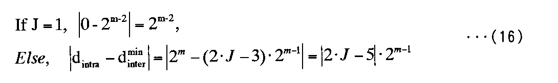
下記式(16)は、Jが1である場合及びそうでない場合に対してそれぞれ隣接アドレス間の距離間の差を求める式を示している。
The following formula (16) shows a formula for obtaining the difference between the distances between adjacent addresses when J is 1 and when it is not.
前記式(16)において、N=2m×Jの関係にあるので、2mをN/Jに置き換えれば、前記式(16)は、下記式(17)のような形態に変わる。 In the formula (16), since N = 2 m × J, the formula (16) is changed to the following formula (17) when 2 m is replaced with N / J.
前記式(17)から隣接アドレス間の距離を最小化するためのJは、常に3で決定され、このときの式(18)は、0.166667Nの値を有することがわかる。 From the equation (17), J for minimizing the distance between adjacent addresses is always determined by 3, and it can be seen that the equation (18) at this time has a value of 0.166667N.
下記表2は、N=384である場合に、mが増加することに従って隣接読出しアドレス間の距離がどのように変化するかを示している。J=3の場合に、隣接アドレス間の距離間の最大差が64で最小化され、同時に、隣接読出しアドレス間の距離の最小値dminも最大化されることを確認することができる。 Table 2 below shows how the distance between adjacent read addresses changes as m increases when N = 384. When J = 3, it can be confirmed that the maximum difference between the distances between adjacent addresses is minimized by 64, and at the same time, the minimum value d min of the distance between adjacent read addresses is also maximized.
以上、インターリーバー入力シーケンスサイズ(interleaver input sequence size)Nが2m またはJに割って余りがない場合を仮定したときに最適のインターリーバーパラメータを決定する方法に対して説明した。 The method for determining the optimal interleaver parameter when it is assumed that there is no remainder when the interleaver input sequence size N is divided by 2 m or J is described above.
次は、Nが2mまたはJに割って余りがある場合を含んだ一般的な場合に対しても、適用可能な最適のインターリーバーパラメータ決定方法に対して説明する。このとき、Nを2mに割ったときの余りをRである仮定する。すなわち、Rは、0より大きく、2mより小さい正の整数である。 Next, an optimal interleaver parameter determination method that can be applied to a general case including the case where N is divided by 2 m or J has a remainder will be described. At this time, it is assumed that the remainder when N is divided by 2 m is R. That is, R is a positive integer greater than 0 and less than 2 m .
図3は、N=408、m=7、J=3、及びR=24である場合の例を通じてR≠0の場合に、P−BROインターリービング動作を説明すると、次のようである。R≠0の場合のインターリービングは、R=0の場合と同様に、行置換え(row permutation)が遂行されたマトリックスの数字(図3の302)を最上方行から各行の左方から右方に読み込んで(図3の303)、これを読出しアドレスとして割り当てることによって行われる。ただ、R≠0の場合に、列の個数はJ+1個になり、J+1番目列はR個の行にのみ数字が記録され、残りの2m−R個の行には、なんの値も記録されない。 FIG. 3 illustrates the P-BRO interleaving operation when R ≠ 0 through the example where N = 408, m = 7, J = 3, and R = 24 as follows. In the case of R ≠ 0, the interleaving is performed in the same manner as in the case of R = 0. The matrix numbers (302 in FIG. 3) subjected to row permutation are changed from the top row to the left to the right of each row. (303 in FIG. 3) and this is assigned as a read address. However, when R ≠ 0, the number of columns is J + 1, and in the J + 1th column, numbers are recorded only in R rows, and any value is recorded in the remaining 2 m -R rows. Not.
すなわち、R≠0の場合に、P−BROチャンネルインターリーバーの読出しアドレスシーケンスは、2m間隔でJまたはJ+1個の数字を順次に配列して作った2m個の行をBROオペレーションによって置換えを遂行して得られたマトリックスで最上方行から各行の左方から右方に読み出して生成される。 That is, when R ≠ 0, the read address sequence of the P-BRO channel interleaver replaces 2 m rows formed by sequentially arranging J or J + 1 numbers at 2 m intervals by BRO operation. In the matrix obtained by performing, it is generated by reading from the left to the right of each row from the top row.
このように、R≠0の場合にも、R=0の場合と同様に、最適のインターリーバーのデザインは、隣接読出しアドレス間の距離の最小値を最大化するとともに、隣接読出しアドレス間の距離を最小化するようにパラメータm及びJを決定することによって達成される。 Thus, in the case of R ≠ 0, as in the case of R = 0, the optimum interleaver design maximizes the minimum value of the distance between adjacent read addresses and the distance between adjacent read addresses. Is achieved by determining the parameters m and J to minimize.
R≠0の場合にも、R=0の場合と同様に、行間距離は、mの関数として2mの値を有する。R=0の場合に、最小行間距離(式(12))がm及びJのみの関数であることに反して、R≠0の場合には、m及びJのみならずRも関数を決定する変数として作用する。 In the case of R ≠ 0, as in the case of R = 0, the inter-line distance has a value of 2 m as a function of m . Contrary to the fact that the minimum inter-line distance (equation (12)) is a function of only m and J when R = 0, when R ≠ 0, not only m and J but also R determines the function. Acts as a variable.
Jの値に従って最小行間距離を計算した結果は、下記式(19)及び式(20)で整理される。式(19)は、J=1の場合の最小行内距離を求めたものであり、式(20)は、J≠1の場合の最小行間距離を求めたものである。
The result of calculating the minimum distance between lines according to the value of J is organized by the following formulas (19) and (20). Expression (19) is a minimum line distance when J = 1, and Expression (20) is a minimum line distance when J ≠ 1.
図4は、m=7及びJ=3の例を通じて前記式(20)がどのように誘導されるかを示している。
図4を参照すると、0≦R<2m−1Rの場合には、行距離が2m−1であり、前方行の終わりの列が満たされない状態にある2つの隣接行の隣接アドレス間の距離が最小行間距離(式(21))になる。一方、2m−1≦R<3・2m−2の場合には、行距離が2m−2であり、前方行の終わりの列が満たされない状態にある2つの隣接行の隣接アドレス間の距離が最小行間距離(式(22))になる。
FIG. 4 shows how equation (20) is derived through the example of m = 7 and J = 3.
Referring to FIG. 4, when 0 ≦ R <2 m−1 R, the row distance is 2 m−1 and the adjacent addresses of two adjacent rows in a state where the end column of the front row is not satisfied Is the minimum distance between lines (formula (21)). On the other hand, when 2 m−1 ≦ R <3 · 2 m−2 , the row distance is 2 m−2 and the adjacent addresses of two adjacent rows in the state where the column at the end of the front row is not satisfied Is the minimum inter-line distance (formula (22)).
![]()
![]()
![]()
![]()
3・2m−2≦R<2mの場合に、行距離が2m−2である2つの隣接行の終わりの列がすべて満たされている状態であるので、このときには、行距離が2m−1である2つの隣接行の隣接アドレス間の距離が最小行内距離(式(23))になる。例えば、Rが0である場合に、参照番号401で示されるように、隣接アドレス間の最小行間距離が192であり、R=64(2m−1)の場合に、参照番号402で示されるように、隣接アドレス間の距離が最小行間距離が288であり、R=96(3・2m−2)の場合に、参照番号403で示されるように、最小行間距離は320である。一方、J=1である場合にも、同一の方式にて式(19)を誘導することができる。
In the case of 3 · 2 m−2 ≦ R <2 m , the end columns of two adjacent rows having a row distance of 2 m−2 are all filled, and at this time, the row distance is 2 The distance between adjacent addresses of two adjacent rows that is m−1 is the minimum in-line distance (formula (23)). For example, when R is 0, as indicated by
![]()
![]()
下記表3は、IS-2000 Specifications, Release Cの6種類のエンコーダーパケット(Encoder Packet;EP)サイズに対してmを増加させつつ、それぞれの場合に該当するJ及びRを計算し、この値を前記式5または式6に代入して行内距離dintra、最小行間距離(式(12))、及び隣接読出しアドレス間の距離の最小値dminを計算した結果を示している。
Table 3 below calculates J and R corresponding to each case while increasing m for the six types of encoder packet (EP) sizes of IS-2000 Specifications, Release C. The result of calculating the in-row distance d intra , the minimum inter-row distance (formula (12)), and the minimum distance d min between adjacent read addresses by substituting into the
前述したように、R=0である場合と同様に、最適のインターリーバーパラメータを選択する基準は、隣接読出しアドレス間の距離の最小値を最大化すると同時に、隣接読出しアドレス間の距離間の差を最大にし、一定に保持すること、すなわち、隣接読出しアドレス間の距離間の差を最小化することである。 As described above, as in the case of R = 0, the criterion for selecting the optimal interleaver parameter is to maximize the minimum distance between adjacent read addresses and at the same time the difference between the distances between adjacent read addresses. To keep it constant, ie to minimize the difference between the distances between adjacent read addresses.
表3において、前記隣接読出しアドレス間の距離の最小値は、八番目列にある値dminであり、この値は、行内距離dintraまたは最小行間距離(式(12))のうち小さい値で決定される。従って、隣接読出しアドレス間の距離の最小値を最大化するパラメータを選択しようとすれば、前記表2において、8番目列にある最大値を有する行を選択しなければならない。しかし、エンコーダーバケット(EP)サイズが2328及び3864である場合に、前記条件を満足する行がそれぞれ3個、2個ずつ複数存在するので、最適のインターリーバーバラメータを選択するために隣接読出しアドレス間の距離間の差を最小化すべき二番目の基準まで適用しなければならない。前記隣接読出しアドレス間の差は、前記表2の七番目列に示されているように、この値を最小化する行をボールド体の下線で表示する。前記二番目基準の妥当性は、前記表2の終わりの列での隣接読出しアドレス間の距離が最小である読出しアドレス対(read address pair)の個数n(dmin)を有する行を比較することによって確認されることができる。 In Table 3, the minimum value of the distance between the adjacent read addresses is the value d min in the eighth column, and this value is a smaller value of the in-line distance d intra or the minimum inter-line distance (formula (12)). It is determined. Therefore, if a parameter that maximizes the minimum value of the distance between adjacent read addresses is selected, the row having the maximum value in the eighth column in Table 2 must be selected. However, when the encoder bucket (EP) size is 2328 and 3864, there are 3 and 2 rows that satisfy the above condition, so that it is necessary to select the optimum interleaver parameter between adjacent read addresses. The difference between the distances must be applied up to the second criterion to be minimized. As shown in the seventh column of Table 2, the difference between the adjacent read addresses is indicated by a bold underline in a row that minimizes this value. The validity of the second criterion is to compare the rows having the number n (d min ) of read address pairs with the smallest distance between adjacent read addresses in the last column of Table 2. Can be confirmed by.
前記表3において、ボールド体の下線で表示された行は、最適のインターリーバーパラメータを選択するための2つの条件を満足しており、2番目条件のみ満足すれば、一番目条件は、自然に満足されることを確認することができる。参考に、前記表2で計算された行内距離dintra及び最小行間距離(式(12))は、すべてP−BROインターリービングによって生成された読出しアドレスを対象にして直接に計算を遂行して得た結果と一致することに留意されたい。前記表2は、インターリーバーサイズNが2mまたはJに割って余りがない場合及び2mまたはJに割って余りがR、すなわち、N個の入力データ列がN=2m×J+R(0≦R<2m)で表現される場合をすべて含んで決定されるインターリーバーパラメータを示す。このとき、ボールド体の下線で表示されたインターリーバーパラメータが各入力データ列の長さに対する最適のインターリーバーパラメータである。これとは異なり、N個の入力データ列がN=2m×(J−1)+R(0≦R<2m)で表現される場合、すなわち、インターリーバーサイズNが2mまたは(J−1)に割って余りがない場合及び2mまたは(J−1)に割って余りがRである場合において、各インターリーバーサイズNに対して決定された最適のインターリーバーパラメータを定めると、下記表4のようである。このように仮定する場合に、前述した説明及び後述する説明で定義されているパラメータ“J”は、“J−1”に置き換えられて定義されることができる。 In Table 3, the line indicated by the bold underline satisfies the two conditions for selecting the optimal interleaver parameter. If only the second condition is satisfied, the first condition is naturally You can confirm that you are satisfied. For reference, the in-line distance d intra and the minimum inter-line distance (equation (12)) calculated in Table 2 are all obtained by directly performing the calculation on the read address generated by P-BRO interleaving. Note that this is consistent with the results. Table 2 shows that when the interleaver size N is not divided by 2 m or J and when there is no remainder when divided by 2 m or J, the remainder is R, that is, N input data strings are N = 2 m × J + R (0 The interleaver parameter determined including all cases expressed by ≦ R <2 m ) is shown. At this time, the interleaver parameter displayed in bold underline is the optimum interleaver parameter for the length of each input data string. In contrast, when N input data strings are expressed by N = 2 m × (J−1) + R (0 ≦ R <2 m ), that is, the interleaver size N is 2 m or (J− When the remainder is divided by 1) and when the remainder is 2 m or (J-1) and the remainder is R, the optimum interleaver parameters determined for each interleaver size N are defined as follows: It is like Table 4. In this case, the parameter “J” defined in the above description and the description below can be defined by replacing “J−1”.
前記説明では、例えば、IS-2000 Release A/Bのチャンネルインターリーバー及びIS-2000 Release Cのサブブロックチャンネルインターリーバーを分析して最適の性能を保証すると予想されるインターリーバーパラメータを選択するための方法を提示している。 In the above description, for example, an IS-2000 Release A / B channel interleaver and an IS-2000 Release C sub-block channel interleaver are analyzed to select an interleaver parameter that is expected to guarantee optimal performance. The method is presented.
前述したように、前記最適のインターリーバーパラメータの決定は、結局、チャンネルインターリーバーによって読出しアドレスを生成するときに、隣接読出しアドレス間の距離を最大化すると同時に、隣接読出しアドレス間の距離を最小化するパラメータを選択することによって達成される。結局、IS-2000 Release Cのサブブロックチャンネルインターリーバーのためのパラメータは、前記表2のボールド体の下線で表示した行に示された値にならなければならない。以上の説明は、IS-2000 Release Cのサブブロックチャンネルインターリーバーを例に挙げて説明したが、本発明に従うインターリーバーが異なる規格のシステムに使用されることができることは、当業者には自明な事実であろう As described above, the determination of the optimal interleaver parameter ultimately maximizes the distance between adjacent read addresses and simultaneously minimizes the distance between adjacent read addresses when the read address is generated by the channel interleaver. This is achieved by selecting the parameters to be performed. Eventually, the parameter for the sub-block channel interleaver of IS-2000 Release C must be the value shown in the line indicated by the underline in bold in Table 2. Although the above description has been given by taking the sub-block channel interleaver of IS-2000 Release C as an example, it is obvious to those skilled in the art that the interleaver according to the present invention can be used in systems of different standards. Will be the fact
図6は、本発明の第1実施例に従う最適のインターリーバーパラメータを決定するための手順を示すフローチャートである。特に、図6は、行内距離dintraと最小行間距離(式(12))との間の差異を算出するための手順である。前述したように、前記2個の値の差異が最小になるようにJを決定しなければ インターリーバーパラメータを最適化できない。すなわち、与えられたインターリーバーサイズNに対して(m,J)を換えつつ式(18)を計算した結果値を利用して最適の(m,J)値を決定する。 FIG. 6 is a flowchart illustrating a procedure for determining optimal interleaver parameters according to the first embodiment of the present invention. In particular, FIG. 6 shows a procedure for calculating the difference between the in-line distance d intra and the minimum inter-line distance (formula (12)). As described above, the interleaver parameter cannot be optimized unless J is determined so that the difference between the two values is minimized. That is, the optimum (m, J) value is determined using the result value obtained by calculating equation (18) while changing (m, J) for a given interleaver size N.
図6を参照すると、まず、ステップ601で、インターリーバーサイズN、パラメータm及びJが与えられると、ステップ603で、前記インターリーバーサイズNから“2m×J”を減算してパラメータRを決定する。そして、ステップ605で、前記J値が‘1’であるか否かを検査する。すなわち、列の個数が1個であるか否かを検査する。前記J値が‘1’であれば、ステップ607に進行し、そうでなければ、ステップ621に進行する。ステップ607で、前記決定された変数Rが‘0’であるか否かを検査する。すなわち、インターリーバーサイズNが2mの整数倍であるか否かを検査する。一方、前記パラメータRが‘0’であれば、ステップ609に進行して行内距離を示すパラメータdintraに‘0’値を貯蔵し、そうでなければ、ステップ617に進行して前記パラメータdintraに‘2m’の値を貯蔵する。
Referring to FIG. 6, when an interleaver size N and parameters m and J are given in
前記行内距離を示すパラメータdintraを決定した後に、ステップ611で、Rが‘3×2m−2’より小さいか否かを検査する。Rが前記‘3×2m−2’より小さければ、ステップ613に進行して最小行間距離を示す式(12)は2m−2に設定され、Rが前記‘3×2m−2’より大きいかまたは同じであれば、ステップ619に進行して式(12)は2m−1に設定される。式(12)を決定した後に、ステップ615に進行して前記決定されたdintraと前記式(12)との間の差異を計算した後に終了する。
After determining the parameter d intra indicating the in-line distance, it is checked in
一方、ステップ605で、Jが‘1’ではない場合に、ステップ621に進行して行内距離を示すdintraは‘2m’に設定され、ステップ623で、Rが‘2m−1’より小さいか否かを検査する。Rが‘2m−1’より小さければ、ステップ625に進行して前記最小行間距離を示す式(12)は‘(2J−3)×2m−1’に設定された後に、ステップ615に進行する。一方、Rが前記‘2m−1’より大きいかまたは同じであれば、ステップ627に進行してRが‘3×2m−2’より小さいか否かを検査する。Rが‘3×2m−2’より小さければ、ステップ629に進行して、前記最小行間距離を示す式(12)は‘(4J−3)×2m−2’に設定され、そうでなければ、ステップ631に進行して式(12)は‘(2J−1)×2m−1’に設定された後に、ステップ615に進行する。
On the other hand, if J is not '1' in
前述したように、与えられたNに対する最適のインターリーバーパラメータは(m,J)を換えつつ、式(18)を計算する試みを反復することによって得られることができる。しかし、最適のインターリーバーパラメータで選択されるJの値が1、2、3のうちの1つであることを利用すると、このような試みを遂行せず、与えられたNに対する最適のインターリーバーパラメータJを簡単に計算する論理式を誘導することができる。
論理式の誘導過程は省略し、誘導された論理式をまとめると、下記式(24)のようである。
As described above, the optimal interleaver parameter for a given N can be obtained by repeating the attempt to calculate equation (18), changing (m, J). However, using the fact that the value of J selected by the optimal interleaver parameter is one of 1, 2, 3 does not perform such an attempt and the optimal interleaver for a given N A logical expression that simply calculates the parameter J can be derived.
The induction process of the logical expression is omitted, and the derived logical expressions are summarized as the following expression (24).
前記式(24)を利用して得たJの最適値(optimal value)からmの最適値は、下記式(25)によって計算されることができる。 The optimum value of m can be calculated by the following equation (25) from the optimum value of J obtained using the equation (24).
結局、最適のインターリーバーパラメータを簡単な論理式を利用して求める過程は、次のように要約され、図7に示すようである。
1.与えられたNに対して式7を利用してJの最適値を得る。
2.N及びJを式(25)に代入してmを計算する。
Eventually, the process of obtaining the optimal interleaver parameter using a simple logical expression is summarized as follows and is shown in FIG.
1. The optimal value of J is obtained using Equation 7 for a given N.
2. Substitute N and J into equation (25) to calculate m.
図7は、本発明の他の実施例による最適のインターリーバーパラメータを決定するための手順を示すフローチャートである。
図7を参照すると、ステップ701で、まず与えられたインターリーバーサイズNをもって式(26) を計算して変数値αが決定され、前記Nで式(27)を計算して変数値βが決定される。そして、ステップ703で、前記変数値αが第1基準値0.5849625より小さいか否かを検査する。前記変数値αが第1基準値より小さければ、ステップ705に進行して前記インターリーバーサイズNの値が前記変数値βより小さいか否かを検査する。前記インターリーバーサイズNの値が前記変数値βより大きいかまたは同じであれば、ステップ707に進行し、そうでなければ、ステップ713に進行して列の個数を示すJを‘3’に決定する。
FIG. 7 is a flowchart illustrating a procedure for determining optimal interleaver parameters according to another embodiment of the present invention.
Referring to FIG. 7, in
一方、ステップ707で、前記インターリーバーサイズNの値が‘(3/2)×β’より小さいか否かを検査する。前記インターリーバーサイズNの値が前記‘(3/2)×β’より小さければ、ステップ711に進行して前記Jを‘2’に決定し、そうでなければ、ステップ709に進行して前記Jを‘1’に決定する。
On the other hand, in
ステップ703で、前記変数値αが前記第1基準値より大きいかまたは同じであれば、ステップ717に進行して、前記インターリーバーサイズNの値が前記‘(3/2)×β’より小さいか否かを検査する。前記インターリーバーサイズNの値が前記‘(3/2)×β’より小さければ、ステップ721に進行して前記Jを‘2’に決定し、そうでなければ、ステップ719に進行して、前記インターリーバーサイズNの値が‘(7/4)×β’より小さいか否かを検査する。前記インターリーバーサイズNの値が前記‘(7/4)×β’より小さければ、ステップ723に進行して前記Jを‘3’に決定し、そうでなければ、ステップ725に進行してJを‘1’に決定する。
In
前述したように、Nを利用して論理式によってm及びJの最適値(optimal value)を簡単に計算することができ、このように計算されたm及びJは、前記表2に示すように、(m,J)を換える数回の試みを通じて得られたm,Jと正確に一致する値を有する。また、これは、Nの値に従う最適のパラメータm及びJを貯蔵しておく必要性がなくなることを意味する。 As described above, the optimal values of m and J can be easily calculated using a logical expression using N, and m and J calculated in this way are as shown in Table 2 above. , (M, J) with values that exactly match m, J obtained through several attempts. This also means that there is no need to store optimal parameters m and J according to the value of N.
例えば、N=2328の場合に、図7に示す手順または式(25)乃至式(2)を利用してm及びJの最適値を計算する過程を説明すると、次のようである。
参考に、前記式(24)の誘導過程を説明すると、次のようである。 For reference, the induction process of the equation (24) will be described as follows.
図6、式(19)及び式(20)からそれぞれの場合に対する式(18)は、下記のように記述される。 From FIG. 6, Equation (19) and Equation (20), Equation (18) for each case is described as follows.
このとき、N=2m・J+Rであり、0≦R<2m、J・2m≦N<(J+1)・2mが成立し、Jに割ってログベースが2であるlogを取ると、
式(29)が成立するので、mは、式(30)のように表示されることができる。式(30)を利用すると、特定のJに対して、A及びBのすべての場合をNの関数で表示することができる。
At this time, N = 2 m · J + R, and 0 ≦ R <2 m , J · 2 m ≦ N <(J + 1) · 2 m is established, and if log that the log base is 2 divided by J is taken ,
Since equation (29) holds, m can be expressed as in equation (30). Using equation (30), all cases of A and B can be expressed as a function of N for a particular J.
Jが4またはそれ以上であるときには、いずれの場合にも、J=1、2、または3である場合の式(18)より小さい値を有することができないので考慮する必要がない。
A’−1、A’−2、A’−3、B”−1、B”−2、B”−3、B”’−1’、B”’−2’、及びB”’−3’の場合をすべて考慮して、式(18)を最小化する場合を選択して式7を得ることができ、同様に、A’−1、A’−2、A’−3、B”−1、B”−2、B”−3、B”’−1”、B”’−2”、及びB”’−3”の場合をすべて考慮して、式(18)を最小化する場合を選択して式(25)を得ることができる。
When J is 4 or more, there is no need to consider in any case because it cannot have a value smaller than equation (18) when J = 1, 2, or 3.
A'-1, A'-2, A'-3, B "-1, B" -2, B "-3, B"'-1', B "'-2', and B"'-3 In consideration of all cases of ', the case of minimizing the equation (18) can be selected to obtain the equation 7, and similarly, A'-1, A'-2, A'-3, B " −1, B ″ −2, B ″ −3, B ″ ′ − 1 ″, B ″ ′ − 2 ″, and B ″ ′-3 ″ are all considered and Equation (18) is minimized. The case can be selected to obtain equation (25).
以上、本発明を具体的な実施形態を参照して詳細に説明してきたが、本発明の範囲は前述の実施形態によって限られるべきではなく、本発明の範囲内で様々な変形が可能であるということは、当該技術分野における通常の知識を持つ者には明らかである。 Although the present invention has been described in detail with reference to specific embodiments, the scope of the present invention should not be limited by the above-described embodiments, and various modifications can be made within the scope of the present invention. This is clear to those with ordinary knowledge in the art.
511 アドレス生成部
512 インターリーバメモリ
513 カウンタ
511
Claims (5)
N個の入力データ列を2m個の行及び(J−1)個の列のマトリックス構造、及びJ番目列でR(ここで、0≦R<2m)個の行になるように列の順序で配列する過程と、
前記配列された行のデータを部分ビット逆相順(P−BRO)インターリービングし、前記インターリービングされたデータを行の順序で読み出すためのアドレスを生成する過程と、
前記生成された読出しアドレスの各行に対して隣接する列を指示するアドレス間の第1最小距離を算出する過程と、
前記生成された読出しアドレスの隣接する2個の行に対して一番目行の最終列を指示するアドレスと二番目行の最初列を指示するアドレスとの間の第2最小距離を算出する過程と、
前記第1最小距離と前記第2最小距離との間の差異を最小にするパラメータm及びJが求められるときまで、前記配列過程、前記P−BROインターリービング過程、前記第1最小距離算出過程及び前記第2最小距離算出過程を反復する過程と、を備えることを特徴とするインターリービングパラメータ決定方法。 In a method for determining parameters for use in an interleaver in a communication system,
N input data columns are arranged in a matrix structure of 2 m rows and (J−1) columns, and the Jth column is R (where 0 ≦ R <2 m ) rows. The process of arranging in the order of
Performing partial bit reverse phase (P-BRO) interleaving on the arranged rows of data and generating an address for reading the interleaved data in the row order;
Calculating a first minimum distance between addresses indicating adjacent columns for each row of the generated read address;
Calculating a second minimum distance between an address indicating the last column of the first row and an address indicating the first column of the second row for two adjacent rows of the generated read address; ,
Until the parameters m and J that minimize the difference between the first minimum distance and the second minimum distance are determined, the arranging process, the P-BRO interleaving process, the first minimum distance calculating process, and And a step of repeating the second minimum distance calculation step.
N個の入力データ列を2m個の行及び(J−1)個の列のマトリックス構造、及び最終列でR(0≦R<2m)個の行になるように列の順序で配列する過程と、
前記配列された行のデータを部分ビット逆相順(P−BRO)インターリービングし、前記インターリービングされたデータを行の順序で読み出すためのアドレスを生成する過程と、
前記生成された読出しアドレスの各行に対して隣接する列を指示するアドレス間の第1最小距離を算出する過程と、
前記生成された読出しアドレスの隣接する2個の行に対して一番目行の最終列を指示するアドレスと二番目行の最初列を指示するアドレスとの間の第2最小距離を算出する過程と、
前記第1最小距離及び前記第2最小距離のうちの1つを最大にするパラメータm及びJが求められるときまで、前記配列過程、前記P−BROインターリービング過程、前記第1最小距離算出過程及び前記第2最小距離算出過程を反復する過程と、を備えることを特徴とするインターリービングパラメータ決定方法。 In a method for determining parameters for use in an interleaver in a communication system,
The N 2 m pieces of input data string of the row and (J-1) pieces of the matrix structure of rows and the last column in the R (0 ≦ R <2 m ) pieces consisting of a row as arranged in the order of the columns The process of
Performing partial bit reverse phase (P-BRO) interleaving on the arranged rows of data and generating an address for reading the interleaved data in the row order;
Calculating a first minimum distance between addresses indicating adjacent columns for each row of the generated read address;
Calculating a second minimum distance between an address indicating the last column of the first row and an address indicating the first column of the second row for two adjacent rows of the generated read address; ,
Until the parameters m and J that maximize one of the first minimum distance and the second minimum distance are determined, the arranging process, the P-BRO interleaving process, the first minimum distance calculating process, and And a step of repeating the second minimum distance calculation step.
Applications Claiming Priority (3)
| Application Number | Priority Date | Filing Date | Title |
|---|---|---|---|
| KR10-2002-0006890 | 2002-02-06 | ||
| KR20020006890 | 2002-02-06 | ||
| PCT/KR2003/000261 WO2003067766A1 (en) | 2002-02-06 | 2003-02-06 | Interleaver and interleaving method in a communication system |
Related Child Applications (1)
| Application Number | Title | Priority Date | Filing Date |
|---|---|---|---|
| JP2004214876A Division JP3878627B2 (en) | 2002-02-06 | 2004-07-22 | Interleaver and interleaving method in communication system |
Publications (4)
| Publication Number | Publication Date |
|---|---|
| JP2005517339A JP2005517339A (en) | 2005-06-09 |
| JP2005517339A6 JP2005517339A6 (en) | 2005-08-11 |
| JP2005517339A5 JP2005517339A5 (en) | 2005-12-22 |
| JP3880964B2 true JP3880964B2 (en) | 2007-02-14 |
Family
ID=27607079
Family Applications (2)
| Application Number | Title | Priority Date | Filing Date |
|---|---|---|---|
| JP2003566989A Expired - Lifetime JP3880964B2 (en) | 2002-02-06 | 2003-02-06 | Interleaver and interleaving method in communication system |
| JP2004214876A Expired - Lifetime JP3878627B2 (en) | 2002-02-06 | 2004-07-22 | Interleaver and interleaving method in communication system |
Family Applications After (1)
| Application Number | Title | Priority Date | Filing Date |
|---|---|---|---|
| JP2004214876A Expired - Lifetime JP3878627B2 (en) | 2002-02-06 | 2004-07-22 | Interleaver and interleaving method in communication system |
Country Status (10)
| Country | Link |
|---|---|
| US (2) | US7263637B2 (en) |
| EP (2) | EP1335497A3 (en) |
| JP (2) | JP3880964B2 (en) |
| KR (1) | KR100480264B1 (en) |
| CN (2) | CN100568745C (en) |
| AU (1) | AU2003208028B2 (en) |
| BR (1) | BR0302968A (en) |
| CA (1) | CA2443453C (en) |
| RU (2) | RU2261529C2 (en) |
| WO (1) | WO2003067766A1 (en) |
Families Citing this family (24)
| Publication number | Priority date | Publication date | Assignee | Title |
|---|---|---|---|---|
| BR0302968A (en) * | 2002-02-06 | 2004-07-13 | Samsung Electronics Co Ltd | Interleaver and interleaving method in a communication system |
| US8077743B2 (en) * | 2003-11-18 | 2011-12-13 | Qualcomm Incorporated | Method and apparatus for offset interleaving of vocoder frames |
| US7343530B2 (en) * | 2004-02-10 | 2008-03-11 | Samsung Electronics Co., Ltd. | Turbo decoder and turbo interleaver |
| US7392464B1 (en) * | 2004-04-30 | 2008-06-24 | Marvell International Ltd. | Universal parity encoder |
| GB2419788B (en) * | 2004-11-01 | 2007-10-31 | Toshiba Res Europ Ltd | Interleaver and de-interleaver systems |
| KR101131323B1 (en) * | 2004-11-30 | 2012-04-04 | 삼성전자주식회사 | Apparatus and method for channel interleaving in a wireless communication system |
| US7542410B2 (en) * | 2004-12-06 | 2009-06-02 | Intel Corporation | Interleaver and associated methods |
| US7543197B2 (en) | 2004-12-22 | 2009-06-02 | Qualcomm Incorporated | Pruned bit-reversal interleaver |
| US7552377B1 (en) * | 2005-02-10 | 2009-06-23 | Xilinx, Inc. | Method of and circuit for interleaving data in a data coder |
| US7797615B2 (en) * | 2005-07-07 | 2010-09-14 | Acer Incorporated | Utilizing variable-length inputs in an inter-sequence permutation turbo code system |
| US20070011557A1 (en) * | 2005-07-07 | 2007-01-11 | Highdimension Ltd. | Inter-sequence permutation turbo code system and operation methods thereof |
| US7856579B2 (en) | 2006-04-28 | 2010-12-21 | Industrial Technology Research Institute | Network for permutation or de-permutation utilized by channel coding algorithm |
| US8185785B2 (en) * | 2006-11-28 | 2012-05-22 | At&T Intellectual Property I, L.P. | Broadcasting of digital video to mobile terminals |
| KR101435830B1 (en) * | 2007-06-20 | 2014-08-29 | 엘지전자 주식회사 | Method of performing interleaving |
| CN101159510B (en) * | 2007-11-16 | 2011-09-28 | 海能达通信股份有限公司 | Method for improving dependability of information bit transmission |
| CN101910856B (en) | 2008-01-29 | 2014-06-18 | 立维腾制造有限公司 | Self testing fault circuit interrupter apparatus and method |
| US10022468B2 (en) * | 2009-02-02 | 2018-07-17 | Kimberly-Clark Worldwide, Inc. | Absorbent articles containing a multifunctional gel |
| US8638244B2 (en) | 2009-08-31 | 2014-01-28 | Freescale Semiconductor, Inc. | Encoding module, apparatus and method for determining a position of a data bit within an interleaved data stream |
| GB2523363B (en) * | 2014-02-21 | 2017-06-28 | Samsung Electronics Co Ltd | Bit interleaver and bit de-interleaver |
| EP3113387B1 (en) * | 2014-03-21 | 2019-05-22 | Huawei Technologies Co., Ltd. | Polar code rate-matching method and rate-matching device |
| WO2015143593A1 (en) | 2014-03-24 | 2015-10-01 | 华为技术有限公司 | Rate matching method and rate matching apparatus for polar codes |
| US9759758B2 (en) | 2014-04-25 | 2017-09-12 | Leviton Manufacturing Co., Inc. | Ground fault detector |
| KR20190033588A (en) | 2017-02-10 | 2019-03-29 | 텔레폰악티에볼라겟엘엠에릭슨(펍) | System and method for rate matching for polar codes |
| CN113839738B (en) * | 2020-06-23 | 2023-06-20 | 中国科学院上海高等研究院 | Cross-reading block interleaving processing method and system |
Family Cites Families (14)
| Publication number | Priority date | Publication date | Assignee | Title |
|---|---|---|---|---|
| US5996104A (en) * | 1996-09-13 | 1999-11-30 | Herzberg; Hanan | System for coding system |
| DE19831340C1 (en) | 1998-07-13 | 2000-03-02 | Siemens Ag | Method and arrangement for calibrating a laser processing machine for processing workpieces |
| JP3453122B2 (en) * | 1998-08-17 | 2003-10-06 | ヒューズ・エレクトロニクス・コーポレーション | Turbo code interleaver close to optimum performance |
| US6304991B1 (en) * | 1998-12-04 | 2001-10-16 | Qualcomm Incorporated | Turbo code interleaver using linear congruential sequence |
| US6871303B2 (en) * | 1998-12-04 | 2005-03-22 | Qualcomm Incorporated | Random-access multi-directional CDMA2000 turbo code interleaver |
| KR100346170B1 (en) * | 1998-12-21 | 2002-11-30 | 삼성전자 주식회사 | Interleaving / deinterleaving apparatus and method of communication system |
| KR100350459B1 (en) * | 1998-12-26 | 2002-12-26 | 삼성전자 주식회사 | Interleaving / deinterleaving apparatus and method of communication system |
| US6463556B1 (en) | 1999-01-04 | 2002-10-08 | Motorola, Inc. | Method and apparatus for interleaving in a communication system |
| EP1139572A4 (en) | 1999-10-07 | 2005-04-13 | Matsushita Electric Ind Co Ltd | Interleave address generating device and interleave address generating method |
| KR100450948B1 (en) * | 2001-07-12 | 2004-10-02 | 삼성전자주식회사 | Apparatus and method for determining modulation scheme in communication system |
| KR100800807B1 (en) * | 2001-11-20 | 2008-02-01 | 삼성전자주식회사 | Method and apparatus for determining modulation scheme of retransmission in communication system |
| KR100860660B1 (en) | 2002-01-09 | 2008-09-26 | 삼성전자주식회사 | Interleaving apparatus and method in communication system |
| BR0302968A (en) * | 2002-02-06 | 2004-07-13 | Samsung Electronics Co Ltd | Interleaver and interleaving method in a communication system |
| KR101131323B1 (en) * | 2004-11-30 | 2012-04-04 | 삼성전자주식회사 | Apparatus and method for channel interleaving in a wireless communication system |
-
2003
- 2003-02-06 BR BR0302968-9A patent/BR0302968A/en not_active Application Discontinuation
- 2003-02-06 US US10/359,162 patent/US7263637B2/en active Active
- 2003-02-06 AU AU2003208028A patent/AU2003208028B2/en not_active Expired
- 2003-02-06 EP EP03002557A patent/EP1335497A3/en not_active Ceased
- 2003-02-06 CN CNB2004100015003A patent/CN100568745C/en not_active Expired - Lifetime
- 2003-02-06 EP EP04002547A patent/EP1420519A1/en not_active Ceased
- 2003-02-06 JP JP2003566989A patent/JP3880964B2/en not_active Expired - Lifetime
- 2003-02-06 CA CA002443453A patent/CA2443453C/en not_active Expired - Lifetime
- 2003-02-06 RU RU2003136830/09A patent/RU2261529C2/en active
- 2003-02-06 WO PCT/KR2003/000261 patent/WO2003067766A1/en active IP Right Grant
- 2003-02-06 RU RU2003129507/09A patent/RU2255419C2/en active
- 2003-02-06 KR KR10-2003-0007606A patent/KR100480264B1/en not_active IP Right Cessation
- 2003-02-06 CN CNB038002337A patent/CN1324811C/en not_active Expired - Lifetime
- 2003-12-02 US US10/724,877 patent/US7137044B2/en active Active
-
2004
- 2004-07-22 JP JP2004214876A patent/JP3878627B2/en not_active Expired - Lifetime
Also Published As
| Publication number | Publication date |
|---|---|
| CN1324811C (en) | 2007-07-04 |
| RU2003129507A (en) | 2005-04-10 |
| RU2003136830A (en) | 2005-05-10 |
| KR100480264B1 (en) | 2005-04-07 |
| EP1420519A1 (en) | 2004-05-19 |
| JP2005517339A (en) | 2005-06-09 |
| RU2255419C2 (en) | 2005-06-27 |
| RU2261529C2 (en) | 2005-09-27 |
| CN1520045A (en) | 2004-08-11 |
| US20040170232A1 (en) | 2004-09-02 |
| CA2443453C (en) | 2008-01-15 |
| KR20030067557A (en) | 2003-08-14 |
| EP1335497A3 (en) | 2004-05-19 |
| AU2003208028B2 (en) | 2005-07-07 |
| BR0302968A (en) | 2004-07-13 |
| CN100568745C (en) | 2009-12-09 |
| CA2443453A1 (en) | 2003-08-14 |
| JP3878627B2 (en) | 2007-02-07 |
| US7137044B2 (en) | 2006-11-14 |
| AU2003208028A1 (en) | 2003-09-02 |
| US20030167436A1 (en) | 2003-09-04 |
| WO2003067766A1 (en) | 2003-08-14 |
| EP1335497A2 (en) | 2003-08-13 |
| JP2005012825A (en) | 2005-01-13 |
| CN1507694A (en) | 2004-06-23 |
| US7263637B2 (en) | 2007-08-28 |
Similar Documents
| Publication | Publication Date | Title |
|---|---|---|
| JP3880964B2 (en) | Interleaver and interleaving method in communication system | |
| JP2005517339A6 (en) | Interleaver and interleaving method in communication system | |
| JP3549788B2 (en) | Multi-stage encoding method, multi-stage decoding method, multi-stage encoding device, multi-stage decoding device, and information transmission system using these | |
| TWI493337B (en) | Method of accessing a memory and computing device | |
| US6324226B1 (en) | Viterbi decoder | |
| JP3574405B2 (en) | Two-dimensional interleaving apparatus and method | |
| EP1733477B1 (en) | Sub-block interleaving and de-interleaving for multidimensional product block codes | |
| KR20020048975A (en) | High-speed acs unit for a viterbi decoder | |
| JP3796250B2 (en) | Deinterleaving apparatus for digital communication system and deinterleaving method thereof | |
| US7861146B2 (en) | Viterbi decoding apparatus and Viterbi decoding method | |
| KR100499467B1 (en) | Block interleaving method, and apparatus for the same | |
| US6940929B2 (en) | Low-latency high-speed trellis decoder | |
| KR20030005267A (en) | Method and apparatus for efficiently reading and storing state metrics in memory for high-speed acs viterbi decoder implementations | |
| JP2009246474A (en) | Turbo decoder | |
| US20100318873A1 (en) | Tree Decoding Method For Decoding Linear Block Codes | |
| AU2003268814B2 (en) | Interleaver and interleaving method in a communication system | |
| KR100828243B1 (en) | Turbo decoder using single address generator and Method for assigning memory address using the same | |
| KR101279204B1 (en) | Apparatus and method for inner interleaving of turbo encoder | |
| Bai et al. | Efficient list decoding for parallel concatenated convolutional codes | |
| JP2009231979A (en) | Memory reduction rate matching processor for broadcast channel | |
| JP2000232378A (en) | Interleaving device and interleaving method | |
| KR20000071582A (en) | 2-dimensional interleaving apparatus and method | |
| JP2004120791A (en) | Viterbi decoder |
Legal Events
| Date | Code | Title | Description |
|---|---|---|---|
| A977 | Report on retrieval |
Free format text: JAPANESE INTERMEDIATE CODE: A971007 Effective date: 20061010 |
|
| TRDD | Decision of grant or rejection written | ||
| A01 | Written decision to grant a patent or to grant a registration (utility model) |
Free format text: JAPANESE INTERMEDIATE CODE: A01 Effective date: 20061017 |
|
| A61 | First payment of annual fees (during grant procedure) |
Free format text: JAPANESE INTERMEDIATE CODE: A61 Effective date: 20061108 |
|
| R150 | Certificate of patent or registration of utility model |
Ref document number: 3880964 Country of ref document: JP Free format text: JAPANESE INTERMEDIATE CODE: R150 Free format text: JAPANESE INTERMEDIATE CODE: R150 |
|
| FPAY | Renewal fee payment (event date is renewal date of database) |
Free format text: PAYMENT UNTIL: 20091117 Year of fee payment: 3 |
|
| FPAY | Renewal fee payment (event date is renewal date of database) |
Free format text: PAYMENT UNTIL: 20101117 Year of fee payment: 4 |
|
| R250 | Receipt of annual fees |
Free format text: JAPANESE INTERMEDIATE CODE: R250 |
|
| FPAY | Renewal fee payment (event date is renewal date of database) |
Free format text: PAYMENT UNTIL: 20111117 Year of fee payment: 5 |
|
| R250 | Receipt of annual fees |
Free format text: JAPANESE INTERMEDIATE CODE: R250 |
|
| FPAY | Renewal fee payment (event date is renewal date of database) |
Free format text: PAYMENT UNTIL: 20111117 Year of fee payment: 5 |
|
| FPAY | Renewal fee payment (event date is renewal date of database) |
Free format text: PAYMENT UNTIL: 20121117 Year of fee payment: 6 |
|
| R250 | Receipt of annual fees |
Free format text: JAPANESE INTERMEDIATE CODE: R250 |
|
| FPAY | Renewal fee payment (event date is renewal date of database) |
Free format text: PAYMENT UNTIL: 20131117 Year of fee payment: 7 |
|
| R250 | Receipt of annual fees |
Free format text: JAPANESE INTERMEDIATE CODE: R250 |
|
| R250 | Receipt of annual fees |
Free format text: JAPANESE INTERMEDIATE CODE: R250 |
|
| R250 | Receipt of annual fees |
Free format text: JAPANESE INTERMEDIATE CODE: R250 |
|
| R250 | Receipt of annual fees |
Free format text: JAPANESE INTERMEDIATE CODE: R250 |
|
| R250 | Receipt of annual fees |
Free format text: JAPANESE INTERMEDIATE CODE: R250 |
|
| R250 | Receipt of annual fees |
Free format text: JAPANESE INTERMEDIATE CODE: R250 |
|
| R250 | Receipt of annual fees |
Free format text: JAPANESE INTERMEDIATE CODE: R250 |
|
| R250 | Receipt of annual fees |
Free format text: JAPANESE INTERMEDIATE CODE: R250 |
|
| R250 | Receipt of annual fees |
Free format text: JAPANESE INTERMEDIATE CODE: R250 |
|
| R250 | Receipt of annual fees |
Free format text: JAPANESE INTERMEDIATE CODE: R250 |
|
| R250 | Receipt of annual fees |
Free format text: JAPANESE INTERMEDIATE CODE: R250 |
|
| EXPY | Cancellation because of completion of term |