JP3879397B2 - Keyless entry system - Google Patents
Keyless entry system Download PDFInfo
- Publication number
- JP3879397B2 JP3879397B2 JP2000387526A JP2000387526A JP3879397B2 JP 3879397 B2 JP3879397 B2 JP 3879397B2 JP 2000387526 A JP2000387526 A JP 2000387526A JP 2000387526 A JP2000387526 A JP 2000387526A JP 3879397 B2 JP3879397 B2 JP 3879397B2
- Authority
- JP
- Japan
- Prior art keywords
- door
- driver
- seat
- lock
- vehicle
- Prior art date
- Legal status (The legal status is an assumption and is not a legal conclusion. Google has not performed a legal analysis and makes no representation as to the accuracy of the status listed.)
- Expired - Lifetime
Links
Images


Landscapes
- Lock And Its Accessories (AREA)
Description
【0001】
【発明の属する技術分野】
本発明は、車両のキーレスエントリーシステムに関する。
【0002】
【従来の技術】
従来、自動車の乗降車時に、携帯可能な送信機のボタンを押すことにより送信機から信号を送信し、車両ドアに設けられた受信機によってその信号を受信してドアのロック・アンロックを行う、いわゆるキーレスエントリーシステムや、ドライバがカードキーを所持し、車両に近づくことにより、あるいはドアに設けられたボタンを押すことによって、カードキーと車両側受信機が交信してドアのロック・アンロックを行うシステムが知られている。
【0003】
ところが、これらのキーレスエントリーシステムにおいては、乗降車時にキーをドアロック・アンロック用キーシリンダに差し込むことなくドアのロック・アンロックが行われるため、全席のドアをロックする集中ドアロックによって全席ドアをロックした後、ドライバが車両から降車するためにドライバ席のドアロックノブをアンロックし、降車した後にドライバ席のロックノブによってロックしてドアノブを引いたまま閉める、いわゆる「投げドア」を行った場合、送信機又はカードキーを車室内に閉じ込めてしまう恐れがあった。
【0004】
このようなキー閉じ込めを防止するための技術として、従来、特許第2921170号公報に記載されたキーレスエントリーシステムが知られている。このキーレスエントリーシステムにおいては、運転席ドアが開扉され、かつ、キーがイグニッションキーシリンダに挿入されているか、若しくは送信機あるいは電子キーが車室内に存在していることを検知した場合に、ドアがロックされたことが検知されるとそのドアを強制的にアンロックすることにより、上述したシチュエーションでのキー閉じ込めを防止する技術である。
【0005】
【発明が解決しようとする課題】
しかしながら、上記の従来技術においては、キー、送信機あるいは電子キーが車室内に存在している状態で、運転席ドアが開扉された後に、ドアがロックされたことを検出した場合に、強制的にアンロックするようにしていたので、車両のドアに、ドアのロック・アンロック状態を検知するためのロック状態検出スイッチを設けることが必要となり、コストアップを招く問題点があった。
【0006】
本発明はこのような従来の問題点に鑑みてなされたものであって、コストアップすることなくキー閉じ込めをほぼ確実に防止することができるキーレスエントリーシステムを提供することを目的とする。
【0007】
【課題を解決するための手段】
請求項1の発明は、ドアの開閉状態を検出するドア開閉状態検出手段と、各席ドアそれぞれをロック及びアンロックする各席ドアロックノブと、全席又は運転席以外の全席(以下、「全席」と総称する)のドアのロック・アンロックを同時に行う際に操作される集中ドアロックスイッチと、前記集中ドアロックスイッチからの信号を受けて、全席のドアのロック・アンロックを制御するロックコントローラとを備え、携帯可能な通信機から送信される指令信号に応答してドアのロック・アンロックを行うキーレスエントリーシステムにおいて、車室内に前記通信機が存在することを検知する通信機存在検知手段と、ドライバが車両に乗車してから運転を中止するまでの間の前記集中ドアロックスイッチの操作による全席のドアのロック・アンロック状態を、前記操作が行われる毎に更新しながら記憶するメモリとを備え、前記ロックコントローラが、ドライバが車両の運転を中止してからの運転席ドアの開放が前記ドア開閉状態検出手段により検出されたときに、前記メモリに記憶されているロック・アンロック状態がロック状態を示すものであり、且つ、前記通信機存在検知手段により車室内に前記通信機が存在することが検知されたことを条件として、少なくとも1つのドアをアンロックする機能を備えたことを特徴とするものである。
【0008】
請求項2の発明は、携帯可能な通信機から送信される指令信号に応答してドアのロック・アンロックを行うキーレスエントリーシステムにおける前記通信機の車両内への閉じ込めを防止する通信機閉じ込め防止方法であって、ドライバが車両に乗車してから運転を中止するまでの間の集中ドアロックスイッチの操作による全席のドアのロック・アンロック状態を、前記操作が行われる毎に更新しながらメモリに記憶させておき、ドライバが車両の運転を中止してからの運転席ドアの開放が検出されたときに、前記メモリに記憶されているロック・アンロック状態がロック状態を示すものであり、且つ、車室内に前記通信機が存在することが検知されたことを条件として、少なくとも1つのドアをアンロックすることを特徴とするものである。
【0009】
本発明では、ドライバが車両の運転を中止してからの運転席ドアの開放が検出されたときに、ドライバが車両に乗車してから運転を中止するまでの間に集中ドアロックスイッチを操作して全席又は運転席以外の全席のドアをロック状態としたことがメモリに記憶されており、且つ、ドアロック・アンロック用の通信機が車室内に存在することが検知されたことを条件として、ロックコントローラが、少なくとも1つのドアをアンロックする。
【0010】
これにより、ドアロック・アンロック用の通信機が車室内に残されたまま投げドアされるような状況では、少なくとも1つのドアがいったんアンロックされるので、キーレス操作用の通信機を車室内へ閉じ込めるのを防止することができ、しかもドアのロック・アンロック状態検出用のロック状態検出手段をドアに設ける必要がなくてコストアップを抑制することができる。
【0012】
【発明の実施の形態】
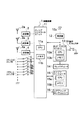
以下、本発明の実施の形態を図に基づいて詳説する。図1は本発明の第1の実施の形態のキーレスエントリーシステムにおける車載装置1の構成を示している。図2はキーレスエントリーシステムの携帯用電子キー20の構成を示している。図3はイグニッションノブを示している。
【0013】
この実施の形態のキーレスエントリーシステムにおける車載装置1は、電子キー20と無線通信を行うための送信機2,3,4、受信機12を備えており、送信機2は、例えば運転席シート又は運転席天井部に設置され、アンテナ2aから、例えば「エンジン始動用ID要求信号」、「ID要求信号」を受信してドライバが携帯する電子キー20へ送信する。
【0014】
送信機3は、図4に示すように運転席ドア40のドアアウトサイドハンドル41の周辺に設置され、ドアアンテナ3aから、例えば「ドアロック信号」、「ドアアンロック信号」を運転席の近くの乗員が携帯する電子キー20へ送信する。なお、運転席ドアアンテナ3aの指向性を調整することによって、ドアアンテナ3aを介して車載装置1と携帯用電子キー20との間で無線通信が可能な領域を、運転席ドア40付近の車外のみの領域42とする。この通信可能領域42は、運転席ドア40付近の、乗員が電子キー20によってドアロックスイッチ9aを操作してドアロックを行う範囲をカバーできる程度の狭い領域でよい。
【0015】
同様に、送信機4は助手席ドア43のドアアウトサイドハンドル周辺に設置され、ドアアンテナ4aから「ドアロック信号」、「ドアアンロック信号」を助手席ドア近くの乗員が携帯する電子キー20へ送信する。なお、ドアアンテナ4aの指向性を調整することによって、ドアアンテナ4aを介して車載装置1と電子キー20との間で無線通信が可能な領域を、助手席ドア43付近の車外のみの領域44とする。この通信可能領域44は、助手席ドア43付近の、乗員が電子キー20によってドアロックスイッチ9bを操作してドアロックを行う範囲をカバーできる程度の狭い領域でよい。
【0016】
車載装置1におけるパッシブコントロールユニット11は、CPU11aと不揮発性メモリ11bを備え、送信機2,3,4、受信機12を介して電子キー20と無線通信を行い、イグニッションスイッチ5〜7、ドアスイッチ8a,8b、ドアロックスイッチ9a,9bの動作状態に応じてロック・アンロックコントローラ13及びエンジンコントローラ15を制御し、車両ドアのロック・アンロックを行うと共にエンジンの始動、停止を行う。
【0017】
受信機12は、例えば車両後部のリヤパーセルに設置され、アンテナ12aを介して電子キー20から送られる「エンジン始動用ID信号」、「ID信号」を受信する。
【0018】
ロック・アンロックコントローラ13は、CPU13aと不揮発性メモリ13bを備え、ドアロックアクチュエータ14を駆動制御して運転席ドア、助手席ドア及び後部座席ドアのロック・アンロックを行う。不揮発性メモリ13bは、電子キーIDをあらかじめ記憶している他に、ドアのロック・アンロック状態である「ドアアンロック状態」及び「ドアロック状態」を記憶する。
【0019】
エンジンコントローラ15は、CPU15aと不揮発性メモリ15bを備え、スロットルバルブ制御装置(図示せず)、燃料噴射装置(図示せず)及び点火装置(図示せず)を駆動制御してエンジン2の回転速度と出力トルクを制御する。
【0020】
図2に示すように、携帯用の電子キー20は、アンテナ21、電子キーコントローラ22及びバッテリ23を内蔵している。電子キーコントローラ22は、CPU22aと不揮発性メモリ22bを備えていて、アンテナ21を介して車載装置1と無線通信を行う。不揮発メモリ22bには、車両の運行を許された者を識別するためのIDが記憶されている。バッテリ23は、電子キーコントローラ22に電力を供給するための交換可能な電源である。
【0021】
この電子キー20には、従来のイグニッションキーのようなキープレートがなくて乗員が携帯しやすいように、例えばカード型に形成されている。また、車載装置1には電子キー20を収納するキーシリンダユニットが設置されておらず、乗員は車両に搭乗しても電子キー20を携帯したままでよい。このため、本実施の形態では、従来のキーレスエントリーシステムのキーシリンダユニットに代えて、図3に示すようなイグニッションノブ30により操作されるイグニッションスイッチユニット(図示せず)が運転席側のインストルメントパネルに設置されている。このイグニッションスイッチユニットには電子キー20を差し込む必要性がない。
【0022】
イグニッションノブ30により操作されるイグニッションスイッチユニット(図示せず)は、イグニッションノブ30の回転に連動して作動するイグニッションスイッチ群5〜7と、ステアリングホイールをロックするステアリングロックユニット16を備えている。ステアリングロックユニット16は、イグニッションノブ30をロックして回転操作を禁止するためのノブ回転禁止ラッチ(図示せず)を有し、この回転禁止ラッチを解除側に駆動することによってイグニッションノブ30とステアリングホイールの回転操作が可能になる。
【0023】
図3に示すように、ステアリングホイールのロック(LOCK)位置にあるイグニッションノブ30を押し込むとキースイッチ5がオンする。また、イグニッションノブ30を、エンジンを作動させるイグニッションオン(ON)位置に回すと、イグニッションオンスイッチ6がオンする。さらに、スタータによりエンジンを始動するためにエンジンスタート(ST)位置に回すと、エンジンスタートスイッチ7がオンする。
【0024】
図1の車載装置1において、スイッチ9a,9bはそれぞれ、運転席ドア40及び助手席ドア43のドアロックを動作を開始させるためのドアロックスイッチである。図5に示すように、運転席ドアロックスイッチ9aは、運転席ドア40のドアアウトサイドハンドル41の周辺の車外に設けられ、車両ドアをロックするときに車外から操作される。なお、図5には運転席ドアサイドのみ示してあるが、助手席ドアサイドにも同様にドアアウトサイドハンドルの周辺の車外にドアロックスイッチ9bが設けられている。
【0025】
図4に示したように、運転席、助手席、後席それぞれのドアの車室内サイドには、車両のドアを車室内からロック及びアンロックする際に操作される室内ドアロックノブ24a,24b,24c,24dが設けられている。これらの室内ドアロックノブ24a,24b,24c,24dは、図6に示すようにドアロックアクチュエータ14に、ロッドのような連動部材50によって機械的に接続されており、室内ドアロックノブ24a,24bを操作することによって車室内側からドア40,43を手動でロック及びアンロックすることができる。
【0026】
また図3に示したように、車両の運転席付近のドア又はインストルメントパネルのような操作に適切な場所に、車両の全ドアをロック及びアンロックする際に操作される集中ドアロックスイッチ19が設けられている。この集中ドアロックスイッチ19は、ロック・アンロックコントローラ13に接続されている。
【0027】
次に、上記構成のキーレスエントリーシステムの動作について、説明する。
【0028】
<ロック・アンロック動作>
ドライバが車両の運転を中止して降車する場合、まず、ドライバはドア室内側のドアロックノブ24aにてドアをアンロックし、運転席ドア40を開ける。さらにドライバが車両を離れる場合に、ドアに設けられたドアロックスイッチ9a又は9bを押すと、パッシブコントロールユニット11が送信機3,4を起動し、アンテナ3a,4aから「ドアロック信号」を電子キー20に送信する。
【0029】
電子キー20は、「ドアロック信号」を受信すると、「ID信号」を受信機12に送信し、受信機12は「ID信号」(信号波)をアンテナ12aによって受信すると、ロック・アンロックコントローラ13に「ID」(デジタル信号)を送信する。ロック・アンロックコントローラ13は、受信した「ID」がメモリ13bに記憶されているIDと一致することを確認し、一致すればドアロックアクチュエータ14を作動してドアをロックし、不一致であればドアロックアクチュエータ14の作動を禁止する。
【0030】
一方、ドライバが乗車する場合には、同様の手順でドアロックアクチュエータ14を駆動してドアをアンロックし、乗車後に集中ドアロックスイッチ19を操作して全席のドアをロックする。なお、集中ドアロックスイッチ19は、車速感応型として、車両の速度があらかじめ定められた速度以上になると自動的に作動する構成であってもよい。
【0031】
<エンジン始動>
ドライバが乗車後、イグニッションノブ30を押し込み、キースイッチ5がオンすると、パッシブコントロールユニット11は送信機2を起動し、アンテナ2aを介して「エンジン始動用ID要求信号」を電子キー20に送信する。電子キー20は、「エンジン始動用ID要求信号」を受信すると、「エンジン始動用ID」を受信機12へ送信する。受信機12にて「エンジン始動用ID」を受信すると、パッシブコントロールユニット11はノブ回転禁止ラッチを解除側に駆動してイグニッションノブ30を回動可能とし、ドライバがイグニッションノブ30をイグニッションオン位置に回動することができる。
【0032】
ドライバがイグニッションノブ30をイグニッションオン(ON)位置まで回動すると、イグニッションスイッチ6がオンし、さらにイグニッションノブ30をエンジンスタート位置(ST)まで回動すると、エンジンスタートスイッチ7がオンしてエンジンが始動する。
【0033】
<ドアロック・アンロック動作>
図7及び図8のフローチャートにより乗車時及び降車時のドアロック・アンロック動作について説明する。
【0034】
(1)乗車時:図7のフローチャートにおけるステップS1においてドライバが車両に乗車し、集中ドアロックスイッチ19がロック又はアンロック操作されると、ステップS2においてロック・アンロックコントローラ13はロック信号又はアンロック信号を車両の全席ドアのドアロックアクチュエータ14へ送信すると共に、パッシブコントロールユニット11へドアロック完了信号又はドアアンロック完了信号を送信する。
【0035】
ステップS3において、パッシブコントロールユニット11は、ロック・アンロックコントローラ13から送信されたドアロック完了信号又はドアアンロック完了信号を受信して、全席ドアのロック・アンロック状態である、全席ドアロック状態又は全席ドアアンロック状態をメモリ11bに記憶する。
【0036】
(2)降車時:図8のフローチャートにおけるステップS11においてドライバが降車のために運転席ドア40を開くと、運転席ドアスイッチ8aがドア開操作を検出してオンする。
【0037】
次のステップS12において、パッシブコントロールユニット11が運転席ドアスイッチ8aがオンされたことを検知すると、メモリ11bに記憶されている全席ドアのロック・アンロック状態を読み出す。メモリ11bに記憶されている全席ドアのロック・アンロック状態が全席ドアロック状態であればステップS13に進み、全席ドアロック状態でなければ(つまり、全席ドアアンロック状態であれば)制御を終了する。
【0038】
ステップS13において、パッシブコントロールユニット11は、ステップS12で読み出した全席ドアの状態が全席ドアロック状態であれば、「投げドアによる車内の電子キー閉じ込め」の可能性があるとして、ロック・アンロックコントローラ13へ全席アンロック信号を送信する。
【0039】
続いて、ステップS14において、ロック・アンロックコントローラ13は、パッシブコントロールユニット11からの全席アンロック信号を受信し、全席のドアロックアクチュエータ14をアンロック作動させる。そしてステップS15において、ロック・アンロックコントローラ13は、パッシブコントロールユニット11にアンロック完了信号を送信する。
【0040】
次のステップS16では、パッシブコントロールユニット11がロック・アンロックコントローラ13からのアンロック完了信号を受信して、メモリ11bの全席ドアロック状態を全席ドアアンロック状態に書き換える。
【0041】
これにより、ドライバが電子キー20を車室内に置いたまま降車し、投げドアによってドアロック操作しようとしても、全席ドアが強制的にアンロック状態にされるため、電子キー20の車室内への閉じ込めを防止することができるのである。しかも、この実施の形態の場合には、ドア開閉検出手段としては車両に広く採用されているドアスイッチ8aのオン/オフによりドア開閉操作を検出するようにしたので、従来のように別途にロック検出スイッチを運転席ドアに設ける必要がなく、部品点数の増加に伴うコストアップを抑えることができる。
【0042】
なお、上記では、ドライバの降車時にドアが開き、ドアスイッチ8aがオンした場合に電子キー閉じ込め防止の動作を働かせるようにしたが、これに代えて、ドアスイッチ8aがいったんオンした後オフしたときに電子キー閉じ込め防止の動作が働くようにしてもよい。
【0043】
また、降車時の電子キー閉じ込め防止のためのドアアンロック動作は、図9のフローチャートに示す動作であってもよい(第2の実施の形態)。
【0044】
この第2の実施の形態による電子キー閉じ込め防止の動作は、次の通りである。まず、ステップS21において、ドライバが車両から降車して運転席ドア40を閉じたとき、運転席ドアスイッチ8aがいったんオンした後オフする。
【0045】
次のステップS22では、パッシブコントロールユニット11が運転席ドアスイッチ8aがオフされたことを検知すると、メモリ11bに記憶されている全席ドアのロック・アンロック状態を読み出す。メモリ11bに記憶されている全席ドアのロック・アンロック状態が全席ドアロック状態であればステップS23に進み、全席ドアロック状態でなければ(つまり、全席ドアアンロック状態であれば)制御を終了する。
【0046】
ステップS22で読み出したドアのロック・アンロック状態が全席ドアロック状態でなく、ステップS23に進むと、パッシブコントロールユニット11は車内送信機2を起動させ、アンテナ2aから「ID要求信号」を送信する。
【0047】
続くステップS24では、パッシブコントロールユニット11は、電子キー20からのIDを受信したかどうかを確認する。IDが受信されたときは、電子キー20が「車内に置き忘れられている」と判断し、ステップS25へ進む。IDが受信されないときは電子キー20は車外に出たドライバが所持しているものと判断して制御を終了する。
【0048】
電子キー20が車内に置き忘れられていると判断し、ステップS25に進むと、パッシブコントロールユニット11はロック・アンロックコントローラ13へアンロック信号を送信する。
【0049】
これを受けて、続くステップS26〜S28において、図7のフローチャートにおけるステップS14〜S16の動作と同様に、ロック・アンロックコントローラ13は、全席のドアロックアクチュエータ14をアンロック作動させ、パッシブコントロールユニット11にアンロック完了信号を送信し、メモリ11bの全席ドアロック状態を全席ドアアンロック状態に書き換える動作をする。
【0050】
これにより、第2の実施の形態のキーレスエントリーシステムによる電子キー閉じ込め防止機能では、ドア開閉操作を検出する共に車室内の送信機と電子キーとの更新が成立した場合に電子キーが車室内に置き忘れられているものと判断し、全席ドアをアンロックするようにしたので、投げドアにより起こりやすい電子キーの閉じ込めを確実に防止することができる。さらに、ドアをアンロックすることによって電子キーを車室内に置き忘れたことを、運転者に報知することができる。
【0051】
なお、第2の実施の形態においては、ドライバが運転席ドアをいったん開いた後に閉じたときに電子キー閉じ込め防止の動作が働くようにしたが、これに限らず、運転席ドアが開かれてドアスイッチ8aがオンしたときに動作するようにしてもよい。
【0052】
また、上記の両実施の形態においては、通信機としてハンドフリーキーレスエントリーができる電子キー20を採用した場合について説明したが、これに限らず、エンジンスタートには用いられず、単純にキーレスエントリーのみに用いられる携帯型の通信機であってもよい。
【0053】
さらに、上記の両実施の形態においては、投げドアにより電子キーを車室内に閉じ込める可能性のあるときには全席ドアをアンロックするようにしたが、これが運転席ドア又は助手席ドアのみをアンロックするようにしてもよい。
【図面の簡単な説明】
【図1】本発明の一実施の形態のキーレスエントリーシステムにおける車載装置の機能的構成を示すブロック図。
【図2】上記の実施の形態における電子キーの機能的構成を示すブロック図。
【図3】上記の実施の形態におけるイグニッションノブを示す正面図及び一部拡大図。
【図4】上記の実施の形態における各構成部品の配置を示す平面図。
【図5】上記の実施の形態における運転席ドアの外側を示す正面図。
【図6】上記の実施の形態におけるドアロックアクチュエータの機構図。
【図7】上記の実施の形態によるドライバの乗車時のドアロック・アンロック動作のフローチャート。
【図8】上記の実施の形態によるドライバの降車時のドアロック・アンロック動作のフローチャート。
【図9】本発明の第2の実施の形態によるドライバの降車時のドアロック・アンロック動作のフローチャート。
【符号の説明】
1 車載装置
2〜4 送信機
2a〜4a アンテナ
5 キースイッチ
6 イグニッションオンスイッチ
7 エンジンスタートスイッチ
8a,8b ドアスイッチ
9a,9b ドアロックスイッチ
11 パッシブコントロールユニット
12 受信機
12a アンテナ
13 ロック・アンロックコントローラ
14 ドアロックアクチュエータ
15 エンジンコントローラ
19 集中ドアロックスイッチ
20 電子キー
24a〜24d ドアロックノブ
30 イグニッションノブ
40 運転席ドア[0001]
BACKGROUND OF THE INVENTION
The present invention relates to a keyless entry system for a vehicle.
[0002]
[Prior art]
Conventionally, when getting on and off an automobile, a signal is transmitted from the transmitter by pressing a button of a portable transmitter, and the signal is received by a receiver provided on the vehicle door to lock / unlock the door. The so-called keyless entry system, or when the driver holds the card key and approaches the vehicle, or by pressing a button on the door, the card key and the vehicle-side receiver communicate to lock and unlock the door. Systems that perform are known.
[0003]
However, in these keyless entry systems, the doors are locked / unlocked without inserting the key into the door lock / unlock key cylinder when getting on and off, so all the doors are locked by a centralized door lock that locks all the doors. After locking the door, the driver unlocks the door lock knob of the driver's seat to get out of the vehicle, and after getting off, locks with the lock knob of the driver's seat and closes with the door knob pulled, so-called `` throw door '' There is a risk of trapping the transmitter or the card key in the passenger compartment.
[0004]
As a technique for preventing such key confinement, a keyless entry system described in Japanese Patent No. 2921170 is conventionally known. In this keyless entry system, when it is detected that the driver's door is opened and the key is inserted into the ignition key cylinder, or that the transmitter or electronic key is present in the passenger compartment, This is a technique for preventing key confinement in the situation described above by forcibly unlocking the door when it is detected that the door is locked.
[0005]
[Problems to be solved by the invention]
However, in the above prior art, when it is detected that the door is locked after the driver's seat door is opened with the key, transmitter, or electronic key present in the passenger compartment, Therefore, it is necessary to provide a lock state detection switch for detecting the lock / unlock state of the door on the door of the vehicle, resulting in an increase in cost.
[0006]
The present invention has been made in view of such conventional problems, and an object of the present invention is to provide a keyless entry system that can prevent key confinement almost certainly without increasing the cost.
[0007]
[Means for Solving the Problems]
The invention of claim 1 includes door open / closed state detecting means for detecting the open / closed state of the door, each seat door lock knob for locking and unlocking each seat door, and all seats other than the driver's seat (hereinafter referred to as “all seats”). Centralized door lock switch operated when simultaneously locking and unlocking doors, and a lock controller that controls the locking and unlocking of all seat doors in response to a signal from the central door lock switch In a keyless entry system that locks and unlocks a door in response to a command signal transmitted from a portable communication device, a communication device presence detection means for detecting the presence of the communication device in a vehicle compartment And lock / unlock the doors of all seats by operating the central door lock switch from when the driver gets on the vehicle until the driver stops driving. A memory that updates and stores the state of the vehicle every time the operation is performed, and the lock controller detects that the opening / closing of the driver's seat door after the driver stops driving the vehicle is the door open / closed state detecting means Is detected, the locked / unlocked state stored in the memory indicates a locked state, and the presence of the communication device is detected by the communication device presence detecting means. On the condition that it has a function of unlocking at least one door.
[0008]
According to a second aspect of the present invention, in a keyless entry system that locks and unlocks a door in response to a command signal transmitted from a portable communication device, the communication device is prevented from being confined in the vehicle. A method of updating a lock / unlock state of all seat doors by operating a centralized door lock switch from when the driver gets on the vehicle to when driving is stopped while the operation is performed. And when the opening of the driver's seat door after the driver stops driving the vehicle is detected, the locked / unlocked state stored in the memory indicates the locked state, In addition, at least one door is unlocked on the condition that the presence of the communication device is detected in the passenger compartment.
[0009]
In the present invention, when the opening of the driver's seat door is detected after the driver stops driving the vehicle, the central door lock switch is operated after the driver gets on the vehicle until the driver stops driving. On the condition that the doors of all seats other than the driver's seat or all the seats other than the driver's seat are locked and stored in the memory, and that it is detected that a door lock / unlock communication device is present in the passenger compartment. The lock controller unlocks at least one door.
[0010]
As a result, in a situation where the door lock / unlock communicator is thrown and left while being left in the vehicle interior, at least one door is unlocked. It is not necessary to provide the door with a lock state detecting means for detecting the locked / unlocked state of the door, so that an increase in cost can be suppressed.
[0012]
DETAILED DESCRIPTION OF THE INVENTION
Hereinafter, embodiments of the present invention will be described in detail with reference to the drawings. FIG. 1 shows a configuration of an in-vehicle device 1 in a keyless entry system according to a first embodiment of the present invention. FIG. 2 shows the configuration of the portable electronic key 20 of the keyless entry system. FIG. 3 shows an ignition knob.
[0013]
The in-vehicle device 1 in the keyless entry system of this embodiment includes
[0014]
As shown in FIG. 4, the
[0015]
Similarly, the transmitter 4 is installed around the door outside handle of the passenger seat door 43, and the electronic key 20 carried by the passenger near the passenger seat door carries the "door lock signal" and the "door unlock signal" from the door antenna 4a. Send to. By adjusting the directivity of the door antenna 4a, an area in which wireless communication can be performed between the in-vehicle device 1 and the electronic key 20 via the door antenna 4a is made an area 44 only outside the vehicle near the passenger seat door 43. And The communicable area 44 may be a narrow area in the vicinity of the passenger seat door 43 that can cover a range in which the passenger operates the door lock switch 9b with the electronic key 20 to lock the door.
[0016]
The
[0017]
The
[0018]
The lock / unlock controller 13 includes a
[0019]
The
[0020]
As shown in FIG. 2, the portable electronic key 20 includes an antenna 21, an electronic key controller 22, and a
[0021]
The electronic key 20 does not have a key plate like a conventional ignition key and is formed in a card shape, for example, so that it can be easily carried by a passenger. In addition, the in-vehicle device 1 is not provided with a key cylinder unit that stores the electronic key 20, and the passenger may carry the electronic key 20 even if he / she gets on the vehicle. For this reason, in this embodiment, instead of the key cylinder unit of the conventional keyless entry system, an ignition switch unit (not shown) operated by an ignition knob 30 as shown in FIG. Installed on the panel. There is no need to insert the electronic key 20 into the ignition switch unit.
[0022]
An ignition switch unit (not shown) operated by the ignition knob 30 includes
[0023]
As shown in FIG. 3, when the ignition knob 30 in the steering wheel lock (LOCK) position is depressed, the
[0024]
In the in-vehicle device 1 in FIG. 1, the switches 9 a and 9 b are door lock switches for starting the operation of the door locks of the
[0025]
As shown in FIG. 4, the interior door lock knobs 24 a and 24 b operated when the vehicle door is locked and unlocked from the interior of the vehicle interior side of the doors of the driver seat, the passenger seat, and the rear seat, 24c and 24d are provided. These indoor door lock knobs 24a, 24b, 24c, and 24d are mechanically connected to the
[0026]
In addition, as shown in FIG. 3, a central door lock switch 19 operated when locking and unlocking all the doors of the vehicle at a place suitable for operation such as a door near the driver's seat of the vehicle or an instrument panel. Is provided. The central door lock switch 19 is connected to the lock / unlock controller 13.
[0027]
Next, the operation of the keyless entry system configured as described above will be described.
[0028]
<Lock / unlock action>
When the driver stops driving and gets off the vehicle, first, the driver unlocks the door with the door lock knob 24a inside the door and opens the driver's
[0029]
When the electronic key 20 receives the “door lock signal”, the electronic key 20 transmits an “ID signal” to the
[0030]
On the other hand, when the driver gets on, the
[0031]
<Engine start>
After the driver gets on, when the ignition knob 30 is depressed and the
[0032]
When the driver turns the ignition knob 30 to the ignition on (ON) position, the
[0033]
<Door lock / unlock action>
The door lock / unlock operation when getting on and off the vehicle will be described with reference to the flowcharts of FIGS.
[0034]
(1) During boarding: When the driver gets on the vehicle in step S1 in the flowchart of FIG. 7 and the central door lock switch 19 is locked or unlocked, the lock / unlock controller 13 in step S2 A lock signal is transmitted to the
[0035]
In step S <b> 3, the
[0036]
(2) When getting off: In step S11 in the flowchart of FIG. 8, when the driver opens the driver's
[0037]
In the next step S12, when the
[0038]
In step S13, if the state of all the seat doors read in step S12 is the all seat door locked state, the
[0039]
Subsequently, in step S14, the lock / unlock controller 13 receives the all-seat unlock signal from the
[0040]
In the next step S16, the
[0041]
As a result, even if the driver gets off the vehicle with the electronic key 20 placed in the passenger compartment and tries to lock the door with the throwing door, all the doors are forcibly unlocked. Confinement can be prevented. Moreover, in this embodiment, the door opening / closing operation is detected by turning on / off the door switch 8a widely used in the vehicle as the door opening / closing detection means. There is no need to provide a detection switch on the driver's seat door, and an increase in cost associated with an increase in the number of parts can be suppressed.
[0042]
In the above description, when the door is opened when the driver gets off and the door switch 8a is turned on, the electronic key confinement prevention operation is activated. Instead, when the door switch 8a is turned on and then turned off. The electronic key confinement prevention operation may be activated.
[0043]
Further, the door unlocking operation for preventing electronic key confinement when getting off may be the operation shown in the flowchart of FIG. 9 (second embodiment).
[0044]
The operation of preventing electronic key confinement according to the second embodiment is as follows. First, in step S21, when the driver gets off the vehicle and closes the
[0045]
In the next step S22, when the
[0046]
When the lock / unlock state of the door read in step S22 is not the all-seat door lock state and the process proceeds to step S23, the
[0047]
In subsequent step S24, the
[0048]
When it is determined that the electronic key 20 has been left behind in the vehicle and the process proceeds to step S25, the
[0049]
In response to this, in the subsequent steps S26 to S28, the lock / unlock controller 13 unlocks all the
[0050]
Thereby, in the electronic key confinement prevention function by the keyless entry system of the second embodiment, when the door opening / closing operation is detected and the transmitter and the electronic key in the vehicle interior are updated, the electronic key is placed in the vehicle interior. Since it is judged that it has been misplaced and all the doors are unlocked, it is possible to reliably prevent the electronic key from being trapped by the throwing door. Furthermore, it is possible to notify the driver that the electronic key has been left in the passenger compartment by unlocking the door.
[0051]
In the second embodiment, when the driver opens the driver's seat door and then closes it, the electronic key confinement prevention operation is performed. However, the present invention is not limited to this, and the driver's seat door is opened. It may be operated when the door switch 8a is turned on.
[0052]
In both the above embodiments, the case where the electronic key 20 capable of hands-free keyless entry is used as a communication device has been described. However, the present invention is not limited to this, and is not used for engine start. It may be a portable communication device used for the above.
[0053]
Furthermore, in both of the above-described embodiments, when there is a possibility that the electronic key may be confined in the vehicle interior by the throw door, all the doors are unlocked, but this unlocks only the driver's door or the passenger's door. You may do it.
[Brief description of the drawings]
FIG. 1 is a block diagram showing a functional configuration of an in-vehicle device in a keyless entry system according to an embodiment of the present invention.
FIG. 2 is a block diagram showing a functional configuration of an electronic key in the embodiment.
FIG. 3 is a front view and a partially enlarged view showing the ignition knob in the embodiment.
FIG. 4 is a plan view showing an arrangement of each component in the embodiment.
FIG. 5 is a front view showing the outside of a driver's seat door in the embodiment.
FIG. 6 is a mechanism diagram of a door lock actuator in the embodiment.
FIG. 7 is a flowchart of a door lock / unlock operation when the driver gets on the vehicle according to the embodiment.
FIG. 8 is a flowchart of a door lock / unlock operation when the driver gets off the vehicle according to the above embodiment.
FIG. 9 is a flowchart of a door lock / unlock operation when the driver gets off the vehicle according to the second embodiment of the present invention.
[Explanation of symbols]
DESCRIPTION OF SYMBOLS 1 In-vehicle apparatus 2-4
Claims (2)
車室内に前記通信機が存在することを検知する通信機存在検知手段と、
ドライバが車両に乗車してから運転を中止するまでの間の前記集中ドアロックスイッチの操作による全席又は運転席以外の全席のドアのロック・アンロック状態を、前記操作が行われる毎に更新しながら記憶するメモリとを備え、
前記ロックコントローラは、ドライバが車両の運転を中止してからの運転席ドアの開放が前記ドア開閉状態検出手段により検出されたときに、前記メモリに記憶されているロック・アンロック状態がロック状態を示すものであり、且つ、前記通信機存在検知手段により車室内に前記通信機が存在することが検知されたことを条件として、少なくとも1つのドアをアンロックする機能を備えたことを特徴とするキーレスエントリーシステム。Open / closed state detection means that detects the open / closed state of the door, each seat door lock knob that locks and unlocks each seat door, and operation when simultaneously locking and unlocking all seats or doors other than the driver's seat And a lock controller that controls locking / unlocking of all seats or doors other than the driver's seat in response to a signal from the central door lock switch, and transmitted from a portable communication device. In the keyless entry system that locks and unlocks the door in response to the command signal
A communication device presence detection means for detecting the presence of the communication device in a vehicle interior;
Every time the operation is performed, the locked / unlocked state of all seats or the doors of all seats other than the driver's seat by the operation of the central door lock switch from when the driver gets on the vehicle until the driving is stopped is updated. While storing memory,
The lock controller is configured such that the lock / unlock state stored in the memory is locked when the door open / close state detecting means detects the opening of the driver's seat door after the driver stops driving the vehicle. And having a function of unlocking at least one door on condition that the presence of the communication device is detected by the communication device presence detecting means. Keyless entry system.
ドライバが車両に乗車してから運転を中止するまでの間の集中ドアロックスイッチの操作による全席又は運転席以外の全席のドアのロック・アンロック状態を、前記操作が行われる毎に更新しながらメモリに記憶させておき、ドライバが車両の運転を中止してからの運転席ドアの開放が検出されたときに、前記メモリに記憶されているロック・アンロック状態がロック状態を示すものであり、且つ、車室内に前記通信機が存在することが検知されたことを条件として、少なくとも1つのドアをアンロックすることを特徴とする通信機閉じ込め防止方法。A communication device confinement prevention method for preventing confinement of the communication device in a vehicle in a keyless entry system that locks and unlocks a door in response to a command signal transmitted from a portable communication device,
Updating the lock / unlock status of all seats or the doors of all seats other than the driver's seat by operating the centralized door lock switch from when the driver gets on the vehicle to when driving is stopped When the opening of the driver's seat door is detected after the driver stops driving the vehicle, the locked / unlocked state stored in the memory indicates the locked state. And the communication apparatus confinement prevention method characterized by unlocking at least one door on condition that it is detected that the said communication apparatus exists in a vehicle interior.
Priority Applications (1)
| Application Number | Priority Date | Filing Date | Title |
|---|---|---|---|
| JP2000387526A JP3879397B2 (en) | 2000-12-20 | 2000-12-20 | Keyless entry system |
Applications Claiming Priority (1)
| Application Number | Priority Date | Filing Date | Title |
|---|---|---|---|
| JP2000387526A JP3879397B2 (en) | 2000-12-20 | 2000-12-20 | Keyless entry system |
Publications (2)
| Publication Number | Publication Date |
|---|---|
| JP2002188343A JP2002188343A (en) | 2002-07-05 |
| JP3879397B2 true JP3879397B2 (en) | 2007-02-14 |
Family
ID=18854440
Family Applications (1)
| Application Number | Title | Priority Date | Filing Date |
|---|---|---|---|
| JP2000387526A Expired - Lifetime JP3879397B2 (en) | 2000-12-20 | 2000-12-20 | Keyless entry system |
Country Status (1)
| Country | Link |
|---|---|
| JP (1) | JP3879397B2 (en) |
Families Citing this family (3)
| Publication number | Priority date | Publication date | Assignee | Title |
|---|---|---|---|---|
| JP4529762B2 (en) * | 2005-03-30 | 2010-08-25 | 株式会社デンソー | Vehicle door control system |
| JP5332670B2 (en) * | 2009-02-05 | 2013-11-06 | 株式会社デンソー | Electronic key search system |
| CN107505934A (en) * | 2017-09-21 | 2017-12-22 | 中国第汽车股份有限公司 | A kind of automobile no-key enters and activation system ATE |
-
2000
- 2000-12-20 JP JP2000387526A patent/JP3879397B2/en not_active Expired - Lifetime
Also Published As
| Publication number | Publication date |
|---|---|
| JP2002188343A (en) | 2002-07-05 |
Similar Documents
| Publication | Publication Date | Title |
|---|---|---|
| JP5482700B2 (en) | Vehicle door opening / closing control device | |
| US6876292B2 (en) | Electronic key system for vehicle | |
| JP3588677B2 (en) | Electronic key device for vehicles | |
| JP2003221954A (en) | In-vehicle equipment remote control system | |
| JP3799961B2 (en) | Electronic key device for vehicle | |
| JP3525580B2 (en) | Keyless entry device | |
| JP3925295B2 (en) | Electronic key device for vehicle and vehicle activation control method | |
| EP0822127B1 (en) | Vehicle theft prevention device | |
| JP3757207B2 (en) | Anti-theft device | |
| CN1900470B (en) | unlock controls | |
| US7388469B2 (en) | Electronic key apparatus for vehicle and arrest cancellation method for rotation arresting device | |
| JP3879397B2 (en) | Keyless entry system | |
| JPH10131569A (en) | Keyless entry device | |
| JP2000071940A (en) | Vehicle burglar alarm system | |
| JP4599534B2 (en) | Vehicle access system and control method thereof | |
| JP3667272B2 (en) | Smart entry system for vehicle and control method thereof | |
| JP3968900B2 (en) | Keyless entry device | |
| JP3430720B2 (en) | Keyless entry device | |
| JP4501710B2 (en) | Engine start control device for vehicle | |
| JP4839701B2 (en) | VEHICLE LOCK CONTROL DEVICE AND LOCK CONTROL METHOD | |
| JPH10131568A (en) | Vehicle key device | |
| JP3859513B2 (en) | Vehicle control method and system using smart card | |
| JP2004068434A (en) | Keyless entry system | |
| JP2005212505A (en) | Automatic door opening and closing device for vehicles | |
| JPH10315915A (en) | Theft prevention system for vehicle |
Legal Events
| Date | Code | Title | Description |
|---|---|---|---|
| A977 | Report on retrieval |
Free format text: JAPANESE INTERMEDIATE CODE: A971007 Effective date: 20051101 |
|
| A131 | Notification of reasons for refusal |
Free format text: JAPANESE INTERMEDIATE CODE: A131 Effective date: 20060509 |
|
| A521 | Written amendment |
Free format text: JAPANESE INTERMEDIATE CODE: A523 Effective date: 20060616 |
|
| A131 | Notification of reasons for refusal |
Free format text: JAPANESE INTERMEDIATE CODE: A131 Effective date: 20060801 |
|
| A521 | Written amendment |
Free format text: JAPANESE INTERMEDIATE CODE: A523 Effective date: 20060920 |
|
| TRDD | Decision of grant or rejection written | ||
| A01 | Written decision to grant a patent or to grant a registration (utility model) |
Free format text: JAPANESE INTERMEDIATE CODE: A01 Effective date: 20061017 |
|
| A61 | First payment of annual fees (during grant procedure) |
Free format text: JAPANESE INTERMEDIATE CODE: A61 Effective date: 20061030 |
|
| R150 | Certificate of patent or registration of utility model |
Free format text: JAPANESE INTERMEDIATE CODE: R150 Ref document number: 3879397 Country of ref document: JP Free format text: JAPANESE INTERMEDIATE CODE: R150 |
|
| FPAY | Renewal fee payment (event date is renewal date of database) |
Free format text: PAYMENT UNTIL: 20101117 Year of fee payment: 4 |
|
| FPAY | Renewal fee payment (event date is renewal date of database) |
Free format text: PAYMENT UNTIL: 20111117 Year of fee payment: 5 |
|
| FPAY | Renewal fee payment (event date is renewal date of database) |
Free format text: PAYMENT UNTIL: 20121117 Year of fee payment: 6 |
|
| FPAY | Renewal fee payment (event date is renewal date of database) |
Free format text: PAYMENT UNTIL: 20121117 Year of fee payment: 6 |
|
| FPAY | Renewal fee payment (event date is renewal date of database) |
Free format text: PAYMENT UNTIL: 20131117 Year of fee payment: 7 |
|
| EXPY | Cancellation because of completion of term |