JP3875069B2 - Floor support structure, floor construction method - Google Patents
Floor support structure, floor construction method Download PDFInfo
- Publication number
- JP3875069B2 JP3875069B2 JP2001340947A JP2001340947A JP3875069B2 JP 3875069 B2 JP3875069 B2 JP 3875069B2 JP 2001340947 A JP2001340947 A JP 2001340947A JP 2001340947 A JP2001340947 A JP 2001340947A JP 3875069 B2 JP3875069 B2 JP 3875069B2
- Authority
- JP
- Japan
- Prior art keywords
- floor
- wall
- main body
- floor panel
- fixed
- Prior art date
- Legal status (The legal status is an assumption and is not a legal conclusion. Google has not performed a legal analysis and makes no representation as to the accuracy of the status listed.)
- Expired - Fee Related
Links
Images


Landscapes
- Load-Bearing And Curtain Walls (AREA)
Description
【0001】
【発明の属する技術分野】
本発明は、床部の支持構造および床部の施工方法に関する。
【0002】
【背景の技術】
近年、住宅の構築については、その工業化が進み、例えば、プレハブ住宅等においては、柱、梁等をあまり使用せずに、予め工場で形成された床パネル、壁パネル、天井パネル等の矩形板状のパネルを配列していくことにより、床、壁、天井等を形成していく施工方法(以下、パネル工法)が知られている。
【0003】
このような住宅において、パーティ等に使用することができる広い部屋を構築する場合、上階の床部の支持構造として、部屋の中央部を形成する壁パネルの上端部間に梁が設けられ、上階の床部を支持することがある。そして、上階の床部の支持構造を示す一例として、例えば、特開平7−109786号公報の技術が知られている。この技術は、立設された壁パネルと梁上とに、床パネルが敷き込まれるとともに、その梁の下方に天井部材が取付けられ、上階の床部および天井面を構築しているものである。
【0004】
【発明が解決しようとする課題】
ところで、パーティ等に使用することができる広い部屋を構築する場合、上階の荷重を支持するため、部屋の中央部に設けられる梁の梁成を大きく設定する必要がある。
しかしながら、前記公報の技術では、壁パネルの上端面と、壁パネルの上端部間に設けられた梁の上面とに床パネルを敷き込み、その梁の下方に天井部材を取付けているので、該梁成が大きくなると、梁の下方に取付けられた天井部材がより下方に配置され、広い部屋であっても、天井高が低い部屋が形成され、室内空間を狭く感じさせることがあった。
【0005】
本発明は上記事情に鑑みてなされたものであり、天井高が高い部屋を形成することができる床部の支持構造、および床部の施工方法を提供することを目的としている。
【0006】
【課題を解決するための手段】
以上の課題を解決するため、請求項1記載の発明は、例えば、図1〜図5に示すように、梁1によって床パネル4を支持する床部45の支持構造において、前記梁1は梁本体1aと、この梁本体1aの側面15、20に固定された受材1b、1bとを備え、前記床パネル4は前記受材1bによって支持されており、前記床パネル4の上面4eが梁本体1aの上面1gと面一になっており、
前記梁本体1aの端部1f、1f側には壁体(外壁体、内壁体)2a、2bが配置されており、前記壁体2a、2bの上端部には壁体2a、2bの上端面と表面とに開口する凹部7、7が形成されており、この凹部7、7に前記梁本体1aがその上面1gを前記床パネル4の上面4eと面一になるようにして嵌め込まれ、さらに、前記壁体2a、2bの上端面からの凹部7、7の深さ6bと、梁本体1aの下面から受材1bの上面10bまでの長さ1eとが等しくなっていることを特徴とする。
【0007】
請求項1記載の発明によれば、床パネル4は受材1bによって支持されているので、梁本体1aの上面1gで床パネル4を支持している場合と比して、梁本体1aの下端部の位置が上方に配置され、梁本体1aの下方に取付けられる天井部材をさらに上方に配置することができる。したがって、天井高が高い部屋50を構築することができ、室内空間を広く感じさせることができる。また、床パネル4の上面4eが梁本体1aの上面1gと面一になっているので、受材1bに支持された床パネル4の上面4eと梁本体1aの上面1gとが平坦になり、凹凸がない床部45を構築することができる。したがって、床部45の上面に絨毯やフローリング等の床仕上げ材を凹凸が形成されることなく、平坦に敷き詰めることができる。
【0009】
また、凹部7、7に梁本体1aがその上面1gを床パネル4の上面4eと面一になるようにして嵌め込まれているので、壁体2a、2bの上端部間に床パネル4の上面4eと面一なる梁1を設けることができる。また、壁体2a、2bの上端面から凹部7、7の深さ6bと、梁本体1aの下面から受材1bの上面10bまでの長さ1eとが等しくなっているので、受材1bの上面10bと、壁体2a、2bの上端面とが面一に配置され、床パネル4を受材1bの上面10bと、壁体2a、2bの上端面とに水平に固定することができる。
【0010】
請求項2記載の発明は、例えば、図1および図2に示すように、請求項1記載の床部45の支持構造において、前記壁体2a、2bには、補強梁8が前記梁本体1aと直交するようにして設けられており、前記梁本体1aの端部1f、1fには切欠部1c、1cが形成されており、前記補強梁8の端部8gには前記切欠部1cに係合する係合部8aが形成されており、前記補強梁8はその係合部8aを前記切欠部1cに係合することによって、前記梁本体1aの端部1fを押さえるとともに、補強梁8の上面8hが梁本体1aの上面1gと面一になっていることを特徴とする。
【0011】
請求項2記載の発明によれば、補強梁8はその係合部8aを切欠部1cに係合することによって、梁本体1aの端部1fを押さえるので、壁体2aに梁本体1aの端部1fを強固に固定することができる。また、補強梁8の上面8hが梁本体1aの上面1gと面一になっているので、補強梁8の上面8hが床パネル4の上面4eと平坦なり、床部45に凹凸が生じることがない。
【0012】
請求項3記載の発明は、例えば、図2〜図6に示すように、請求項1または2に記載の床部45の支持構造において、前記受材1bが前記梁本体1aの少なくともいずれか一方の側面15、20に固定されていることを特徴とする。
【0013】
請求項3記載の発明によれば、受材1bが梁本体1aの両方の側面15、20に固定されている場合には、梁本体1aの両方の側面15、20に床パネル4を固定することができ、上階の床部45を支持する壁パネル3や柱等を部屋50内に設ける必要がない。したがって、間仕切りが形成されない部屋50を構築することができる。また、受材1bが梁本体1aの一方の側面15に固定されている場合には、受材1bが固定されている側面20にのみ床パネル4を固定することよって、部屋50に吹き抜け5を設けることができる。
【0014】
請求項4記載の発明は、例えば、図1〜図5に示すように、梁1によって床パネル4を支持する床部45の施工方法において、まず、梁本体1aとこの梁本体1aの側面15、20に固定される受材1b、1bとを備えた梁1を用意しておき、壁体2a、2bに梁本体1aの端部1f、1fを固定した後、該梁本体1aの側面15、20に受材1b、1bを固定し、次に、前記受材1bに床パネル4をその上面4eが梁本体1aの上面1gと面一になるようにして支持させることを特徴とする。
【0015】
請求項4記載の発明によれば、壁体2a、2bに梁本体1aの端部1f、1fを固定した後、該梁本体1aの側面15、20に受材1b、1bを固定することによって、該梁本体1aの側面15、20に沿って、受材1bの上面10bに床パネル4を支持させることができる。よって、梁本体1aの下端部の位置が上方に配置され、梁本体1aの下方に取付けられる天井部材を上方に配置することができる。
【0016】
したがって、天井高が高い部屋50を構築することができ、室内空間を広く感じさせることができる。そして、受材1bに床パネル4をその上面4eが梁本体1aの上面1gと面一になるようにして支持させることによって、受材1bに支持される床パネル4の上面4eと梁本体1aの上面1gとが平坦になり、凹凸がない床部45を構築することができる。よって、床部45を平坦に敷き詰めることができる。
【0017】
【発明の実施の形態】
以下、図1〜図6を参照して本発明の実施の形態を詳細に説明する。
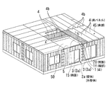
図1〜図6に示すように、梁1によって床パネル4の支持する床部45の支持構造は、吹き抜け5を有する部屋50の上階の床部45を構築するものであって、壁体2a、2b、2cと、梁1と、補強梁8と、床パネル4とを備えている。
【0018】
吹き抜けを有する部屋50は、対向する一対の壁体2a、2bと、この壁体2a、2bと直交する壁体2cと、この壁体2cと対向配置され、該壁体2a、2bの上端部間を架け渡すようにして設けられた支持梁2dとで囲まれた平面視矩形状の空間である。ここで、支持梁2dの上面は、壁体2a、2b、2cの上端面と面一に配置されている。
【0019】
壁体2a、2b、2cは、図1〜図5に示すように、縦横の框材を矩形枠状に組み付け、その内側に補強桟材を縦横に組み付けてなる枠体の表裏両面に合板等の面材を貼設することで構成される壁パネル3、3を連結して立設することによって形成されている。そして、これら壁体2a、2b、2cのうち対向する一対の壁体2a、2bは、上端部に接続用切欠部6aが形成された補助壁部6を該壁体2a、2bの中央部に配置させ、接続用切欠部6aを互いに向き合わせるようにして壁パネル3、3を連結して立設することによって形成されている。
【0020】
よって、壁体2a、2bの上端部には、壁体2a、2bの上端面と表面とに開口する凹部7、7が形成されている。そして、この凹部7、7に後述する梁本体1aがその上面1gを床パネル4の上面4eと面一になるようにして嵌め込まれている。
【0021】
ここで、補助壁部6は、木材等で形成された長尺な部材であり、その部材幅6cが後述する梁本体1aの幅1dと等しくなっている。また、壁体2a、2bのうち屋外側に配置された壁体2aを外壁体2aとし、この外壁体2aを構成する壁パネル3を外壁パネル3aとする。また、同様に、屋内側に配置された壁体2bを内壁体2bとし、内壁体2bを構成する壁パネル3を内壁パネル3bとする。
【0022】
梁1は、図1〜図6に示すように、両端部1f、1fが外壁体2aおよび内壁体2bの凹部7、7にそれぞれ固定された梁本体1aと、この梁本体1aの側面15、20に固定された受材1b、1bとを備えている。
【0023】
梁本体1aは、木材等で形成された平面視矩形状の長尺な部材であり、両端部1f、1fには、凹部7、7に対してそれぞれ上方に配置された切欠部1c、1cが形成されている。
【0024】
受材1bは、梁本体1aと同様の平面視矩形状の部材であって、外内壁体2a、2bの上端面からの凹部7、7の深さ6bと、梁本体1aの下面から受材1bの上面10bまでの長さ1eとが等しくなるように、梁本体1aの両方の側面15、20にそれぞれ接着剤13と釘11とによって固定されている。ここで、梁本体1aが吹き抜け5に面する側面15には、連結された2つの床パネル4の短辺の長さと同程度の長さに形成された受材1bが、内壁体2b側から延在するようにして固定されている。また、側面15と対向する他方の側面20には、床パネル4の長辺の長さと同程度の長さに形成された受材1bが、外内壁体2a、2b間を延在するようにして固定されている。
【0025】
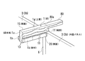
補強梁8は、図1および図2に示すように、平面視矩形状の長尺な木材等であって、梁本体1aと直交するようにして外壁体2aの上端面に設けられている。そして、補強梁8の一方の端部8gには屋外側の切欠部1cに係合する係合部8aか形成されており、係合部8aが該切欠部1cに係合することによって、梁本体1aの屋外側の端部1fを押さえている。
【0026】
そして、補強梁8の屋外側に配置された側面8bは、外壁パネル3aの上端面に固定された胴差し12に当接され、補強梁8の下端面8cは外壁パネル3aの上端面に固定されている。そして、補強梁8の上面8hが梁本体1aの上面1gと面一になっている。また、屋内側の切欠部1cには、図3および図6に示すように、マグサ80の一方の端部80aが固定されており、このマグサ80の他方の端部80bは、内壁体2bに隣接した壁パネル33の上端面に固定されている。
【0027】
床パネル4は、図2〜図4に示すように、複数の框材4aを矩形枠状に組み立て枠体4bを形成し、この枠体4b内に補強桟材4cを縦横に取付け、枠体4bの上面に合板等の面材4dを貼設したものである。そして、側面20の受材1bの上面10bと、外内壁体2a、2b、2cの上端面とには、連結された4つの床パネル4が支持されており、部屋50の上階の右側に床部45が構築されている。また、側面15の受材1bの上面10bと、支持梁2dの上面と、内壁体2bの上端面とには、連結された2つの床パネル4が支持されており、部屋50の上階の左側に吹き抜け5を有する床部45が構築されている。
【0028】
次に、本実施の形態における吹き抜け5を有する部屋50の上階の床部45の施工方法について図1〜図6を参照して説明する。
まず、壁パネル3、3を連結し、外内壁体2a、2bと直交する壁体2cを立設するとともに、補助壁部6が壁体2a、2bの中央部に配置されるようにして、接続用切欠部6aを互いに向き合わせ、壁パネル3、3を連結して外内壁体2a、2bをそれぞれ立設する。次に、梁本体1aと、側面15に固定される受材1bと、側面20に固定される受材1bとを用意する。
【0029】
そして、外内壁体2a、2bのそれぞれの凹部7、7に接着剤13を塗布し、この凹部7、7に梁本体1aをその上面1gが床パネル4の上面4eと面一になるようにして嵌め込み固定する。次に、梁本体1aの側面15に、凹部7、7の深さ6bと、梁本体1aの下端部からの長さ1eとが等しくなるようにして、受材1bを内壁体2b側から延在するようにして接着剤13と釘11とで固定する。また、同様にして、梁本体1aの側面20に、受材1bを外内壁体2a、2b間を延在するようにして固定する。
【0030】
次に、屋外側の切欠部1cに補強梁8の係合部8aを係合し、梁本体1aの上面10bと補強梁8の上面8hとを面一にする。この際に、梁本体1aと直交するようにして、補強梁8の屋外側の側面8bを胴差し12の当接し、補強梁8の下端面8cを外壁パネル3aの上端面に固定する。また、マグサ80の一方の端部80aを屋内側の切欠部1cに固定し、このマグサ80の他方の端部80bを、壁パネル33の上端面に固定する。そして、支持梁2dの上面と壁体2a、2b、2cの上端面とが面一になるようにして、支持梁2dを外内壁体2a、2bの上端部間に設ける。
【0031】
次に、側面15の受材1bの上面10bと、支持梁2dの上面と、内壁体2bの上端面とに2つの床パネル4をその上面4eが梁本体1aの上面1gと面一になるようにして支持させ、部屋50の上階の左側に吹き抜け5を有する床部45を構築する。また、側面20の受材1bの上面10bと、壁体2a、2b、2cの上端面とに4つの床パネル4を同様にして支持させ、部屋50の上階の右側に床部45を構築する。
【0032】
以上により、本実施の形態によれば、次のような効果が得られる。
▲1▼床パネル4は梁本体1aの側面15、20に固定された受材1b、1bによって支持されているので、梁本体1aの上面1gで床パネル4を支持している場合と比して、梁本体1aの下端部の位置が上方に配置され、梁本体1aの下方に取付けられる天井部材をさらに上方に配置することができる。
【0033】
したがって、天井高が高い部屋50を構築することができ、室内空間を広く感じさせることができる。また、床パネル4の上面4eが梁本体1aの上面1gと面一になっているので、受材1bに支持された床パネル4の上面4eと梁本体1aの上面1gとが平坦になり、凹凸がない床部45を構築することができる。したがって、床部45の上面に絨毯やフローリング等の床仕上げ材を凹凸が形成されることなく、平坦に敷き詰めることができる。
【0034】
▲2▼凹部7、7に梁本体1aがその上面1gを床パネル4の上面4eと面一になるようにして嵌め込まれているので、外内壁体2a、2bの上端部間に床パネル4の上面4eと面一なる梁1を部屋50の中央部に設けることができる。また、凹部7、7の深さ6bと、梁本体1aの下面からの長さ1eとが等しくなっているので、受材1bの上面10bと、外内壁体2a、2bの上端面とが面一に配置され、床パネル4を受材1bの上面10bと、外内壁体2a、2bの上端面とに水平に固定することができる。
【0035】
▲3▼補強梁8の係合部8aが屋外側の切欠部1cに係合することによって、梁本体1aの屋外側の端部1fを押さえるので、外壁体2aに梁本体1aの屋外側の端部1fを強固に固定することができる。また、補強梁8の上面8hが梁本体1aの上面1gと面一になっているので、補強梁8の上面8hが床パネル4の上面4eと平坦なり、床部45に凹凸が生じることがない。
【0036】
▲4▼受材1bが梁本体1aの両方の側面15、20に固定されている部位では、梁本体1aの両方の側面15、20に床パネル4を固定することができ、上階の床部45を支持する壁パネル3や柱等を部屋50の中央部に設ける必要がない。したがって、壁パネル3等による間仕切りが形成されない部屋50を構築することができる。また、受材1bが梁本体1aの一方の側面15に固定されている部位では、受材1bが固定されている側面20にのみ床パネル4を固定することよって、部屋50の左側の床部45に吹き抜け5を設けることができる。
【0037】
▲5▼凹部7、7に梁本体1aをその上面1gが床パネル4の上面4eと面一になるようにして嵌め込み固定することによって、外内壁体2a、2bの上端部間に床パネル4の上面4eと面一なる梁1を部屋50の中央部に設けることができる。そして、梁本体1aの側面15、20に、凹部7、7の深さ6bと、梁本体1aの下端部からの長さ1eとが等しくなるようにして、受材1b、1bをそれぞれ固定することによって、床パネル4を受材1bと外内壁体2a、2bとに水平に支持させることができる。よって、梁本体1aの下端部の位置は上方に配置されるので、梁本体1aの下方に取付けられる天井部材を上方に配置することができる。したがって、天井高が高い部屋50を構築することができ、室内空間を広く感じさせることができる。
【0038】
そして、側面15の受材1bの上面10bと、支持梁2dの上面と、内壁体2bの上端面とに2つの床パネル4をその上面4eが梁本体1aの上面1gと面一になるようにして支持させることによって、部屋50の上階の左側に吹き抜け5を有する平坦な床部45を構築することができる。また、側面20の受材1bの上面10bと、壁体2a、2b、2cの上端面とに4つの床パネル4を同様にして支持させることによって、部屋50の上階の右側に平坦な床部45を構築する。
【0039】
【発明の効果】
請求項1記載の発明によれば、床パネルは受材によって支持されているので、梁本体の下方に取付けられる天井部材を上方に配置することができる。したがって、天井高が高い部屋を構築することができ、室内空間を広く感じさせることができる。また、床パネルの上面が梁本体の上面と面一になっているので、凹凸がない床部を構築することができる。したがって、床部の上面に絨毯やフローリング等の床仕上げ材を凹凸が形成されることなく、平坦に敷き詰めることができる。
【0040】
また、凹部に梁本体がその上面を床パネルの上面と面一になるようにして嵌め込まれているので、壁体の上端部間に床パネルの上面と面一なる梁を設けることができる。また、凹部の深さと、梁本体の下面からの長さとが等しくなっているので、受材の上面と、壁体の上端面とが面一に配置され、床パネルを受材と壁体とに水平に固定することができる。
【0041】
請求項2記載の発明によれば、請求項1と同様の効果を得られることは勿論のこと、補強梁はその係合部を切欠部に係合することによって、梁本体の端部を押さえるので、壁体に梁本体の端部を強固に固定することができる。また、補強梁の上面が梁本体の上面と面一になっているので、床部に凹凸が生じることがない。
【0042】
請求項3記載の発明によれば、請求項1または2と同様の効果を得られることは勿論のこと、受材が梁本体の両方の側面に固定されている場合には、梁本体の両方の側面に床パネルを固定することができ、床部を支持する壁パネル等を部屋内に設ける必要がない。したがって、間仕切りが形成されない部屋を構築することができる。また、受材が梁本体の一方の側面に固定されている場合には、受材が固定されている側面にのみ床パネルを固定することよって、部屋に吹き抜けを設けることができる。
【0043】
請求項4記載の発明によれば、壁体に梁本体の端部を固定した後、該梁本体の側面に受材を固定することによって、該梁本体の側面に沿って、受材の上面に床パネルを支持させることができる。よって、梁本体の下端部の位置が上方に配置され、梁本体の下方に取付けられる天井部材を上方に配置することができる。したがって、室内空間を広く感じさせることができる。そして、受材に床パネルをその上面が梁本体の上面と面一になるようにして支持させることによって、受材に支持される床パネルの上面と梁本体の上面とが平坦になり、凹凸がない床部を構築することができる。したがって、床部を平坦に敷き詰めることができる。
【図面の簡単な説明】
【図1】本発明の実施の形態の一例を示すもので、梁本体と補強梁とが壁体に固定される前の状態を示す分解斜視図である。
【図2】同、吹き抜けに面する床部の屋外側の支持構造を示す斜視図である。
【図3】同、建物の上階の床パネルが固定される前の状態を示す斜視図である。
【図4】同、建物の上階の床パネルが固定された状態を示す斜視図である。
【図5】同、図4中の床部の支持構造を示したA−A線断面図である。
【図6】同、床部の屋内側の支持構造を示す斜視図である。
【符号の説明】
1 梁
1a 梁本体
1b 受材
1c 切欠部
1e 長さ(受材)
1f 端部(梁本体)
1g 上面(梁本体)
10b 上面(受材)
2a、2b 壁体(外壁体、内壁体)
15、20 側面
4 床パネル
4e 上面(床パネル)
6b 深さ(凹部)
7 凹部
8 補強梁
8a 係合部(補強梁)
8g 端部(補強梁)
8h 上面(補強梁)
45 床部[0001]
BACKGROUND OF THE INVENTION
The present invention relates to a floor support structure and a floor construction method.
[0002]
[Background technology]
In recent years, the construction of houses has been industrialized. For example, in prefabricated houses, rectangular plates such as floor panels, wall panels, ceiling panels, etc. that have been formed in the factory in advance without using columns and beams. There is known a construction method (hereinafter referred to as a panel construction method) for forming floors, walls, ceilings, and the like by arranging shaped panels.
[0003]
In such a house, when building a large room that can be used for parties, etc., as a support structure for the upper floor, a beam is provided between the upper ends of the wall panels that form the center of the room, May support the upper floor. And as an example which shows the support structure of the floor part of an upper floor, the technique of Unexamined-Japanese-Patent No. 7-109786 is known, for example. In this technology, a floor panel is laid on a standing wall panel and a beam, and a ceiling member is attached to the lower part of the beam, thereby constructing a floor portion and a ceiling surface of an upper floor. is there.
[0004]
[Problems to be solved by the invention]
By the way, when constructing a large room that can be used for parties or the like, it is necessary to set a large beam formation in the center of the room in order to support the load on the upper floor.
However, in the technique of the above publication, a floor panel is laid on the upper end surface of the wall panel and the upper surface of the beam provided between the upper end portions of the wall panel, and a ceiling member is attached below the beam. When the beam formation becomes large, the ceiling member attached below the beam is arranged below, and even in a large room, a room with a low ceiling height is formed, which may make the indoor space feel narrow.
[0005]
This invention is made | formed in view of the said situation, and it aims at providing the support structure of the floor part which can form a room with high ceiling height, and the construction method of a floor part.
[0006]
[Means for Solving the Problems]
In order to solve the above-mentioned problems, the invention according to
Wall bodies (outer wall bodies, inner wall bodies) 2a and 2b are arranged on the
[0007]
According to the first aspect of the present invention, since the floor panel 4 is supported by the
[0009]
Further, since the beam main body 1a is fitted in the recesses 7 and 7 so that the upper surface 1g thereof is flush with the
[0010]
According to a second aspect of the invention, for example, as shown in FIGS. 1 and 2, in the support structure of the floor portion 45 according to
[0011]
According to the second aspect of the present invention, since the reinforcing
[0012]
The invention according to
[0013]
According to invention of
[0014]
Invention of claim 4, wherein, for example, as shown in FIGS. 1 to 5, in the construction method of the floor portion 45 for supporting the floor panel 4 by the
[0015]
According to invention of Claim 4 , after fixing the
[0016]
Therefore, the
[0017]
DETAILED DESCRIPTION OF THE INVENTION
Hereinafter, embodiments of the present invention will be described in detail with reference to FIGS.
As shown in FIGS. 1-6, the support structure of the floor part 45 which the floor panel 4 supports by the
[0018]
The
[0019]
As shown in FIGS. 1 to 5, the wall bodies 2 a, 2 b, and 2 c are assembled on both front and back surfaces of a frame body in which vertical and horizontal frame members are assembled in a rectangular frame shape, and reinforcing bars are assembled in the vertical and horizontal directions. It is formed by connecting and standing up the
[0020]
Therefore, the upper ends of the walls 2a, 2b are formed with recesses 7, 7 that open to the upper ends and the surfaces of the walls 2a, 2b. And the beam main body 1a mentioned later is inserted in this recessed part 7 and 7 so that the upper surface 1g may become flush with the
[0021]
Here, the
[0022]
As shown in FIGS. 1 to 6, the
[0023]
The beam main body 1a is a long member having a rectangular shape in plan view formed of wood or the like, and both
[0024]
The receiving
[0025]
As shown in FIGS. 1 and 2, the reinforcing
[0026]
And the
[0027]
As shown in FIGS. 2 to 4, the floor panel 4 is formed by assembling a plurality of
[0028]
Next, the construction method of the floor part 45 on the upper floor of the
First, the
[0029]
Then, an adhesive 13 is applied to the recesses 7 and 7 of the outer and inner wall bodies 2a and 2b, and the beam body 1a is placed on the recesses 7 and 7 so that the upper surface 1g thereof is flush with the
[0030]
Next, the engaging portion 8a of the reinforcing
[0031]
Next, two floor panels 4 are arranged on the
[0032]
As described above, according to the present embodiment, the following effects can be obtained.
(1) Since the floor panel 4 is supported by the receiving
[0033]
Therefore, the
[0034]
(2) Since the beam body 1a is fitted in the recesses 7 and 7 so that the upper surface 1g thereof is flush with the
[0035]
(3) Since the engaging portion 8a of the reinforcing
[0036]
(4) At the portion where the receiving
[0037]
(5) By fitting and fixing the beam body 1a in the recesses 7 and 7 so that the upper surface 1g thereof is flush with the
[0038]
Then, two floor panels 4 are arranged on the
[0039]
【The invention's effect】
According to the first aspect of the present invention, since the floor panel is supported by the receiving material, the ceiling member attached below the beam main body can be arranged upward. Therefore, a room with a high ceiling height can be constructed, and the indoor space can be felt wide. Moreover, since the upper surface of the floor panel is flush with the upper surface of the beam main body, a floor portion having no irregularities can be constructed. Accordingly, floor finishing materials such as carpets and flooring can be laid flat on the upper surface of the floor without forming irregularities.
[0040]
In addition , since the beam main body is fitted in the recess so that the upper surface thereof is flush with the upper surface of the floor panel, a beam that is flush with the upper surface of the floor panel can be provided between the upper ends of the wall bodies. In addition, since the depth of the recess is equal to the length from the lower surface of the beam body, the upper surface of the receiving material and the upper end surface of the wall body are arranged flush with each other, and the floor panel is connected to the receiving material and the wall body. Can be fixed horizontally.
[0041]
According to the second aspect of the invention, the effect similar to that of the first aspect can be obtained, and the reinforcing beam can hold the end portion of the beam body by engaging the engaging portion with the notch portion. Therefore, the end of the beam body can be firmly fixed to the wall. Moreover, since the upper surface of the reinforcing beam is flush with the upper surface of the beam body, the floor portion is not uneven.
[0042]
According to the third aspect of the present invention, the same effect as in the first or second aspect can be obtained, and when the receiving material is fixed to both side surfaces of the beam main body, The floor panel can be fixed to the side of the wall, and there is no need to provide a wall panel or the like for supporting the floor in the room. Therefore, a room in which no partition is formed can be constructed. Further, when the receiving material is fixed to one side surface of the beam main body, it is possible to provide an atrium in the room by fixing the floor panel only to the side surface to which the receiving material is fixed.
[0043]
According to invention of Claim 4 , after fixing the edge part of a beam main body to a wall body, by fixing a receiving material to the side surface of this beam main body, along the side surface of this beam main body, the upper surface of a receiving material Can support the floor panel. Therefore, the position of the lower end part of the beam main body is arranged upward, and the ceiling member attached below the beam main body can be arranged upward. Therefore, the indoor space can be made to feel wide. Then, by allowing the receiving material to support the floor panel so that the upper surface of the floor panel is flush with the upper surface of the beam body, the upper surface of the floor panel supported by the receiving material and the upper surface of the beam body become flat. It is possible to build a floor part without. Therefore, the floor can be laid flat.
[Brief description of the drawings]
FIG. 1 is an exploded perspective view showing a state before a beam main body and a reinforcing beam are fixed to a wall, showing an example of an embodiment of the present invention.
FIG. 2 is a perspective view showing a support structure on the outdoor side of the floor facing the atrium.
FIG. 3 is a perspective view showing a state before the floor panel on the upper floor of the building is fixed.
FIG. 4 is a perspective view showing a state where the floor panel on the upper floor of the building is fixed.
5 is a cross-sectional view taken along the line AA showing the support structure for the floor portion in FIG. 4; FIG.
FIG. 6 is a perspective view showing a support structure on the indoor side of the floor portion.
[Explanation of symbols]
1 Beam
1f End (beam main body)
1g Top surface (beam main body)
10b Upper surface (receiving material)
2a, 2b Wall (outer wall, inner wall)
15, 20 Side surface 4
6b Depth (concave)
7
8g end (reinforcement beam)
8h Top surface (reinforcement beam)
45 Floor
Claims (4)
前記梁本体の端部側には壁体が配置されており、前記壁体の上端部には壁体の上端面と表面とに開口する凹部が形成されており、この凹部に前記梁本体がその上面を前記床パネルの上面と面一になるようにして嵌め込まれ、さらに、前記壁体の上端面からの凹部の深さと、梁本体の下面から受材の上面までの長さとが等しくなっていることを特徴とする床部の支持構造。In the support structure of the floor portion that supports the floor panel by the beam, the beam includes a beam body and a receiving member fixed to a side surface of the beam body, and the floor panel is supported by the receiving member, The upper surface of the floor panel is flush with the upper surface of the beam body ,
A wall body is disposed on the end side of the beam body, and a recess opening at the upper end surface and the surface of the wall body is formed at the upper end portion of the wall body. The upper surface of the wall panel is fitted to the upper surface of the floor panel, and the depth of the recess from the upper end surface of the wall body is equal to the length from the lower surface of the beam body to the upper surface of the receiving member. The floor support structure is characterized by that.
Priority Applications (1)
| Application Number | Priority Date | Filing Date | Title |
|---|---|---|---|
| JP2001340947A JP3875069B2 (en) | 2001-11-06 | 2001-11-06 | Floor support structure, floor construction method |
Applications Claiming Priority (1)
| Application Number | Priority Date | Filing Date | Title |
|---|---|---|---|
| JP2001340947A JP3875069B2 (en) | 2001-11-06 | 2001-11-06 | Floor support structure, floor construction method |
Publications (2)
| Publication Number | Publication Date |
|---|---|
| JP2003138682A JP2003138682A (en) | 2003-05-14 |
| JP3875069B2 true JP3875069B2 (en) | 2007-01-31 |
Family
ID=19155074
Family Applications (1)
| Application Number | Title | Priority Date | Filing Date |
|---|---|---|---|
| JP2001340947A Expired - Fee Related JP3875069B2 (en) | 2001-11-06 | 2001-11-06 | Floor support structure, floor construction method |
Country Status (1)
| Country | Link |
|---|---|
| JP (1) | JP3875069B2 (en) |
-
2001
- 2001-11-06 JP JP2001340947A patent/JP3875069B2/en not_active Expired - Fee Related
Also Published As
| Publication number | Publication date |
|---|---|
| JP2003138682A (en) | 2003-05-14 |
Similar Documents
| Publication | Publication Date | Title |
|---|---|---|
| US5901524A (en) | Grid-like building panel framework and members for making such panel framework | |
| JP3875069B2 (en) | Floor support structure, floor construction method | |
| JP3045256U (en) | Building floor components | |
| JPH017775Y2 (en) | ||
| JP3866356B2 (en) | Wall base and floor finish storage structure | |
| JP4801856B2 (en) | Unit building | |
| JP3448397B2 (en) | Unit building | |
| JP2708711B2 (en) | Unit housing and its construction method | |
| JP3247785B2 (en) | Ceiling base panel and ceiling base structure using the same | |
| JP3735213B2 (en) | Roof structure | |
| JPH09296520A (en) | Panel structure and building unit | |
| JPH08311999A (en) | Unit building | |
| KR200229303Y1 (en) | The corner type vertical unit for assembly of the light weight wall | |
| JP3701707B2 (en) | Ceiling structure of building unit | |
| JP3086369B2 (en) | Building construction method | |
| JPH09125565A (en) | Wooden structural member for construction | |
| JP3161567B2 (en) | Building construction method | |
| JP3530808B2 (en) | Method of forming wall surface of house using panel body and house | |
| JP3126572B2 (en) | Boundary wall structure and building wall construction method of building unit | |
| JPS6065845A (en) | Room unit without floor | |
| JP2000096721A (en) | Unit building | |
| JP2001123539A (en) | Floor construction of building unit | |
| JPH09125523A (en) | Vestibule unit of unit type building | |
| JP2000129823A (en) | Columnar building member | |
| JPH108618A (en) | Floor structure of building unit |
Legal Events
| Date | Code | Title | Description |
|---|---|---|---|
| A621 | Written request for application examination |
Free format text: JAPANESE INTERMEDIATE CODE: A621 Effective date: 20041101 |
|
| A977 | Report on retrieval |
Free format text: JAPANESE INTERMEDIATE CODE: A971007 Effective date: 20060713 |
|
| A131 | Notification of reasons for refusal |
Free format text: JAPANESE INTERMEDIATE CODE: A131 Effective date: 20060725 |
|
| A521 | Written amendment |
Free format text: JAPANESE INTERMEDIATE CODE: A523 Effective date: 20060915 |
|
| TRDD | Decision of grant or rejection written | ||
| A01 | Written decision to grant a patent or to grant a registration (utility model) |
Free format text: JAPANESE INTERMEDIATE CODE: A01 Effective date: 20061024 |
|
| A61 | First payment of annual fees (during grant procedure) |
Free format text: JAPANESE INTERMEDIATE CODE: A61 Effective date: 20061025 |
|
| R150 | Certificate of patent or registration of utility model |
Free format text: JAPANESE INTERMEDIATE CODE: R150 |
|
| FPAY | Renewal fee payment (event date is renewal date of database) |
Free format text: PAYMENT UNTIL: 20091102 Year of fee payment: 3 |
|
| S111 | Request for change of ownership or part of ownership |
Free format text: JAPANESE INTERMEDIATE CODE: R313111 |
|
| FPAY | Renewal fee payment (event date is renewal date of database) |
Free format text: PAYMENT UNTIL: 20091102 Year of fee payment: 3 |
|
| R350 | Written notification of registration of transfer |
Free format text: JAPANESE INTERMEDIATE CODE: R350 |
|
| FPAY | Renewal fee payment (event date is renewal date of database) |
Free format text: PAYMENT UNTIL: 20091102 Year of fee payment: 3 |
|
| FPAY | Renewal fee payment (event date is renewal date of database) |
Free format text: PAYMENT UNTIL: 20101102 Year of fee payment: 4 |
|
| FPAY | Renewal fee payment (event date is renewal date of database) |
Free format text: PAYMENT UNTIL: 20101102 Year of fee payment: 4 |
|
| FPAY | Renewal fee payment (event date is renewal date of database) |
Free format text: PAYMENT UNTIL: 20111102 Year of fee payment: 5 |
|
| FPAY | Renewal fee payment (event date is renewal date of database) |
Free format text: PAYMENT UNTIL: 20121102 Year of fee payment: 6 |
|
| FPAY | Renewal fee payment (event date is renewal date of database) |
Free format text: PAYMENT UNTIL: 20131102 Year of fee payment: 7 |
|
| LAPS | Cancellation because of no payment of annual fees |