JP3866356B2 - Wall base and floor finish storage structure - Google Patents
Wall base and floor finish storage structure Download PDFInfo
- Publication number
- JP3866356B2 JP3866356B2 JP04473697A JP4473697A JP3866356B2 JP 3866356 B2 JP3866356 B2 JP 3866356B2 JP 04473697 A JP04473697 A JP 04473697A JP 4473697 A JP4473697 A JP 4473697A JP 3866356 B2 JP3866356 B2 JP 3866356B2
- Authority
- JP
- Japan
- Prior art keywords
- floor
- fixed
- wall base
- joist
- horizontal
- Prior art date
- Legal status (The legal status is an assumption and is not a legal conclusion. Google has not performed a legal analysis and makes no representation as to the accuracy of the status listed.)
- Expired - Fee Related
Links
Images


Landscapes
- Load-Bearing And Curtain Walls (AREA)
- Floor Finish (AREA)
Description
【0001】
【発明の属する技術分野】
本発明は木造軸組工法によって建築された壁下地材と床仕上げ材の納め構造に関するものである。
【0002】
【従来の技術】
従来から、木造軸組工法によって住宅の建築を行う場合、構造用面材と称されている板状体を筋かいの代わりに、または筋かいと共に用いて地震や風圧などの水平方向の力に対向する耐力壁とすることが行われており、例えば、内装壁側においては、図8に示すように、土台等の横架材21の内側面に付き合わせ状態で固着している大引22上に根太23を架設、固定し、この根太23上に床下地材24を張設する一方、内装壁を形成する壁下地材25は、その上側縁辺部と両側縁辺部とを構造軸材の内側面に釘着或いはビス止めによって固定された構造としている。
【0003】
【発明が解決しようとする課題】
しかしながら、上記のような壁下地板と床下地材との納め構造によれば、壁下地材25の下側縁辺部が横架材21に固着されない構造となっているので、地震時における水平方向の揺れに対する耐力を充分に発揮させることができないという欠点がある。このような欠点は、根太23を横架材21の下端部側に固定し、該根太23上に張設した床下地材24の端部上面から上方に露出している横架材21の内側面に壁下地材25の下側縁辺部を添設して固着すれば解消できるが、このように施工すると、横架材21が床面から上方に突出した状態となって、該横架材21上に対する和室の敷居や洋室のドアの沓摺の取付けや高齢者のためのバリヤフリーの床材の形成に支障をきたすという問題点があった。
【0004】
一方、このような問題点は、図9に示すように横架材21の内側面に壁下地材25の下端部を固着し、該下端部上に根太23を固着したのちこの根太23上に床下地材24の端部を固着した構造とすることによって解消し得るが、この構造では壁下地材25を施工する際には床下地材24が存在していないために、壁施工の足場の確保ができなく、その上、壁内に配線や配管の施工作業が行えなくなるという問題点がある。また、いずれの構造においても、壁下地材と床下地材との施工後において、床仕上げ材の施工を行わなければならない。本発明はこのような問題点を全面的に解消し得る壁下地材と床仕上げ材の納め構造を提供することを目的とするものである。
【0005】
【課題を解決するための手段】
上記目的を達成するために、本発明の壁下地材と床仕上げ材の納め構造は、土台、胴差、床梁、桁などの横架材に対する壁下地材と床仕上げ材との納め構造であって、横架材の内側面に根太受け材を固着し、この根太受け材上に根太の一端部をその上面が上記横架材の上面よりも上方に位置させて固着すると共に該根太上に床仕上げ材を張設し、さらに、上記横架材の上面内側部上に上端部を上記根太の上面から突出させた状態にして壁下地受け材を固着し、該壁下地受け材の上端部内側面に壁下地材の下端部を固着した構造としている。
【0006】
さらに、上記壁下地材と床仕上げ材の納め構造において、本発明は根太受け材を、その上面が横架材の上面よりも下方に位置させた状態で該横架材の内側面中央部に固着していることを特徴とするものであり、請求項2に係る発明は、根太受け材を、その上面が横架材の上面に一致させた状態で該横架材の内側面上端部に固着していることを特徴としている。また、請求項3に記載したように、根太の端部下端の角部を断面逆L字状に切り欠いて該切欠部を根太受け材に係合させた状態で固着した構造としてもよい。
【0007】
【作用】
横架材の内側面に固着した根太受け材上に根太の一端部を固着し、この根太上に床仕上げ材を張設するものであるから、通常の床施工手順と同様に、床仕上げ材の施工が能率よく行える。さらに、根太の上面が横架材の上面よりも上方に突出しているので、横架材上に対する和室の敷居や洋室のドアの沓摺の取付けが床仕上げ材の面に合わせて施工できる。また、横架材の上面内側部上に固着した壁下地受け材の上端部を上記根太の上面から上方に突出させているので、まず、根太上に床仕上げ材を施工してこの床仕上げ材を足場に利用しながら壁施工や壁内への配線、配管作業が可能となる。壁下地材は床仕上げ材の施工後に施工されるが、その際、該壁下地材の左右端縁部を柱等の左右縦軸材の内側面に当てがい、上端縁部を上側の横架材に、下端縁部を上記壁下地受け材の内側面にそれぞれ釘打ちによって固着することにより水平耐力に優れた壁構造が得られる。
【0008】
さらに、本発明においては、根太受け材をその上面が横架材の上面よりも下方に位置させて該横架材の内側面中央部に固着しているので、床全体を低位置に施工することができる一方、請求項2に係る発明においては、根太受け材をその上面が横架材の上面に一致させて横架材の内側面上端部に固着しているので、床全体を高位置に施工することができ、従って、床面の高さを上記低位置と高位置間の範囲内で自由に設定し得る。
【0009】
また、請求項3に記載したように、根太の端部下端の角部を断面逆L字状に切り欠いて該切欠部を根太受け材に係合させた状態で固着した構造とすることによって、根太受け材に根太を強固に固定することができ、この根太上に床仕上げ材を張設することによって水平耐力を発揮する床構造を構成することができる。
【0010】
【発明の実施の形態】
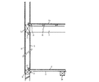
次に、本発明の具体的な実施例を図面について説明すると、図1〜図3は木造軸組工法によって施工された壁構造と床構造を示すもので、壁構造は、左右に一定間隔を存して立設した柱或いは間柱からなる縦軸材1、1aと上下に一定間隔を存して並設した土台や胴差、梁、桁などの横架材2、2aとを組み合わせ接合してなる方形枠状の構造軸材の内外面(以下、室外側に向けた面を外側面、室内側に向けた面を内側面とする)に、構造用合板やパーティクルボード、シージングボード、OSB(オリエンテッドストランドボード)、VSF(火山性ガラス質複層板)等の面材耐力壁として適した板材よりなる縦長方形状の外側壁下地材3と内側壁下地材4とを張設してなるものである。
【0011】
一方、床構造は、一階側においては土台などの横架材2と該横架材2から室内側に向かって一定間隔を存して並設した大引きや梁などの横架材2bとの間に床下地材を兼ね備えた根太5を架設してその両端部をこれらの横架材2、2bに固定、支持させると共に上記根太5を横架材の長さ方向に一定間隔毎に並設して隣接する根太5、5の上面間に合板やパーティクルボードなどの板材を介してまたは直接、化粧単板貼り合板からなる床仕上げ材6を施工してなるものであり、二階側においては一階側と同一の床構造としてもよいが、図においては横架材2aに端部を突き合わせ状に固着してなる隣接する床梁7、7の上面間に床根太8、8を該床梁7の長さ方向に一定間隔毎に架設、固着し、これらの床根太8の上面に床仕上げ材6aを施工してなるものである。
【0012】
上記外側壁下地材3はその四方周縁部を方形枠状の構造軸材を構成した左右縦軸材1、1aと上下横架材2、2aの外面に釘打ちによって固着して水平耐力を有する壁下地材3の納め構造を構成している。一方、内側壁下地材4はこの下地材4を施工する前に上記床仕上げ材6を施工して作業足場を確保し得る構造となっており、かつ該内側壁下地材4も水平耐力を有する納め構造を構成している。
【0013】
これらの内側壁下地材4と床仕上げ材6の納め構造を説明すると、土台である横架材2の内側面中央部に角棒形状の根太受け材9を、その上面を横架材2の上面から一定寸法だけ下方に位置させた状態で水平に添接してビス又は釘打ちにより横架材2に固着してあり、さらに、この横架材2の上面における内側、即ち、室内寄り側の上面部に同じく角棒形状の壁下地受け材10を、その内側面が横架材2の内側面と同一垂直面上に連なるように載置した状態で釘打ち又はビス止めすることによって固着している。なお、壁下地受け材10の施工は、横架材2の内側稜角部、即ち、室内側の上側稜角部を定規に使用して該稜線角部に壁下地受け材10の内側面における下側稜角部を合わせることによって簡単且つ精度よく行うことができる。
【0014】
また、上記横架材2から室内側に一定間隔を存して該横架材2と平行にして上面が上記根太受け材9の上面と同一水平面上となるように大引きからなる横架材2bを固定してあり、これらの根太受け材9と横架材2bの上面間に上記床下地材を兼ね備えた根太5を複数本、横架材の長さ方向に一定間隔毎に架設してその両端部を根太受け材9と横架材2bに釘打ちすることによって固着している。そして、並設した根太5、5の上面間に床仕上げ材6を架設状態に張設し、針、ビス、場合によっては接着剤を併用して根太5に固着している。
【0015】
一方、土台である横架材2の上面内側部上に固着した上記壁下地受け材10は、上端部を該床仕上げ材6の上面に対して上方に突出させてその上面の高さを床仕上げ材6の床面よりも高くなるように形成されており、床仕上げ材6から突出した該壁下地受け材10の上端部内側面に内側壁下地材4の下端部を当接させてビス又は釘打ちにより固着している。この内側壁下地材4の上端部は上側横架材2aの内側面又は該横架材2aの下面に固着した上側壁下地受け材11の内側面に同じく或いはビス又は釘打ちにより固着されている。
【0016】
内側壁下地材4の施工は上述したように、床仕上げ材6の施工後に該床仕上げ材6を作業足場に利用して室内側から行うことができ、また、爾後の壁内への配線、配管作業も同様にして行うことができる。なお、この内側壁下地材4の左右両端部は隣接する縦軸材1、1aの内側面に固着している。
【0017】
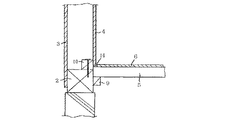
図4、図5は本発明の別な実施例を示すもので、上記実施例においては、横架材2の内側面に固着した根太受け材9をその上面が横架材2の上面よりも下方に位置するように横架材2の内側面中央部に固着しているが、この実施例においては根太受け材9の上面を横架材2の上面に面一状態にして固着しているものである。また、横架材2から室内側に一定間隔を存して該横架材2と平行に配設、固定してなる大引きからなる横架材2bを、その上面が根太受け材9の上面に同一水平面上に一致するように軸組してあり、これらの根太受け材9と横架材2bの上面間に上記実施例と同じく床下地材を兼ね備えた根太5を複数本、横架材の長さ方向に一定間隔毎に架設してその両端部を根太受け材9と横架材2bに釘打ちすることによって固着し、並設した根太5、5の上面間に床仕上げ材6を架設状態に張設して針、ビス又は場合によっては接着剤を併用して根太5に固着している。
【0018】
一方、壁下地受け材10は上記実施例と同じく、その内側面を横架材2の内側面と同一垂直面上に連設した状態にして横架材2の上面における内側部上に固着してあり、内側壁下地材4はその上端部を上側の横架材2aの内側面下部に当接させると共に下端部を上記根太5上に張設した床仕上げ材6の上面から突出している壁下地受け材10の内側面に当接させ且つ下端面を床仕上げ材6の端部上面に突き当て状態にして張設してその上下端部を上側横架材2aと壁下地受け材10にビス又は釘打ちにより固着している。
【0019】
従って、この床仕上げ材6の納め構造によれば、横架材2の上面から下方における該横架材2の内側面に根太受け材9を固着してなる上記実施例に比べて、根太受け材9を上位置に固定しているから、床全体を高位置に施工することができるものである。その他の構造については上記実施例と同様であるのでその説明を省略する。
【0020】
図6は本発明のさらに別な実施例を示すもので、根太5の両端下部の角部を断面逆L字状に切欠き、その切欠部12、13を根太受け材9と室内側の横架材2bとの対向する上側角部に係合させ、この状態でその両端部を根太受け材9と横架材2bに釘打ちすることによって固着しているものである。このように、根太5の両端部下端の角部を断面逆L字状に切り欠いて該切欠部12、13を根太受け材9と横架材2bにそれぞれ係合、固着した構造とすることによって、根太5が強固に固定され、従って、この根太5上に張設した床仕上げ材6が優れた水平耐力を発揮する床構造を構成することができるものである。
【0021】
なお、以上のいずれの実施例においても床仕上げ材6の端面を横架材2の上面内側部上に固着した壁下地受け材10の内側面に当接状態にして固着しているが、図7に示すように、該床仕上げ材6の端面を壁下地受け材10の内側面から内側壁下地材4の厚み以上の間隔14を存した状態にして根太5上に張設しておいてもよい。
【0022】
【発明の効果】
以上のように本発明の壁下地材と床仕上げ材の納め構造によれば、横架材の内側面に根太受け材を固着し、この根太受け材上に根太の一端部をその上面が上記横架材の上面よりも上方に位置させて固着すると共に該根太上に床仕上げ材を張設し、さらに、上記横架材の上面内側部上に上端部を上記根太の上面から突出させた状態にして壁下地受け材を固着し、該壁下地受け材の上端部内側面に壁下地材の下端部を固着してなるものであるから、根太が床下地材としての機能を兼備して床仕上げ材の施工性、ひいては住宅の建築が能率よく行うことができるものである。
【0023】
さらに、根太受け材上に架設された根太の上面が横架材の上面よりも上方に突出しているので、横架材上に対する和室の敷居や洋室のドアの沓摺の取付けが床仕上げ材の面に合わせて施工できるものであり、その上、横架材の上面内側部上に固着した壁下地受け材の上端部を上記根太の上面から上方に突出させているので、まず、根太上に床仕上げ材を施工してこの床仕上げ材を足場に利用しながら壁施工や壁内への配線、配管作業が可能となり、一方、壁下地材は床仕上げ材の施工後に施工されるが、その際、該壁下地材の左右端縁部を柱等の左右縦軸材の内側面に当てがい、上端縁部を上側の横架材に、下端縁部を上記壁下地受け材の内側面にそれぞれ釘打ちによって固着することにより水平耐力に優れた壁構造が得られるものである。
【0024】
また、請求項1に係る発明によれば、根太受け材をその上面が横架材の上面よりも下方に位置させて該横架材の内側面中央部に固着しているので、床全体を低位置に施工することができるものであり、請求項2に係る発明においては、根太受け材をその上面が横架材の上面に一致させて横架材の内側面上端部に固着しているので、横架材の内側稜角部を定規として該稜角部に合わせて根太受け材を取り付けることができ、その施工性が良好となるばかりでなく床全体を高位置に施工することができるものであり、従って、床面の高さを上記低位置と高位置間の範囲内で自由に設定し得るものである。
【0025】
また、請求項3に記載したように、根太の端部下端の角部を断面逆L字状に切り欠いて該切欠部を根太受け材に係合させた状態で固着した構造とすることにより根太受け材に根太を強固に固定することができ、従って、この根太5上に張設した床仕上げ材6が優れた水平耐力を発揮する床構造を構成することができるものである。
【図面の簡単な説明】
【図1】壁下地材と床仕上げ材との納め構造を示す簡略斜視図、
【図2】その簡略縦断正面図、
【図3】図2における要部の拡大縦断正面図、
【図4】本発明の別な実施例を示す簡略縦断正面図、
【図5】その要部の拡大縦断正面図、
【図6】根太の架設構造の変形例を示す簡略縦断正面図、
【図7】床仕上げ材の張設状態の変形例を示す簡略縦断正面図、
【図8】従来の壁構造の一例を示す簡略縦断側面図、
【図9】従来の壁構造の別な例を示す簡略縦断側面図。
【符号の説明】
1、1a 縦軸材
2、2a、2b 横架材
4 内側壁下地材
5 根太
6 床仕上げ材
9 根太受け材
10 壁下地受け材[0001]
BACKGROUND OF THE INVENTION
The present invention relates to a wall base material and floor finishing material storage structure constructed by a wooden frame construction method.
[0002]
[Prior art]
Conventionally, when building a house using a wooden frame construction method, a plate-like body called a structural surface material is used instead of a brace or together with a brace for horizontal forces such as earthquakes and wind pressure. For example, on the interior wall side, as shown in FIG. 8, the
[0003]
[Problems to be solved by the invention]
However, according to the storage structure of the wall base plate and floor base material as described above, the lower edge of the
[0004]
On the other hand, as shown in FIG. 9, the problem is that the lower end portion of the
[0005]
[Means for Solving the Problems]
In order to achieve the above object, the wall base material and floor finishing material storage structure of the present invention is a wall base material and floor finishing material storage structure for horizontal members such as foundations, waist differences, floor beams and girders. A joist support is fixed to the inner surface of the horizontal member, and one end of the joist is fixed on the joist support with its upper surface positioned above the upper surface of the horizontal member. A floor finishing material is stretched on the wall, and further, a wall base receiving material is fixed on the inner side of the upper surface of the horizontal member with the upper end protruding from the upper surface of the joist, and the upper end of the wall base receiving material is fixed. The lower end portion of the wall base material is fixed to the inner side surface of the unit.
[0006]
Further, in the above-mentioned wall base material and floor finish material storage structure, the present invention provides a joist support material in the center of the inner surface of the horizontal member with its upper surface positioned below the upper surface of the horizontal member. The invention according to
[0007]
[Action]
Since one end of the joist is fixed on the joist support fixed to the inner surface of the horizontal member, and the floor finish is stretched on the joist, the floor finish is the same as the normal floor construction procedure. Can be done efficiently. Furthermore, since the upper surface of the joist projects upward from the upper surface of the horizontal member, it is possible to install a Japanese-style sill or a western-style door pallet on the horizontal member in accordance with the surface of the floor finish. Moreover, since the upper end part of the wall foundation receiving material fixed on the inner surface of the upper surface of the horizontal member protrudes upward from the upper surface of the joist, the floor finish is first constructed on the joist. Wall construction, wiring into the wall, and piping work are possible while using as a scaffold. The wall base material is constructed after the floor finishing material has been installed. At that time, the left and right end edges of the wall base material are applied to the inner surface of the left and right vertical axis materials such as pillars, and the upper end edge is mounted on the upper side. A wall structure having excellent horizontal strength can be obtained by fixing the lower end edge of the material to the inner surface of the wall base receiving material by nailing.
[0008]
Furthermore, in the present invention , the joist support material is fixed to the center of the inner surface of the horizontal member with its upper surface positioned below the upper surface of the horizontal member, so the entire floor is constructed at a low position. On the other hand, in the invention according to
[0009]
Further, as described in
[0010]
DETAILED DESCRIPTION OF THE INVENTION
Next, a specific embodiment of the present invention will be described with reference to the drawings. FIGS. 1 to 3 show a wall structure and a floor structure constructed by a wooden frame construction method. Combine and join the vertical members 1 and 1a made up of existing columns or studs and the
[0011]
On the other hand, the floor structure is composed of a
[0012]
The outer
[0013]
The storage structure of the inner side
[0014]
Further, the horizontal member is extended by a large distance so that the upper surface thereof is on the same horizontal plane as the upper surface of the
[0015]
On the other hand, the above-mentioned wall
[0016]
As described above, the construction of the inner
[0017]
4 and 5 show another embodiment of the present invention. In the above embodiment, the upper surface of the
[0018]
On the other hand, the wall
[0019]
Therefore, according to the storage structure of the floor finishing material 6, compared with the above embodiment in which the
[0020]
FIG. 6 shows still another embodiment of the present invention, in which corners at both ends of the
[0021]
In any of the above embodiments, the end surface of the floor finishing material 6 is fixed in contact with the inner surface of the wall
[0022]
【The invention's effect】
As described above, according to the wall base material and floor finish material storage structure of the present invention, the joist support is fixed to the inner surface of the horizontal member, and one end of the joist is placed on the joist support. The floor finishing material is stretched on the joist and is fixed above the upper surface of the horizontal member, and the upper end is protruded from the upper surface of the joist on the inner side of the upper surface of the horizontal member. Since the wall base receiving material is fixed in a state and the lower end portion of the wall base material is fixed to the inner surface of the upper end of the wall base receiving material, the joist also functions as a floor base material. The workability of the finishing material, and thus the construction of the house, can be efficiently performed.
[0023]
Furthermore, since the upper surface of the joist laid on the joist support material protrudes above the upper surface of the horizontal material, the installation of the Japanese room sill and the western-style door pallet on the horizontal material It can be constructed according to the surface, and in addition, the upper end of the wall base receiving material fixed on the inner surface of the upper surface of the horizontal member protrudes upward from the upper surface of the joist. While constructing a floor finish and using this floor finish as a scaffold, wall construction, wiring into the wall, and piping work are possible, while the wall substrate is constructed after the floor finish is constructed. In this case, the left and right edge portions of the wall base material are applied to the inner side surfaces of the left and right vertical axis members such as pillars, the upper end edge portion is the upper horizontal member, and the lower end edge portion is the inner side surface of the wall base receiving material. A wall structure with excellent horizontal strength can be obtained by fixing each by nailing.
[0024]
Further, according to the invention according to claim 1 , the joist support material is fixed to the central portion of the inner surface of the horizontal member with its upper surface positioned below the upper surface of the horizontal member. In the invention according to
[0025]
Further, as described in
[Brief description of the drawings]
FIG. 1 is a simplified perspective view showing a storage structure of a wall base material and a floor finish material;
FIG. 2 is a simplified longitudinal sectional front view thereof,
FIG. 3 is an enlarged vertical front view of the main part in FIG.
FIG. 4 is a simplified longitudinal front view showing another embodiment of the present invention;
FIG. 5 is an enlarged vertical front view of the main part,
FIG. 6 is a simplified longitudinal front view showing a modification of the joist erection structure,
FIG. 7 is a simplified longitudinal sectional front view showing a modified example of the tensioned state of the floor finishing material,
FIG. 8 is a simplified longitudinal side view showing an example of a conventional wall structure;
FIG. 9 is a simplified longitudinal side view showing another example of a conventional wall structure.
[Explanation of symbols]
1,
10 Wall base material
Claims (3)
Priority Applications (1)
| Application Number | Priority Date | Filing Date | Title |
|---|---|---|---|
| JP04473697A JP3866356B2 (en) | 1997-02-12 | 1997-02-12 | Wall base and floor finish storage structure |
Applications Claiming Priority (1)
| Application Number | Priority Date | Filing Date | Title |
|---|---|---|---|
| JP04473697A JP3866356B2 (en) | 1997-02-12 | 1997-02-12 | Wall base and floor finish storage structure |
Publications (2)
| Publication Number | Publication Date |
|---|---|
| JPH10219974A JPH10219974A (en) | 1998-08-18 |
| JP3866356B2 true JP3866356B2 (en) | 2007-01-10 |
Family
ID=12699743
Family Applications (1)
| Application Number | Title | Priority Date | Filing Date |
|---|---|---|---|
| JP04473697A Expired - Fee Related JP3866356B2 (en) | 1997-02-12 | 1997-02-12 | Wall base and floor finish storage structure |
Country Status (1)
| Country | Link |
|---|---|
| JP (1) | JP3866356B2 (en) |
Cited By (2)
| Publication number | Priority date | Publication date | Assignee | Title |
|---|---|---|---|---|
| JP2005307517A (en) * | 2004-04-20 | 2005-11-04 | Inayama Kenchiku Sekkei Jimusho:Kk | Bearing wall |
| JP2006090036A (en) * | 2004-09-24 | 2006-04-06 | Inayama Kenchiku Sekkei Jimusho:Kk | Bearing wall |
-
1997
- 1997-02-12 JP JP04473697A patent/JP3866356B2/en not_active Expired - Fee Related
Cited By (2)
| Publication number | Priority date | Publication date | Assignee | Title |
|---|---|---|---|---|
| JP2005307517A (en) * | 2004-04-20 | 2005-11-04 | Inayama Kenchiku Sekkei Jimusho:Kk | Bearing wall |
| JP2006090036A (en) * | 2004-09-24 | 2006-04-06 | Inayama Kenchiku Sekkei Jimusho:Kk | Bearing wall |
Also Published As
| Publication number | Publication date |
|---|---|
| JPH10219974A (en) | 1998-08-18 |
Similar Documents
| Publication | Publication Date | Title |
|---|---|---|
| US6047510A (en) | Load-bearing structural panel and stucco substrate, and building wall containing the same | |
| JP3866356B2 (en) | Wall base and floor finish storage structure | |
| JP3045256U (en) | Building floor components | |
| JPH06136833A (en) | Floor panel with ceiling, and room unit equipped with the panel | |
| JPH1046705A (en) | Settling structure for wall substrate and underfloor substrate | |
| JPH0623619Y2 (en) | Floor panel | |
| JPH09158364A (en) | Wall structure | |
| JP2828857B2 (en) | Auxiliary surface joint structure of wooden prefabricated building | |
| JP2519384B2 (en) | Auxiliary surface of wooden prefabricated building | |
| JP2763058B2 (en) | Railing wall support structure | |
| JP3500318B2 (en) | Wooden house and its feather pattern construction method | |
| JPH11256727A (en) | Fitting structure of wall substrate material and floor substrate material | |
| JPS6217527Y2 (en) | ||
| JP3526333B2 (en) | Building structure with long base | |
| JP2000336818A (en) | Fixing structure of floor substrate member | |
| JP4434425B2 (en) | Exterior wall construction method | |
| JPH07145639A (en) | Three story house unit building | |
| JP2958274B2 (en) | Structure of house attachment | |
| JP2002004464A (en) | Ventilation execusion structure for bearing wall | |
| JP2024098870A (en) | Building roof structure | |
| JPH09302772A (en) | Panel construction-method building | |
| JP2002138603A (en) | Earthquake-resistant panel wall structure and its execution method | |
| JPH0678676B2 (en) | Outdoor stair structure | |
| JP2003129591A (en) | Method for mounting structural face plate for building, and structural panel | |
| JP2002339483A (en) | Prefabricated bearing wall panel and construction method of building using the same |
Legal Events
| Date | Code | Title | Description |
|---|---|---|---|
| A621 | Written request for application examination |
Free format text: JAPANESE INTERMEDIATE CODE: A621 Effective date: 20040109 |
|
| A977 | Report on retrieval |
Free format text: JAPANESE INTERMEDIATE CODE: A971007 Effective date: 20051207 |
|
| A131 | Notification of reasons for refusal |
Free format text: JAPANESE INTERMEDIATE CODE: A131 Effective date: 20051220 |
|
| A521 | Written amendment |
Free format text: JAPANESE INTERMEDIATE CODE: A523 Effective date: 20060217 |
|
| TRDD | Decision of grant or rejection written | ||
| A01 | Written decision to grant a patent or to grant a registration (utility model) |
Free format text: JAPANESE INTERMEDIATE CODE: A01 Effective date: 20060905 |
|
| A61 | First payment of annual fees (during grant procedure) |
Free format text: JAPANESE INTERMEDIATE CODE: A61 Effective date: 20061005 |
|
| R150 | Certificate of patent or registration of utility model |
Free format text: JAPANESE INTERMEDIATE CODE: R150 |
|
| FPAY | Renewal fee payment (event date is renewal date of database) |
Free format text: PAYMENT UNTIL: 20091013 Year of fee payment: 3 |
|
| FPAY | Renewal fee payment (event date is renewal date of database) |
Free format text: PAYMENT UNTIL: 20121013 Year of fee payment: 6 |
|
| LAPS | Cancellation because of no payment of annual fees |