JP3874152B2 - Heating apparatus and heating method - Google Patents
Heating apparatus and heating method Download PDFInfo
- Publication number
- JP3874152B2 JP3874152B2 JP13235499A JP13235499A JP3874152B2 JP 3874152 B2 JP3874152 B2 JP 3874152B2 JP 13235499 A JP13235499 A JP 13235499A JP 13235499 A JP13235499 A JP 13235499A JP 3874152 B2 JP3874152 B2 JP 3874152B2
- Authority
- JP
- Japan
- Prior art keywords
- container
- gap
- vessel
- reaction vessel
- water
- Prior art date
- Legal status (The legal status is an assumption and is not a legal conclusion. Google has not performed a legal analysis and makes no representation as to the accuracy of the status listed.)
- Expired - Fee Related
Links
Images

Description
【0001】
【発明が属する技術分野】
本発明は、半導体等の熱処理に用いられる加熱装置に係り、特に液晶ディスプレイやイメージセンサ等を製作するために、ガラス基板上に形成される薄膜トランジスタの熱処理に用いられる加熱装置に関する。
【0002】
【従来の技術】
シリコンウエハや基板上に形成された半導体膜を処理するためのアニール炉、拡散炉、酸化炉や膜を形成するための減圧CVD(Chemical Vapor Deposition)等の加熱炉が従来から多く用いられている。近年、これらの加熱炉は、装置の省スペース化を図るため反応管を横置きするタイプに代わり縦置きするタイプ(例えば、特開平8−8194の図3に開示されている。)が主流となっている。また、酸化炉においては反応管内ガス雰囲気を高圧にすることによって、圧力に依存した高い反応レートを得ることができる(例えば、特開昭53−112064、特開昭56−24938に開示されている。)ことも知られている。また、近年、液晶ディスプレイ等に大面積角型ガラス基板が用いられるため、従来の丸型シリコンウエハに代わって大面積角型ガラス基板を処理する装置が求められている。
【0003】
また、ガラス基板を処理する場合、ガラス基板に影響を及ぼさないような温度で処理する必要がある。通常、半導体デバイスへの不純物の影響を考慮して、無アルカリガラスが用いられる。無アルカリガラスにはバリウムホウケイ酸ガラス、ホウケイ酸ガラス、アルミノホウケイ酸ガラス、アルミノケイ酸ガラス等が用いられる。しかし、このようなガラス基板の歪点は593〜700℃程度であり、実際に使用できる温度は600℃以下であるので、600℃以下で処理することが求められている。なお、反応容器の炉体は、内部の汚染防止のため石英などで製作されており、反応容器内の圧力を高圧にするために反応容器を高圧に耐える鋼製の密閉容器内に収容し、反応容器内外の圧力を等しくするようにしている。
【0004】
図2は従来の加熱装置の断面図である。図において、1は被加熱物を収容する密閉竪型円筒状で底部が開放可能な反応容器である。反応容器1は先に述べたように石英などでできており、上部構造1aと底部構造1bからなり、上部構造1aと底部構造1bとの間にシール1cが挟持されており、被加熱物の収納時と取出し時に底部構造1bを開放する。上部構造1aは天井部は皿形をしており、下端が開放された円筒状で外側に張り出した締結用のフランジを有している。底部構造1bは上方が皿形をしており、下端が開放された円筒状で外側に張り出した締結用のフランジを有し、高さが上部構造1aより低く、底部構造1bを上部構造1aに挿入して反応容器1を構成する。反応容器1の底部構造1b上に多段のホルダ4が取付けられており、このホルダ4に多数のガラス基板などの被加熱物5を載置する。2はヒータ容器である。ヒータ容器2は反応容器1に上から被せるように囲繞しており、下方が開放された竪型円筒状をしている。ヒータ容器2は断熱材でできており、内面にはヒータ2aが、周壁および天井に取り付けられている。ヒータ2aはヒータ容器2の他に、反応容器1の底部構造1bの内部にも設けられており、反応容器1を上下面および周面から加熱する。
【0005】
3は密閉容器である。密閉容器3は鋼製の耐圧容器であり、上部構造3aと底部構造3bとからなり、締結を解除することにより開放可能である。上部構造3aは天井部が皿形をしており、下端が開放されていて、外側に張り出した締結用のフランジを有している。底部構造3bは下方が皿形をしており、上端が開放されていて外側に張り出した締結用フランジを有している。6は蒸気発生器であり、内部に熱水を貯留し、下方に設けたヒータ2aにより加熱されて水蒸気を発生する。7は上記発生器6に水を補給する水導入管である。8aは昇圧用空気導入管であり、8bは降圧用空気排出管である。9aは酸素などの反応ガスを反応容器1内に導入するガス導入管であり、9bはガス排出管である。10は冷却水が循環するウォータジャケットである。
【0006】
【発明が解決しようとする課題】
反応容器1の上部構造1aのフランジと下部構造1bのフランジとの間に挟まれたシール1cはOリングでゴム製であるため、せいぜい200℃程度の耐熱性があるにすぎない。そのため図に示すように上下1対のフランジを挟んでシール冷却ジャケット12を設けてシール1cを冷却し、その温度が200℃以上にならないようにしている。なお、12aは冷却水導入管であり、12bは冷却水排出管である。
【0007】
しかし、冷却ジャケット12による冷却は、ジャケット12からフランジおよびシール1cとの伝熱を良くしなければならず、そのためジャケット12とフランジとの密着性を高めなければならないが、現実には困難で、部分的に過熱状態になり、シール1cが劣化してしまう。また、密閉容器内を高圧にするので、ジャケット12や配管12aに耐圧性を持たせるため高価になってしまう。さらに、反応容器1内に水蒸気を含むガスを導入する場合には、底部構造1bの外周と上部構造1aとの間に形成される隙間であって、シール1cの内側の部分が冷却されているために反応容器1内の水蒸気が凝縮してドレンが溜るが、一旦ドレンが溜ると上記隙間は200℃以下の低温に保たれ、ジャケット12に冷水を導入する必要がなくなることがわかった。
【0008】
本発明は従来技術のかかる問題点に鑑み、かつ、上記知見に基づいて案出されたもので、シール冷却ジャケット12が不要で、かつ、シール1cの冷却性に優れた加熱装置を提供することを目的とする。
【0009】
【課題を解決するための手段】
上記目的を達成するため本発明の加熱装置は、内部に被加熱物を収容する密閉竪型円筒状で底部が開放可能で水蒸気を含む気体が導入される反応容器と、該反応容器に上から被せるように囲繞する下方が開放された竪型円筒状のヒータ容器と、これらの容器を収容する竪型円筒状で底部が開放可能な耐圧密閉容器とを有してなる加熱装置であって、上記反応容器は上部が密閉され下部が開放された円筒状で下端に外側に張り出したフランジを有する上部構造と、上部が密閉され下部が開放された円筒状で下端に外側に張り出したフランジを有し、高さが上記上部構造より低く、上部構造内に下から挿入される下部構造と、上記上部構造のフランジと上記下部構造のフランジとに挟まれたシールとからなり、上記底部構造の外周と上記上部構造の内周との間に形成されるシール内側の隙間に注、排水配管を接続したものである。
【0010】
上記反応容器および密閉容器内には、1〜50気圧の気体が封入されているのが好ましい。
【0011】
次に、本発明の作用を説明する。
被加熱物を反応容器内に収容し、ヒータにより加熱を始める前に底部構造の外周と上部構造の内周との間に形成されるシール内側の隙間に注水しておく。ヒータによる加熱で反応容器内部は加熱温度まで昇温するが、この隙間の部分はヒータにより加熱されておらず、反応容器壁面からの伝熱のみなので注水された部分への入熱量は小さい。反応容器が加熱温度に保たれている間にこの隙間に溜った水は蒸発するので水を補給する。反応容器内には酸化ガスとして水蒸気が導入されており、水蒸気分圧が高いので、上記隙間に溜った水の蒸発量は少い。蒸発により潜熱が奪われるので水の温度は、反応容器内の水蒸気分圧に相当する飽和温度よりも高くなることはなく、シールの耐熱温度以下におさまる。また、この隙間に水を溜めてあるので、反応容器内に導入した水蒸気が低温部で結露する量を低減することができる。
【0012】
【発明の実施の形態】
以下本発明の1実施形態について、図面を参照しつつ説明する。
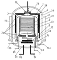
図1は本発明の加熱装置の断面図である。なお、本図において図2と共通の部分については同一の符号を付してあり、重複した説明は省略する。本発明の加熱装置は内部に被加熱物5を収容する密閉竪型円筒状で底部が開放可能で水蒸気を含む気体が導入される反応容器1と、該反応容器1に上から被せるように囲繞する下方が開放された竪型円筒状のヒータ容器2と、これらの容器を収容する竪型円筒状で底部が開放可能な耐圧密閉容器3とを有してなる。上記反応容器1は、上部が皿形で密閉され下部が開放された円筒状で下端に外側に張り出したフランジを有する上部構造1aと、上部が皿形で密閉され下部が開放された円筒状で下端に外側に張り出したフランジを有し、高さが上記上部構造1aより低く、上部構造内に下から挿入される底部構造1bと、上記上部構造1aのフランジと上記底部構造1bのフランジとに挟まれたシール1cとからなり、上記底部構造1bの外周と上記上部構造1aの内周との間に形成されるシール1c内側の隙間15に、注水配管13aと排水配管13bとを接続したものである。なお、14は隙間15に溜った水であり、16は熱放散蓋である。熱放散蓋16は、ヒータ容器16の天井部に設けられた孔2bを塞ぐようになっていて、加熱が完了して被加熱物5を自然冷却するときに開放して密閉容器3内の対流循環を活発に行わせて、被加熱物の冷却を促進するために設けられている。
【0013】
次に本実施形態の作用を説明する。
被加熱物5を反応容器1内に収容し、ヒータ2aにより加熱を始める前に底部構造1bの外周と上部構造1aの内周との間に形成されるシール1c内側の隙間15に注水して水14を溜めておく。ヒータ2aによる加熱で反応容器1内部は600℃程度の加熱温度まで昇温するが、この隙間15の部分は、ヒータ2aにより加熱されておらず、反応容器1壁面からの伝熱のみなので注水された部分14への入熱量は小さい。反応容器1が加熱温度に保たれている間に、この隙間に溜った水14は蒸発するので注水配管13aを通じて水を補給する。反応容器1内には酸化ガスとして水蒸気が導入されており、水蒸気分圧が高いので、上記隙間15に溜った水14の蒸発量は少い。蒸発により潜熱が奪われるので水の温度は、反応容器内の水蒸気分圧に相当する飽和温度よりも高くなることはなく、シール1cの耐熱温度以下におさまる。また、この隙間15に水を溜めてあるので、反応容器1内に導入した水蒸気が低温部で結露する量を低減することができる。
【0014】
本発明は以上述べた実施形態に限定されるものではなく、発明の要旨を逸脱しない範囲で種々の変更が可能である。
【0015】
【発明の効果】
以上説明したように、本発明の加熱装置は反応容器の底部構造の外周と上部構造の内周との間に形成される隙間に注、排水配管を接続し、反応容器の加熱中には上記隙間に水を溜めるようにしたので、反応容器の上部構造と底部構造との間のシールが過熱されて劣化することがなく信頼性が向上するとともに、反応容器内部に導入された水蒸気が低温部で結露する量を低減することができるなどの優れた効果を有する。
【図面の簡単な説明】
【図1】本発明の加熱装置の断面図である。
【図2】従来の加熱装置の断面図である。
【符号の説明】
1 反応容器
1a 上部構造
1b 底部構造
1c シール
2 ヒータ容器
3 密閉容器
5 被加熱物
13a 注水配管
13b 排水配管
15 隙間[0001]
[Technical field to which the invention belongs]
The present invention relates to a heating device used for heat treatment of a semiconductor or the like, and more particularly to a heating device used for heat treatment of a thin film transistor formed on a glass substrate in order to manufacture a liquid crystal display, an image sensor, or the like.
[0002]
[Prior art]
Conventionally, heating furnaces such as annealing furnaces, diffusion furnaces, oxidation furnaces and low-pressure CVD (Chemical Vapor Deposition) for forming semiconductor films formed on silicon wafers and substrates have been used. . In recent years, these heating furnaces are mainly of a type in which a reaction tube is placed vertically instead of a type in which a reaction tube is placed horizontally (for example, disclosed in FIG. 3 of JP-A-8-8194) in order to save the space of the apparatus. It has become. Further, in an oxidation furnace, a high reaction rate depending on the pressure can be obtained by increasing the gas atmosphere in the reaction tube (for example, disclosed in JP-A-53-112064 and JP-A-56-24938). .) Is also known. In recent years, since a large-area square glass substrate is used for a liquid crystal display or the like, an apparatus for processing a large-area square glass substrate is required instead of the conventional round silicon wafer.
[0003]
Moreover, when processing a glass substrate, it is necessary to process at the temperature which does not affect a glass substrate. Usually, alkali-free glass is used in consideration of the influence of impurities on the semiconductor device. As the alkali-free glass, barium borosilicate glass, borosilicate glass, aluminoborosilicate glass, aluminosilicate glass, or the like is used. However, the strain point of such a glass substrate is about 593 to 700 ° C., and the actually usable temperature is 600 ° C. or less. In addition, the reactor body of the reaction vessel is made of quartz or the like to prevent internal contamination, and in order to increase the pressure in the reaction vessel, the reaction vessel is housed in a steel sealed vessel that can withstand high pressure, The pressure inside and outside the reaction vessel is made equal.
[0004]
FIG. 2 is a cross-sectional view of a conventional heating device. In the figure, reference numeral 1 denotes a reaction vessel having a closed bowl-shaped cylindrical shape that accommodates an object to be heated and whose bottom can be opened. As described above, the reaction vessel 1 is made of quartz or the like, and is composed of an upper structure 1a and a
[0005]
3 is an airtight container. The hermetic container 3 is a pressure vessel made of steel and includes an
[0006]
[Problems to be solved by the invention]
Since the seal 1c sandwiched between the flange of the upper structure 1a and the flange of the
[0007]
However, the cooling by the
[0008]
The present invention has been devised in view of such problems of the prior art and based on the above knowledge, and provides a heating device that does not require the
[0009]
[Means for Solving the Problems]
In order to achieve the above object, the heating device of the present invention includes a sealed bowl-shaped cylindrical shape that accommodates an object to be heated, a bottom that can be opened and a gas containing water vapor introduced thereinto, and the reaction container from above. A heating apparatus comprising a vertical cylindrical heater container that is open at the bottom to be covered and a vertical cylindrical container that accommodates these containers and that can be opened at the bottom, The reaction vessel has a cylindrical structure with the upper part sealed and the lower part open and has a flange projecting outward at the lower end, and a cylindrical structure with the upper part sealed and the lower part opened, and a flange projecting outward at the lower end. A lower structure inserted from below into the upper structure, and a seal sandwiched between the flange of the upper structure and the flange of the lower structure, and the outer periphery of the bottom structure And the superstructure The seal inside the gap formed between the inner periphery which are connected Note, the discharge pipe.
[0010]
It is preferable that a gas of 1 to 50 atm is enclosed in the reaction vessel and the sealed vessel.
[0011]
Next, the operation of the present invention will be described.
An object to be heated is accommodated in a reaction vessel, and water is poured into a gap inside the seal formed between the outer periphery of the bottom structure and the inner periphery of the upper structure before heating by the heater is started. Although the inside of the reaction vessel is heated up to the heating temperature by heating with the heater, the gap portion is not heated by the heater, and only heat transfer from the wall surface of the reaction vessel makes the amount of heat input to the injected portion small. While the reaction vessel is kept at the heating temperature, the water accumulated in this gap evaporates, so water is replenished. Water vapor is introduced as an oxidizing gas into the reaction vessel, and the partial pressure of water vapor is high, so that the amount of water accumulated in the gap is small. Since latent heat is taken away by evaporation, the temperature of water does not become higher than the saturation temperature corresponding to the water vapor partial pressure in the reaction vessel, and is kept below the heat resistant temperature of the seal. Further, since water is accumulated in the gap, it is possible to reduce the amount of water vapor introduced into the reaction vessel at the low temperature portion.
[0012]
DETAILED DESCRIPTION OF THE INVENTION
Hereinafter, an embodiment of the present invention will be described with reference to the drawings.
FIG. 1 is a cross-sectional view of the heating apparatus of the present invention. In this figure, parts common to those in FIG. 2 are denoted by the same reference numerals, and redundant description is omitted. The heating device of the present invention has a sealed bowl-shaped cylindrical shape that accommodates an object to be heated 5 therein, a reaction vessel 1 that can be opened at the bottom and introduced with a gas containing water vapor, and an enclosure that covers the reaction vessel 1 from above. A vertical
[0013]
Next, the operation of this embodiment will be described.
The object to be heated 5 is accommodated in the reaction vessel 1, and water is poured into a
[0014]
The present invention is not limited to the embodiments described above, and various modifications can be made without departing from the scope of the invention.
[0015]
【The invention's effect】
As described above, the heating device of the present invention is poured into the gap formed between the outer periphery of the bottom structure of the reaction vessel and the inner periphery of the upper structure, connected to the drainage pipe, and during the heating of the reaction vessel, Since water is stored in the gap, the seal between the upper structure and the bottom structure of the reaction vessel is not overheated and deteriorated, and the reliability is improved. It has excellent effects such as being able to reduce the amount of condensation.
[Brief description of the drawings]
FIG. 1 is a cross-sectional view of a heating apparatus according to the present invention.
FIG. 2 is a cross-sectional view of a conventional heating device.
[Explanation of symbols]
DESCRIPTION OF SYMBOLS 1 Reaction container 1a
Claims (5)
Priority Applications (1)
| Application Number | Priority Date | Filing Date | Title |
|---|---|---|---|
| JP13235499A JP3874152B2 (en) | 1999-05-13 | 1999-05-13 | Heating apparatus and heating method |
Applications Claiming Priority (1)
| Application Number | Priority Date | Filing Date | Title |
|---|---|---|---|
| JP13235499A JP3874152B2 (en) | 1999-05-13 | 1999-05-13 | Heating apparatus and heating method |
Publications (3)
| Publication Number | Publication Date |
|---|---|
| JP2000323419A JP2000323419A (en) | 2000-11-24 |
| JP2000323419A5 JP2000323419A5 (en) | 2005-10-27 |
| JP3874152B2 true JP3874152B2 (en) | 2007-01-31 |
Family
ID=15079408
Family Applications (1)
| Application Number | Title | Priority Date | Filing Date |
|---|---|---|---|
| JP13235499A Expired - Fee Related JP3874152B2 (en) | 1999-05-13 | 1999-05-13 | Heating apparatus and heating method |
Country Status (1)
| Country | Link |
|---|---|
| JP (1) | JP3874152B2 (en) |
Families Citing this family (4)
| Publication number | Priority date | Publication date | Assignee | Title |
|---|---|---|---|---|
| JP2006165304A (en) * | 2004-12-08 | 2006-06-22 | Ishikawajima Harima Heavy Ind Co Ltd | Vapor anneal device and vapor introduction method therein |
| JP5024645B2 (en) * | 2005-07-07 | 2012-09-12 | 株式会社Ihi | Steam annealing jig |
| JP4683332B2 (en) * | 2005-12-28 | 2011-05-18 | 株式会社Ihi | Heat treatment equipment |
| JP2010021558A (en) * | 2009-07-23 | 2010-01-28 | Kyoshin Engineering:Kk | High precision and high pressure annealing apparatus |
-
1999
- 1999-05-13 JP JP13235499A patent/JP3874152B2/en not_active Expired - Fee Related
Also Published As
| Publication number | Publication date |
|---|---|
| JP2000323419A (en) | 2000-11-24 |
Similar Documents
| Publication | Publication Date | Title |
|---|---|---|
| JP3007432B2 (en) | Heat treatment equipment | |
| JP3164248B2 (en) | Heat treatment equipment | |
| US5318633A (en) | Heat treating apparatus | |
| JP2021184462A (en) | Flange and apparatus for processing substrates | |
| JP4985449B2 (en) | Deposition equipment | |
| JP3874152B2 (en) | Heating apparatus and heating method | |
| JPH06204231A (en) | Semiconductor heat treatment device | |
| JP4063661B2 (en) | Semiconductor manufacturing apparatus and semiconductor manufacturing method | |
| JPH11354515A (en) | Pressure type heating furnace | |
| KR100793836B1 (en) | Vacuum apparatus using liquidnitrogen | |
| JPH04306824A (en) | Heat treatment device | |
| JP3493530B2 (en) | Heat treatment equipment | |
| JP2691159B2 (en) | Vertical heat treatment equipment | |
| JP3690095B2 (en) | Deposition method | |
| JP3055797B2 (en) | Vertical heat treatment equipment | |
| JP3791657B2 (en) | High pressure heating apparatus and high pressure heating method | |
| JP2006097080A (en) | Substrate treatment device | |
| JP3070567B2 (en) | Vertical reduced pressure vapor phase growth apparatus and vapor phase growth method using the same | |
| JP3874151B2 (en) | Heating device | |
| JP3328853B2 (en) | Heat treatment apparatus and heat treatment method | |
| JP3056240B2 (en) | Heat treatment equipment | |
| JP2000058459A (en) | Thermal treatment method and thermal treatment equipment | |
| JP2000068260A (en) | Heat-treating apparatus | |
| JPH10231932A (en) | Sealing device | |
| JP4364962B2 (en) | Substrate processing apparatus and substrate processing method |
Legal Events
| Date | Code | Title | Description |
|---|---|---|---|
| A521 | Written amendment |
Free format text: JAPANESE INTERMEDIATE CODE: A523 Effective date: 20050712 |
|
| A621 | Written request for application examination |
Free format text: JAPANESE INTERMEDIATE CODE: A621 Effective date: 20050712 |
|
| A977 | Report on retrieval |
Free format text: JAPANESE INTERMEDIATE CODE: A971007 Effective date: 20060602 |
|
| A131 | Notification of reasons for refusal |
Free format text: JAPANESE INTERMEDIATE CODE: A131 Effective date: 20060725 |
|
| A521 | Written amendment |
Free format text: JAPANESE INTERMEDIATE CODE: A523 Effective date: 20060920 |
|
| TRDD | Decision of grant or rejection written | ||
| A01 | Written decision to grant a patent or to grant a registration (utility model) |
Free format text: JAPANESE INTERMEDIATE CODE: A01 Effective date: 20061005 |
|
| A61 | First payment of annual fees (during grant procedure) |
Free format text: JAPANESE INTERMEDIATE CODE: A61 Effective date: 20061018 |
|
| S533 | Written request for registration of change of name |
Free format text: JAPANESE INTERMEDIATE CODE: R313533 |
|
| FPAY | Renewal fee payment (event date is renewal date of database) |
Free format text: PAYMENT UNTIL: 20091102 Year of fee payment: 3 |
|
| R350 | Written notification of registration of transfer |
Free format text: JAPANESE INTERMEDIATE CODE: R350 |
|
| FPAY | Renewal fee payment (event date is renewal date of database) |
Free format text: PAYMENT UNTIL: 20091102 Year of fee payment: 3 |
|
| FPAY | Renewal fee payment (event date is renewal date of database) |
Free format text: PAYMENT UNTIL: 20101102 Year of fee payment: 4 |
|
| FPAY | Renewal fee payment (event date is renewal date of database) |
Free format text: PAYMENT UNTIL: 20111102 Year of fee payment: 5 |
|
| FPAY | Renewal fee payment (event date is renewal date of database) |
Free format text: PAYMENT UNTIL: 20121102 Year of fee payment: 6 |
|
| FPAY | Renewal fee payment (event date is renewal date of database) |
Free format text: PAYMENT UNTIL: 20131102 Year of fee payment: 7 |
|
| LAPS | Cancellation because of no payment of annual fees |