JP3871347B2 - Enhancing Primitive Coding Using Spectral Band Replication - Google Patents
Enhancing Primitive Coding Using Spectral Band Replication Download PDFInfo
- Publication number
- JP3871347B2 JP3871347B2 JP50196299A JP50196299A JP3871347B2 JP 3871347 B2 JP3871347 B2 JP 3871347B2 JP 50196299 A JP50196299 A JP 50196299A JP 50196299 A JP50196299 A JP 50196299A JP 3871347 B2 JP3871347 B2 JP 3871347B2
- Authority
- JP
- Japan
- Prior art keywords
- signal
- subband
- frequency
- signals
- segment
- Prior art date
- Legal status (The legal status is an assumption and is not a legal conclusion. Google has not performed a legal analysis and makes no representation as to the accuracy of the status listed.)
- Expired - Lifetime
Links
Images


Classifications
-
- G—PHYSICS
- G10—MUSICAL INSTRUMENTS; ACOUSTICS
- G10L—SPEECH ANALYSIS OR SYNTHESIS; SPEECH RECOGNITION; SPEECH OR VOICE PROCESSING; SPEECH OR AUDIO CODING OR DECODING
- G10L21/00—Processing of the speech or voice signal to produce another audible or non-audible signal, e.g. visual or tactile, in order to modify its quality or its intelligibility
- G10L21/02—Speech enhancement, e.g. noise reduction or echo cancellation
- G10L21/038—Speech enhancement, e.g. noise reduction or echo cancellation using band spreading techniques
-
- H—ELECTRICITY
- H04—ELECTRIC COMMUNICATION TECHNIQUE
- H04B—TRANSMISSION
- H04B1/00—Details of transmission systems, not covered by a single one of groups H04B3/00 - H04B13/00; Details of transmission systems not characterised by the medium used for transmission
- H04B1/66—Details of transmission systems, not covered by a single one of groups H04B3/00 - H04B13/00; Details of transmission systems not characterised by the medium used for transmission for reducing bandwidth of signals; for improving efficiency of transmission
- H04B1/667—Details of transmission systems, not covered by a single one of groups H04B3/00 - H04B13/00; Details of transmission systems not characterised by the medium used for transmission for reducing bandwidth of signals; for improving efficiency of transmission using a division in frequency subbands
Landscapes
- Engineering & Computer Science (AREA)
- Signal Processing (AREA)
- Acoustics & Sound (AREA)
- Multimedia (AREA)
- Health & Medical Sciences (AREA)
- Audiology, Speech & Language Pathology (AREA)
- Human Computer Interaction (AREA)
- Physics & Mathematics (AREA)
- Computational Linguistics (AREA)
- Quality & Reliability (AREA)
- Computer Networks & Wireless Communication (AREA)
- Compression, Expansion, Code Conversion, And Decoders (AREA)
- Luminescent Compositions (AREA)
- Pyridine Compounds (AREA)
- Reduction Or Emphasis Of Bandwidth Of Signals (AREA)
- Spectrometry And Color Measurement (AREA)
- Cosmetics (AREA)
Abstract
Description
技術分野
原始コーディング装置では、必要なビットレートや記憶容量を減らすためにディジタルデータを圧縮して伝送または記憶する。本発明は、スペクトル帯域複製(SBR)により原始コーディング(source coding)を改善する新規な方法と装置に関するものである。同じ知覚品質を保持してビットレートを実質的に下げ、逆に所定のビットレートで知覚品質を高める。これは、エンコーダ側でスペクトル帯域幅を縮小し、デコーダ側で後のスペクトル帯域を複製することにより行う。本発明はスペクトル領域での信号冗長度の新しい概念を活用する。
発明の背景
オーディオ原始コーディング技術は2種類ある。すなわち、自然オーディオコーディングと音声コーディングである。自然オーディオコーディングは中位のビットレートの音楽や任意の信号に共通に用いられており、オーディオ帯域幅は一般に広い。音声コーダは基本的に音声の再生に限られるが、他方では非常に低いビットレートで用いることができる。ただしオーディオ帯域幅は狭い。広帯域音声は狭帯域音声に比べて主な主観的品質が優れている。帯域幅を広くすると、音声の明瞭度と自然さが増すだけでなく、話す人を識別しやすくなる。このように広帯域音声コーディングは次世代電話システムにとって重要な課題である。更に、マルチメディア分野が非常に成長したので、音楽や非音声信号を電話システムにより高品質で伝送することが望ましい。
高忠実度の線形PCM信号は、ビットレート対知覚エントロピーに関して非常に効率が悪い。CDの標準は44.1kHzのサンプリング周波数と、サンプル当たり16ビットの分解能と、ステレオである。これは1411キロビット/sのビットレートに等しい。ビットレートを大幅に下げるため、分割帯域知覚オーディオコーデックを用いて原始コーディングを行うことができる。これらの自然オーディオコーデックは信号内の知覚無関係性と統計的冗長度を用いる。最高のコーデック技術を用いると、標準のCDフォーマット信号のデータを約90%縮小しても実際上は劣化したと感じない。このように、ステレオでは約96キロビット/s、すなわち約15:1の圧縮率で、非常に高い音質が得られる。或る知覚コーデックは更に高い圧縮率を用いる。このためには、サンプリングレート(したがってオーディオ帯域幅)を下げるのが普通である。また量子化レベルの数を減らし(量子化歪みが聞こえることがある)、また強化コーディングによるステレオフィールドの劣化を用いるのが普通である。このような方法を余り用いると、耳障りな知覚劣化を生じる。現在のコーデック技術は飽和点に近く、符号化利得が更に進むことは期待できない。符号化性能を高めるには、新しい方式が必要である。
人の声や殆どの楽器は、振動システムから発生する準定常信号を生成する。フーリエ理論によると、周期的信号は周波数f、2f、3f、4f、5fなどの正弦波の和で表される。ただし、fは基本周波数である。これらの周波数は調波系列を形成する。この信号の帯域幅を制限することは、調波系列を切り捨てることに相当する。切捨てを行うと楽器や音声の音色が変わり、オーディオ信号は「弱い」または「鈍い」音になり、明瞭度が下がる。音質の主観的印象にとって高周波はこのように重要である。
従来の方法は、音声コーデック性能を高めることが主体で、特に音声符号化における問題である高周波再生(HFR)を目的としている。従来の方法は広帯域直線周波数シフトや、非線形性や、エイリアシングを用いて[米国特許番号第5,127,054号]相互変調やその他の非調波周波数成分を生成するので、これを音楽信号に適用するとひどい不協和音を生じた。この不協和音を音声符号化関係の文献では「耳障り」または「調子はずれ」の音と呼ぶ。他の合成音声HFR法は基本ピッチ推定に基づく正弦高調波を生成するので、定常音に限られる[米国特許番号第4,771,465号]。これらの従来の方法は低品質の音声応用には有用であるが、高品質音声または音楽信号には使えない。高品質のオーディオ原始コーデックの性能を高める方法がいくつかある。その1つは、デコーダで生成された合成雑音信号を用いて、以前はエンコーダで捨てられていた音声または音楽内の雑音的信号に代える(「雑音代替によるオーディオコーデックの改善(Improving Audio Codecs by Noise Substitution)」、D. Schulz, JAES, Vol. 44, No. 7/8, 1996)。これは雑音信号があるときに、本来正常に伝送される高帯域内で断続的に行われる。別の方法は、符号化の過程で失われた或る高帯域の高調波を再現する(「オーディオスペクトルコーダ(Audio Spectral Coder)」、A. J. S. Ferreira, AES Preprint 4201, 100th Convention, May 11-14, 1996, Copenhagen)。これも音信号とピッチ検出に依存する。この2つの方法は低いデューティサイクルで動作し、比較的限定された符号化または性能の利得が得られる。
発明の概要
本発明はディジタル原始コーディング装置を実質的に改善する、より特定するとオーディオコーデックを改善する、新しい方法と装置を提供する。目的は、ビットレートの低下、または知覚品質の向上、またはその両方を含む。本発明は調波冗長度を活用した新しい方法により、伝送または記憶を行う前に信号の通過帯域を廃棄する可能性を提供する。本発明によりデコーダが高品質のスペクトル複製を行う場合は、知覚劣化は起こらない。廃棄ビットは一定の知覚品質における符号化利得を表す。または、一定のビットレートにおいて低帯域情報の符号化に更に多くのビットを割り当てて、より高い知覚品質を得ることができる。
本発明は、廃棄された調波系列は低帯域スペクトル成分と高帯域スペクトル成分の間の直接の関係に基づいて伸張することができると仮定する。この伸張された系列は、次の規則に従っていれば初めの系列と似ていると知覚される。第1に、不協和音に関係する人工音が出ないようにするために、外挿されるスペクトル成分は廃棄された調波系列と調波的に関係していなければならない。本発明はスペクトル複製プロセスの手段として置換を用いる。これは確かにこの判定基準を満たす。しかし優れた動作をするためには低帯域スペクトル成分が調波系列を形成する必要はない。その理由は、低帯域成分と調波的に関係する新しい複製成分は信号の雑音的または過渡的な性質を変えないからである。置換とは、部分音の周波数比を保ちながら部分音を音階上の1つの位置から別の位置に移すことである。第2に、複製された高帯域のスペクトル包絡線(すなわち、粗いスペクトル分布)は初めの信号と十分似ていなければならない。本発明は2つの動作モードSBR−1とSBR−2を提供する。この2つは、スペクトル包絡線を調整する方法が異なる。
SBR−1は中間品質コーデック応用を改善するシングルエンド形のプロセスであって、デコーダが受ける低帯域信号すなわち低域信号に含まれる情報に完全に依存する。この信号のスペクトル包絡線は、例えば多項式と規則の集合すなわちコードブックを用いて決定され、外挿される。この情報を用いて、複製された高帯域を絶えず調整し等化する。このSBR−1法は後処理の利点を持つ。すなわちエンコーダ側では修正する必要がない。放送業者はチャンネルの利用度を高め、または知覚品質を高め、またはその両者が得られる。既存のビットストリーム構文と標準を修正せずに用いることができる。
SBR−2は高品質コーデック応用を改善するダブルエンド形のプロセスであって、SBR−1により伝送される低帯域信号の他に、高帯域のスペクトル包絡線を符号化して伝送する。スペクトル包絡線の変動速度は高帯域信号成分よりかなり低いので、限られた量の情報だけを伝送すればスペクトル包絡線を十分表すことができる。SBR−2を用いれば、既存の構文やプロトコルを全くまたは殆ど修正せずに現在のコーデック技術の性能を高めることができるので、今後のコーデックの開発の貴重なツールである。
SBR−1もSBR−2も、音響心理学モデルにより規定されたエンコーダがビット欠乏状態の下で低帯域の小さな通過帯域を停止したとき、これらを複製するのに用いられる。低帯域内のスペクトル複製と低帯域外のスペクトル複製により、知覚品質が高まる。更に、SBR−1とSBR−2はビットレートスケーラビリティを用いるコーデックにも用いることができる。この場合、受信器での信号の知覚品質は伝送チャンネルの状態によって変わる。通常は、これは受信器でのオーディオ帯域幅の厄介な変動を意味する。この状態でSBR法を用いると常に高い帯域幅を保持するので、やはり知覚品質を高めることができる。
本発明は連続的に動作し、どんな種類の信号内容、すなわち音または非音(雑音的信号や過渡信号)も複製する。更に、本発明のスペクトル複製法はデコーダで利用できる周波数帯域から、廃棄された帯域を知覚的に正確に複製することができる。したがってSBR法を用いると、従来の方法に比べて実質的に高いレベルで符号化利得が得られ、または知覚品質を高めることができる。本発明を従来のコーデック改善法と組み合わせることはできるが、組み合わせても性能が高まることは期待できない。
SBR法は次のステップを含む。
・ 初めの信号から得た信号を符号化し、信号の周波数帯域を廃棄する。廃棄は符号化の前か途中に行い、第1信号を形成する。
・ 第1信号の復号中またはその後で、第1信号の周波数帯域を置換して第2信号を形成する。
・ スペクトル包絡線を調整する。
・ 復号された信号と第2信号を組み合わせて出力信号を形成する。
第2信号の通過帯域は第1信号の通過帯域と重ならないようにまたは部分的に重なるように設定してよく、初めの信号および/または第1信号の時間特性、または伝送チャンネルの状態に従って設定する。スペクトル包絡線の調整は、前記第1信号から初めのスペクトル包絡線を推定したもの、または初めの信号の伝送された包絡線情報に基づいて行う。
本発明は2つの基本型のトランスポーザ(置換装置)を含む。すなわち、多帯域トランスポーザと時変パターン探索予測トランスポーザであって、これらは異なる特性を有する。本発明では基本的な多帯域置換を次のように行う。
・ 置換される信号を、それぞれ周波数[f1,...,fN]を含む通過帯域を持つN(≧2)個の通過帯域フィルタの集合で濾波して、N個の帯域信号を形成する。
・ 帯域信号の周波数を周波数M[f1,...,fN]を含む領域にシフトする。ただし、M≠1は置換係数である。
・ シフトされた帯域信号を結合して置換信号を形成する。
または、本発明ではこの基本的多帯域置換を次のように行う。
・ 置換される信号を、低域型の実数値または複素値サブバンド信号を生成する性質の分析フィルタバンクまたは変換を用いて帯域濾波する。
・ 任意のチャンネル数kの前記分析フィルタバンクまたは変換を、合成フィルタバンクまたは変換内のMk(M≠1)チャンネルに接続する。
・ 合成フィルタバンクまたは変換を用いて、置換された信号を形成する。
本発明の1つの改善された多帯域置換は位相調整を含み、基本的な多帯域置換の性能を強化する。
本発明では時変パターン探索予測置換を次のように行う。
・ 第1信号の過渡検出を行う。
・ 過渡検出の結果に従って、第1信号の一部を複写/廃棄するときに、第1信号のどのセグメントを用いるかを決定する。
・ 過渡検出の結果に従って、状態ベクトルとコードブック特性を調整する。
・ 前の同期点探索で見出された同期点に基づいて、第1信号の選択されたセグメント内の同期点を探す。
本発明のSBR法は次の特徴を有する。
1. この方法と装置はスペクトル領域内の信号冗長性の新しい概念を活用する。
2. この方法と装置は任意の信号に適用することができる。
3. 各調波集合は個々に作成して制御することができる。
4. 全ての複製された高調波は既存の調波系列の延長を形成するようにして生成する。
5. スペクトル複製プロセスは置換に基づくもので、人工音は全くまたは殆ど知覚されない。
6. スペクトル複製は多数の小帯域および/または広い周波数範囲をカバーすることができる。
7. SBR−1法では、処理はデコーダ側だけで行う。すなわち、全ての標準およびプロトコルを修正せずに用いることができる。
8. SBR−2法は修正を全くまたは殆どせずに、殆どの標準やプロトコルに従って実現することができる。
9. SBR−2法はコーデック設計者に新しい強力な圧縮ツールを提供する。
10. 符号化利得は顕著である。
最も魅力的な応用は、各種の低ビットレートコーデック、例えば、MPEG1/2層I/II/III[米国特許番号第5,040,217号]や、MPEG2/4 AAC、Dolby AC−2/3、NTT TwinVQ[米国特許番号第5,684,920号]や、AT&T/Lucent PACなど、の改善に関する。。またこの発明は知覚品質を高めるための、高帯域CELPやSB−ADPCM G.722などの、高品質音声コーデックにも有用である。上記のコーデックはマルチメディアや、電話産業や、インターネットや、専門的な応用に広く用いられている。T−DAB(地上ディジタルオーディオ放送)システムは低ビットレートプロトコルを用いており、本方法を用いるとチャンネル使用度が上がり、またはFMやAM DABの品質を高めることができる。衛星S−DABはシステムコストが非常に高いので、本方法を用いてDABマルチプレクスのプログラムチャンネル数を増やすことにより大きな利益を得る。更に、低ビットレート電話モデムを用いて、インターネットにより初めて全帯域幅オーディオ実時間ストリーミングを達成することができる。
【図面の簡単な説明】
以下に本発明について添付の図面を参照して例を用いて説明するが、これは本発明の範囲や精神を制限するものではない。
図1は、本発明の符号化装置内に挿入されたSBRである。
図2は、本発明の上部高調波のスペクトル複製を示す。
図3は、本発明の帯域内高調波のスペクトル複製を示す。
図4は、本発明のトランスポーザの時間領域実現のブロック図である。
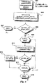
図5は、本発明のパターン探索予測トランスポーザの動作のサイクルを表す流れ図である。
図6は、本発明の同期点の探索を表す流れ図である。
図7a−図7bは、本発明の過渡状態中のコードブック位置決めを示す。
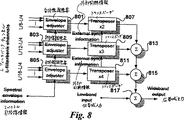
図8は、本発明のSBR動作のための、適当なフィルタバンクに関するいくつかの時間領域トランスポーザの実現のブロック図である。
図9a−図9cは、2次高調波を生成するよう構成された本発明のSTFT分析および合成用の装置を表すブロック図である。
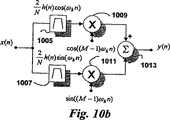
図10a−図10bは、本発明のSTFT装置内の直線周波数シフトを持つ1つのサブバンドのブロック図である。
図11は、本発明の位相乗算器を用いる1つのサブバンドを示す。
図12は、本発明の3次高調波を生成する方法を示す。
図13は、本発明の2次および3次高調波を同時に生成する方法を示す。
図14は、本発明のいくつかの次数の高調波の重ならない組合わせの生成を示す。
図15は、本発明のいくつかの次数の高調波の交互配置組合わせの生成を示す。
図16は、高帯域の直線周波数シフトの生成を示す。
図17は、本発明の分数調波を生成する方法を示す。
図18a−図18bは、知覚コーデックのブロック図である。
図19は、最大10進化フィルタバンクの基本構造を示す。
図20は、本発明の最大10進化フィルタバンクの2次高調波の生成を示す。
図21は、本発明のサブバンド信号上で動作する最大10進化フィルタバンク内の改善された多帯域置換のブロック図である。
図22は、本発明のサブバンド信号上で動作する最大10進化フィルタバンク内の改善された多帯域置換を表す流れ図である。
図23は、一般的なコーデックのサブバンドサンプルと換算係数を示す。
図24は、本発明のSBR−2用のサブバンドサンプルと包絡線情報を示す。
図25は、本発明のSBR−2内の包絡線の隠された伝送を示す。
図26は、本発明のSBR−2内の冗長度符号化を示す。
図27は、本発明のSBR−1法を用いたコーデックの実現を示す。
図28は、本発明のSBR−2法を用いたコーデックの実現を示す。
図29は、本発明の「疑似ステレオ」発生器のブロック図である。
好ましい実施の形態の説明
実施の形態の説明を通じて、自然オーディオ原始コーディング応用に重点を置いて述べる。しかし理解されるように、本発明はオーディオ信号の符号化や復号の応用の他に広範囲の原始コーディング応用に適用できるものである。
置換の基礎
本発明で述べる置換はスペクトル複製の理想的な方法であって、従来の方法に比べていくつかの大きな利点を持つ。すなわち、ピッチ検出は必要なく、単一ピッチで多音のプログラム材料において同じ高性能が得られ、置換は音信号にも非音信号にも同じように良く適用できる。他の方法とは異なり、本発明の置換は任意の信号の種類において任意のオーディオ原始コーディング装置に用いることができる。
時変振幅を持つコサインの和の形の離散時間信号x(n)の正確な置換係数Mは、次の関係で定義される。

図2にM次高調波の生成を示す。ただし、Mは整数≧2である。M次高調波という語は簡単のために用いた。実際は、このプロセスは或る周波数領域で全ての信号にM次高調波を生成するが、多くの場合は次数の分からない高調波である。周波数領域の表現X(f)を持つ入力信号201の帯域は0からfmaxの範囲に限定される。fmax/MからQfmax/M(Qは望ましい帯域幅伸張係数で1<Q≦M)の範囲内の信号内容を帯域フィルタで取り出して、スペクトルXBP(f)を持つ帯域信号203を形成する。帯域信号を係数Mで置換して、fmaxからQfmaxの範囲をカバーするスペクトルXT(f)を持つ第2帯域信号205を形成する。この信号のスペクトル包絡線をプログラム制御の等化器で調整して、スペクトルXE(f)を持つ信号207を形成する。次にこの信号と遅延させた入力信号とを結合して、帯域フィルタとトランスポーザにより生じる遅れを補償して、0からQfmaxの範囲をカバーするスペクトルY(f)を持つ出力信号209を形成する。または帯域濾波は、遮断周波数fmaxとQfmaxを用いて置換Mの後で行う。多重トランスポーザを用いて、異なる調波次数を同時に生成することはもちろん可能である。図3に示すように入力信号がf0からQf0にわたる通過帯域301を有する場合、上記の方式を用いて入力信号内の通過帯域を「充填する」こともできる。この場合は通過帯域[f0/M,Qf0/M]を取り出し(303)、係数Mで[f0,Qf0]に置換し(305)、包絡線を調整し(307)、遅延入力信号と結合してスペクトルY(f)を持つ出力信号309を形成する。
正確な置換の近似を用いてもよい。本発明では、このような近似の質を不協和音理論を用いて決定する。不協和音の判定基準はPlompにより示されており[「音の協和と臨界帯域幅(Tonal Consonance and Critical Bandwidth)」、R. Plomp, W. J. M. Levelt JASA, Vol. 38, 1965]、2つの部分音の周波数の差がそれらが存在する臨界帯域の帯域幅の約5乃至50%以内である場合は、2つの部分音は不協和と見なされる。例えば、所定の周波数の臨界(critical)帯域幅は次式で近似できる。
![]()
![]()
本発明のスペクトル複製法に基づく上記の置換を用いると、次の重要な性質が得られる。
・ 通常は、複製された高調波と既存の部分音の間に周波数領域の重なりが起こらない。
・ 複製された部分音は入力信号の部分音と調波的に関係があり、耳障りな不協和音すなわち人工音を一切生じない。
・ 複製された高調波のスペクトル包絡線は入力信号スペクトル包絡線の滑らかな継続を形成し、初めの包絡線と知覚的に一致する。
時変パターン探索予測に基づく置換
必要なトランスポーザを設計するには種々の方法がある。一般的な時間領域実現では、ピッチ周期に基づいて信号セグメントを複製することにより信号を時間的に伸張する。次にこの信号を異なる速度で読み出す。残念ながらこの方法は、信号セグメントを正確に時間接続するのにピッチ検出に厳密に依存する。更に、ピッチ周期に基づく信号セグメントには制約があるので、過渡信号に敏感になる。検出されたピッチ周期は実際の過渡信号よりかなり長いことがあるので、全過渡信号を単に時間的に伸張するのではなく複写するという危険が大きいことは明らかである。別の種類の時間領域アルゴリズムでは、出力信号のパターン探索予測を用いて音声信号の時間伸張/圧縮を得る[「音声のパターン探索予測(Pattern Search Prediction of Speech)」、R. Bogner, T. Li, Proc. ICASS,'89, Vol. 1, May 1989や、「非線形発振器モデルに基づく音声のタイムスケール修正(Time-Scale Modification of Speech based on a nonlinear Oscillator Model)」、G. Kubin, W. B. Kleijin, IEEE, 1994]。これは粒状合成(granular synthesis)の1つの形であって、入力信号を小さな部分(細粒)に分割し、これを用いて出力信号を合成する。この合成には通常は信号セグメントの相関を取って、最良の接続点を決定する。これは、出力信号を形成するのに用いるセグメントがピッチ周期に依存しないのでピッチ検出という厄介なタスクを必要としないことを意味する。しかしこの方法にも信号振幅が急速に変わるときの問題がまだあり、高品質の置換のためには高速計算が必要になる。しかし改善された時間領域のピッチシフタ/トランスポーザをここに提示する。この方式は過渡検出と動的システムパラメータを用いることにより、定常音(音または非音)でも過渡音でも、高い置換係数の一層正確な置換を低い計算コストで行うことができる。
次に図面を参照する。各図面の同じ要素は同じ番号で示す。図4に9個の別個のモジュールを示す。すなわち、過渡検出器401と、窓位置調整器403と、コードブック発生器405と、同期信号選択器407と、同期位置メモリ409と、最小差推定器411と、出力セグメントメモリ413と、混合ユニット415と、ダウンサンプラ417である。入力信号はコードブック発生器405と過渡検出器401に入る。過渡信号を検出すると、その位置を窓位置モジュール403に送る。このモジュールは窓の大きさと位置を規定し、コードブックを作るとき入力信号と掛け算する。別のトランスポーザに接続している場合は、コードブック発生器405は同期選択モジュール407から同期位置を受ける。この同期位置がコードブック内にある場合は、これを用いて出力セグメントを生成する。ない場合は、コードブックを最小差推定器411に送り、最小差推定器411は新しい同期位置を返す。新しい出力セグメントと前の出力セグメントを共に混合モジュール415で窓に入れ、モジュール417でダウンサンプリングする。
説明を明確にするために状態空間表現を用いる。ここで状態ベクトルすなわち細粒は、入力信号と出力信号を表す。入力信号を次の状態ベクトルx(n)で表す。
![]()
![]()
これは理論的には、マッピングa(*)はコードブックに含まれる全ての遷移について評価することを意味する。
![]()
図面に戻って、図5と図6はトランスポーザの動作のサイクルを示す流れ図である。501に入力データが入り、503で入力信号のセグメントの過渡検出を行う。過渡信号の探索は出力セグメントの長さに等しいセグメントの長さについて行う。505で過渡信号が見つかると、507で過渡信号の位置を記憶し、509でパラメータL(コードブックの長さを表す)と、K(サンプル内の各状態ベクトル間の距離を表す)と、D(各状態ベクトル内のサンプル間の遅れを表す)を調整する。511で過渡信号の位置と前の出力セグメントの位置を比較して、過渡信号の処理が済んだかどうか判定する。513で処理が済んだ場合は、515でコードブックの位置(窓L)と、パラメータKとLとDを調整する。必要なパラメータ調整が終わると、517で過渡検出の結果に基づいて新しい同期点すなわち接続点を探す。この手続きを図6に示す。601でまず前の同期点に基づいて、次式により新しい同期点を計算する。
![]()
図7は、コードブックの位置に関して過渡状態にあるシステムの行動を示す。過渡信号の前には、入力セグメント1を表すコードブック1は、セグメント1の「左に」位置する。相関セグメント1は前の出力の一部を表し、これを用いてコードブック1内の同期点1を見つける。過渡信号を検出して過渡信号の点を処理すると、コードブックを図7aに従って動き、現在処理中の入力セグメントが再びコードブックの「右に」なるまで静止する。このシステムは過渡信号より前の同期点を探すことができないので、これにより過渡信号を複写することは不可能になる。
パターン探索予測に基づく多くのピッチトランスポーザまたは時間エキスパンダは音声および単一ピッチ材料に満足できる結果を与える。しかし音楽のような高度に複雑な信号では、特に置換係数が大きい場合は、その性能は急速に悪化する。本発明は性能を高めるいくつかの解決法を提案するので、どんな種類の信号でも優れた結果が得られる。他の設計とは異なって本システムは時変的であり、システムパラメータは入力信号の性質と前の動作サイクル中に用いられたパラメータに基づく。過渡検出器は、コードブックの大きさと位置だけでなく含まれる状態ベクトルの性質も制御する。したがってこれを用いることは、信号セグメントが急速に変化しているときに、聞こえるほどの劣化を起こさない非常に強くて計算が効率的になる方法である。更に、処理中の信号セグメントの長さを変えると非常に計算が多くなるが、本方法は長さを変える必要がない。また本発明は、前の探索の結果に基づく精密なコードブック探索を用いる。つまり、パターン探索予測に基づいて時間領域システムで通常行われているのは2つの信号セグメントの通常の相関を取る方法であるが、本方法はこれとは異なり、全ての位置を順次にチェックするのではなく、最も可能性のある同期位置をまずチェックするものである。コードブック探索を減らすこの新しい方法により、システムの計算の複雑さは大幅に減る。更に、いくつかのトランスポーザを用いるときは、同期位置情報をトランスポーザの間で共有して計算の複雑さを更に減らすことができる。これについては後の実施例で示す。
すでに述べた時間領域トランスポーザを用いて、以下の例のようにSBR−1とSBR−2を実現する。これは例示であって制限するものではない。図8では、3つの時間伸張モジュールを用いて2次、3次、4次の高調波を生成する。この例では各時間領域伸張/トランスポーザは広帯域信号に作用するので、置換の後では手段がないことを考慮して、別の等化器装置を追加せずに置換の前に原始周波数範囲のスペクトル包絡線を調整するとよい。スペクトル包絡線調整器801、803、805はそれぞれいくつかのフィルタバンクチャンネルに作用する。包絡線調整器内の各チャンネルの利得は、置換後に出力での和813、815、817が所望のスペクトル包絡線を生成するように設定しなければならない。トランスポーザ807、809、811は相互に接続され、同期位置情報を共有する。これは、或る条件下では、別個の置換ユニット内で相関中にコードブック内で見出される同期位置の間に高い相関が起こる、という事実に基づいている。やはり例であって本発明の範囲を制限するものではないが、4次の調波トランスポーザは2次の調波トランスポーザに比べて、時間フレームでは半分で動作するがデューティサイクルでは2倍で動作すると仮定する。更に、2つのエキスパンダに用いられるコードブックは同じと仮定し、2つの時間領域エキスパンダの同期位置をそれぞれsync_pos4とsync_pos2で表すと次の関係がある。
![]()
![]()
上に述べたようにいくつかの相互接続された時間領域トランスポーザを高次の高調波の生成に用いると、計算が大幅に減る。更に、ここに述べたように時間領域トランスポーザを適当なフィルタバンクと共に用いると、生成されたスペクトルの包絡線を調整することができて、しかも時間領域トランスポーザの簡単さと低い計算コストを保つことができる。それは、これらが多少でも固定点計算と加算/減算の演算だけを用いて実現できるからである。
例示であって制限的でないこの発明の他の例は、
・ サブバンドフィルタバンク内の各サブバンド内で時間領域トランスポーザを用いて、各トランスポーザの信号の複雑さを減らす。
・ 時間領域トランスポーザと周波数領域トランスポーザを共に用いて、処理中の入力信号の特性に従ってシステムが異なる置換法を用いることができるようにする。
・ 広帯域音声コーデック内で時間領域トランスポーザを用いて、例えば直線予測の後に得られる残留信号に作用する。
認識すべきことは、上に述べた方法は、サンプルレート変換を単に省略してタイムスケール修正に用いるときだけ優れているということである。更に理解すべきことは、上述の方法はより高いピッチへのピッチ置換(すなわち時間伸張)に焦点を当てているが、当業者に明らかなように、同じ原理はより低いピッチへの置換(すなわち時間圧縮)にも適用できることである。
フィルタバンクを用いた置換
種々の新しい革新的なフィルタバンクを用いた置換技術について以下に説明する。置換される信号を一連のBP信号またはサブバンド信号に分割する。次にサブバンド信号を正確にまたは近似的に置換する。これを行うには、分析サブバンドと合成サブバンドを再接続する(以後、「パッチ」と呼ぶ)とよい。この方法について、まず短時間フーリエ変換(STFT)を用いて説明する。
離散時間信号x(n)のN点STFTを次のように定義する。
![]()
![]()
![]()
図9cはN=32を持つ2次高調波(M=2)を生成するパッチ915を示す。簡単のために、チャンネル0乃至16だけを示す。BP16の中心周波数はナイキスト周波数に等しく、チャンネル17乃至31は負の周波数に相当する。P917および利得ブロック919で示すブロックについては後で説明するので、とりあえずは除いて考える。この例の入力信号は帯域が制限されており、チャンネル0乃至7だけが信号を含む。分析チャンネル8乃至16は空であって、合成器にマッピングする必要はない。分析チャンネル0乃至7は、入力信号遅延路に相当する合成チャンネル0乃至7に接続する。また分析チャンネルk(4≦k≦7)は合成チャンネルMk(M=2)にも接続し、BPフィルタkの中心周波数の2倍の周波数領域に信号をシフトする。したがって、信号は初めの範囲にアップシフトされるだけでなく、1オクターブ上に置換される。調波生成を実数値フィルタ応答および変調器に関して調べるには、負の周波数も考慮しなければならない(図10aの下側の分岐を参照)。したがって、再マッピングk→Mk1001とN−k→N−Mk1003(4≦k≦7)の組合わせ出力を評価しなければならない。
これから次が得られる。
式15では、分析チャンネルkの通過帯域内の周波数ωiを持つ正弦波は周波数Mωk+(ωi−ωk)で調波を生成する。したがって、基本的多帯域置換と呼ぶ方法だけが、周波数ωi=ωk(4≦k≦7)を持つ入力信号の正確な高調波を生成する。しかし、フィルタの数が十分大きい場合は、正確な置換からの偏差は無視できる(式4参照)。更に、各分析チャンネルが最大1部分音を含む場合は、P917(図9c)で示すブロックを挿入することにより任意の周波数の準定常音信号は正確に置換される。この場合、Xk(rR)は、部分音周波数ωiと分析フィルタの中心周波数ωkの差に等しい周波数を持つ複素指数関数である。正確な置換Mを得るには、これらの周波数は上の周波数関係を係数Mだけ増加させて、ωi→Mωk+M(ωi−ωk)=Mωiに修正しなければならない。Xk(rR)の周波数はそれぞれの重ならない位相角の時間微分に等しく、連続した位相角の1次差分を用いて推定してよい。周波数の推定にMを掛けて、これらの新しい周波数を用いて合成位相角を計算する。しかし、位相定数を除いて、分析引数にMを直接掛けるという簡易法で同じ結果が得られ、周波数を推定する必要がなくなる。これを、ブロック917を表す図11に示す。まず、Xk(rR)(この例では4≦k≦7)を直角座標から極座標に変換する。これをブロックR→P,1101で示す。1103で引数にM=2を掛け、絶対値は変えない。次に1105で信号を変換して直角座標に戻して(P→R)信号YMk(rR)を形成し、図9cの合成チャンネルに与える。この改善された多帯域置換法には2つの段がある。基本的方法と同様にパッチにより粗い置換を行い、位相乗算器により微細な周波数訂正を行う。上の多帯域置換法はSTFTを用いる従来のピッチシフト法とは異なる。STFTでは合成にルックアップテーブル発振器を用いる。またはISTFTを合成に用いる時は信号の時間を伸ばして10進化する、すなわちパッチを用いない。
図9cの調波パッチは、置換係数が2でない場合は容易に修正される。図12は3次高調波を生成するパッチ1203を示す。1201は分析チャンネル、1205は合成チャンネルである。異なる次数の高調波も図13に示すように同時に作ることができる(ここでは2次と3次の高調波を用いる)。図14は、2次と3次と4次の高調波が重ならない組合わせを示す。最低の可能な調波数をできるだけ高い周波数で用いる。調波Mの宛先範囲の上限を超えると、調波M+1を用いる。図15は、全ての合成チャンネル(N=64、チャンネル0−32を示す)にマッピングする方法を示す。非素数指数を持つ全ての高帯域チャンネルは、原始チャンネル番号と宛先チャンネル番号の関係kdest=Mksourceに従ってマッピングする。ただし、Mはksourceが低帯域にありkdestが高帯域にあるという条件を満たす最小整数≧2である。したがって、どの合成チャンネルも2つ以上の分析チャンネルから信号を受けない。素数の高帯域チャンネルはksource=1または低帯域チャンネルksource>1にマッピングしてよく、これは上述の関係のよい近似を作る(図15にはM=2,3,4,5における非素数接続だけを示す)。
異なる分析チャンネルからの振幅情報と位相情報を組み合わせることも可能である。振幅信号|Xk(rR)|は図16のように接続してよい。位相信号arg{Xk(rR)}は図16の原理に従って接続する。このようにして、低帯域周波数を置換し、図2の置換から得られる伸張包絡線ではなく原始領域包絡線の周期的繰返しを生成する。「空の」原始チャンネルを増幅しないようにするため、ゲートや他の手段を用いてよい。図17は別の応用であって、高位のサブバンドから低位のサブバンドへの接続を用いて、高域濾波信号または低音限定信号に分数高調波を生成する。上記の置換を用いるとき、信号の特性に基づいてパッチの適応切替えを用いるとよい。
上の説明では、入力信号に含まれる最高周波数はナイキスト周波数よりかなり低いと仮定した。したがってサンプルレートを増やさずに帯域幅を伸張することができた。しかしこれはいつでもできるわけではなく、事前のアップサンプリングが必要な場合がある。置換にフィルタバンク法を用いるときは、アップサンプリングをプロセスに統合することが可能である。
多くの知覚コーデックは、時間から周波数へのマッピングに最大10進化フィルタバンクを用いる[「知覚コーディング入門(Introduction to Perceptual Coding)、K. Brandenburg, AES,ディジタルオーディオのビットレート減少に関する論文集(Collected Papers on Digital Audio Bitrate Reduction), 1996]。図18aは知覚エンコーダ装置の基本構造を示す。分析フィルタバンク1801は入力信号をいくつかのサブバンド信号に分割する。1803で、減らしたビット数を用いてサブバンドサンプルを個別に量子化する。量子化レベル数は、最小マスキングしきい値を推定する知覚モデル1807から決定する。サブバンドサンプルを基準化し、任意の冗長度符号化法で符号化し、1805で基準化係数やビット割当て情報やその他のコーデック特定データから成る脇情報と組み合わせて、直列ビットストリームを形成する。次にこのビットストリームを記憶しまたは伝送する。図18bのデコーダでは、1809で符号化ビットストリームのデマルチプレクシングを行い、復号して、1811でサブバンドサンプルを等しい数のビットに再量子化する。1813で、合成フィルタバンクはサブバンドサンプルを組み合わせて初めの信号を再生する。最大10進化フィルタバンクを用いて実現すると計算コストが大幅に減る。以下の説明では、コサイン変調フィルタバンクに焦点を当てる。しかし理解すべきことは、本発明は、ウェーブレット変換のフィルタバンク解釈や、他の不等帯域幅フィルタバンクまたは変換や、多次元フィルタバンクまたは変換などの他の種類のフィルタバンクまたは変換を用いて実現することができることである。
例であって制限するものではないが、以下の説明ではLチャンネルコサイン変調フィルタバンクは入力信号x(n)をL個のサブバンド信号に分割すると仮定する。最大10進化フィルタバンクの一般構造を図19に示す。分析フィルタをHk(z)1901(k=0,1,...,L−1)で示す。1903でサブバンド信号vk(n)を最大10進化する。各サンプル周波数はfs/Lである。ただし、fsはx(n)のサンプリング周波数である。合成部では1905で内挿し1907で濾波した後、サブバンド信号を再組立てして
![]()
![]()
サブバンド信号をQLチャンネルフィルタバンクで合成するときは、L個の低帯域チャンネルだけを用い、また帯域幅伸張係数QはQLが整数値になるように選択するが、この合成によりサンプリング周波数Qfsを持つ出力ビットストリームが得られる。したがって、拡大フィルタバンクはLチャンネルフィルタバンクの後にアップサンプラがあるかのように動作する。この場合はL(Q−1)個の高帯域フィルタは用いない(ゼロを与える)ので、オーディオ帯域幅は変わらない。フィルタバンクは単に
![]()
![]()
![]()
![]()
本発明の基本的多帯域置換法を用いると、生成される高調波は一般に基本波の正確な倍数にならない。各サブバンドの最低周波数を除く全ての周波数は正確な置換とは或る程度異なる。更に、ターゲット間隔は原始間隔より広い周波数範囲をカバーするので、複製スペクトルはゼロを含む。更に、サブバンド信号の周波数はターゲット間隔に分離されるので、コサイン変調フィルタバンクのエイリアス打消し特性はなくなる。すなわち、隣接サブバンド信号は高帯域領域で重ならない。しかし、当業者に知られているエイリアス削減法を用いればこの種の人工音を減らすことができる。この置換法の利点は、実現が容易なことと、計算コストが非常に低いことである。
正弦波を完全に置換するため、改善された多帯域置換法の効果的な最大10進化フィルタバンクを用いた解決法を以下に提示する。このシステムは追加の修正分析フィルタバンクを用い、合成フィルタバンクはVaidyanathanにより述べられている方法でコサイン変調する[「マルチレートシステムとフィルタバンク(Multirate Systems and Filter Banks)」、P. P. Vaidyanathan, Prentice Hall, Englewood Cliffs, New Jersey, 1993, ISBN 0-13-605718-7]。最大10進化フィルタバンクに基づいて、本発明の改善された多帯域置換法を用いた操作のステップを図21の略図と、図22の流れ図で以下に示す。
1. L個の受信サブバンド信号をQLチャンネルのフィルタバンク2101、2201、2203で合成して信号x1(n)を形成する(L(Q−1)上部チャンネルにはゼロを与える)。したがって、信号x1(n)は帯域幅伸張係数Qでオーバーサンプリングされる。
2. 2103、2205でx1(n)を係数Qでダウンサンプリングして信号x2(n’)を形成する。すなわち、x2(n’)=x1(Qn’)である。
3. 2207、2209、2211で、T=KM/Qで整数になるように整数値Kを合成フィルタバンクの大きさとして選択する。ただし、Tは修正された分析フィルタバンクの大きさ、Mは置換係数である。好ましくは、Kは定常(音)信号では大きく、動的(過渡的)信号では小さくなるように選ぶ。
4. 2107、2213で、Tチャンネルの修正された分析フィルタバンクでx2(n’)を濾波し(T分析フィルタは指数関数的に変調される)、複素値のサブバンド信号の集合を生成する。サブバンド信号を係数T/Mでダウンサンプリングし、サブバンド信号vk (M)(n”)(k=0,1,...,T−1)を生成する。したがって、フィルタバンクは係数Mでオーバーサンプリングされる。
5. サンプルvk (M)(n”)を極座標表現(振幅と位相角)に変換する。2109、2215で、位相角に係数Mを掛けて、サンプルを図11の方法で変換して直角座標表現に戻す。複素値サンプルの実数部を取り、信号sk (M)(n”)を生成する。この操作の後、信号sk (M)(n”)を厳密にサンプリングする。
6. 2111、2217で、SBR−1またはSBR−2の原理に従って信号sk (M)(n”)の利得を調整する。
7. 2105、2221で、サブバンド信号sk (M)(n”)(ただし、k∈[T/M,min(K,T)−1])を通常のコサイン変調Kチャンネルフィルタバンクで合成して、チャンネル0乃至T/M−1にゼロを与える。これにより、信号x3 (M)(n)を生成する。
8. 2223で、最終的にx3 (M)(n)とx1(n)を加算してy(n)を得る。これが所望のスペクトル複製信号である。
置換係数Mの異なる値についてステップ3乃至6を繰り返して、x1(n)に多重高調波を加える。この動作モードを図21の点線で示し、また図22の2211−2219のループの繰り返しで示す。この場合、Mの全ての選択値(Mは整数値)に対してTが整数値になるようにKを選ぶ。好ましくは、K/Qが正の整数になるようにKを選ぶ。全てのサブバンド信号sk (Mi)(n”)(ただし、i=1,2,...,m、またmは置換係数の数)を、式
![]()
![]()
ステップ4の修正された分析フィルタバンクは、コサイン変調フィルタバンクの理論から得られる。ここで、変調重ね合わせ変換(MLT)[「効率的変換/サブバンド符号化のための重ね合わせ変換(Lapped Transform for Efficient Transform/Subband Coding)」、H. S. Malvar, IEEE Trans ASSP, vol. 38, no. 6, 1990]は特殊なケースである。Tチャンネルのコサイン変調フィルタバンク内のフィルタのインパルス応答hk(n)は次のように書かれる。
![]()
![]()
![]()
![]()
次のフィルタを考える。
![]()
![]()
![]()
式24と式25を結合すると次式が得られる。
![]()
ステップ5について少し説明する。係数T/Mで複素値のサブバンド信号をダウンサンプリングするとMだけオーバーサンプリングされる。これは、後で位相角に置換係数Mを掛けるときの重要な判定基準である。オーバーサンプリングにより、ターゲット範囲に置換した後の帯域幅当たりのサブバンドサンプルの数は原始範囲の数に等しくなる。置換されたサブバンド信号の個々の帯域幅は、位相乗算器のために原始範囲内の帯域幅のM倍になる。このため、ステップ5の後でサブバンド信号は厳密にサンプリングされ、更に、音信号を置換するときスペクトル内にゼロがなくなる。
三角法計算を避けるために、すなわち新しいサブバンド信号を次式
![]()
![]()
Mが偶数のときに置換を用いると、低域プロトタイプフィルタpo(n)の特性によっては位相乗算器に障害が起こることがある。全ての適用可能なプロトタイプフィルタは、z平面内の単位円上にゼロを有する。単位円上のゼロはフィルタの位相応答を180°シフトする。Mが偶数のとき、位相乗算器はこのシフトを360°シフト(すなわち位相シフトが消える)と解釈する。このように位相シフトが消える周波数に位置する部分音は合成信号にエイリアシングを起こす。最悪の場合は、部分音が分析フィルタの第1サイドローブの頂点に対応する周波数の点にあるときである。振幅応答でのこのローブの拒否に従って、エイリアシングの聞こえかたが変わる。一例として、ISO/MPEG層1および2標準に用いるプロトタイプフィルタの第1サイドローブは96dB拒否されるが、ISO/MPEG層3標準のMDCT方式に用いるサイン窓の第1サイドローブでは拒否は23dBに過ぎない。サイン窓を用いると、この種のエイリアシングが聞こえることは明らかである。この問題の解決を以下に示す。これを相対的位相同期と呼ぶ。
フィルタha k(n)は全て直線位相応答を有する。位相角Φkは隣接チャンネルの間に相対的位相差を生じさせ、単位円上のゼロはチャンネル間で異なる周波数の位置に180°位相シフトを起こす。位相乗算器を活動化する前に隣接サブバンド信号の間の位相差を監視すれば、位相反転情報を含むチャンネルを検出するのは容易である。音信号の場合は式25から、位相差は非反転信号では約π/2Mであり、したがってどちらかの信号が反転している信号では約π(1−1/2M)である。反転信号の検出は、隣接サブバンド内のサンプルの点乗積
![]()
スペクトル包絡線調整
Stockham[「自動利得制御への一般化された線形性の適用(Application of Generalized Linearity to Automatic Gain Control)」、T. G. Stockham, Jr, IEEE Trans. on Audio and Electroacoustics, Vol. AU-16, No. 2, June 1968]および式1によると、音声や音楽など殆どの音は緩やかに変化する包絡線と急速に変化する一定振幅のキャリヤの積で特徴づけられる。
分割帯域知覚オーディオコーダでは、オーディオ信号をフレームに区切り、サブバンドフィルタすなわち時間周波数領域変換を用いて多数の周波数帯域に分割する。殆どの型のコーデックでは、伝送または記憶のために信号をその後2つの主な信号成分であるスペクトル包絡線表現と基準化サブバンドサンプルまたは係数に分離する。以下の説明を通して「サブバンドサンプル」または「係数」とは、サブバンドフィルタから得られるサンプル値と、時間周波数変換から得られる係数を言う。「スペクトル包絡線」または「換算係数」は時間フレームにおけるサブバンドの値(各サブバンド内の平均または最大振幅など)を表し、サブバンドサンプルの基準化に用いる。しかし、スペクトル包絡線は直線予測LPCを用いて得ることもできる[米国特許番号第5,684,920号]。一般的なコーデックでは、基準化されたサブバンドサンプルは、緩やかに変化する時間包絡線、したがって非常に低いビットレート(利用可能なビットレートの約10%を用いる)で符号化されるスペクトル包絡線、に比べて高いビットレート(利用可能なビットレートの約90%を用いる)で符号化する必要がある。
初めの信号の音色の質を保存する場合は、複製された帯域幅の正確なスペクトル包絡線が重要である。楽器または音声の知覚される音色は主に聴覚の最高オクターブにある周波数flimより低いスペクトル分布で決まる。したがってflimより高いスペクトルの詳細は余り重要でないので、上記の置換法により得られる高帯域の微細構造は調整する必要がない。しかし粗構造は一般に調整する必要がある。この調整を行うには、信号のスペクトル表現を濾波して包絡線の粗構造と微細構造を分離するとよい。
本発明のSBR−1実現では、高帯域の粗いスペクトル包絡線はデコーダで利用可能な低帯域情報から推定する。この推定は、低帯域の包絡線を絶えず監視して、特定の規則に従って高帯域スペクトル包絡線を調整することにより行う。包絡線推定を行う新規な方法は、対数の周波数振幅空間内で漸近線を用いる。これは線形空間内で種々の次数の多項式により曲線の当てはめを行うことに相当する。低帯域スペクトルの上部のレベルと傾斜を推定し、この推定を用いて新しい高帯域包絡線を表す1つまたはいくつかのセグメントのレベルと傾斜を定義する。漸近線の交差点は周波数で固定され、ピボット点の役目をする。しかし必ずしも必要ではないが、制約を設けて高帯域包絡線軌跡を現実的な境界内に保つのは有益である。スペクトル包絡線を推定する別の方法は、多数の代表的スペクトル包絡線のベクトル量子化VQを用いて、これをルックアップテーブルまたはコードブックに記憶することである。ベクトル量子化は大量の訓練データ(この場合はオーディオスペクトル包絡線)上の所望の数のベクトルを訓練することにより行う。この訓練は通常は一般化されたロイド(Lloyd)アルゴリズムで行い[「ベクトル量子化と信号圧縮(Vector Qantization and Signal Compression)」、A. Gersho, R. M. Gray, Kluwer Academic Publishers, USA 1992, ISBN 0-7923-9181-0]、訓練データの内容を最適にカバーするベクトルを生成する。B包絡線で訓練されたAスペクトル包絡線(B>>A)から成るVQコードブックを考えると、A包絡線は、多くの種類の音のB個の観察に基づく、低帯域包絡線から高帯域包絡線へのA個の最も可能性のある遷移を表す。これは理論的には、B個の観察に基づいて包絡線を予測するためのA個の最適規則である。新しい高帯域スペクトル包絡線を推定するときは、初めの低帯域包絡線を用いてコードブックを探し、コードブックの最も合致する項目の高帯域部を適用して新しい高帯域スペクトルを作成する。
図23に、基準化されたサブバンドサンプルを2301で表し、スペクトル包絡線を換算係数2305で表す。例示のために、デコーダ2303への伝送を並列形式で示す。SBR−2法の図24では、図23と同様にスペクトル包絡線情報を生成して伝送するが、サブバンドサンプルは低帯域だけを伝送する。したがって伝送される換算係数は全周波数範囲にわたるが、サブバンドサンプルは高帯域を除く限られた周波数範囲だけである。デコーダで低帯域サブバンドサンプル2401を2403のように置換し、受信した高帯域スペクトル包絡線情報2405と結合する。このようにすれば、合成高帯域スペクトル包絡線は初めのスペクトル包絡線と同じであるがビットレートは大幅に下がる。
或るコーデックでは、図24に示すように全スペクトル包絡線の換算係数を伝送し、高帯域サブバンドサンプルは省略することができる。他のコーデック標準では、換算係数とサブバンドサンプルが同じ周波数範囲をカバーするよう規定しなければならない。すなわち、サブバンドサンプルを省略した場合は換算係数を伝送することはできない。この場合はいくつかの解決法がある。例えば、高帯域スペクトル包絡線情報を別のフレームで伝送してよい。このフレームは、自身のヘッダと任意の誤り保護を持ち、その後にデータが続く。本発明を利用しない普通のデコーダはヘッダを認識しないので、余分なフレームは廃棄する。第2の解決法では高帯域スペクトル包絡線情報を、符号化されたビットストリーム内の補助データとして伝送する。しかし利用可能な補助データフィールドは包絡線情報を保持するだけ十分大きくなければならない。この2つの解決法が適用できない場合は、第3の解決法、すなわち高帯域スペクトル包絡線情報をサブバンドサンプルとして隠す方法を適用してよい。サブバンド換算係数は、一般に100dBを超える大きな動的範囲をカバーする。任意の数のサブバンド換算係数(図25の2505)を非常に低い値に設定して、高帯域換算係数をサブバンドサンプルとして「偽装し」て2501のように伝送することができる。このように高帯域換算係数をデコーダ2503に伝送することにより、ビットストリーム構文と両立させることができる。任意のデータをこの方法で伝送してよい。これに関連して、情報を符号化してサブバンドサンプルストリームにする方法がある[米国特許番号第5,687,191号]。図26に示す第4の解決法は、符号化システムがハフマンまたは他の冗長度符号化2603を用いるときに適用することができる。高い冗長度を達成するには、高帯域のサブバンドサンプルをゼロ(2601)にまたは一定値に設定する。
過渡応答の改善
過渡信号に関連する人工音はオーディオコーデックの共通の問題であり、同様な人工音は本発明でも発生する。一般に、パッチングを行うと時間領域の前エコーと後エコー(すなわち「真の」過渡信号の前か後の疑似過渡信号)に相当するスペクトル「ゼロ」すなわちノッチを生成する。Pブロックはゆっくり変化する音信号の「ゼロを埋める」が、前エコーと後エコーは残る。改善された多帯域法は、正弦波の数がサブバンド当たり1個に制限された離散的正弦波に作用するものである。サブバンド内の過渡信号すなわち雑音は、そのサブバンド内の多数の離散的正弦波と見ることができる。これは相互変調歪みを生成する。これらの人工音は、複製された高帯域チャンネルに過渡期間中に接続された追加の量子化雑音源と考えられる。したがって、知覚オーディオコーダ内の前エコーおよび後エコー人工音を避ける従来の方法(例えば適応窓切替え)を用いえば、改善された多帯域法の主観的品質を高めることができる。コーデックまたは別個の検出器による過渡検出を用い、また過渡状態にあるチャンネル数を減らせば、「量子化雑音」は時間に依存するマスキングしきい値を超えない。過渡信号の通過中は少数のチャンネルを用い、音の通過中は多数のチャンネルを用いる。このような適応的な窓切替えはコーデック内で普通に用いられており、周波数分解能と時間分解能の間で取引する。フィルタバンク大きさが固定されている応用には別の方法を用いてよい。1つの方法は、スペクトル領域内の直線予測により「量子化雑音」を時間で成形することである。次に残留信号に置換を行う。これが直線予測フィルタの出力である。その後で反転予測フィルタを、初めのチャンネルとスペクトル複製チャンネルに同時にかける。別の方法はコンパンダシステム(すなわち、置換または符号化の前の過渡信号の動的振幅圧縮と、置換の後の補足的な伸張)を用いる。また、信号に依存して置換法の間で切り替えることもできる。例えば定常信号に高分解能フィルタバンク置換法を用い、過渡信号に時変パターン探索予測法を用いる。
実際的な応用
標準の信号プロセッサまたは強力PCを用いると、SBR強化コーデックを実時間で動作させることができる。SBR強化コーデックはカスタムチップにハードで符号化してもよい。また図27や図28のように任意のコーデックを用いて種々のシステムでこれを実現して、アナログ信号またはディジタル信号の記憶または伝送に用いてよい。SBR−1法は、デコーダに組み込んでも、付加的なハードウエアまたはソフトウエア後処理モジュールとして供給してもよい。SBR−2法はエンコーダを更に修正する必要がある。図27において、アナログ入力信号がA/D変換器2701に入り、ディジタル信号を形成して任意のエンコーダ2703に与え、ここで原始コーディングを行う。この装置に入る信号は、聴覚範囲内のスペクトル帯域をすでに廃棄した、またはスペクトル帯域を任意のエンコーダ内で廃棄した低域信号でよい。得られる低帯域信号をマルチプレクサ2705に与えて直列ビットストリームを形成し、2707で伝送または記憶する。デマルチプレクサ2709は信号を回復して任意のデコーダ2711に与える。スペクトル包絡線情報2715をデコーダ2711で評価してSBR−1ユニット2713に与える。ユニット2713は低帯域信号を高帯域信号に置換して、包絡線を調整した広帯域信号を生成する。最後に、2717でディジタル広帯域信号をアナログ出力信号に変換する。
SBR−2法はエンコーダを更に修正する必要がある。図28において、アナログ入力信号がA/D変換器2801に入り、ディジタル信号を形成して任意のエンコーダ2803に与え、ここで原始コーディングを行う。2805でスペクトル包絡線情報を取り出す。得られる信号は低帯域サブバンドサンプルまたは係数と広帯域包絡線情報で、これをマルチプレクサ2807に与えて直列ビットストリームを形成し、2809で伝送または記憶する。デマルチプレクサ2811は信号や低帯域サブバンドサンプルまたは係数や広帯域包絡線情報を回復して、任意のデコーダ2815に与える。スペクトル包絡線情報2813をデマルチプレクサ2811からSBR−2ユニット2817に送り、低帯域信号を高帯域信号に置換して、包絡線を調整した広帯域信号を生成する。最後に、2819でディジタル広帯域信号をアナログ出力信号に変換する。
非常に低いビットレートだけしか利用できないときは(インターネットや、遅い電話モデム、AM放送など)、オーディオプログラム材料のモノコーディングが避けられない。知覚品質を高めて、より快適な音をプログラムするには、タップ付き遅延線2901を導入すれば図29に示す簡単な「疑似ステレオ」発生器が得られる。これは、10msと15msの遅延信号を2903で約−6dBにして各出力チャンネルに与え、2905で初めのモノ信号に加える。疑似ステレオ発生器を用いると、低い計算コストで大きな知覚改善が得られる。
上述の実施の形態は、オーディオ原始コーディングを改善するための本発明の原理を示すものに過ぎない。理解されるように、ここに述べた装置や詳細の修正や変更は当業者には明らかである。したがって、課せられる制約は特許請求の範囲だけによるものであって、ここで実施の形態の記述や説明により示した特定の詳細によるものではない。Technical field
In a primitive coding apparatus, digital data is compressed and transmitted or stored in order to reduce the required bit rate and storage capacity. The present invention relates to a novel method and apparatus for improving source coding through spectral band replication (SBR). The bit rate is substantially lowered while maintaining the same perceptual quality, and conversely, the perceived quality is increased at a predetermined bit rate. This is done by reducing the spectral bandwidth on the encoder side and replicating the later spectral band on the decoder side. The present invention takes advantage of a new concept of signal redundancy in the spectral domain.
Background of the Invention
There are two types of audio source coding techniques. That is, natural audio coding and voice coding. Natural audio coding is commonly used for medium bit rate music and arbitrary signals, and generally has a wide audio bandwidth. Voice coders are basically limited to voice playback, but on the other hand they can be used at very low bit rates. However, the audio bandwidth is narrow. Broadband speech is superior in subjective quality compared to narrowband speech. Widening the bandwidth not only increases the clarity and nature of the speech, but also makes it easier to identify the person speaking. Thus, wideband speech coding is an important issue for next-generation telephone systems. Furthermore, as the multimedia field has grown so much, it is desirable to transmit music and non-speech signals with high quality by telephone systems.
High fidelity linear PCM signals are very inefficient in terms of bit rate versus perceptual entropy. The CD standard is 44.1 kHz sampling frequency, 16 bits per sample resolution, and stereo. This is equivalent to a bit rate of 1411 kilobits / s. Primitive coding can be performed using a split-band perceptual audio codec to significantly reduce the bit rate. These natural audio codecs use perceptual independence and statistical redundancy in the signal. When the best codec technology is used, even if the data of the standard CD format signal is reduced by about 90%, it does not feel that it has actually deteriorated. Thus, in stereo, a very high sound quality can be obtained at a compression rate of about 96 kilobits / s, that is, about 15: 1. Some perceptual codecs use higher compression rates. For this purpose, it is common to reduce the sampling rate (and hence the audio bandwidth). It is also common to reduce the number of quantization levels (you may hear quantization distortion) and use stereo field degradation due to reinforcement coding. If this method is used too much, it may cause harsh perceptual deterioration. The current codec technology is close to the saturation point, and the coding gain cannot be expected to further advance. New schemes are needed to improve coding performance.
Human voices and most musical instruments produce quasi-stationary signals that originate from vibration systems. According to Fourier theory, a periodic signal is represented by the sum of sine waves of frequencies f, 2f, 3f, 4f, 5f and the like. However, f is a fundamental frequency. These frequencies form a harmonic sequence. Limiting the bandwidth of this signal is equivalent to truncating the harmonic sequence. If the truncation is performed, the tone of the instrument or voice changes, and the audio signal becomes a “weak” or “dull” sound, resulting in a decrease in clarity. High frequency is thus important for a subjective impression of sound quality.
The conventional method is mainly intended to improve speech codec performance, and is particularly aimed at high frequency reproduction (HFR), which is a problem in speech coding. The conventional method uses wideband linear frequency shift, nonlinearity, and aliasing [US Pat. No. 5,127,054] to generate intermodulation and other non-harmonic frequency components. Application produced a terrible dissonance. This dissonance is referred to as “harmful” or “out of tone” in the speech coding literature. Other synthesized speech HFR methods generate sinusoidal harmonics based on fundamental pitch estimation and are limited to stationary sounds [US Pat. No. 4,771,465]. These conventional methods are useful for low quality speech applications, but not for high quality speech or music signals. There are several ways to increase the performance of a high quality audio source codec. One is to use the synthesized noise signal generated by the decoder and replace it with a noisy signal in speech or music that was previously discarded by the encoder ("Improving Audio Codecs by Noise Substitution) ", D. Schulz, JAES, Vol. 44, No. 7/8, 1996). This is intermittently performed within a high band that is normally transmitted normally when there is a noise signal. Another method is to reproduce certain high-band harmonics lost during the encoding process (“Audio Spectral Coder”, AJS Ferreira, AES Preprint 4201, 100th Convention, May 11-14, 1996, Copenhagen). This also depends on the sound signal and pitch detection. The two methods operate at a low duty cycle, resulting in a relatively limited encoding or performance gain.
Summary of the Invention
The present invention provides a new method and apparatus that substantially improves the digital source coding apparatus, and more particularly improves the audio codec. Objectives include reducing the bit rate and / or improving perceived quality. The present invention provides the possibility of discarding the passband of a signal before transmission or storage by a new method utilizing harmonic redundancy. If the decoder performs high quality spectral replication according to the present invention, no perceptual degradation will occur. The discard bit represents the coding gain at a constant perceptual quality. Alternatively, a higher perceptual quality can be obtained by allocating more bits for encoding low band information at a constant bit rate.
The present invention assumes that the discarded harmonic sequence can be stretched based on the direct relationship between the low and high band spectral components. This stretched sequence is perceived to be similar to the original sequence if it follows the following rules: First, the extrapolated spectral components must be harmonically related to the discarded harmonic sequence so that no artificial sound related to the dissonance is produced. The present invention uses substitution as a means of the spectral replication process. This certainly meets this criterion. However, low band spectral components do not need to form a harmonic sequence for good operation. The reason is that new replica components that are harmonically related to the low-band components do not change the noisy or transient nature of the signal. Replacement means moving a partial sound from one position on the scale to another while maintaining the frequency ratio of the partial sounds. Second, the replicated high band spectral envelope (ie, the coarse spectral distribution) must be sufficiently similar to the original signal. The present invention provides two modes of operation, SBR-1 and SBR-2. The two differ in the method of adjusting the spectral envelope.
SBR-1 is a single-ended process that improves the application of intermediate quality codecs and depends entirely on the information contained in the low-band signal, ie the low-band signal, that the decoder receives. The spectral envelope of this signal is determined and extrapolated using, for example, a polynomial and a set of rules or codebook. This information is used to continually adjust and equalize the replicated high bandwidth. This SBR-1 method has the advantage of post-processing. That is, there is no need to correct on the encoder side. Broadcasters can increase channel utilization and / or perceptual quality, or both. Existing bitstream syntax and standards can be used without modification.
SBR-2 is a double-ended process that improves high-quality codec applications and encodes and transmits a high-band spectral envelope in addition to the low-band signal transmitted by SBR-1. Since the fluctuation speed of the spectrum envelope is considerably lower than that of the high-band signal component, the spectrum envelope can be sufficiently expressed by transmitting only a limited amount of information. SBR-2 is a valuable tool for future codec development because it can enhance the performance of current codec technology with little or no modification of existing syntax and protocols.
Both SBR-1 and SBR-2 are used to replicate the encoders defined by the psychoacoustic model when they stop a small, low passband under bit-depleted conditions. Perceptual quality is enhanced by spectral replication within the low band and spectral replication outside the low band. Furthermore, SBR-1 and SBR-2 can also be used for codecs that use bit rate scalability. In this case, the perceived quality of the signal at the receiver depends on the state of the transmission channel. Usually this means annoying fluctuations in audio bandwidth at the receiver. If the SBR method is used in this state, a high bandwidth is always maintained, so that the perceptual quality can be improved.
The invention operates continuously and replicates any kind of signal content, i.e. sound or silence (noisy or transient signals). Furthermore, the spectral replication method of the present invention can perceptually accurately replicate the discarded band from the frequency band available at the decoder. Therefore, when the SBR method is used, a coding gain can be obtained at a substantially higher level than the conventional method, or the perceptual quality can be improved. Although the present invention can be combined with a conventional codec improvement method, it cannot be expected that the performance will be improved even if combined.
The SBR method includes the following steps.
• Encode the signal obtained from the first signal and discard the frequency band of the signal. Discarding is performed before or during encoding to form a first signal.
• During or after decoding the first signal, replace the frequency band of the first signal to form the second signal.
• Adjust the spectral envelope.
• Combine the decoded signal and the second signal to form an output signal.
The passband of the second signal may be set so as not to overlap or partially overlap with the passband of the first signal, and is set according to the initial signal and / or the time characteristics of the first signal, or the state of the transmission channel To do. The adjustment of the spectral envelope is performed based on the first spectral envelope estimated from the first signal or the transmitted envelope information of the first signal.
The present invention includes two basic types of transposers. That is, a multi-band transposer and a time-varying pattern search prediction transposer, which have different characteristics. In the present invention, the basic multiband replacement is performed as follows.
• Replace the signal to be replaced with the frequency [f1,. . . , FN] To pass through a set of N (≧ 2) passband filters with passbands including N to form N band signals.
・ The frequency of the band signal is changed to frequency M [f1,. . . , FN] To the area containing However, M ≠ 1 is a substitution coefficient.
Combine the shifted band signals to form a replacement signal.
Alternatively, in the present invention, this basic multiband replacement is performed as follows.
• Bandpass filter the permuted signal using an analysis filterbank or transform that produces a low-pass real-valued or complex-valued subband signal.
Connect any number k of the analysis filterbanks or transformations to the Mk (M ≠ 1) channels in the synthesis filterbank or transformation.
Use a synthesis filter bank or transformation to form the permuted signal.
One improved multiband replacement of the present invention includes phase adjustment and enhances the performance of basic multiband replacement.
In the present invention, time-varying pattern search / prediction replacement is performed as follows.
• Perform transient detection of the first signal.
Determine which segment of the first signal to use when copying / discarding part of the first signal according to the results of the transient detection.
• Adjust the state vector and codebook characteristics according to the results of transient detection.
Find a sync point in the selected segment of the first signal based on the sync point found in the previous sync point search.
The SBR method of the present invention has the following characteristics.
1. This method and apparatus exploits a new concept of signal redundancy in the spectral domain.
2. This method and apparatus can be applied to any signal.
3. Each harmonic set can be created and controlled individually.
4). All replicated harmonics are generated to form an extension of the existing harmonic series.
5. The spectral replication process is based on permutation and no or little artificial sound is perceived.
6). Spectral replication can cover many small bands and / or a wide frequency range.
7). In the SBR-1 method, processing is performed only on the decoder side. That is, all standards and protocols can be used without modification.
8). The SBR-2 method can be implemented according to most standards and protocols with little or no modification.
9. The SBR-2 method provides a new powerful compression tool for codec designers.
10. The coding gain is significant.
The most attractive applications are various low bit rate codecs such as MPEG1 / 2 layer I / II / III [US Pat. No. 5,040,217], MPEG2 / 4 AAC, Dolby AC-2 / 3. , NTT TwinVQ [US Pat. No. 5,684,920] and AT & T / Lucent PAC. . The present invention also provides high-bandwidth CELP and SB-ADPCM G. It is also useful for high quality audio codecs such as 722. The above codecs are widely used for multimedia, telephone industry, the Internet, and professional applications. A T-DAB (terrestrial digital audio broadcasting) system uses a low bit rate protocol, and the use of this method can increase channel usage or improve the quality of FM or AM DAB. Since the satellite S-DAB has a very high system cost, a significant benefit can be gained by increasing the number of program channels in the DAB multiplex using this method. Furthermore, full bandwidth audio real-time streaming can be achieved for the first time over the Internet using a low bit rate telephone modem.
[Brief description of the drawings]
The present invention will now be described by way of example with reference to the accompanying drawings, which do not limit the scope or spirit of the invention.
FIG. 1 shows an SBR inserted in the encoding apparatus of the present invention.
FIG. 2 shows the spectral replication of the upper harmonic of the present invention.
FIG. 3 shows the spectral replication of the in-band harmonics of the present invention.
FIG. 4 is a block diagram of the time domain realization of the transposer of the present invention.
FIG. 5 is a flowchart showing the cycle of operation of the pattern search prediction transposer of the present invention.
FIG. 6 is a flowchart showing the search for the synchronization point of the present invention.
Figures 7a-7b illustrate codebook positioning during the transient of the present invention.
FIG. 8 is a block diagram of several time domain transposer implementations for a suitable filter bank for the SBR operation of the present invention.
FIGS. 9a-9c are block diagrams representing an apparatus for STFT analysis and synthesis of the present invention configured to generate second harmonics.
FIGS. 10a-10b are block diagrams of one subband with a linear frequency shift in the STFT device of the present invention.
FIG. 11 shows one subband using the phase multiplier of the present invention.
FIG. 12 illustrates the method of generating the third harmonic of the present invention.
FIG. 13 illustrates a method for simultaneously generating the second and third harmonics of the present invention.
FIG. 14 illustrates the generation of non-overlapping combinations of several orders of the present invention.
FIG. 15 illustrates the generation of an interleaved combination of several orders of harmonics of the present invention.
FIG. 16 shows the generation of a high-band linear frequency shift.
FIG. 17 illustrates the method for generating subharmonics of the present invention.
18a-18b are block diagrams of the perceptual codec.
FIG. 19 shows the basic structure of a maximum 10 evolution filter bank.
FIG. 20 shows the generation of the second harmonic of the maximum 10 evolution filter bank of the present invention.
FIG. 21 is a block diagram of improved multi-band replacement in a maximum 10 evolution filter bank operating on subband signals of the present invention.
FIG. 22 is a flow chart representing improved multi-band permutation in a maximum 10 evolution filter bank operating on subband signals of the present invention.
FIG. 23 shows subband samples and conversion factors of a general codec.
FIG. 24 shows the SBR-2 subband sample and envelope information of the present invention.
FIG. 25 shows the hidden transmission of the envelope in SBR-2 of the present invention.
FIG. 26 illustrates redundancy encoding within SBR-2 of the present invention.
FIG. 27 shows the implementation of the codec using the SBR-1 method of the present invention.
FIG. 28 shows the implementation of the codec using the SBR-2 method of the present invention.
FIG. 29 is a block diagram of the “pseudo-stereo” generator of the present invention.
DESCRIPTION OF PREFERRED EMBODIMENTS
Throughout the description of the embodiments, the discussion will focus on natural audio source coding applications. However, it will be appreciated that the present invention is applicable to a wide range of primitive coding applications in addition to audio signal encoding and decoding applications.
Replacement basics
The permutation described in the present invention is an ideal method for spectral replication and has several significant advantages over conventional methods. That is, no pitch detection is required, the same high performance can be obtained in a single pitch and polyphonic program material, and the replacement can be applied equally well to sound and non-sound signals. Unlike other methods, the permutation of the present invention can be used for any audio source coding device in any signal type.
The exact replacement factor M of the discrete-time signal x (n) in the form of a cosine sum with time-varying amplitude is defined by the relationship:
FIG. 2 shows the generation of the Mth harmonic. However, M is an integer ≧ 2. The term Mth harmonic was used for simplicity. In practice, this process generates Mth order harmonics in all signals in a certain frequency range, but in many cases it is a harmonic whose order is unknown. The bandwidth of the
An exact permutation approximation may be used. In the present invention, the quality of such approximation is determined using dissonance theory. The dissonance criteria are indicated by Plomp [“Tonal Consonance and Critical Bandwidth”, R. Plomp, WJM Levelt JASA, Vol. 38, 1965]. If the difference is within about 5-50% of the bandwidth of the critical band in which they exist, the two partials are considered dissonant. For example, the critical bandwidth for a given frequency can be approximated by:
![]()
![]()
With the above substitution based on the spectral replication method of the present invention, the following important properties are obtained:
• Normally, there is no frequency domain overlap between the replicated harmonics and the existing partials.
• The duplicated partials are harmonically related to the partials in the input signal and do not produce any harsh dissonances or artificial sounds.
• The spectral envelope of the replicated harmonic forms a smooth continuation of the input signal spectral envelope and perceptually matches the initial envelope.
Replacement based on time-varying pattern search prediction
There are various ways to design the required transposer. In a typical time domain implementation, the signal is stretched in time by duplicating the signal segment based on the pitch period. This signal is then read at different speeds. Unfortunately, this method relies strictly on pitch detection to accurately time connect signal segments. In addition, signal segments based on the pitch period are limited and are sensitive to transient signals. Clearly, the detected pitch period can be significantly longer than the actual transient signal, so there is a greater risk of copying the entire transient signal rather than simply stretching it in time. Another type of time domain algorithm uses output signal pattern search prediction to obtain time expansion / compression of speech signals ["Pattern Search Prediction of Speech", R. Bogner, T. Li , Proc. ICASS, '89, Vol. 1, May 1989, “Time-Scale Modification of Speech based on a nonlinear Oscillator Model”, G. Kubin, WB Kleijin, IEEE, 1994]. This is one form of granular synthesis, in which an input signal is divided into small parts (fine grains), and this is used to synthesize an output signal. This synthesis usually involves correlation of signal segments to determine the best connection point. This means that the complicated task of pitch detection is not required since the segments used to form the output signal are independent of the pitch period. However, this method still has problems when the signal amplitude changes rapidly, and high speed replacement is required for high quality replacement. However, an improved time domain pitch shifter / transposer is presented here. By using transient detection and dynamic system parameters, this method can perform more accurate substitution with a high substitution coefficient at a low calculation cost for both stationary sound (sound or non-sound) and transient sound.
Reference is now made to the drawings. The same elements in each drawing are denoted by the same numbers. FIG. 4 shows nine separate modules. That is, the
Use state-space representation to clarify the explanation. Here, a state vector, that is, a fine particle, represents an input signal and an output signal. The input signal is represented by the following state vector x (n).
![]()
![]()
This theoretically means that mapping a (*) evaluates for all transitions contained in the codebook.
![]()
Returning to the drawings, FIGS. 5 and 6 are flow diagrams illustrating cycles of operation of the transposer. Input data enters 501, and a transient detection of a segment of the input signal is performed at 503. The transient signal search is performed for a segment length equal to the output segment length. If a transient signal is found at 505, the position of the transient signal is stored at 507, a parameter L (representing the length of the codebook) at 509, K (representing the distance between each state vector in the sample), and D (Represents the delay between samples in each state vector). At 511, the position of the transient signal is compared with the position of the previous output segment to determine whether the transient signal has been processed. When the processing is completed in 513, the code book position (window L) and parameters K, L, and D are adjusted in 515. When the necessary parameter adjustment is completed, a new synchronization point, that is, a connection point is searched based on the result of the transient detection at 517. This procedure is shown in FIG. In
![]()
FIG. 7 shows the behavior of the system in a transient state with respect to the codebook position. Before the transient signal, the
Many pitch transposers or time expanders based on pattern search prediction give satisfactory results for speech and single pitch material. However, for highly complex signals such as music, the performance deteriorates rapidly, especially if the replacement factor is large. Since the present invention proposes several solutions that enhance performance, excellent results can be obtained with any kind of signal. Unlike other designs, the system is time-varying and the system parameters are based on the nature of the input signal and the parameters used during the previous operating cycle. The transient detector controls not only the size and position of the codebook, but also the nature of the contained state vector. Therefore, using this is a very strong and computationally efficient method that does not cause audible degradation when signal segments are changing rapidly. Furthermore, changing the length of the signal segment being processed is very computationally intensive, but the method does not need to be changed. The present invention also uses a precise codebook search based on the results of previous searches. In other words, what is usually done in the time domain system based on pattern search prediction is a method of taking a normal correlation between two signal segments. However, this method is different from this method and checks all positions sequentially. Rather than checking the most likely synchronization position first. This new method of reducing codebook search greatly reduces the computational complexity of the system. In addition, when using several transposers, synchronization position information can be shared among the transposers to further reduce computational complexity. This will be shown in a later example.
Using the time domain transposer already described, SBR-1 and SBR-2 are implemented as in the following example. This is illustrative and not limiting. In FIG. 8, the second, third, and fourth harmonics are generated using three time extension modules. In this example, each time domain stretcher / transposer operates on a wideband signal, so that there is no means after the replacement, so that there is no additional equalizer device before the replacement in the source frequency range. The spectral envelope may be adjusted.
![]()
![]()
As noted above, the use of several interconnected time domain transposers to generate higher order harmonics greatly reduces the computation. In addition, when used in conjunction with a suitable filter bank as described here, the envelope of the generated spectrum can be adjusted while still maintaining the simplicity and low computational cost of the time domain transposer. Can do. This is because these can be realized by using only fixed point calculations and addition / subtraction operations.
Other examples of this invention that are illustrative and not limiting are:
Use a time domain transposer in each subband in the subband filter bank to reduce the signal complexity of each transposer.
• Use both time-domain and frequency-domain transposers to allow the system to use different replacement methods according to the characteristics of the input signal being processed.
Use a time domain transposer within the wideband speech codec to act on the residual signal obtained after, for example, linear prediction.
It should be recognized that the method described above is superior only when sample rate conversion is simply omitted and used for time scale correction. It should be further understood that although the method described above focuses on pitch replacement to a higher pitch (ie, time stretching), as will be apparent to those skilled in the art, the same principles apply to lower pitch replacement (ie, (Time compression).
Replacement using filter banks
A replacement technique using various new and innovative filter banks is described below. The signal to be replaced is divided into a series of BP signals or subband signals. The subband signal is then replaced exactly or approximately. To do this, it is preferable to reconnect the analysis subband and the synthesis subband (hereinafter referred to as “patch”). This method will be described first using short-time Fourier transform (STFT).
The N point STFT of the discrete time signal x (n) is defined as follows.
![]()
![]()
![]()
FIG. 9c shows a
This gives the following:
In
The harmonic patch of FIG. 9c is easily modified if the replacement factor is not 2. FIG. 12 shows a
It is also possible to combine amplitude information and phase information from different analysis channels. Amplitude signal | Xk(RR) | may be connected as shown in FIG. Phase signal arg {Xk(RR)} is connected according to the principle of FIG. In this way, the low-band frequencies are replaced, producing a periodic repetition of the source region envelope rather than the stretched envelope resulting from the replacement of FIG. Gates or other means may be used to avoid amplifying the “empty” primitive channel. FIG. 17 is another application that uses a connection from a higher subband to a lower subband to generate a fractional harmonic in a high pass filtered signal or a bass limited signal. When using the above substitution, adaptive patch switching may be used based on signal characteristics.
In the above description, it has been assumed that the highest frequency contained in the input signal is much lower than the Nyquist frequency. Therefore, the bandwidth could be extended without increasing the sample rate. However, this is not always possible and may require prior upsampling. When using the filter bank method for replacement, it is possible to integrate upsampling into the process.
Many perceptual codecs use up to 10 evolutionary filter banks for time-to-frequency mapping ["Introduction to Perceptual Coding, K. Brandenburg, AES, Collected Papers on Digital Audio Bitrate Reduction), 1996] Fig. 18a shows the basic structure of the perceptual encoder device, and the
By way of example and not limitation, the following description assumes that the L channel cosine modulation filter bank divides the input signal x (n) into L subband signals. The general structure of a maximum 10 evolution filter bank is shown in FIG. H for analysis filterk(Z) 1901 (k = 0, 1,..., L−1). In 1903, the subband signal vkEvolve (n) up to 10 times. Each sample frequency is fs/ L. Where fsIs the sampling frequency of x (n). The synthesizer interpolates at 1905, filters at 1907, and then reassembles the subband signal.
![]()
![]()
When synthesizing the subband signal with the QL channel filter bank, only L low-band channels are used, and the bandwidth expansion coefficient Q is selected so that QL becomes an integer value.sAn output bitstream with is obtained. Thus, the expansion filter bank operates as if there is an upsampler after the L channel filter bank. In this case, since the L (Q-1) high-band filters are not used (giving zero), the audio bandwidth does not change. The filter bank is simply
![]()
![]()
![]()
![]()
With the basic multiband permutation method of the present invention, the generated harmonics are generally not an exact multiple of the fundamental. All frequencies except the lowest frequency of each subband differ to some extent from exact substitution. Furthermore, since the target interval covers a wider frequency range than the original interval, the replicated spectrum contains zero. Furthermore, since the frequency of the subband signal is separated into target intervals, the alias cancellation characteristic of the cosine modulation filter bank is lost. That is, adjacent subband signals do not overlap in the high band region. However, this type of artificial sound can be reduced by using alias reduction methods known to those skilled in the art. The advantage of this replacement method is that it is easy to implement and the computational cost is very low.
In order to completely replace the sine wave, a solution using an improved multiband replacement method with an
1. The L received subband signals are combined by QL
2. 2103, 2205 x1(N) is down-sampled by a factor Q and signal x2(N ') is formed. That is, x2(N ′) = x1(Qn ').
3. In 2207, 2209, and 2211, the integer value K is selected as the size of the synthesis filter bank so that T = KM / Q becomes an integer. Where T is the size of the modified analysis filter bank and M is the replacement coefficient. Preferably, K is chosen to be large for stationary (sound) signals and small for dynamic (transient) signals.
4). 2107, 2213 x with modified analysis filter bank for T channel2(N ') is filtered (the T analysis filter is exponentially modulated) to produce a set of complex-valued subband signals. The subband signal is downsampled by a factor T / M and the subband signal vk (M)(N ″) (k = 0, 1,..., T−1). Therefore, the filter bank is oversampled by the factor M.
5. Sample vk (M)(N ″) is converted into a polar coordinate representation (amplitude and phase angle). At 2109 and 2215, the phase angle is multiplied by a coefficient M, and the sample is converted by the method of FIG. Of the real part of the signal sk (M)(N ″). After this operation, the signal sk (M)(N ″) is sampled strictly.
6). 2111, 2217, the signal s according to the principle of SBR-1 or SBR-2k (M)The gain of (n ″) is adjusted.
7). 2105, 2221, the subband signal sk (M)(N ″) (where k∈ [T / M, min (K, T) −1]) is synthesized by a normal cosine modulation K channel filter bank to give zero to
8). 2223, finally xThree (M)(N) and x1(N) is added to obtain y (n). This is the desired spectral replica signal.
Repeat steps 3 to 6 for different values of the substitution factor M, x1Add multiple harmonics to (n). This operation mode is indicated by a dotted line in FIG. 21, and is indicated by repetition of the loop 2211-2219 in FIG. In this case, K is selected such that T is an integer value for all selected values of M (M is an integer value). Preferably, K is selected so that K / Q is a positive integer. All subband signalsk (Mi)(N ″) (where i = 1, 2,..., M, and m is the number of substitution coefficients)
![]()
![]()
The modified analysis filter bank of
![]()
![]()
![]()
![]()
Consider the following filter:
![]()
![]()
![]()
Combining Equation 24 and Equation 25 yields:
![]()
To avoid trigonometric calculations, i.e. a new subband signal
![]()
![]()
If permutation is used when M is even, the low-pass prototype filter poDepending on the characteristics of (n), the phase multiplier may fail. All applicable prototype filters have zeros on the unit circle in the z-plane. A zero on the unit circle shifts the phase response of the filter by 180 °. When M is an even number, the phase multiplier interprets this shift as a 360 ° shift (ie, the phase shift disappears). Thus, the partial sound located at the frequency where the phase shift disappears causes aliasing in the synthesized signal. The worst case is when the partial is at a frequency corresponding to the apex of the first side lobe of the analysis filter. According to the rejection of this lobe in the amplitude response, the way aliasing is heard changes. As an example, the first side lobe of the prototype filter used for the ISO /
Filter ha k(N) all have a linear phase response. Phase angle ΦkCauses a relative phase difference between adjacent channels, and zeros on the unit circle cause a 180 ° phase shift at different frequency positions between the channels. If the phase difference between adjacent subband signals is monitored before activating the phase multiplier, it is easy to detect a channel containing phase inversion information. In the case of a sound signal, from Equation 25, the phase difference is about π / 2M for a non-inverted signal, and therefore about π (1-1 / 2M) for a signal in which either signal is inverted. Inversion signal detection is a dot product of samples in adjacent subbands.
![]()
Spectral envelope adjustment
Stockham [Application of Generalized Linearity to Automatic Gain Control], TG Stockham, Jr, IEEE Trans. On Audio and Electroacoustics, Vol. AU-16, No. 2 , June 1968] and
In a divided band perceptual audio coder, an audio signal is divided into frames and divided into a number of frequency bands using a subband filter, that is, a time frequency domain transform. Most types of codecs then separate the signal for transmission or storage into two main signal components, a spectral envelope representation and a normalized subband sample or coefficient. Throughout the following description, “subband sample” or “coefficient” refers to a sample value obtained from a subband filter and a coefficient obtained from time-frequency conversion. The “spectrum envelope” or “conversion factor” represents the value of the subband in the time frame (such as the average or maximum amplitude within each subband) and is used to normalize the subband samples. However, the spectral envelope can also be obtained using linear prediction LPC [US Pat. No. 5,684,920]. In a typical codec, the scaled subband samples are a slowly varying time envelope, and thus a spectral envelope that is encoded at a very low bit rate (using about 10% of the available bit rate). Need to be encoded at a higher bit rate (using about 90% of the available bit rate).
The exact spectral envelope of the replicated bandwidth is important when preserving the timbre quality of the original signal. The perceived timbre of a musical instrument or voice is a frequency f that is mainly in the highest octave of hearing.limDetermined by lower spectral distribution. Therefore flimThe details of the higher spectrum are not so important, so the high-band microstructure obtained by the above substitution method does not need to be adjusted. However, the coarse structure generally needs to be adjusted. To make this adjustment, the spectral representation of the signal may be filtered to separate the coarse and fine structures of the envelope.
In the SBR-1 implementation of the present invention, the high-band coarse spectral envelope is estimated from the low-band information available at the decoder. This estimation is done by constantly monitoring the low band envelope and adjusting the high band spectral envelope according to certain rules. A new method for performing envelope estimation uses asymptotes in logarithmic frequency amplitude space. This is equivalent to fitting a curve with a polynomial of various orders in a linear space. Estimate the upper level and slope of the low-band spectrum and use this estimate to define the level and slope of one or several segments that represent the new high-band envelope. Asymptotic intersections are fixed in frequency and serve as pivot points. However, although not necessary, it is beneficial to provide constraints and keep the high-band envelope trajectory within realistic boundaries. Another way to estimate the spectral envelope is to use a vector quantization VQ of a number of representative spectral envelopes and store this in a lookup table or codebook. Vector quantization is performed by training a desired number of vectors on a large amount of training data (in this case, the audio spectrum envelope). This training is usually done with the generalized Lloyd algorithm ["Vector Qantization and Signal Compression", A. Gersho, RM Gray, Kluwer Academic Publishers, USA 1992, ISBN 0- 7923-9181-0], generating a vector that optimally covers the contents of the training data. Considering a VQ codebook consisting of A spectrum envelopes (B >> A) trained on B envelopes, A envelopes are high-banded from low-band envelopes based on B observations of many types of sounds. Represents the A most likely transitions to the band envelope. This is theoretically the A optimal rule for predicting the envelope based on the B observations. When estimating a new high-band spectrum envelope, the codebook is searched using the initial low-band envelope, and the high-band part of the best matching item in the codebook is applied to create a new high-band spectrum.
In FIG. 23, the normalized subband sample is represented by 2301, and the spectrum envelope is represented by a
In a certain codec, the conversion factor of the entire spectrum envelope is transmitted as shown in FIG. 24, and the high-band subband sample can be omitted. Other codec standards must specify that the conversion factor and subband samples cover the same frequency range. That is, when the subband sample is omitted, the conversion coefficient cannot be transmitted. There are several solutions in this case. For example, the high band spectrum envelope information may be transmitted in another frame. This frame has its own header and optional error protection, followed by data. Ordinary decoders that do not make use of the present invention do not recognize the header and therefore discard extra frames. In the second solution, high band spectral envelope information is transmitted as auxiliary data in the encoded bitstream. However, the available auxiliary data field must be large enough to hold the envelope information. If these two solutions are not applicable, a third solution, i.e. a method of hiding the high band spectral envelope information as subband samples, may be applied. The subband conversion factor covers a large dynamic range, generally exceeding 100 dB. An arbitrary number of subband conversion coefficients (2505 in FIG. 25) can be set to a very low value, and the highband conversion coefficients can be “spoofed” as subband samples and transmitted as 2501. By transmitting the high band conversion coefficient to the
Improved transient response
Artificial sounds related to transient signals are a common problem in audio codecs, and similar artificial sounds are generated in the present invention. In general, patching produces a spectral “zero” or notch corresponding to the time domain pre-echo and post-echo (ie, the pseudo-transient signal before or after the “true” transient signal). The P block “fills in zero” of the slowly changing sound signal, but the pre-echo and post-echo remain. The improved multi-band method operates on discrete sine waves where the number of sine waves is limited to one per subband. Transient signals or noise within a subband can be viewed as a number of discrete sine waves within that subband. This creates intermodulation distortion. These artificial sounds can be thought of as additional quantization noise sources connected to the replicated high band channel during the transient period. Thus, using conventional methods (eg, adaptive window switching) that avoids pre-echo and post-echo artificial sounds in the perceptual audio coder, the subjective quality of the improved multi-band method can be enhanced. By using transient detection with a codec or a separate detector and reducing the number of channels in the transient state, the “quantization noise” does not exceed the time dependent masking threshold. A small number of channels are used during the passage of transient signals and a large number of channels are used during the passage of sound. Such adaptive window switching is commonly used in codecs and trades between frequency resolution and time resolution. Other methods may be used for applications where the filter bank size is fixed. One method is to shape the “quantization noise” in time by linear prediction in the spectral domain. Next, the residual signal is replaced. This is the output of the linear prediction filter. Thereafter, an inverse prediction filter is applied simultaneously to the first channel and the spectral replication channel. Another method uses a compander system (ie, dynamic amplitude compression of the transient signal prior to replacement or encoding, and supplemental decompression after replacement). It is also possible to switch between replacement methods depending on the signal. For example, a high resolution filter bank replacement method is used for a stationary signal, and a time-varying pattern search prediction method is used for a transient signal.
Practical application
With a standard signal processor or a powerful PC, the SBR enhanced codec can be operated in real time. The SBR enhanced codec may be hardware encoded into a custom chip. Further, as shown in FIGS. 27 and 28, this may be realized by various systems using an arbitrary codec and used for storing or transmitting an analog signal or a digital signal. The SBR-1 method may be incorporated into the decoder or supplied as additional hardware or software post-processing modules. The SBR-2 method requires further modification of the encoder. In FIG. 27, an analog input signal enters an A /
The SBR-2 method requires further modification of the encoder. In FIG. 28, an analog input signal enters an A /
When only very low bit rates are available (Internet, slow telephone modems, AM broadcasts, etc.), monocoding audio program material is inevitable. In order to improve perceptual quality and program a more comfortable sound, a simple “pseudo-stereo” generator shown in FIG. 29 can be obtained by introducing a tapped
The above-described embodiments are merely illustrative of the principles of the present invention for improving audio source coding. As will be appreciated, modifications and variations of the devices and details described herein will be apparent to those skilled in the art. Accordingly, the limitations imposed are only by the scope of the claims and not by the specific details presented herein by the description and description of the embodiments.
Claims (29)
該エンコードされた信号の周波数成分を表す複数のサブバンドあるいは複数のスペクトル係数のサブバンドサンプルを提供し、
該原信号の周波数を表すサブバンドサンプルあるいはスペクトル係数を前記原信号には含まれるが前記エンコードされた信号には含まれない再構成周波数帯域の対応する目標周波数に変換し、
前記目標周波数は次の式
f dest =f source ・M±Δf source
で示される対応する原信号の周波数に関連しており、ここでf dest は目標周波数であり、f source は目標周波数に対応する原信号の周波数であり、Mは1ではない変換係数であり、Δf source が正確な変換からの偏差でゼロに等しいか大きく、かつ臨界帯域5%よりも小さい値であり、目標周波数がその中に含まれ、
ある目標周波数のサブバンドあるいは周波数係数の各々で、それぞれのサブバンドサンプルあるいは各々の周波数係数の位相情報が、前記ある目標周波数に対応するある原信号周波数のサブバンドサンプルあるいは周波数係数からの位相情報からのみ得られ
前記変換のステップの前あるいは後で、前記原信号あるいは前記エンコードされた信号から抽出されたスペクトル包絡線を使って前記帯域通過信号に含まれる該選択されたサブバンドサンプルあるいはスペクトル係数を調整して、調整された変換サブバンドサンプルあるいは調整された変換スペクトル係数を求め、
前記サブバンドサンプルと調整された変換サンプルか、あるいはスペクトル係数と調整された変換スペクトル係数とを結合してデコードされた出力信号を得て、該デコードされた出力信号がエンコードされた信号の周波数成分と前記再構成周波数帯域の周波数成分とを含む周波数成分を有する
ステップを含むエンコードされた信号のデコード方法。A method of decoding an encoded signal, wherein the encoded signal is derived from an original signal and represents only a part of a frequency band included in the original signal, the method comprising:
Providing a plurality of subbands representing the frequency components of the encoded signal or subband samples of a plurality of spectral coefficients;
Converting subband samples or spectral coefficients representing the frequency of the original signal to corresponding target frequencies in a reconstructed frequency band that is included in the original signal but not in the encoded signal;
The target frequency is given by
f dest = f source · M ± Δf source
, Where f dest is the target frequency, f source is the frequency of the original signal corresponding to the target frequency, and M is a transform coefficient that is not 1. Δf source is the deviation from the exact conversion and is equal to or greater than zero and less than 5% of the critical band, the target frequency is included in it,
In each subband or frequency coefficient of a certain target frequency, each subband sample or phase information of each frequency coefficient is phase information from a subband sample or frequency coefficient of a certain original signal frequency corresponding to the certain target frequency. The selected subband contained in the bandpass signal using a spectral envelope extracted from the original signal or the encoded signal, either before or after the conversion step Adjust samples or spectral coefficients to find adjusted transformed subband samples or adjusted transformed spectral coefficients,
The subband samples and the adjusted transform samples, or the spectral coefficients and the adjusted transform spectral coefficients are combined to obtain a decoded output signal, and the frequency component of the signal in which the decoded output signal is encoded And a method of decoding an encoded signal, the method including a step having a frequency component including a frequency component of the reconstructed frequency band.
信号を、それぞれ周波数[f1,...,fN]を含む通過帯域を持つN個(N≧2)の帯域通過フィルタの集合で濾波して、N個の帯域信号を形成するステップを有し、
前記変換するステップが、帯域通過信号の周波数を、周波数M[f1,...,fN]を含む領域にシフト(ただし、M≠1は変換係数)するステップを有する、請求項1に記載のエンコードされた信号のデコード方法。The providing step further comprises:
The signals are represented by frequencies [f 1 ,. . . , F N ] to filter with a set of N (N ≧ 2) bandpass filters with passbands including N , to form N band signals.
The converting step converts the frequency of the band-pass signal to frequencies M [f 1 ,. . . , F N ], the method for decoding an encoded signal according to claim 1, further comprising a step of shifting to a region including M ≠ 1 (where M ≠ 1 is a transform coefficient).
前記変換するステップは、前記合成フィルタバンクまたは変換内で、前記分析フィルタバンクまたは変換の任意の数のチャンネルkをチャンネルMk(M≠1)にパッチングするステップを有し、該Mは変換係数であって、
前記フィルタバンクまたは変換は、濾波あるいは逆変換を実行するステップで使用される、請求項1に記載のエンコードされた信号のデコード方法。The providing step comprises the step of band-pass filtering the signal with an analysis filter bank or transform of the nature that produces a low-pass real-valued or complex-valued subband signal;
The transforming step comprises patching any number of channels k of the analysis filterbank or transform to a channel Mk (M ≠ 1) within the synthesis filterbank or transform, where M is a transform coefficient. There,
The method of decoding an encoded signal according to claim 1, wherein the filter bank or transform is used in the step of performing filtering or inverse transformation.
前記分析フィルタバンクまたは変換の連続的なチャンネルlからのサブバンドサンプルあるいは周波数係数の振幅を、連続的な合成チャンネルl+S(Sは1でない整数で、lはチャンネル数)に関連するサブバンドサンプルあるいは周波数係数の振幅としてパッチングする、請求項1に記載のエンコードされた信号のデコード方法。The transforming step patches the phase of the selected subband sample or frequency coefficient from the analysis filter bank or channel k of the transform as the phase of the subband sample associated with the synthesis channel Mk, where M is the transform coefficient. A step that is an integer that is not 1;
The amplitude of the subband samples or frequency coefficients from the analysis filter bank or the continuous channel l of the transform is the subband sample associated with the continuous synthesis channel l + S (S is an integer other than 1 and l is the number of channels) or The method of decoding an encoded signal according to claim 1, wherein patching is performed as the amplitude of a frequency coefficient.
インパルス応答
係数L/Mを持つ前記L個の集合の信号をダウンサンプリングして、L個の複素値サブバンド信号の集合を生成するステップと、
前記集合の複素値サブバンド信号の位相角にMを掛けて、サブバンド信号の新しい集合を生成するステップと、
前記サブバンド信号の新しい集合の実数部を選択して、L個の実数値サブバンド信号の集合を生成するステップと、
係数L’を持つ前記実数値サブバンド信号の部分集合をアップサンプリングして、実数値信号の集合を生成するステップと、
インパルス応答
前記L’個の濾波信号の集合と入力信号とを加算して変換信号を生成するステップと、
を有する、変換信号を得る方法。A method of obtaining at least one frequency band from an input signal and obtaining a converted signal converted by a conversion coefficient M,
Impulse response
Down-sampling the L sets of signals with coefficients L / M to generate a set of L complex-valued subband signals;
Multiplying the phase angle of the complex-valued subband signal of the set by M to generate a new set of subband signals;
Selecting a real part of the new set of subband signals to generate a set of L real-valued subband signals;
Up-sampling a subset of the real-valued subband signals having a coefficient L ′ to generate a set of real-valued signals;
Impulse response
Adding the set of L ′ filtered signals and the input signal to generate a transformed signal;
A method for obtaining a converted signal.
前記複素値サブバンド信号の集合を次式で定義するステップと、
前記実数値サブバンド信号Wk(n)の集合を次式で計算するステップとを有し、
Defining the set of complex-valued subband signals by:
Calculating the set of real-valued subband signals W k (n) according to:
前記第1信号の一部であって、入力セグメントを含んでいる該一部に対し過渡信号検出を行うステップと、
前記過渡信号検出を行うステップの結果によって、コードブックを決定し、それに基いて前記第1信号の一部の複写あるいは廃棄を行うときに前記第1信号の信号セグメントが使用されて出力セグメントを得る決定ステップ(403,405)と、
を有し、前記決定ステップ(403,405)は、さらに、
入力信号の現在の部分の過渡信号が検出されない場合(505)か、あるいは入力信号の以前の部分で検出された過渡信号が未処理の場合(513)には、コードブックについて、コードブックの時間的な最後が前記第1信号の現在の入力セグメントの左になると決定するステップと、
入力信号の部分における過渡信号が検出された場合(505)、及び入力信号の検出された過渡信号が処理済みの場合(513)には、コードブックについて、時間的に、コードブックが前記第1信号の現在の入力セグメントの右に延在していると決定し、過渡信号の前に決定したコードブックの中の同期点すなわち接続点を捜すことを許可しないステップと、
以前の出力セグメントの比較セグメントを前記決定ステップで決定されたコードブックと関連づけることによって、前記決定ステップで決定されたコードブックにおける同期点を捜すステップ(517)と、
前記同期点を捜すステップで得られた同期点から始まる現在の入力セグメントのためのコードブックからサンプルを使用して現在の出力セグメントを生成し(413,521)、現在の入力セグメントの長さと現在の出力セグメントの長さにより置換係数を決定するステップと
を含む変換方法。A conversion method, wherein a first signal from which at least one frequency band has been deleted is expanded in time by copying and down-sampling a segment of the first signal, or a segment of the first signal is expanded The conversion method for temporally compressing the first signal by discarding and up-sampling, comprising:
Performing transient signal detection on a portion of the first signal that includes an input segment ; and
Based on the result of the step of performing the transient signal detection, a code book is determined, and based on the code book, when a part of the first signal is copied or discarded, the signal segment of the first signal is used to obtain an output segment. A decision step (403, 405);
And the determining step (403, 405) further comprises:
If the transient signal in the current part of the input signal is not detected (505) or if the transient signal detected in the previous part of the input signal is unprocessed (513), the codebook time for the codebook Determining that the actual end is to the left of the current input segment of the first signal;
When a transient signal in the portion of the input signal is detected (505), and when the detected transient signal of the input signal has been processed (513), the code book is temporally converted to the first code book. Determining to extend to the right of the current input segment of the signal and not allowing to find a sync point or connection point in the codebook determined prior to the transient signal ;
Searching for a synchronization point in the codebook determined in the determining step by associating a comparison segment of the previous output segment with the codebook determined in the determining step (517);
A current output segment is generated using samples from the codebook for the current input segment starting from the sync point obtained in the step of searching for the sync point (413, 521), and the current input segment length and current Determining a replacement factor according to the length of the output segment of the method.
該エンコードされた信号の周波数成分を表す複数のサブバンドあるいは複数のスペクトル係数のサブバンドサンプルを提供する提供部と、
目標周波数に対応する原信号周波数を表す選択されたサブバンドサンプルあるいはスペクトル係数を前記原信号には含まれるが前記エンコードされた信号には含まれない再構成周波数帯域に変換する変換部とを有し、
前記目標周波数は次の式
f dest =f source ・M±Δf source
で示される対応する原信号の周波数に関連しており、ここでf dest は目標周波数であり、f source は目標周波数に対応する原信号の周波数であり、Mは1ではない変換係数であり、Δf source が正確な変換からの偏差でゼロに等しいか大きく、かつ臨界帯域5%よりも小さい値であり、目標周波数がその中に含まれ、
ある目標周波数のサブバンドあるいは周波数係数の各々で、それぞれのサブバンドサンプルあるいは各々の周波数係数の位相情報が、前記ある目標周波数に対応するある原信号周波数のサブバンドサンプルあるいは周波数係数からの位相情報からのみ得られ
前記変換のステップの前あるいは後で、前記原信号あるいは前記エンコードされた信号から抽出されたスペクトル包絡線を使って該選択されたサブバンドサンプルあるいはスペクトル係数を調整して、調整された変換サブバンドサンプルあるいは調整された変換スペクトル係数を求め、さらに
前記サブバンドサンプルと調整された変換サンプルか、あるいはスペクトル係数と調整された変換スペクトル係数とを結合してデコードされた出力信号を得る合成部であって、該デコードされた出力信号がエンコードされた信号の周波数成分と前記再構成周波数帯域の周波数成分とを含む周波数成分を有する
該合成部を含む
デコーダ。A decoder for decoding an encoded signal, wherein the encoded signal is derived from an original signal and represents only a part of a frequency band included in the original signal; ,
Providing a plurality of subbands representing a frequency component of the encoded signal or subband samples of a plurality of spectral coefficients ;
A conversion unit that converts the selected subband samples or spectral coefficients representing the original signal frequency corresponding to the target frequency into a reconstructed frequency band that is included in the original signal but not in the encoded signal. And
The target frequency is given by
f dest = f source · M ± Δf source
, Where f dest is the target frequency, f source is the frequency of the original signal corresponding to the target frequency, and M is a transform coefficient that is not 1. Δf source is the deviation from the exact conversion and is equal to or greater than zero and less than 5% of the critical band, the target frequency is included in it,
In each subband or frequency coefficient of a certain target frequency, each subband sample or phase information of each frequency coefficient is phase information from a subband sample or frequency coefficient of a certain original signal frequency corresponding to the certain target frequency. later or previous step of the resulting <br/> the conversion only from the original signal or with the spectral envelope extracted from the encoded signal to adjust the subband samples or spectral coefficients said selected The adjusted transform subband sample or the adjusted transform spectral coefficient is obtained, and the subband sample and the adjusted transform sample are combined or the spectral coefficient and the adjusted transform spectral coefficient are combined and decoded. A synthesis unit for obtaining an output signal, the decoded unit Decoder including the combining unit having a frequency component containing the output signal and the frequency component of the encoded signal and the frequency component of said reconstructed frequency band was.
第1遅延信号を形成するための第1の遅延部と第1の減衰部と、
第2遅延信号を形成するための、第1の遅延部とは異なる第2の遅延部と第2の減衰部と、
前記デコードされた出力信号と前記第1遅延信号を加算して左チャンネル出力信号を形成する第1の加算部と、
前記デコードされた出力と前記第2遅延信号を加算して右チャンネル出力信号を形成して、疑似ステレオフォニック信号を得る第2の加算部、
とを有する、請求項26に記載のデコーダ。The decoded output signal is a monophonic audio signal, and the decoder further includes:
A first delay unit and a first attenuation unit for forming a first delay signal;
A second delay unit and a second attenuation unit different from the first delay unit for forming a second delay signal;
A first adder for adding the decoded output signal and the first delay signal to form a left channel output signal;
A second adder for adding the decoded output and the second delayed signal to form a right channel output signal to obtain a pseudo stereophonic signal;
27. The decoder of claim 26 , comprising:
インパルス応答
係数L/Mを持つ前記L個の集合の信号をダウンサンプリングして、L個の複素値のサブバンド信号の集合を生成するダウンサンプラーと、
前記集合の複素値サブバンド信号の位相角にMを掛けて、サブバンド信号の新しい集合を生成するマルチプレクサと、
前記サブバンド信号の新しい集合の実数部を選択して、L個の実数値サブバンド信号の集合を生成するセレクタと、
係数L’を持つ前記実数値サブバンド信号の部分集合をアップサンプリングして、実数値信号の集合を生成するアップサンプラーと、
インパルス応答
前記L’個の濾波信号の集合と入力信号とを加算して変換信号を生成する加算部と、
を有する装置。An apparatus for removing a at least one frequency band from an input signal and obtaining a converted signal converted by a conversion coefficient M,
Impulse response
Down-sampler for down-sampling the L sets of signals with coefficients L / M to generate a set of L complex-valued subband signals;
A multiplexer that multiplies the phase angle of the complex-valued subband signal of the set by M to generate a new set of subband signals;
A selector for selecting a real part of the new set of subband signals and generating a set of L real-valued subband signals;
An up-sampler for up-sampling a subset of the real-valued subband signals having a coefficient L ′ to generate a set of real-valued signals;
Impulse response
An adder for adding a set of L ′ filtered signals and an input signal to generate a converted signal;
Having a device.
前記第1信号の一部に対し過渡検出を行う過渡検出器であり、該一部が入力セグメントを含んでいる該過渡検出器と、
前記過渡検出を行うステップの結果によって、コードブックを決定し、それに基いて前記第1信号の一部の複写あるいは廃棄を行うときに前記第1信号の信号セグメントが使用されて出力セグメントを得るプロセッサ(403,405)と、
を有し、前記プロセッサ(403,405)は、
入力信号の現在の部分の過渡が検出されない場合(505)か、あるいは入力信号の以前の部分で検出された過渡が未処理の場合(513)には、コードブックについて、コードブックの時間的な最後が前記第1信号の現在の入力セグメントの左になると決定し、
入力信号の部分における過渡が検出された場合(505)、及び入力信号の検出された過渡が処理済みの場合(513)には、コードブックについて、時間的に、コードブックが前記第1信号の現在の入力セグメントの右に延在していると決定し、過渡の前に決定したコードブックの中の同期点を捜すことを許可せず、
以前の出力セグメントの比較セグメントを前記決定ステップで決定されたコードブックと関連づけることによって、前記決定ステップで決定されたコードブックにおける同期点を捜す探索部(517)と、
前記同期点を捜すステップで得られた同期点から始まる現在の入力セグメントのためのコードブックからサンプルを使用して現在の出力セグメントを生成し(413,521)、現在の入力セグメントの長さと現在の出力セグメントの長さにより置換係数を決定する生成部と
を含む変換装置。A conversion device, wherein a first signal from which at least one frequency band has been deleted is stretched in time by copying and down-sampling a segment of the first signal, or a segment of the first signal is In the converter for temporally compressing the first signal by discarding and upsampling,
A transient detector for performing transient detection on a portion of the first signal, the transient detector including an input segment;
A processor that determines a codebook according to the result of the step of performing the transient detection, and uses the signal segment of the first signal to obtain an output segment when copying or discarding a portion of the first signal based on the codebook (403,405),
The processor (403, 405)
If a transient in the current part of the input signal is not detected (505), or if a transient detected in the previous part of the input signal is unprocessed (513), the codebook temporal Determining that the end is to the left of the current input segment of the first signal;
When a transient in the input signal portion is detected (505), and when a detected transient in the input signal has been processed (513), the code book is temporally coded with respect to the first signal. Determine that it extends to the right of the current input segment, do not allow searching for sync points in the codebook determined before the transition,
A search unit (517) for searching for a synchronization point in the codebook determined in the determination step by associating a comparison segment of the previous output segment with the codebook determined in the determination step;
A current output segment is generated using samples from the codebook for the current input segment starting from the sync point obtained in the step of searching for the sync point (413, 521), and the current input segment length and current And a generation unit that determines a replacement coefficient according to the length of the output segment.
Applications Claiming Priority (7)
| Application Number | Priority Date | Filing Date | Title |
|---|---|---|---|
| SE9702213-1 | 1997-06-10 | ||
| SE9702213A SE9702213D0 (en) | 1997-06-10 | 1997-06-10 | A method and a device for bit-rate reduction using synthetic bandwidth expansion |
| SE9704634-6 | 1997-12-12 | ||
| SE9704634A SE9704634D0 (en) | 1997-12-12 | 1997-12-12 | Synthetic bandwidth expansion of audio signals |
| SE9800268A SE512719C2 (en) | 1997-06-10 | 1998-01-30 | A method and apparatus for reducing data flow based on harmonic bandwidth expansion |
| SE9800268-6 | 1998-01-30 | ||
| PCT/IB1998/000893 WO1998057436A2 (en) | 1997-06-10 | 1998-06-09 | Source coding enhancement using spectral-band replication |
Related Child Applications (1)
| Application Number | Title | Priority Date | Filing Date |
|---|---|---|---|
| JP2004355011A Division JP4220461B2 (en) | 1997-06-10 | 2004-12-08 | Method and apparatus for generating upsampled signals of temporally discrete speech signals |
Publications (3)
| Publication Number | Publication Date |
|---|---|
| JP2001521648A JP2001521648A (en) | 2001-11-06 |
| JP2001521648A5 JP2001521648A5 (en) | 2004-07-15 |
| JP3871347B2 true JP3871347B2 (en) | 2007-01-24 |
Family
ID=27355877
Family Applications (2)
| Application Number | Title | Priority Date | Filing Date |
|---|---|---|---|
| JP50196299A Expired - Lifetime JP3871347B2 (en) | 1997-06-10 | 1998-06-09 | Enhancing Primitive Coding Using Spectral Band Replication |
| JP2004355011A Expired - Lifetime JP4220461B2 (en) | 1997-06-10 | 2004-12-08 | Method and apparatus for generating upsampled signals of temporally discrete speech signals |
Family Applications After (1)
| Application Number | Title | Priority Date | Filing Date |
|---|---|---|---|
| JP2004355011A Expired - Lifetime JP4220461B2 (en) | 1997-06-10 | 2004-12-08 | Method and apparatus for generating upsampled signals of temporally discrete speech signals |
Country Status (14)
| Country | Link |
|---|---|
| US (4) | US6680972B1 (en) |
| EP (2) | EP1367566B1 (en) |
| JP (2) | JP3871347B2 (en) |
| CN (2) | CN1308916C (en) |
| AT (2) | ATE257987T1 (en) |
| AU (1) | AU7446598A (en) |
| BR (1) | BR9805989B1 (en) |
| DE (2) | DE69831435T2 (en) |
| DK (2) | DK0940015T3 (en) |
| ES (2) | ES2247466T3 (en) |
| HK (2) | HK1030843A1 (en) |
| PT (2) | PT940015E (en) |
| SE (1) | SE512719C2 (en) |
| WO (1) | WO1998057436A2 (en) |
Cited By (4)
| Publication number | Priority date | Publication date | Assignee | Title |
|---|---|---|---|---|
| WO2010114123A1 (en) * | 2009-04-03 | 2010-10-07 | 株式会社エヌ・ティ・ティ・ドコモ | Speech encoding device, speech decoding device, speech encoding method, speech decoding method, speech encoding program, and speech decoding program |
| US9070373B2 (en) | 2011-12-15 | 2015-06-30 | Fujitsu Limited | Decoding device, encoding device, decoding method, and encoding method |
| US9384750B2 (en) | 2009-10-21 | 2016-07-05 | Dolby International Ab | Oversampling in a combined transposer filterbank |
| US10192565B2 (en) | 2009-01-16 | 2019-01-29 | Dolby International Ab | Cross product enhanced harmonic transposition |
Families Citing this family (411)
| Publication number | Priority date | Publication date | Assignee | Title |
|---|---|---|---|---|
| DE69734645T2 (en) * | 1996-11-07 | 2006-07-27 | Koninklijke Philips Electronics N.V. | DATA PROCESSING OF A BITSTROM SIGNAL |
| JP4193243B2 (en) * | 1998-10-07 | 2008-12-10 | ソニー株式会社 | Acoustic signal encoding method and apparatus, acoustic signal decoding method and apparatus, and recording medium |
| SE9903552D0 (en) * | 1999-01-27 | 1999-10-01 | Lars Liljeryd | Efficient spectral envelope coding using dynamic scalefactor grouping and time / frequency switching |
| SE9903553D0 (en) * | 1999-01-27 | 1999-10-01 | Lars Liljeryd | Enhancing conceptual performance of SBR and related coding methods by adaptive noise addition (ANA) and noise substitution limiting (NSL) |
| US7085377B1 (en) * | 1999-07-30 | 2006-08-01 | Lucent Technologies Inc. | Information delivery in a multi-stream digital broadcasting system |
| US6978236B1 (en) | 1999-10-01 | 2005-12-20 | Coding Technologies Ab | Efficient spectral envelope coding using variable time/frequency resolution and time/frequency switching |
| WO2001053982A1 (en) * | 2000-01-18 | 2001-07-26 | National Research Council Of Canada | Parallel correlator archtitecture |
| FI119576B (en) * | 2000-03-07 | 2008-12-31 | Nokia Corp | Speech processing device and procedure for speech processing, as well as a digital radio telephone |
| ES2292581T3 (en) * | 2000-03-15 | 2008-03-16 | Koninklijke Philips Electronics N.V. | LAGUERRE FUNCTION FOR AUDIO CODING. |
| US7742927B2 (en) * | 2000-04-18 | 2010-06-22 | France Telecom | Spectral enhancing method and device |
| FR2807897B1 (en) * | 2000-04-18 | 2003-07-18 | France Telecom | SPECTRAL ENRICHMENT METHOD AND DEVICE |
| US7330814B2 (en) * | 2000-05-22 | 2008-02-12 | Texas Instruments Incorporated | Wideband speech coding with modulated noise highband excitation system and method |
| SE0001926D0 (en) | 2000-05-23 | 2000-05-23 | Lars Liljeryd | Improved spectral translation / folding in the subband domain |
| US6718300B1 (en) * | 2000-06-02 | 2004-04-06 | Agere Systems Inc. | Method and apparatus for reducing aliasing in cascaded filter banks |
| JP3538122B2 (en) * | 2000-06-14 | 2004-06-14 | 株式会社ケンウッド | Frequency interpolation device, frequency interpolation method, and recording medium |
| JP3576935B2 (en) * | 2000-07-21 | 2004-10-13 | 株式会社ケンウッド | Frequency thinning device, frequency thinning method and recording medium |
| JP3576941B2 (en) * | 2000-08-25 | 2004-10-13 | 株式会社ケンウッド | Frequency thinning device, frequency thinning method and recording medium |
| US20020049586A1 (en) * | 2000-09-11 | 2002-04-25 | Kousuke Nishio | Audio encoder, audio decoder, and broadcasting system |
| SE0004163D0 (en) * | 2000-11-14 | 2000-11-14 | Coding Technologies Sweden Ab | Enhancing perceptual performance or high frequency reconstruction coding methods by adaptive filtering |
| SE0004187D0 (en) * | 2000-11-15 | 2000-11-15 | Coding Technologies Sweden Ab | Enhancing the performance of coding systems that use high frequency reconstruction methods |
| SE0004818D0 (en) * | 2000-12-22 | 2000-12-22 | Coding Technologies Sweden Ab | Enhancing source coding systems by adaptive transposition |
| US20020087315A1 (en) * | 2000-12-29 | 2002-07-04 | Lee Victor Wai Leung | Computer-implemented multi-scanning language method and system |
| US6845170B2 (en) | 2001-01-11 | 2005-01-18 | Sony Corporation | Watermark resistant to resizing and rotation |
| US20020128839A1 (en) * | 2001-01-12 | 2002-09-12 | Ulf Lindgren | Speech bandwidth extension |
| ATE319162T1 (en) * | 2001-01-19 | 2006-03-15 | Koninkl Philips Electronics Nv | BROADBAND SIGNAL TRANSMISSION SYSTEM |
| US7660424B2 (en) | 2001-02-07 | 2010-02-09 | Dolby Laboratories Licensing Corporation | Audio channel spatial translation |
| FR2821501B1 (en) * | 2001-02-23 | 2004-07-16 | France Telecom | METHOD AND DEVICE FOR SPECTRAL RECONSTRUCTION OF AN INCOMPLETE SPECTRUM SIGNAL AND CODING / DECODING SYSTEM THEREOF |
| FR2821475B1 (en) * | 2001-02-23 | 2003-05-09 | France Telecom | METHOD AND DEVICE FOR SPECTRALLY RECONSTRUCTING MULTI-CHANNEL SIGNALS, ESPECIALLY STEREOPHONIC SIGNALS |
| FR2821476B1 (en) * | 2001-02-23 | 2003-04-11 | France Telecom | METHOD FOR SPECTRAL RECONSTRUCTION OF AN AUDIO SIGNAL WITH INCOMPLETE SPECTRUM AND CORRESPONDING DEVICE |
| JP4008244B2 (en) * | 2001-03-02 | 2007-11-14 | 松下電器産業株式会社 | Encoding device and decoding device |
| US6865273B2 (en) * | 2002-06-05 | 2005-03-08 | Sony Corporation | Method and apparatus to detect watermark that are resistant to resizing, rotation and translation |
| US7602936B2 (en) * | 2001-03-08 | 2009-10-13 | Sony Corporation | Method to make wavelet watermarks resistant to affine transformations |
| SE0101175D0 (en) * | 2001-04-02 | 2001-04-02 | Coding Technologies Sweden Ab | Aliasing reduction using complex-exponential-modulated filter banks |
| AUPR433901A0 (en) | 2001-04-10 | 2001-05-17 | Lake Technology Limited | High frequency signal construction method |
| US7711123B2 (en) * | 2001-04-13 | 2010-05-04 | Dolby Laboratories Licensing Corporation | Segmenting audio signals into auditory events |
| WO2003003345A1 (en) | 2001-06-29 | 2003-01-09 | Kabushiki Kaisha Kenwood | Device and method for interpolating frequency components of signal |
| SE0202159D0 (en) | 2001-07-10 | 2002-07-09 | Coding Technologies Sweden Ab | Efficientand scalable parametric stereo coding for low bitrate applications |
| US8605911B2 (en) | 2001-07-10 | 2013-12-10 | Dolby International Ab | Efficient and scalable parametric stereo coding for low bitrate audio coding applications |
| US7260541B2 (en) | 2001-07-13 | 2007-08-21 | Matsushita Electric Industrial Co., Ltd. | Audio signal decoding device and audio signal encoding device |
| JP2003108197A (en) * | 2001-07-13 | 2003-04-11 | Matsushita Electric Ind Co Ltd | Audio signal decoding device and audio signal encoding device |
| JP4012506B2 (en) * | 2001-08-24 | 2007-11-21 | 株式会社ケンウッド | Apparatus and method for adaptively interpolating frequency components of a signal |
| JP2005506584A (en) * | 2001-10-25 | 2005-03-03 | コーニンクレッカ フィリップス エレクトロニクス エヌ ヴィ | Method for transmitting wideband audio signals over a reduced bandwidth transmission path |
| DE60204038T2 (en) | 2001-11-02 | 2006-01-19 | Matsushita Electric Industrial Co., Ltd., Kadoma | DEVICE FOR CODING BZW. DECODING AN AUDIO SIGNAL |
| DE10154932B4 (en) * | 2001-11-08 | 2008-01-03 | Grundig Multimedia B.V. | Method for audio coding |
| CN100395817C (en) | 2001-11-14 | 2008-06-18 | 松下电器产业株式会社 | Encoding device and decoding device |
| JP4308229B2 (en) * | 2001-11-14 | 2009-08-05 | パナソニック株式会社 | Encoding device and decoding device |
| JP3926726B2 (en) * | 2001-11-14 | 2007-06-06 | 松下電器産業株式会社 | Encoding device and decoding device |
| US20030108108A1 (en) * | 2001-11-15 | 2003-06-12 | Takashi Katayama | Decoder, decoding method, and program distribution medium therefor |
| US20040199383A1 (en) * | 2001-11-16 | 2004-10-07 | Yumiko Kato | Speech encoder, speech decoder, speech endoding method, and speech decoding method |
| US7317811B2 (en) * | 2001-11-28 | 2008-01-08 | Sony Electronics Inc. | Method to decode temporal watermarks in compressed video |
| US7433489B2 (en) * | 2001-11-28 | 2008-10-07 | Sony Electronics Inc. | Method to ensure temporal synchronization and reduce complexity in the detection of temporal watermarks |
| JP3870193B2 (en) | 2001-11-29 | 2007-01-17 | コーディング テクノロジーズ アクチボラゲット | Encoder, decoder, method and computer program used for high frequency reconstruction |
| JP4317355B2 (en) * | 2001-11-30 | 2009-08-19 | パナソニック株式会社 | Encoding apparatus, encoding method, decoding apparatus, decoding method, and acoustic data distribution system |
| US7240001B2 (en) * | 2001-12-14 | 2007-07-03 | Microsoft Corporation | Quality improvement techniques in an audio encoder |
| US6934677B2 (en) | 2001-12-14 | 2005-08-23 | Microsoft Corporation | Quantization matrices based on critical band pattern information for digital audio wherein quantization bands differ from critical bands |
| DE60323331D1 (en) | 2002-01-30 | 2008-10-16 | Matsushita Electric Ind Co Ltd | METHOD AND DEVICE FOR AUDIO ENCODING AND DECODING |
| JP3751001B2 (en) * | 2002-03-06 | 2006-03-01 | 株式会社東芝 | Audio signal reproducing method and reproducing apparatus |
| DE60238791D1 (en) * | 2002-03-20 | 2011-02-10 | Dounaev Igor Borisovich | METHOD AND SYSTEMS FOR DIGITAL DATA TRANSMISSION |
| US20030187663A1 (en) | 2002-03-28 | 2003-10-02 | Truman Michael Mead | Broadband frequency translation for high frequency regeneration |
| CN1308913C (en) | 2002-04-11 | 2007-04-04 | 松下电器产业株式会社 | Encoder and decoder |
| JP4296752B2 (en) | 2002-05-07 | 2009-07-15 | ソニー株式会社 | Encoding method and apparatus, decoding method and apparatus, and program |
| US7447631B2 (en) | 2002-06-17 | 2008-11-04 | Dolby Laboratories Licensing Corporation | Audio coding system using spectral hole filling |
| US7921445B2 (en) * | 2002-06-06 | 2011-04-05 | International Business Machines Corporation | Audio/video speedup system and method in a server-client streaming architecture |
| TWI288915B (en) * | 2002-06-17 | 2007-10-21 | Dolby Lab Licensing Corp | Improved audio coding system using characteristics of a decoded signal to adapt synthesized spectral components |
| KR100462615B1 (en) * | 2002-07-11 | 2004-12-20 | 삼성전자주식회사 | Audio decoding method recovering high frequency with small computation, and apparatus thereof |
| US7379956B2 (en) * | 2002-07-14 | 2008-05-27 | Apple Inc. | Encoding and decoding data arrays |
| US7376280B2 (en) * | 2002-07-14 | 2008-05-20 | Apple Inc | Video encoding and decoding |
| JP4313993B2 (en) * | 2002-07-19 | 2009-08-12 | パナソニック株式会社 | Audio decoding apparatus and audio decoding method |
| JP4227772B2 (en) * | 2002-07-19 | 2009-02-18 | 日本電気株式会社 | Audio decoding apparatus, decoding method, and program |
| JP3579047B2 (en) * | 2002-07-19 | 2004-10-20 | 日本電気株式会社 | Audio decoding device, decoding method, and program |
| AU2003252727A1 (en) * | 2002-08-01 | 2004-02-23 | Matsushita Electric Industrial Co., Ltd. | Audio decoding apparatus and audio decoding method based on spectral band repliction |
| JP3861770B2 (en) | 2002-08-21 | 2006-12-20 | ソニー株式会社 | Signal encoding apparatus and method, signal decoding apparatus and method, program, and recording medium |
| US7502743B2 (en) * | 2002-09-04 | 2009-03-10 | Microsoft Corporation | Multi-channel audio encoding and decoding with multi-channel transform selection |
| JP3881943B2 (en) * | 2002-09-06 | 2007-02-14 | 松下電器産業株式会社 | Acoustic encoding apparatus and acoustic encoding method |
| TW564375B (en) * | 2002-09-17 | 2003-12-01 | Ind Tech Res Inst | Amplitude phase shift information embedding and detecting method based on phase features |
| SE0202770D0 (en) | 2002-09-18 | 2002-09-18 | Coding Technologies Sweden Ab | Method of reduction of aliasing is introduced by spectral envelope adjustment in real-valued filterbanks |
| AU2006235813B2 (en) * | 2002-09-18 | 2009-03-12 | Dolby International Ab | Method for reduction of aliasing introduced by spectral envelope adjustment in real-valued filterbanks |
| EP1543307B1 (en) | 2002-09-19 | 2006-02-22 | Matsushita Electric Industrial Co., Ltd. | Audio decoding apparatus and method |
| US7191136B2 (en) * | 2002-10-01 | 2007-03-13 | Ibiquity Digital Corporation | Efficient coding of high frequency signal information in a signal using a linear/non-linear prediction model based on a low pass baseband |
| KR100501930B1 (en) | 2002-11-29 | 2005-07-18 | 삼성전자주식회사 | Audio decoding method recovering high frequency with small computation and apparatus thereof |
| JP4041385B2 (en) * | 2002-11-29 | 2008-01-30 | 株式会社ケンウッド | Signal interpolation device, signal interpolation method and program |
| AU2002953284A0 (en) * | 2002-12-12 | 2003-01-02 | Lake Technology Limited | Digital multirate filtering |
| KR100524065B1 (en) * | 2002-12-23 | 2005-10-26 | 삼성전자주식회사 | Advanced method for encoding and/or decoding digital audio using time-frequency correlation and apparatus thereof |
| US20040252772A1 (en) * | 2002-12-31 | 2004-12-16 | Markku Renfors | Filter bank based signal processing |
| TWI220753B (en) * | 2003-01-20 | 2004-09-01 | Mediatek Inc | Method for determining quantization parameters |
| US7318027B2 (en) | 2003-02-06 | 2008-01-08 | Dolby Laboratories Licensing Corporation | Conversion of synthesized spectral components for encoding and low-complexity transcoding |
| JP4380174B2 (en) * | 2003-02-27 | 2009-12-09 | 沖電気工業株式会社 | Band correction device |
| KR100917464B1 (en) * | 2003-03-07 | 2009-09-14 | 삼성전자주식회사 | Method and apparatus for encoding/decoding digital data using bandwidth extension technology |
| KR100923300B1 (en) * | 2003-03-22 | 2009-10-23 | 삼성전자주식회사 | Method and apparatus for encoding/decoding audio data using bandwidth extension technology |
| KR100923301B1 (en) * | 2003-03-22 | 2009-10-23 | 삼성전자주식회사 | Method and apparatus for encoding/decoding audio data using bandwidth extension technology |
| RU2244386C2 (en) * | 2003-03-28 | 2005-01-10 | Корпорация "Самсунг Электроникс" | Method and device for recovering audio-signal high-frequency component |
| ES2281795T3 (en) | 2003-04-17 | 2007-10-01 | Koninklijke Philips Electronics N.V. | SYNTHESIS OF AUDIO SIGNAL. |
| DE602004005846T2 (en) * | 2003-04-17 | 2007-12-20 | Koninklijke Philips Electronics N.V. | AUDIO SIGNAL GENERATION |
| US7318035B2 (en) * | 2003-05-08 | 2008-01-08 | Dolby Laboratories Licensing Corporation | Audio coding systems and methods using spectral component coupling and spectral component regeneration |
| JP2005010621A (en) * | 2003-06-20 | 2005-01-13 | Matsushita Electric Ind Co Ltd | Voice band expanding device and band expanding method |
| DE10328777A1 (en) * | 2003-06-25 | 2005-01-27 | Coding Technologies Ab | Apparatus and method for encoding an audio signal and apparatus and method for decoding an encoded audio signal |
| JP2005024756A (en) * | 2003-06-30 | 2005-01-27 | Toshiba Corp | Decoding process circuit and mobile terminal device |
| ES2354427T3 (en) * | 2003-06-30 | 2011-03-14 | Koninklijke Philips Electronics N.V. | IMPROVEMENT OF THE DECODED AUDIO QUALITY THROUGH THE ADDITION OF NOISE. |
| FI118550B (en) * | 2003-07-14 | 2007-12-14 | Nokia Corp | Enhanced excitation for higher frequency band coding in a codec utilizing band splitting based coding methods |
| US7082573B2 (en) | 2003-07-30 | 2006-07-25 | America Online, Inc. | Method and system for managing digital assets |
| US7724827B2 (en) * | 2003-09-07 | 2010-05-25 | Microsoft Corporation | Multi-layer run level encoding and decoding |
| US7844992B2 (en) * | 2003-09-10 | 2010-11-30 | Thomson Licensing | Video on demand server system and method |
| US7844451B2 (en) * | 2003-09-16 | 2010-11-30 | Panasonic Corporation | Spectrum coding/decoding apparatus and method for reducing distortion of two band spectrums |
| JP4789622B2 (en) * | 2003-09-16 | 2011-10-12 | パナソニック株式会社 | Spectral coding apparatus, scalable coding apparatus, decoding apparatus, and methods thereof |
| JP4679049B2 (en) | 2003-09-30 | 2011-04-27 | パナソニック株式会社 | Scalable decoding device |
| JP4767687B2 (en) * | 2003-10-07 | 2011-09-07 | パナソニック株式会社 | Time boundary and frequency resolution determination method for spectral envelope coding |
| US7461003B1 (en) * | 2003-10-22 | 2008-12-02 | Tellabs Operations, Inc. | Methods and apparatus for improving the quality of speech signals |
| BRPI0415464B1 (en) | 2003-10-23 | 2019-04-24 | Panasonic Intellectual Property Management Co., Ltd. | SPECTRUM CODING APPARATUS AND METHOD. |
| BR122018007834B1 (en) * | 2003-10-30 | 2019-03-19 | Koninklijke Philips Electronics N.V. | Advanced Combined Parametric Stereo Audio Encoder and Decoder, Advanced Combined Parametric Stereo Audio Coding and Replication ADVANCED PARAMETRIC STEREO AUDIO DECODING AND SPECTRUM BAND REPLICATION METHOD AND COMPUTER-READABLE STORAGE |
| US7672838B1 (en) | 2003-12-01 | 2010-03-02 | The Trustees Of Columbia University In The City Of New York | Systems and methods for speech recognition using frequency domain linear prediction polynomials to form temporal and spectral envelopes from frequency domain representations of signals |
| KR100587953B1 (en) * | 2003-12-26 | 2006-06-08 | 한국전자통신연구원 | Packet loss concealment apparatus for high-band in split-band wideband speech codec, and system for decoding bit-stream using the same |
| US7460990B2 (en) * | 2004-01-23 | 2008-12-02 | Microsoft Corporation | Efficient coding of digital media spectral data using wide-sense perceptual similarity |
| US6980933B2 (en) * | 2004-01-27 | 2005-12-27 | Dolby Laboratories Licensing Corporation | Coding techniques using estimated spectral magnitude and phase derived from MDCT coefficients |
| CN101014997B (en) * | 2004-02-18 | 2012-04-04 | 皇家飞利浦电子股份有限公司 | Method and system for generating training data for an automatic speech recogniser |
| US7668711B2 (en) | 2004-04-23 | 2010-02-23 | Panasonic Corporation | Coding equipment |
| EP1755109B1 (en) * | 2004-04-27 | 2012-08-15 | Panasonic Corporation | Scalable encoding and decoding apparatuses and methods |
| CN102566751B (en) | 2004-04-30 | 2016-08-03 | 希尔克瑞斯特实验室公司 | Free space pointing devices and method |
| US8629836B2 (en) | 2004-04-30 | 2014-01-14 | Hillcrest Laboratories, Inc. | 3D pointing devices with orientation compensation and improved usability |
| CN101656073B (en) * | 2004-05-14 | 2012-05-23 | 松下电器产业株式会社 | Decoding apparatus, decoding method and communication terminals and base station apparatus |
| EP3336843B1 (en) | 2004-05-14 | 2021-06-23 | Panasonic Intellectual Property Corporation of America | Speech coding method and speech coding apparatus |
| KR20070012832A (en) | 2004-05-19 | 2007-01-29 | 마츠시타 덴끼 산교 가부시키가이샤 | Encoding device, decoding device, and method thereof |
| EP1761917A1 (en) | 2004-06-21 | 2007-03-14 | Koninklijke Philips Electronics N.V. | Method of audio encoding |
| GB2416285A (en) | 2004-07-14 | 2006-01-18 | British Broadcasting Corp | Transmission of a data signal in an audio signal |
| KR100608062B1 (en) * | 2004-08-04 | 2006-08-02 | 삼성전자주식회사 | Method and apparatus for decoding high frequency of audio data |
| EP1782419A1 (en) * | 2004-08-17 | 2007-05-09 | Koninklijke Philips Electronics N.V. | Scalable audio coding |
| KR100640893B1 (en) * | 2004-09-07 | 2006-11-02 | 엘지전자 주식회사 | Baseband modem and mobile terminal for voice recognition |
| US7630902B2 (en) * | 2004-09-17 | 2009-12-08 | Digital Rise Technology Co., Ltd. | Apparatus and methods for digital audio coding using codebook application ranges |
| WO2006030754A1 (en) * | 2004-09-17 | 2006-03-23 | Matsushita Electric Industrial Co., Ltd. | Audio encoding device, decoding device, method, and program |
| US7620675B1 (en) * | 2004-09-23 | 2009-11-17 | Texas Instruments Incorporated | Image and audio transform methods |
| JP4618634B2 (en) * | 2004-10-07 | 2011-01-26 | Kddi株式会社 | Compressed audio data processing method |
| JP4815780B2 (en) * | 2004-10-20 | 2011-11-16 | ヤマハ株式会社 | Oversampling system, decoding LSI, and oversampling method |
| US7555081B2 (en) * | 2004-10-29 | 2009-06-30 | Harman International Industries, Incorporated | Log-sampled filter system |
| US8255231B2 (en) | 2004-11-02 | 2012-08-28 | Koninklijke Philips Electronics N.V. | Encoding and decoding of audio signals using complex-valued filter banks |
| SE0402652D0 (en) | 2004-11-02 | 2004-11-02 | Coding Tech Ab | Methods for improved performance of prediction based multi-channel reconstruction |
| US7769584B2 (en) | 2004-11-05 | 2010-08-03 | Panasonic Corporation | Encoder, decoder, encoding method, and decoding method |
| WO2006058129A2 (en) | 2004-11-23 | 2006-06-01 | Hillcrest Laboratories, Inc. | Semantic gaming and application transformation |
| KR100657916B1 (en) * | 2004-12-01 | 2006-12-14 | 삼성전자주식회사 | Apparatus and method for processing audio signal using correlation between bands |
| US20060143013A1 (en) * | 2004-12-28 | 2006-06-29 | Broadcom Corporation | Method and system for playing audio at an accelerated rate using multiresolution analysis technique keeping pitch constant |
| EP1840874B1 (en) * | 2005-01-11 | 2019-04-10 | NEC Corporation | Audio encoding device, audio encoding method, and audio encoding program |
| US20060187770A1 (en) * | 2005-02-23 | 2006-08-24 | Broadcom Corporation | Method and system for playing audio at a decelerated rate using multiresolution analysis technique keeping pitch constant |
| US7970602B2 (en) * | 2005-02-24 | 2011-06-28 | Panasonic Corporation | Data reproduction device |
| JP4761506B2 (en) * | 2005-03-01 | 2011-08-31 | 国立大学法人北陸先端科学技術大学院大学 | Audio processing method and apparatus, program, and audio system |
| JP4645241B2 (en) * | 2005-03-10 | 2011-03-09 | ヤマハ株式会社 | Voice processing apparatus and program |
| KR100707186B1 (en) * | 2005-03-24 | 2007-04-13 | 삼성전자주식회사 | Audio coding and decoding apparatus and method, and recoding medium thereof |
| RU2376657C2 (en) | 2005-04-01 | 2009-12-20 | Квэлкомм Инкорпорейтед | Systems, methods and apparatus for highband time warping |
| KR100818268B1 (en) * | 2005-04-14 | 2008-04-02 | 삼성전자주식회사 | Apparatus and method for audio encoding/decoding with scalability |
| US7627481B1 (en) * | 2005-04-19 | 2009-12-01 | Apple Inc. | Adapting masking thresholds for encoding a low frequency transient signal in audio data |
| US8086451B2 (en) | 2005-04-20 | 2011-12-27 | Qnx Software Systems Co. | System for improving speech intelligibility through high frequency compression |
| US7813931B2 (en) * | 2005-04-20 | 2010-10-12 | QNX Software Systems, Co. | System for improving speech quality and intelligibility with bandwidth compression/expansion |
| US8249861B2 (en) | 2005-04-20 | 2012-08-21 | Qnx Software Systems Limited | High frequency compression integration |
| TWI317933B (en) | 2005-04-22 | 2009-12-01 | Qualcomm Inc | Methods, data storage medium,apparatus of signal processing,and cellular telephone including the same |
| DK1742509T3 (en) | 2005-07-08 | 2013-11-04 | Oticon As | A system and method for eliminating feedback and noise in a hearing aid |
| DE102005032724B4 (en) * | 2005-07-13 | 2009-10-08 | Siemens Ag | Method and device for artificially expanding the bandwidth of speech signals |
| US7562021B2 (en) * | 2005-07-15 | 2009-07-14 | Microsoft Corporation | Modification of codewords in dictionary used for efficient coding of digital media spectral data |
| KR100803205B1 (en) | 2005-07-15 | 2008-02-14 | 삼성전자주식회사 | Method and apparatus for encoding/decoding audio signal |
| US7630882B2 (en) * | 2005-07-15 | 2009-12-08 | Microsoft Corporation | Frequency segmentation to obtain bands for efficient coding of digital media |
| US20070030923A1 (en) * | 2005-08-02 | 2007-02-08 | Xiaoming Yu | High accuracy non data-aided frequency estimator for M-ary phase shift keying modulation |
| US8599925B2 (en) * | 2005-08-12 | 2013-12-03 | Microsoft Corporation | Efficient coding and decoding of transform blocks |
| JP4715385B2 (en) * | 2005-08-19 | 2011-07-06 | 株式会社ケンウッド | Interpolation device, audio playback device, interpolation method, and interpolation program |
| WO2007028407A1 (en) | 2005-09-06 | 2007-03-15 | Nero Ag | Method for signing a data package and signing apparatus |
| JP4627548B2 (en) * | 2005-09-08 | 2011-02-09 | パイオニア株式会社 | Bandwidth expansion device, bandwidth expansion method, and bandwidth expansion program |
| WO2007037361A1 (en) | 2005-09-30 | 2007-04-05 | Matsushita Electric Industrial Co., Ltd. | Audio encoding device and audio encoding method |
| US7953605B2 (en) * | 2005-10-07 | 2011-05-31 | Deepen Sinha | Method and apparatus for audio encoding and decoding using wideband psychoacoustic modeling and bandwidth extension |
| US20070118361A1 (en) * | 2005-10-07 | 2007-05-24 | Deepen Sinha | Window apparatus and method |
| EP1933304A4 (en) * | 2005-10-14 | 2011-03-16 | Panasonic Corp | Scalable encoding apparatus, scalable decoding apparatus, and methods of them |
| KR100739180B1 (en) * | 2005-10-20 | 2007-07-13 | 엘지전자 주식회사 | Apparatus and method for transmitting/receiving multimedia data of mobile communication terminal |
| JP4950210B2 (en) * | 2005-11-04 | 2012-06-13 | ノキア コーポレイション | Audio compression |
| JP5030789B2 (en) * | 2005-11-30 | 2012-09-19 | パナソニック株式会社 | Subband encoding apparatus and subband encoding method |
| JP5034228B2 (en) * | 2005-11-30 | 2012-09-26 | 株式会社Jvcケンウッド | Interpolation device, sound reproduction device, interpolation method and interpolation program |
| US7489111B2 (en) | 2005-12-08 | 2009-02-10 | Robert W. Wise | Holstered cordless power tool |
| US7536299B2 (en) * | 2005-12-19 | 2009-05-19 | Dolby Laboratories Licensing Corporation | Correlating and decorrelating transforms for multiple description coding systems |
| TWI311856B (en) * | 2006-01-04 | 2009-07-01 | Quanta Comp Inc | Synthesis subband filtering method and apparatus |
| KR100739786B1 (en) * | 2006-01-20 | 2007-07-13 | 삼성전자주식회사 | Multi-channel digital amplifier and method for processing thereof |
| US7831434B2 (en) * | 2006-01-20 | 2010-11-09 | Microsoft Corporation | Complex-transform channel coding with extended-band frequency coding |
| US8190425B2 (en) * | 2006-01-20 | 2012-05-29 | Microsoft Corporation | Complex cross-correlation parameters for multi-channel audio |
| US7953604B2 (en) * | 2006-01-20 | 2011-05-31 | Microsoft Corporation | Shape and scale parameters for extended-band frequency coding |
| WO2007098258A1 (en) * | 2006-02-24 | 2007-08-30 | Neural Audio Corporation | Audio codec conditioning system and method |
| US7590523B2 (en) * | 2006-03-20 | 2009-09-15 | Mindspeed Technologies, Inc. | Speech post-processing using MDCT coefficients |
| ATE505912T1 (en) * | 2006-03-28 | 2011-04-15 | Fraunhofer Ges Forschung | IMPROVED SIGNAL SHAPING METHOD IN MULTI-CHANNEL AUDIO DESIGN |
| WO2007114291A1 (en) * | 2006-03-31 | 2007-10-11 | Matsushita Electric Industrial Co., Ltd. | Sound encoder, sound decoder, and their methods |
| US8392176B2 (en) * | 2006-04-10 | 2013-03-05 | Qualcomm Incorporated | Processing of excitation in audio coding and decoding |
| ATE463029T1 (en) * | 2006-05-10 | 2010-04-15 | Panasonic Corp | CODING DEVICE AND CODING METHOD |
| JP2007310298A (en) * | 2006-05-22 | 2007-11-29 | Oki Electric Ind Co Ltd | Out-of-band signal creation apparatus and frequency band spreading apparatus |
| US9159333B2 (en) | 2006-06-21 | 2015-10-13 | Samsung Electronics Co., Ltd. | Method and apparatus for adaptively encoding and decoding high frequency band |
| KR101390188B1 (en) * | 2006-06-21 | 2014-04-30 | 삼성전자주식회사 | Method and apparatus for encoding and decoding adaptive high frequency band |
| US8010352B2 (en) | 2006-06-21 | 2011-08-30 | Samsung Electronics Co., Ltd. | Method and apparatus for adaptively encoding and decoding high frequency band |
| JP2010513940A (en) * | 2006-06-29 | 2010-04-30 | エヌエックスピー ビー ヴィ | Noise synthesis |
| EP3985873A1 (en) * | 2006-07-04 | 2022-04-20 | Dolby International AB | Filter system comprising a filter converter and a filter compressor and method for operating the filter system |
| EP1881485A1 (en) | 2006-07-18 | 2008-01-23 | Deutsche Thomson-Brandt Gmbh | Audio bitstream data structure arrangement of a lossy encoded signal together with lossless encoded extension data for said signal |
| KR101008508B1 (en) * | 2006-08-15 | 2011-01-17 | 브로드콤 코포레이션 | Re-phasing of decoder states after packet loss |
| JP2008066851A (en) * | 2006-09-05 | 2008-03-21 | Sony Corp | Unit and method for information processing, recording medium, and program |
| CN101140759B (en) * | 2006-09-08 | 2010-05-12 | 华为技术有限公司 | Band-width spreading method and system for voice or audio signal |
| US8417532B2 (en) * | 2006-10-18 | 2013-04-09 | Fraunhofer-Gesellschaft Zur Foerderung Der Angewandten Forschung E.V. | Encoding an information signal |
| US8041578B2 (en) * | 2006-10-18 | 2011-10-18 | Fraunhofer-Gesellschaft Zur Foerderung Der Angewandten Forschung E.V. | Encoding an information signal |
| US8126721B2 (en) * | 2006-10-18 | 2012-02-28 | Fraunhofer-Gesellschaft Zur Foerderung Der Angewandten Forschung E.V. | Encoding an information signal |
| JP5141180B2 (en) * | 2006-11-09 | 2013-02-13 | ソニー株式会社 | Frequency band expanding apparatus, frequency band expanding method, reproducing apparatus and reproducing method, program, and recording medium |
| US8295507B2 (en) * | 2006-11-09 | 2012-10-23 | Sony Corporation | Frequency band extending apparatus, frequency band extending method, player apparatus, playing method, program and recording medium |
| JP4967618B2 (en) * | 2006-11-24 | 2012-07-04 | 富士通株式会社 | Decoding device and decoding method |
| JP5103880B2 (en) * | 2006-11-24 | 2012-12-19 | 富士通株式会社 | Decoding device and decoding method |
| EP1927981B1 (en) * | 2006-12-01 | 2013-02-20 | Nuance Communications, Inc. | Spectral refinement of audio signals |
| WO2008084688A1 (en) * | 2006-12-27 | 2008-07-17 | Panasonic Corporation | Encoding device, decoding device, and method thereof |
| KR101379263B1 (en) * | 2007-01-12 | 2014-03-28 | 삼성전자주식회사 | Method and apparatus for decoding bandwidth extension |
| EP1947644B1 (en) * | 2007-01-18 | 2019-06-19 | Nuance Communications, Inc. | Method and apparatus for providing an acoustic signal with extended band-width |
| US7852745B2 (en) * | 2007-03-02 | 2010-12-14 | Signalink Technologies Inc. | Non-orthogonal frequency-division multiplexed communication through a non-linear transmission medium |
| GB0704622D0 (en) * | 2007-03-09 | 2007-04-18 | Skype Ltd | Speech coding system and method |
| US8983830B2 (en) * | 2007-03-30 | 2015-03-17 | Panasonic Intellectual Property Corporation Of America | Stereo signal encoding device including setting of threshold frequencies and stereo signal encoding method including setting of threshold frequencies |
| US7774205B2 (en) * | 2007-06-15 | 2010-08-10 | Microsoft Corporation | Coding of sparse digital media spectral data |
| US7761290B2 (en) | 2007-06-15 | 2010-07-20 | Microsoft Corporation | Flexible frequency and time partitioning in perceptual transform coding of audio |
| US8046214B2 (en) * | 2007-06-22 | 2011-10-25 | Microsoft Corporation | Low complexity decoder for complex transform coding of multi-channel sound |
| US7885819B2 (en) | 2007-06-29 | 2011-02-08 | Microsoft Corporation | Bitstream syntax for multi-process audio decoding |
| JP5098492B2 (en) * | 2007-07-30 | 2012-12-12 | ソニー株式会社 | Signal processing apparatus, signal processing method, and program |
| US20090198500A1 (en) * | 2007-08-24 | 2009-08-06 | Qualcomm Incorporated | Temporal masking in audio coding based on spectral dynamics in frequency sub-bands |
| US8428957B2 (en) | 2007-08-24 | 2013-04-23 | Qualcomm Incorporated | Spectral noise shaping in audio coding based on spectral dynamics in frequency sub-bands |
| ES2375192T3 (en) * | 2007-08-27 | 2012-02-27 | Telefonaktiebolaget L M Ericsson (Publ) | CODIFICATION FOR IMPROVED SPEECH TRANSFORMATION AND AUDIO SIGNALS. |
| WO2009055718A1 (en) * | 2007-10-24 | 2009-04-30 | Red Shift Company, Llc | Producing phonitos based on feature vectors |
| US20090271196A1 (en) * | 2007-10-24 | 2009-10-29 | Red Shift Company, Llc | Classifying portions of a signal representing speech |
| US8249883B2 (en) * | 2007-10-26 | 2012-08-21 | Microsoft Corporation | Channel extension coding for multi-channel source |
| US8655663B2 (en) | 2007-10-26 | 2014-02-18 | D&M Holdings, Inc. | Audio signal interpolation device and audio signal interpolation method |
| WO2009057327A1 (en) * | 2007-10-31 | 2009-05-07 | Panasonic Corporation | Encoder and decoder |
| JP5547081B2 (en) * | 2007-11-02 | 2014-07-09 | 華為技術有限公司 | Speech decoding method and apparatus |
| EP2212884B1 (en) * | 2007-11-06 | 2013-01-02 | Nokia Corporation | An encoder |
| CA2704807A1 (en) * | 2007-11-06 | 2009-05-14 | Nokia Corporation | Audio coding apparatus and method thereof |
| US20100250260A1 (en) * | 2007-11-06 | 2010-09-30 | Lasse Laaksonen | Encoder |
| KR100970446B1 (en) * | 2007-11-21 | 2010-07-16 | 한국전자통신연구원 | Apparatus and method for deciding adaptive noise level for frequency extension |
| CN101868821B (en) * | 2007-11-21 | 2015-09-23 | Lg电子株式会社 | For the treatment of the method and apparatus of signal |
| US8688441B2 (en) | 2007-11-29 | 2014-04-01 | Motorola Mobility Llc | Method and apparatus to facilitate provision and use of an energy value to determine a spectral envelope shape for out-of-signal bandwidth content |
| CN101903944B (en) * | 2007-12-18 | 2013-04-03 | Lg电子株式会社 | Method and apparatus for processing audio signal |
| WO2009081568A1 (en) | 2007-12-21 | 2009-07-02 | Panasonic Corporation | Encoder, decoder, and encoding method |
| US20100280833A1 (en) * | 2007-12-27 | 2010-11-04 | Panasonic Corporation | Encoding device, decoding device, and method thereof |
| ATE518224T1 (en) * | 2008-01-04 | 2011-08-15 | Dolby Int Ab | AUDIO ENCODERS AND DECODERS |
| KR101413968B1 (en) * | 2008-01-29 | 2014-07-01 | 삼성전자주식회사 | Method and apparatus for encoding audio signal, and method and apparatus for decoding audio signal |
| DE102008015702B4 (en) | 2008-01-31 | 2010-03-11 | Fraunhofer-Gesellschaft zur Förderung der angewandten Forschung e.V. | Apparatus and method for bandwidth expansion of an audio signal |
| US8433582B2 (en) | 2008-02-01 | 2013-04-30 | Motorola Mobility Llc | Method and apparatus for estimating high-band energy in a bandwidth extension system |
| US20090201983A1 (en) * | 2008-02-07 | 2009-08-13 | Motorola, Inc. | Method and apparatus for estimating high-band energy in a bandwidth extension system |
| US20090203395A1 (en) * | 2008-02-08 | 2009-08-13 | Sony Ericsson Mobile Communications Ab | Amplitude modulation radio transmission with extended bandwidth |
| ES2739667T3 (en) | 2008-03-10 | 2020-02-03 | Fraunhofer Ges Forschung | Device and method to manipulate an audio signal that has a transient event |
| JP5326311B2 (en) * | 2008-03-19 | 2013-10-30 | 沖電気工業株式会社 | Voice band extending apparatus, method and program, and voice communication apparatus |
| ES2898865T3 (en) * | 2008-03-20 | 2022-03-09 | Fraunhofer Ges Forschung | Apparatus and method for synthesizing a parameterized representation of an audio signal |
| JP2009300707A (en) * | 2008-06-13 | 2009-12-24 | Sony Corp | Information processing device and method, and program |
| US8909361B2 (en) * | 2008-06-19 | 2014-12-09 | Broadcom Corporation | Method and system for processing high quality audio in a hardware audio codec for audio transmission |
| US9378751B2 (en) * | 2008-06-19 | 2016-06-28 | Broadcom Corporation | Method and system for digital gain processing in a hardware audio CODEC for audio transmission |
| EP2306453B1 (en) * | 2008-06-26 | 2015-10-07 | Japan Science and Technology Agency | Audio signal compression device, audio signal compression method, audio signal decoding device, and audio signal decoding method |
| US20140184509A1 (en) | 2013-01-02 | 2014-07-03 | Movea Sa | Hand held pointing device with roll compensation |
| US8010313B2 (en) | 2008-06-27 | 2011-08-30 | Movea Sa | Hand held pointing device with roll compensation |
| MY155538A (en) * | 2008-07-11 | 2015-10-30 | Fraunhofer Ges Forschung | An apparatus and a method for generating bandwidth extension output data |
| US8880410B2 (en) | 2008-07-11 | 2014-11-04 | Fraunhofer-Gesellschaft Zur Foerderung Der Angewandten Forschung E.V. | Apparatus and method for generating a bandwidth extended signal |
| PL2346030T3 (en) | 2008-07-11 | 2015-03-31 | Fraunhofer Ges Forschung | Audio encoder, method for encoding an audio signal and computer program |
| USRE47180E1 (en) | 2008-07-11 | 2018-12-25 | Fraunhofer-Gesellschaft Zur Foerderung Der Angewandten Forschung E.V. | Apparatus and method for generating a bandwidth extended signal |
| BRPI0910792B1 (en) | 2008-07-11 | 2020-03-24 | Fraunhofer-Gesellschaft zur Förderung der angewandten Forschung e.V. | "AUDIO SIGNAL SYNTHESIZER AND AUDIO SIGNAL ENCODER" |
| CA2729474C (en) * | 2008-07-11 | 2015-09-01 | Frederik Nagel | Apparatus and method for generating a bandwidth extended signal |
| KR101756834B1 (en) * | 2008-07-14 | 2017-07-12 | 삼성전자주식회사 | Method and apparatus for encoding and decoding of speech and audio signal |
| US8463412B2 (en) | 2008-08-21 | 2013-06-11 | Motorola Mobility Llc | Method and apparatus to facilitate determining signal bounding frequencies |
| US8326640B2 (en) * | 2008-08-26 | 2012-12-04 | Broadcom Corporation | Method and system for multi-band amplitude estimation and gain control in an audio CODEC |
| JP2010079275A (en) * | 2008-08-29 | 2010-04-08 | Sony Corp | Device and method for expanding frequency band, device and method for encoding, device and method for decoding, and program |
| WO2010028292A1 (en) * | 2008-09-06 | 2010-03-11 | Huawei Technologies Co., Ltd. | Adaptive frequency prediction |
| WO2010028297A1 (en) | 2008-09-06 | 2010-03-11 | GH Innovation, Inc. | Selective bandwidth extension |
| WO2010028299A1 (en) * | 2008-09-06 | 2010-03-11 | Huawei Technologies Co., Ltd. | Noise-feedback for spectral envelope quantization |
| US8515747B2 (en) * | 2008-09-06 | 2013-08-20 | Huawei Technologies Co., Ltd. | Spectrum harmonic/noise sharpness control |
| US8352279B2 (en) * | 2008-09-06 | 2013-01-08 | Huawei Technologies Co., Ltd. | Efficient temporal envelope coding approach by prediction between low band signal and high band signal |
| WO2010031003A1 (en) | 2008-09-15 | 2010-03-18 | Huawei Technologies Co., Ltd. | Adding second enhancement layer to celp based core layer |
| US8577673B2 (en) * | 2008-09-15 | 2013-11-05 | Huawei Technologies Co., Ltd. | CELP post-processing for music signals |
| US8831958B2 (en) | 2008-09-25 | 2014-09-09 | Lg Electronics Inc. | Method and an apparatus for a bandwidth extension using different schemes |
| EP2184929B1 (en) | 2008-11-10 | 2013-04-03 | Oticon A/S | N band FM demodulation to aid cochlear hearing impaired persons |
| US8548816B1 (en) * | 2008-12-01 | 2013-10-01 | Marvell International Ltd. | Efficient scalefactor estimation in advanced audio coding and MP3 encoder |
| US9947340B2 (en) * | 2008-12-10 | 2018-04-17 | Skype | Regeneration of wideband speech |
| GB2466201B (en) | 2008-12-10 | 2012-07-11 | Skype Ltd | Regeneration of wideband speech |
| CN101751925B (en) * | 2008-12-10 | 2011-12-21 | 华为技术有限公司 | Tone decoding method and device |
| GB0822537D0 (en) | 2008-12-10 | 2009-01-14 | Skype Ltd | Regeneration of wideband speech |
| AU2013203159B2 (en) * | 2008-12-15 | 2015-09-17 | Fraunhofer-Gesellschaft Zur Foerderung Der Angewandten Forschung E.V. | Audio encoder and bandwidth extension decoder |
| PL4053838T3 (en) | 2008-12-15 | 2023-11-13 | Fraunhofer-Gesellschaft zur Förderung der angewandten Forschung e.V. | Audio bandwidth extension decoder, corresponding method and computer program |
| EP2360687A4 (en) * | 2008-12-19 | 2012-07-11 | Fujitsu Ltd | Voice band extension device and voice band extension method |
| DK2211339T3 (en) | 2009-01-23 | 2017-08-28 | Oticon As | listening System |
| US20100191534A1 (en) * | 2009-01-23 | 2010-07-29 | Qualcomm Incorporated | Method and apparatus for compression or decompression of digital signals |
| PL3246919T3 (en) | 2009-01-28 | 2021-03-08 | Dolby International Ab | Improved harmonic transposition |
| AU2015221516B2 (en) * | 2009-01-28 | 2017-08-10 | Dolby International Ab | Improved Harmonic Transposition |
| AU2013211560B2 (en) * | 2009-01-28 | 2016-04-28 | Dolby International Ab | Improved harmonic transposition |
| BR122019023709B1 (en) | 2009-01-28 | 2020-10-27 | Dolby International Ab | system for generating an output audio signal from an input audio signal using a transposition factor t, method for transposing an input audio signal by a transposition factor t and storage medium |
| EP2214165A3 (en) * | 2009-01-30 | 2010-09-15 | Fraunhofer-Gesellschaft zur Förderung der angewandten Forschung e.V. | Apparatus, method and computer program for manipulating an audio signal comprising a transient event |
| US8463599B2 (en) * | 2009-02-04 | 2013-06-11 | Motorola Mobility Llc | Bandwidth extension method and apparatus for a modified discrete cosine transform audio coder |
| DK2394442T3 (en) | 2009-02-06 | 2017-02-27 | Oticon As | Spectral band substitution to avoid the sheath and suboscillation |
| TWI716833B (en) * | 2009-02-18 | 2021-01-21 | 瑞典商杜比國際公司 | Complex exponential modulated filter bank for high frequency reconstruction or parametric stereo |
| TWI597938B (en) | 2009-02-18 | 2017-09-01 | 杜比國際公司 | Low delay modulated filter bank |
| BRPI1009467B1 (en) | 2009-03-17 | 2020-08-18 | Dolby International Ab | CODING SYSTEM, DECODING SYSTEM, METHOD FOR CODING A STEREO SIGNAL FOR A BIT FLOW SIGNAL AND METHOD FOR DECODING A BIT FLOW SIGNAL FOR A STEREO SIGNAL |
| JP5267257B2 (en) * | 2009-03-23 | 2013-08-21 | 沖電気工業株式会社 | Audio mixing apparatus, method and program, and audio conference system |
| EP2239732A1 (en) * | 2009-04-09 | 2010-10-13 | Fraunhofer-Gesellschaft zur Förderung der Angewandten Forschung e.V. | Apparatus and method for generating a synthesis audio signal and for encoding an audio signal |
| RU2452044C1 (en) | 2009-04-02 | 2012-05-27 | Фраунхофер-Гезелльшафт цур Фёрдерунг дер ангевандтен Форшунг Е.Ф. | Apparatus, method and media with programme code for generating representation of bandwidth-extended signal on basis of input signal representation using combination of harmonic bandwidth-extension and non-harmonic bandwidth-extension |
| JP4921611B2 (en) * | 2009-04-03 | 2012-04-25 | 株式会社エヌ・ティ・ティ・ドコモ | Speech decoding apparatus, speech decoding method, and speech decoding program |
| CN101521014B (en) * | 2009-04-08 | 2011-09-14 | 武汉大学 | Audio bandwidth expansion coding and decoding devices |
| CO6440537A2 (en) | 2009-04-09 | 2012-05-15 | Fraunhofer Ges Forschung | APPARATUS AND METHOD TO GENERATE A SYNTHESIS AUDIO SIGNAL AND TO CODIFY AN AUDIO SIGNAL |
| AU2013207549B2 (en) * | 2009-04-09 | 2015-06-25 | Fraunhofer-Gesellschaft Zur Foerderung Der Angewandten Forschung E.V. | Apparatus and method for generating a synthesis audio signal and for encoding an audio signal |
| TWI591625B (en) | 2009-05-27 | 2017-07-11 | 杜比國際公司 | Systems and methods for generating a high frequency component of a signal from a low frequency component of the signal, a set-top box, a computer program product and storage medium thereof |
| AU2015264887B2 (en) * | 2009-05-27 | 2017-12-07 | Dolby International Ab | Efficient Combined Harmonic Transposition |
| AU2013263712B2 (en) * | 2009-05-27 | 2015-11-12 | Dolby International Ab | Efficient Combined Harmonic Transposition |
| US11657788B2 (en) | 2009-05-27 | 2023-05-23 | Dolby International Ab | Efficient combined harmonic transposition |
| US8971551B2 (en) | 2009-09-18 | 2015-03-03 | Dolby International Ab | Virtual bass synthesis using harmonic transposition |
| PL2273493T3 (en) * | 2009-06-29 | 2013-07-31 | Fraunhofer Ges Forschung | Bandwidth extension encoding and decoding |
| AU2014201331B2 (en) * | 2009-06-29 | 2015-10-01 | Fraunhofer-Gesellschaft Zur Foerderung Der Angewandten Forschung E.V. | Bandwidth extension encoder, bandwidth extension decoder and phase vocoder |
| JP5365380B2 (en) * | 2009-07-07 | 2013-12-11 | ソニー株式会社 | Acoustic signal processing apparatus, processing method thereof, and program |
| EP2306456A1 (en) * | 2009-09-04 | 2011-04-06 | Thomson Licensing | Method for decoding an audio signal that has a base layer and an enhancement layer |
| JP5031006B2 (en) * | 2009-09-04 | 2012-09-19 | パナソニック株式会社 | Scalable decoding apparatus and scalable decoding method |
| CN103559891B (en) * | 2009-09-18 | 2016-05-11 | 杜比国际公司 | Improved harmonic wave transposition |
| JP5754899B2 (en) | 2009-10-07 | 2015-07-29 | ソニー株式会社 | Decoding apparatus and method, and program |
| WO2011048010A1 (en) | 2009-10-19 | 2011-04-28 | Dolby International Ab | Metadata time marking information for indicating a section of an audio object |
| JP5844266B2 (en) * | 2009-10-21 | 2016-01-13 | ドルビー・インターナショナル・アクチボラゲットDolby International Ab | Apparatus and method for generating a high frequency audio signal using adaptive oversampling |
| EP2360688B1 (en) * | 2009-10-21 | 2018-12-05 | Panasonic Intellectual Property Corporation of America | Apparatus, method and program for audio signal processing |
| US20110257978A1 (en) * | 2009-10-23 | 2011-10-20 | Brainlike, Inc. | Time Series Filtering, Data Reduction and Voice Recognition in Communication Device |
| TWI484473B (en) | 2009-10-30 | 2015-05-11 | Dolby Int Ab | Method and system for extracting tempo information of audio signal from an encoded bit-stream, and estimating perceptually salient tempo of audio signal |
| CN102714041B (en) * | 2009-11-19 | 2014-04-16 | 瑞典爱立信有限公司 | Improved excitation signal bandwidth extension |
| CN102725791B (en) * | 2009-11-19 | 2014-09-17 | 瑞典爱立信有限公司 | Methods and arrangements for loudness and sharpness compensation in audio codecs |
| RU2568278C2 (en) * | 2009-11-19 | 2015-11-20 | Телефонактиеболагет Лм Эрикссон (Пабл) | Bandwidth extension for low-band audio signal |
| CN103854651B (en) * | 2009-12-16 | 2017-04-12 | 杜比国际公司 | Sbr bitstream parameter downmix |
| AU2015203065B2 (en) * | 2010-01-19 | 2017-05-11 | Dolby International Ab | Improved subband block based harmonic transposition |
| EP4250290A1 (en) | 2010-01-19 | 2023-09-27 | Dolby International AB | Improved subband block based harmonic transposition |
| AU2014200151B2 (en) * | 2010-01-19 | 2015-04-16 | Dolby International Ab | Improved subband block based harmonic transposition |
| KR101712101B1 (en) | 2010-01-28 | 2017-03-03 | 삼성전자 주식회사 | Signal processing method and apparatus |
| EP2362376A3 (en) | 2010-02-26 | 2011-11-02 | Fraunhofer-Gesellschaft zur Förderung der Angewandten Forschung e.V. | Apparatus and method for modifying an audio signal using envelope shaping |
| JP5649084B2 (en) | 2010-03-09 | 2015-01-07 | フラウンホーファーゲゼルシャフトツール フォルデルング デル アンゲヴァンテン フォルシユング エー.フアー. | Apparatus and method for processing transient audio events in an audio signal when changing playback speed or pitch |
| JP5588025B2 (en) | 2010-03-09 | 2014-09-10 | フラウンホーファーゲゼルシャフト ツール フォルデルング デル アンゲヴァンテン フォルシユング エー.フアー. | Apparatus and method for processing audio signals using patch boundary matching |
| JP5854520B2 (en) * | 2010-03-09 | 2016-02-09 | フラウンホーファーゲゼルシャフトツール フォルデルング デル アンゲヴァンテン フォルシユング エー.フアー. | Apparatus and method for improved amplitude response and temporal alignment in a bandwidth extension method based on a phase vocoder for audio signals |
| EP2375782B1 (en) * | 2010-04-09 | 2018-12-12 | Oticon A/S | Improvements in sound perception using frequency transposition by moving the envelope |
| JP5850216B2 (en) | 2010-04-13 | 2016-02-03 | ソニー株式会社 | Signal processing apparatus and method, encoding apparatus and method, decoding apparatus and method, and program |
| JP5609737B2 (en) | 2010-04-13 | 2014-10-22 | ソニー株式会社 | Signal processing apparatus and method, encoding apparatus and method, decoding apparatus and method, and program |
| TR201904117T4 (en) * | 2010-04-16 | 2019-05-21 | Fraunhofer Ges Forschung | Apparatus, method and computer program for generating a broadband signal using guided bandwidth extension and blind bandwidth extension. |
| US8452826B2 (en) | 2010-05-04 | 2013-05-28 | Raytheon Applied Signal Technology, Inc. | Digital frequency channelizer |
| US8751225B2 (en) | 2010-05-12 | 2014-06-10 | Electronics And Telecommunications Research Institute | Apparatus and method for coding signal in a communication system |
| US8600737B2 (en) * | 2010-06-01 | 2013-12-03 | Qualcomm Incorporated | Systems, methods, apparatus, and computer program products for wideband speech coding |
| JP5243620B2 (en) | 2010-06-09 | 2013-07-24 | パナソニック株式会社 | Band extension method, band extension apparatus, program, integrated circuit, and audio decoding apparatus |
| PL2596497T3 (en) | 2010-07-19 | 2014-10-31 | Dolby Int Ab | Processing of audio signals during high frequency reconstruction |
| JP6075743B2 (en) * | 2010-08-03 | 2017-02-08 | ソニー株式会社 | Signal processing apparatus and method, and program |
| US8762158B2 (en) * | 2010-08-06 | 2014-06-24 | Samsung Electronics Co., Ltd. | Decoding method and decoding apparatus therefor |
| BR122021003887B1 (en) | 2010-08-12 | 2021-08-24 | Fraunhofer-Gesellschaft Zur Forderung Der Angewandten Forschung E. V. | RESAMPLE OUTPUT SIGNALS OF AUDIO CODECS BASED ON QMF |
| DK2617035T3 (en) | 2010-09-16 | 2019-01-02 | Dolby Int Ab | CROSS-PRODUCT-ENHANCED SUBBOND BLOCK BASED HARMONIC TRANSPOSITION |
| JP5552988B2 (en) * | 2010-09-27 | 2014-07-16 | 富士通株式会社 | Voice band extending apparatus and voice band extending method |
| US8924200B2 (en) * | 2010-10-15 | 2014-12-30 | Motorola Mobility Llc | Audio signal bandwidth extension in CELP-based speech coder |
| US8868432B2 (en) * | 2010-10-15 | 2014-10-21 | Motorola Mobility Llc | Audio signal bandwidth extension in CELP-based speech coder |
| JP5707842B2 (en) | 2010-10-15 | 2015-04-30 | ソニー株式会社 | Encoding apparatus and method, decoding apparatus and method, and program |
| KR20120046627A (en) * | 2010-11-02 | 2012-05-10 | 삼성전자주식회사 | Speaker adaptation method and apparatus |
| TWI412022B (en) * | 2010-12-30 | 2013-10-11 | Univ Nat Cheng Kung | Recursive discrete cosine transform and inverse discrete cosine transform system |
| JP5743137B2 (en) | 2011-01-14 | 2015-07-01 | ソニー株式会社 | Signal processing apparatus and method, and program |
| PT2676267T (en) | 2011-02-14 | 2017-09-26 | Fraunhofer Ges Forschung | Encoding and decoding of pulse positions of tracks of an audio signal |
| PL2676266T3 (en) | 2011-02-14 | 2015-08-31 | Fraunhofer Ges Forschung | Linear prediction based coding scheme using spectral domain noise shaping |
| MX2012013025A (en) * | 2011-02-14 | 2013-01-22 | Fraunhofer Ges Forschung | Information signal representation using lapped transform. |
| BR112013020588B1 (en) | 2011-02-14 | 2021-07-13 | Fraunhofer-Gesellschaft zur Förderung der angewandten Forschung e.V. | APPARATUS AND METHOD FOR ENCODING A PART OF AN AUDIO SIGNAL USING A TRANSIENT DETECTION AND A QUALITY RESULT |
| ES2529025T3 (en) | 2011-02-14 | 2015-02-16 | Fraunhofer-Gesellschaft zur Förderung der angewandten Forschung e.V. | Apparatus and method for processing a decoded audio signal in a spectral domain |
| PL2677519T3 (en) * | 2011-02-18 | 2019-12-31 | Ntt Docomo, Inc. | Speech decoder, speech encoder, speech decoding method, speech encoding method, speech decoding program, and speech encoding program |
| DK2697795T3 (en) * | 2011-04-15 | 2015-09-07 | Ericsson Telefon Ab L M | ADAPTIVE SHARING Gain / FORM OF INSTALLMENTS |
| WO2012144128A1 (en) * | 2011-04-20 | 2012-10-26 | パナソニック株式会社 | Voice/audio coding device, voice/audio decoding device, and methods thereof |
| US9264094B2 (en) * | 2011-06-09 | 2016-02-16 | Panasonic Intellectual Property Corporation Of America | Voice coding device, voice decoding device, voice coding method and voice decoding method |
| US9070361B2 (en) * | 2011-06-10 | 2015-06-30 | Google Technology Holdings LLC | Method and apparatus for encoding a wideband speech signal utilizing downmixing of a highband component |
| DE102011106034A1 (en) * | 2011-06-30 | 2013-01-03 | Zte Corporation | Method for enabling spectral band replication in e.g. digital audio broadcast, involves determining spectral band replication period and source frequency segment, and performing spectral band replication on null bit code sub bands at period |
| US20130006644A1 (en) * | 2011-06-30 | 2013-01-03 | Zte Corporation | Method and device for spectral band replication, and method and system for audio decoding |
| EP2562751B1 (en) | 2011-08-22 | 2014-06-11 | Svox AG | Temporal interpolation of adjacent spectra |
| JP5975243B2 (en) | 2011-08-24 | 2016-08-23 | ソニー株式会社 | Encoding apparatus and method, and program |
| JP6037156B2 (en) | 2011-08-24 | 2016-11-30 | ソニー株式会社 | Encoding apparatus and method, and program |
| JP5807453B2 (en) * | 2011-08-30 | 2015-11-10 | 富士通株式会社 | Encoding method, encoding apparatus, and encoding program |
| US8781023B2 (en) * | 2011-11-01 | 2014-07-15 | At&T Intellectual Property I, L.P. | Method and apparatus for improving transmission of data on a bandwidth expanded channel |
| US8774308B2 (en) * | 2011-11-01 | 2014-07-08 | At&T Intellectual Property I, L.P. | Method and apparatus for improving transmission of data on a bandwidth mismatched channel |
| EP2777042B1 (en) | 2011-11-11 | 2019-08-14 | Dolby International AB | Upsampling using oversampled sbr |
| US8712076B2 (en) | 2012-02-08 | 2014-04-29 | Dolby Laboratories Licensing Corporation | Post-processing including median filtering of noise suppression gains |
| US9173025B2 (en) | 2012-02-08 | 2015-10-27 | Dolby Laboratories Licensing Corporation | Combined suppression of noise, echo, and out-of-location signals |
| WO2013142650A1 (en) | 2012-03-23 | 2013-09-26 | Dolby International Ab | Enabling sampling rate diversity in a voice communication system |
| US8965290B2 (en) * | 2012-03-29 | 2015-02-24 | General Electric Company | Amplitude enhanced frequency modulation |
| JP5997592B2 (en) * | 2012-04-27 | 2016-09-28 | 株式会社Nttドコモ | Speech decoder |
| EP2682941A1 (en) * | 2012-07-02 | 2014-01-08 | Technische Universität Ilmenau | Device, method and computer program for freely selectable frequency shifts in the sub-band domain |
| JP6065452B2 (en) * | 2012-08-14 | 2017-01-25 | 富士通株式会社 | Data embedding device and method, data extraction device and method, and program |
| ES2549953T3 (en) | 2012-08-27 | 2015-11-03 | Fraunhofer-Gesellschaft zur Förderung der angewandten Forschung e.V. | Apparatus and method for the reproduction of an audio signal, apparatus and method for the generation of an encoded audio signal, computer program and encoded audio signal |
| EP2709106A1 (en) | 2012-09-17 | 2014-03-19 | Fraunhofer-Gesellschaft zur Förderung der angewandten Forschung e.V. | Apparatus and method for generating a bandwidth extended signal from a bandwidth limited audio signal |
| US9129600B2 (en) * | 2012-09-26 | 2015-09-08 | Google Technology Holdings LLC | Method and apparatus for encoding an audio signal |
| EP3054446B1 (en) | 2013-01-29 | 2023-08-09 | Fraunhofer-Gesellschaft zur Förderung der angewandten Forschung e.V. | Audio encoder, audio decoder, method for providing an encoded audio information, method for providing a decoded audio information, computer program and encoded representation using a signal-adaptive bandwidth extension |
| JP6146069B2 (en) | 2013-03-18 | 2017-06-14 | 富士通株式会社 | Data embedding device and method, data extraction device and method, and program |
| US9570083B2 (en) * | 2013-04-05 | 2017-02-14 | Dolby International Ab | Stereo audio encoder and decoder |
| RU2665228C1 (en) * | 2013-04-05 | 2018-08-28 | Долби Интернэшнл Аб | Audio encoder and decoder for interlace waveform encoding |
| US8804971B1 (en) | 2013-04-30 | 2014-08-12 | Dolby International Ab | Hybrid encoding of higher frequency and downmixed low frequency content of multichannel audio |
| SG11201510164RA (en) | 2013-06-10 | 2016-01-28 | Fraunhofer Ges Forschung | Apparatus and method for audio signal envelope encoding, processing and decoding by splitting the audio signal envelope employing distribution quantization and coding |
| EP3008726B1 (en) | 2013-06-10 | 2017-08-23 | Fraunhofer-Gesellschaft zur Förderung der angewandten Forschung e.V. | Apparatus and method for audio signal envelope encoding, processing and decoding by modelling a cumulative sum representation employing distribution quantization and coding |
| DK2822263T3 (en) | 2013-07-05 | 2019-06-17 | Sennheiser Communications As | Communication device with echo cancellation |
| EP2830063A1 (en) * | 2013-07-22 | 2015-01-28 | Fraunhofer-Gesellschaft zur Förderung der angewandten Forschung e.V. | Apparatus, method and computer program for decoding an encoded audio signal |
| EP2830055A1 (en) | 2013-07-22 | 2015-01-28 | Fraunhofer-Gesellschaft zur Förderung der angewandten Forschung e.V. | Context-based entropy coding of sample values of a spectral envelope |
| JP6531649B2 (en) | 2013-09-19 | 2019-06-19 | ソニー株式会社 | Encoding apparatus and method, decoding apparatus and method, and program |
| EP2871641A1 (en) * | 2013-11-12 | 2015-05-13 | Dialog Semiconductor B.V. | Enhancement of narrowband audio signals using a single sideband AM modulation |
| US9858941B2 (en) | 2013-11-22 | 2018-01-02 | Qualcomm Incorporated | Selective phase compensation in high band coding of an audio signal |
| RU2764260C2 (en) | 2013-12-27 | 2022-01-14 | Сони Корпорейшн | Decoding device and method |
| CN103795420B (en) * | 2014-02-10 | 2017-04-05 | 南京邮电大学 | A kind of SBR multiattribute data compression methods based on segmentation |
| KR102185478B1 (en) | 2014-02-28 | 2020-12-02 | 프라운호퍼-게젤샤프트 추르 푀르데룽 데어 안제반텐 포르슝 에 파우 | Decoding device, encoding device, decoding method, and encoding method |
| JP6439296B2 (en) * | 2014-03-24 | 2018-12-19 | ソニー株式会社 | Decoding apparatus and method, and program |
| RU2689181C2 (en) | 2014-03-31 | 2019-05-24 | Фраунхофер-Гезелльшафт Цур Фердерунг Дер Ангевандтен Форшунг Е.Ф. | Encoder, decoder, encoding method, decoding method and program |
| EP2963648A1 (en) | 2014-07-01 | 2016-01-06 | Fraunhofer-Gesellschaft zur Förderung der angewandten Forschung e.V. | Audio processor and method for processing an audio signal using vertical phase correction |
| MX2017010593A (en) * | 2015-02-26 | 2018-05-07 | Fraunhofer Ges Forschung | Apparatus and method for processing an audio signal to obtain a processed audio signal using a target time-domain envelope. |
| TWI693595B (en) * | 2015-03-13 | 2020-05-11 | 瑞典商杜比國際公司 | Decoding audio bitstreams with enhanced spectral band replication metadata in at least one fill element |
| TWI693594B (en) * | 2015-03-13 | 2020-05-11 | 瑞典商杜比國際公司 | Decoding audio bitstreams with enhanced spectral band replication metadata in at least one fill element |
| WO2016180704A1 (en) | 2015-05-08 | 2016-11-17 | Dolby International Ab | Dialog enhancement complemented with frequency transposition |
| US10847170B2 (en) * | 2015-06-18 | 2020-11-24 | Qualcomm Incorporated | Device and method for generating a high-band signal from non-linearly processed sub-ranges |
| US9837089B2 (en) * | 2015-06-18 | 2017-12-05 | Qualcomm Incorporated | High-band signal generation |
| WO2017080835A1 (en) * | 2015-11-10 | 2017-05-18 | Dolby International Ab | Signal-dependent companding system and method to reduce quantization noise |
| EP3182411A1 (en) | 2015-12-14 | 2017-06-21 | Fraunhofer-Gesellschaft zur Förderung der angewandten Forschung e.V. | Apparatus and method for processing an encoded audio signal |
| EP3408851B1 (en) | 2016-01-26 | 2019-09-11 | Dolby Laboratories Licensing Corporation | Adaptive quantization |
| JP6763194B2 (en) * | 2016-05-10 | 2020-09-30 | 株式会社Jvcケンウッド | Encoding device, decoding device, communication system |
| EP3246923A1 (en) * | 2016-05-20 | 2017-11-22 | Fraunhofer-Gesellschaft zur Förderung der angewandten Forschung e.V. | Apparatus and method for processing a multichannel audio signal |
| JP6621709B2 (en) * | 2016-05-26 | 2019-12-18 | アルパイン株式会社 | Audio processing apparatus, audio processing method, and computer program |
| CN107845385B (en) * | 2016-09-19 | 2021-07-13 | 南宁富桂精密工业有限公司 | Coding and decoding method and system for information hiding |
| GB201620317D0 (en) * | 2016-11-30 | 2017-01-11 | Microsoft Technology Licensing Llc | Audio signal processing |
| NO343581B1 (en) * | 2017-03-01 | 2019-04-08 | Dolby Int Ab | Procedure, device and program for spectral envelope adjustment |
| CN109215675B (en) * | 2017-07-05 | 2021-08-03 | 苏州谦问万答吧教育科技有限公司 | Howling suppression method, device and equipment |
| US10714098B2 (en) | 2017-12-21 | 2020-07-14 | Dolby Laboratories Licensing Corporation | Selective forward error correction for spatial audio codecs |
| AU2019258524B2 (en) | 2018-04-25 | 2024-03-28 | Dolby International Ab | Integration of high frequency audio reconstruction techniques |
| CN114242089A (en) | 2018-04-25 | 2022-03-25 | 杜比国际公司 | Integration of high frequency reconstruction techniques with reduced post-processing delay |
| EP3671741A1 (en) | 2018-12-21 | 2020-06-24 | FRAUNHOFER-GESELLSCHAFT zur Förderung der angewandten Forschung e.V. | Audio processor and method for generating a frequency-enhanced audio signal using pulse processing |
| CN113113032A (en) * | 2020-01-10 | 2021-07-13 | 华为技术有限公司 | Audio coding and decoding method and audio coding and decoding equipment |
| JPWO2022097242A1 (en) * | 2020-11-05 | 2022-05-12 | ||
| US20230386497A1 (en) * | 2020-11-05 | 2023-11-30 | Nippon Telegraph And Telephone Corporation | Sound signal high frequency compensation method, sound signal post processing method, sound signal decode method, apparatus thereof, program, and storage medium |
| CN113516987B (en) * | 2021-07-16 | 2024-04-12 | 科大讯飞股份有限公司 | Speaker recognition method, speaker recognition device, storage medium and equipment |
Family Cites Families (24)
| Publication number | Priority date | Publication date | Assignee | Title |
|---|---|---|---|---|
| US4150253A (en) | 1976-03-15 | 1979-04-17 | Inter-Technology Exchange Ltd. | Signal distortion circuit and method of use |
| US4667340A (en) * | 1983-04-13 | 1987-05-19 | Texas Instruments Incorporated | Voice messaging system with pitch-congruent baseband coding |
| US4790016A (en) * | 1985-11-14 | 1988-12-06 | Gte Laboratories Incorporated | Adaptive method and apparatus for coding speech |
| CA1220282A (en) * | 1985-04-03 | 1987-04-07 | Northern Telecom Limited | Transmission of wideband speech signals |
| SE444750B (en) | 1985-06-04 | 1986-04-28 | Lars Gustaf Liljeryd | METHOD OF ELECTRONICALLY ASTADCOM MAKING EXPLANATION OF SOUND OR IMAGE INFORMATION EQUIPMENT FOR EXECUTING THE METHOD |
| US4776014A (en) * | 1986-09-02 | 1988-10-04 | General Electric Company | Method for pitch-aligned high-frequency regeneration in RELP vocoders |
| US4771465A (en) | 1986-09-11 | 1988-09-13 | American Telephone And Telegraph Company, At&T Bell Laboratories | Digital speech sinusoidal vocoder with transmission of only subset of harmonics |
| US5127054A (en) * | 1988-04-29 | 1992-06-30 | Motorola, Inc. | Speech quality improvement for voice coders and synthesizers |
| US5040217A (en) | 1989-10-18 | 1991-08-13 | At&T Bell Laboratories | Perceptual coding of audio signals |
| US5388181A (en) * | 1990-05-29 | 1995-02-07 | Anderson; David J. | Digital audio compression system |
| US5436940A (en) * | 1992-06-11 | 1995-07-25 | Massachusetts Institute Of Technology | Quadrature mirror filter banks and method |
| CA2106440C (en) * | 1992-11-30 | 1997-11-18 | Jelena Kovacevic | Method and apparatus for reducing correlated errors in subband coding systems with quantizers |
| US5684920A (en) | 1994-03-17 | 1997-11-04 | Nippon Telegraph And Telephone | Acoustic signal transform coding method and decoding method having a high efficiency envelope flattening method therein |
| US5717823A (en) * | 1994-04-14 | 1998-02-10 | Lucent Technologies Inc. | Speech-rate modification for linear-prediction based analysis-by-synthesis speech coders |
| US5687340A (en) * | 1995-05-16 | 1997-11-11 | Hewlett-Packard Company | Reduced area floating point processor control logic utilizing a decoder between a control unit and the FPU |
| US5692050A (en) * | 1995-06-15 | 1997-11-25 | Binaura Corporation | Method and apparatus for spatially enhancing stereo and monophonic signals |
| US5956674A (en) * | 1995-12-01 | 1999-09-21 | Digital Theater Systems, Inc. | Multi-channel predictive subband audio coder using psychoacoustic adaptive bit allocation in frequency, time and over the multiple channels |
| US5687191A (en) | 1995-12-06 | 1997-11-11 | Solana Technology Development Corporation | Post-compression hidden data transport |
| US5822370A (en) * | 1996-04-16 | 1998-10-13 | Aura Systems, Inc. | Compression/decompression for preservation of high fidelity speech quality at low bandwidth |
| US6049766A (en) * | 1996-11-07 | 2000-04-11 | Creative Technology Ltd. | Time-domain time/pitch scaling of speech or audio signals with transient handling |
| JP3017715B2 (en) * | 1997-10-31 | 2000-03-13 | 松下電器産業株式会社 | Audio playback device |
| EP0957579A1 (en) * | 1998-05-15 | 1999-11-17 | Deutsche Thomson-Brandt Gmbh | Method and apparatus for sampling-rate conversion of audio signals |
| JP3546755B2 (en) * | 1999-05-06 | 2004-07-28 | ヤマハ株式会社 | Method and apparatus for companding time axis of rhythm sound source signal |
| US6988066B2 (en) * | 2001-10-04 | 2006-01-17 | At&T Corp. | Method of bandwidth extension for narrow-band speech |
-
1998
- 1998-01-30 SE SE9800268A patent/SE512719C2/en not_active IP Right Cessation
- 1998-06-09 ES ES03020094T patent/ES2247466T3/en not_active Expired - Lifetime
- 1998-06-09 WO PCT/IB1998/000893 patent/WO1998057436A2/en active IP Right Grant
- 1998-06-09 EP EP03020094A patent/EP1367566B1/en not_active Expired - Lifetime
- 1998-06-09 US US09/230,799 patent/US6680972B1/en not_active Expired - Lifetime
- 1998-06-09 CN CNB2004101000787A patent/CN1308916C/en not_active Expired - Lifetime
- 1998-06-09 DE DE69831435T patent/DE69831435T2/en not_active Expired - Lifetime
- 1998-06-09 JP JP50196299A patent/JP3871347B2/en not_active Expired - Lifetime
- 1998-06-09 DK DK98921697T patent/DK0940015T3/en active
- 1998-06-09 AT AT98921697T patent/ATE257987T1/en active
- 1998-06-09 EP EP98921697A patent/EP0940015B1/en not_active Expired - Lifetime
- 1998-06-09 DE DE69821089T patent/DE69821089T2/en not_active Expired - Lifetime
- 1998-06-09 ES ES98921697T patent/ES2213901T3/en not_active Expired - Lifetime
- 1998-06-09 BR BRPI9805989-0A patent/BR9805989B1/en not_active IP Right Cessation
- 1998-06-09 CN CNB988007924A patent/CN1206816C/en not_active Expired - Lifetime
- 1998-06-09 AT AT03020094T patent/ATE303679T1/en active
- 1998-06-09 AU AU74465/98A patent/AU7446598A/en not_active Abandoned
- 1998-06-09 PT PT98921697T patent/PT940015E/en unknown
- 1998-06-09 DK DK03020094T patent/DK1367566T3/en active
- 1998-06-09 PT PT03020094T patent/PT1367566E/en unknown
-
2001
- 2001-03-12 HK HK01101733A patent/HK1030843A1/en not_active IP Right Cessation
-
2003
- 2003-10-08 US US10/680,224 patent/US6925116B2/en not_active Expired - Lifetime
- 2003-10-09 US US10/681,105 patent/US7328162B2/en not_active Expired - Lifetime
- 2003-10-10 US US10/682,030 patent/US7283955B2/en not_active Expired - Lifetime
-
2004
- 2004-01-27 HK HK04100528A patent/HK1057815A1/en not_active IP Right Cessation
- 2004-12-08 JP JP2004355011A patent/JP4220461B2/en not_active Expired - Lifetime
Cited By (17)
| Publication number | Priority date | Publication date | Assignee | Title |
|---|---|---|---|---|
| US11682410B2 (en) | 2009-01-16 | 2023-06-20 | Dolby International Ab | Cross product enhanced harmonic transposition |
| US11031025B2 (en) | 2009-01-16 | 2021-06-08 | Dolby International Ab | Cross product enhanced harmonic transposition |
| US10586550B2 (en) | 2009-01-16 | 2020-03-10 | Dolby International Ab | Cross product enhanced harmonic transposition |
| US10192565B2 (en) | 2009-01-16 | 2019-01-29 | Dolby International Ab | Cross product enhanced harmonic transposition |
| US10366696B2 (en) | 2009-04-03 | 2019-07-30 | Ntt Docomo, Inc. | Speech decoder with high-band generation and temporal envelope shaping |
| US8655649B2 (en) | 2009-04-03 | 2014-02-18 | Ntt Docomo, Inc. | Speech encoding/decoding device |
| US9064500B2 (en) | 2009-04-03 | 2015-06-23 | Ntt Docomo, Inc. | Speech decoding system with temporal envelop shaping and high-band generation |
| WO2010114123A1 (en) * | 2009-04-03 | 2010-10-07 | 株式会社エヌ・ティ・ティ・ドコモ | Speech encoding device, speech decoding device, speech encoding method, speech decoding method, speech encoding program, and speech decoding program |
| US9460734B2 (en) | 2009-04-03 | 2016-10-04 | Ntt Docomo, Inc. | Speech decoder with high-band generation and temporal envelope shaping |
| US9779744B2 (en) | 2009-04-03 | 2017-10-03 | Ntt Docomo, Inc. | Speech decoder with high-band generation and temporal envelope shaping |
| US9384750B2 (en) | 2009-10-21 | 2016-07-05 | Dolby International Ab | Oversampling in a combined transposer filterbank |
| US10584386B2 (en) | 2009-10-21 | 2020-03-10 | Dolby International Ab | Oversampling in a combined transposer filterbank |
| US10186280B2 (en) | 2009-10-21 | 2019-01-22 | Dolby International Ab | Oversampling in a combined transposer filterbank |
| US10947594B2 (en) | 2009-10-21 | 2021-03-16 | Dolby International Ab | Oversampling in a combined transposer filter bank |
| US9830928B2 (en) | 2009-10-21 | 2017-11-28 | Dolby International Ab | Oversampling in a combined transposer filterbank |
| US11591657B2 (en) | 2009-10-21 | 2023-02-28 | Dolby International Ab | Oversampling in a combined transposer filter bank |
| US9070373B2 (en) | 2011-12-15 | 2015-06-30 | Fujitsu Limited | Decoding device, encoding device, decoding method, and encoding method |
Also Published As
Similar Documents
| Publication | Publication Date | Title |
|---|---|---|
| JP3871347B2 (en) | Enhancing Primitive Coding Using Spectral Band Replication | |
| JP4289815B2 (en) | Improved spectral transfer / folding in the subband region | |
| US10014000B2 (en) | Audio signal encoder and method for generating a data stream having components of an audio signal in a first frequency band, control information and spectral band replication parameters | |
| JP4740260B2 (en) | Method and apparatus for artificially expanding the bandwidth of an audio signal | |
| KR101589942B1 (en) | Cross product enhanced harmonic transposition | |
| JP4345890B2 (en) | Spectrum reconstruction based on frequency transform of audio signal with imperfect spectrum | |
| EP2056294B1 (en) | Apparatus, Medium and Method to Encode and Decode High Frequency Signal | |
| US10255928B2 (en) | Apparatus, medium and method to encode and decode high frequency signal | |
| JP4227772B2 (en) | Audio decoding apparatus, decoding method, and program | |
| CA2879823C (en) | Device, method and computer program for freely selectable frequency shifts in the subband domain | |
| RU2256293C2 (en) | Improving initial coding using duplicating band | |
| JP2004053940A (en) | Audio decoding device and method |
Legal Events
| Date | Code | Title | Description |
|---|---|---|---|
| A521 | Request for written amendment filed |
Free format text: JAPANESE INTERMEDIATE CODE: A523 Effective date: 20040702 |
|
| A131 | Notification of reasons for refusal |
Free format text: JAPANESE INTERMEDIATE CODE: A131 Effective date: 20050118 |
|
| A601 | Written request for extension of time |
Free format text: JAPANESE INTERMEDIATE CODE: A601 Effective date: 20050415 |
|
| A602 | Written permission of extension of time |
Free format text: JAPANESE INTERMEDIATE CODE: A602 Effective date: 20050606 |
|
| A521 | Request for written amendment filed |
Free format text: JAPANESE INTERMEDIATE CODE: A523 Effective date: 20050719 |
|
| TRDD | Decision of grant or rejection written | ||
| A01 | Written decision to grant a patent or to grant a registration (utility model) |
Free format text: JAPANESE INTERMEDIATE CODE: A01 Effective date: 20061010 |
|
| A61 | First payment of annual fees (during grant procedure) |
Free format text: JAPANESE INTERMEDIATE CODE: A61 Effective date: 20061017 |
|
| R150 | Certificate of patent or registration of utility model |
Free format text: JAPANESE INTERMEDIATE CODE: R150 |
|
| S531 | Written request for registration of change of domicile |
Free format text: JAPANESE INTERMEDIATE CODE: R313531 |
|
| S533 | Written request for registration of change of name |
Free format text: JAPANESE INTERMEDIATE CODE: R313533 |
|
| FPAY | Renewal fee payment (event date is renewal date of database) |
Free format text: PAYMENT UNTIL: 20091027 Year of fee payment: 3 |
|
| R350 | Written notification of registration of transfer |
Free format text: JAPANESE INTERMEDIATE CODE: R350 |
|
| FPAY | Renewal fee payment (event date is renewal date of database) |
Free format text: PAYMENT UNTIL: 20091027 Year of fee payment: 3 |
|
| FPAY | Renewal fee payment (event date is renewal date of database) |
Free format text: PAYMENT UNTIL: 20101027 Year of fee payment: 4 |
|
| FPAY | Renewal fee payment (event date is renewal date of database) |
Free format text: PAYMENT UNTIL: 20111027 Year of fee payment: 5 |
|
| FPAY | Renewal fee payment (event date is renewal date of database) |
Free format text: PAYMENT UNTIL: 20121027 Year of fee payment: 6 |
|
| FPAY | Renewal fee payment (event date is renewal date of database) |
Free format text: PAYMENT UNTIL: 20121027 Year of fee payment: 6 |
|
| S531 | Written request for registration of change of domicile |
Free format text: JAPANESE INTERMEDIATE CODE: R313531 |
|
| S533 | Written request for registration of change of name |
Free format text: JAPANESE INTERMEDIATE CODE: R313533 |
|
| FPAY | Renewal fee payment (event date is renewal date of database) |
Free format text: PAYMENT UNTIL: 20121027 Year of fee payment: 6 |
|
| R360 | Written notification for declining of transfer of rights |
Free format text: JAPANESE INTERMEDIATE CODE: R360 |
|
| FPAY | Renewal fee payment (event date is renewal date of database) |
Free format text: PAYMENT UNTIL: 20121027 Year of fee payment: 6 |
|
| R360 | Written notification for declining of transfer of rights |
Free format text: JAPANESE INTERMEDIATE CODE: R360 |
|
| R371 | Transfer withdrawn |
Free format text: JAPANESE INTERMEDIATE CODE: R371 |
|
| FPAY | Renewal fee payment (event date is renewal date of database) |
Free format text: PAYMENT UNTIL: 20121027 Year of fee payment: 6 |
|
| S531 | Written request for registration of change of domicile |
Free format text: JAPANESE INTERMEDIATE CODE: R313531 |
|
| S533 | Written request for registration of change of name |
Free format text: JAPANESE INTERMEDIATE CODE: R313533 |
|
| FPAY | Renewal fee payment (event date is renewal date of database) |
Free format text: PAYMENT UNTIL: 20121027 Year of fee payment: 6 |
|
| R350 | Written notification of registration of transfer |
Free format text: JAPANESE INTERMEDIATE CODE: R350 |
|
| FPAY | Renewal fee payment (event date is renewal date of database) |
Free format text: PAYMENT UNTIL: 20121027 Year of fee payment: 6 |
|
| FPAY | Renewal fee payment (event date is renewal date of database) |
Free format text: PAYMENT UNTIL: 20131027 Year of fee payment: 7 |
|
| R250 | Receipt of annual fees |
Free format text: JAPANESE INTERMEDIATE CODE: R250 |
|
| R250 | Receipt of annual fees |
Free format text: JAPANESE INTERMEDIATE CODE: R250 |
|
| R250 | Receipt of annual fees |
Free format text: JAPANESE INTERMEDIATE CODE: R250 |
|
| R250 | Receipt of annual fees |
Free format text: JAPANESE INTERMEDIATE CODE: R250 |
|
| R250 | Receipt of annual fees |
Free format text: JAPANESE INTERMEDIATE CODE: R250 |
|
| EXPY | Cancellation because of completion of term |