JP3867654B2 - Intake control device for internal combustion engine, intake control device for gasoline engine - Google Patents
Intake control device for internal combustion engine, intake control device for gasoline engine Download PDFInfo
- Publication number
- JP3867654B2 JP3867654B2 JP2002307783A JP2002307783A JP3867654B2 JP 3867654 B2 JP3867654 B2 JP 3867654B2 JP 2002307783 A JP2002307783 A JP 2002307783A JP 2002307783 A JP2002307783 A JP 2002307783A JP 3867654 B2 JP3867654 B2 JP 3867654B2
- Authority
- JP
- Japan
- Prior art keywords
- control device
- valve body
- air passage
- intake
- closed position
- Prior art date
- Legal status (The legal status is an assumption and is not a legal conclusion. Google has not performed a legal analysis and makes no representation as to the accuracy of the status listed.)
- Expired - Fee Related
Links
Images


Classifications
-
- F—MECHANICAL ENGINEERING; LIGHTING; HEATING; WEAPONS; BLASTING
- F02—COMBUSTION ENGINES; HOT-GAS OR COMBUSTION-PRODUCT ENGINE PLANTS
- F02M—SUPPLYING COMBUSTION ENGINES IN GENERAL WITH COMBUSTIBLE MIXTURES OR CONSTITUENTS THEREOF
- F02M21/00—Apparatus for supplying engines with non-liquid fuels, e.g. gaseous fuels stored in liquid form
- F02M21/08—Apparatus for supplying engines with non-liquid fuels, e.g. gaseous fuels stored in liquid form for non-gaseous fuels
- F02M21/10—Apparatus for supplying engines with non-liquid fuels, e.g. gaseous fuels stored in liquid form for non-gaseous fuels for fuels with low melting point, e.g. apparatus having heating means
-
- Y—GENERAL TAGGING OF NEW TECHNOLOGICAL DEVELOPMENTS; GENERAL TAGGING OF CROSS-SECTIONAL TECHNOLOGIES SPANNING OVER SEVERAL SECTIONS OF THE IPC; TECHNICAL SUBJECTS COVERED BY FORMER USPC CROSS-REFERENCE ART COLLECTIONS [XRACs] AND DIGESTS
- Y02—TECHNOLOGIES OR APPLICATIONS FOR MITIGATION OR ADAPTATION AGAINST CLIMATE CHANGE
- Y02T—CLIMATE CHANGE MITIGATION TECHNOLOGIES RELATED TO TRANSPORTATION
- Y02T10/00—Road transport of goods or passengers
- Y02T10/10—Internal combustion engine [ICE] based vehicles
- Y02T10/30—Use of alternative fuels, e.g. biofuels
Description
【0001】
【発明の属する技術分野】
本発明は、内燃機関(例えばガソリンエンジンやディーゼルエンジン)の吸気通路の途中に設けられた絞り弁を制御して吸気通路の開口面積を機関の運転状態に応じて調整する吸気制御装置に関する。この吸気制御装置はガソリンエンジンの場合は吸気量の制御に用いられ、ディーゼルエンジンの場合は吸気通路の絞り機構として用いられる。
【0002】
【従来の技術】
内燃機関のディーゼルエンジンの吸気制御装置は、弁体が全閉状態においても吸気通路壁面との間に充分な隙間を保つ様に機械的全閉位置より少し開いた位置に制御されるよう設計され、仮に弁体が制御上の全閉状態で動かなくなってもエンジンストールは発生しない。
【0003】
一方、ガソリンエンジン用のスロットル装置においては、モータ電流切断時に一定空気流量が洩れる状態にするために、例えば特許文献1においては弁体作動歯車と吸気装置本体の間に各々反対方向に戻し力を発生するばねを用い、前記2つのばねの間に回転軸に固着されていないレバーを介することで、モータ電流切断時に絞り弁を強制的に一定開度開けるいわゆるデフォルト機構を備える。
【0004】
【特許文献1】
特許第02807033号公報
【0005】
【発明が解決しようとする課題】
ディーゼルエンジン用の吸気装置の場合は、弁体が全閉状態となった時でも大きな隙間があるため、それよりもさらに空気流量を絞るような空気流量の制御ができなかった。
【0006】
そこで、一つの発明ではその目的は、ディーゼルエンジンの吸気絞り時の最少吸気量が充分小さく制御できるようにすると共に、吸気絞り位置で絞り弁が動かなくなっても(駆動モータの故障や絞り弁の固着など)機関の始動や運転が可能な必要空気流量を確保できるディーゼルエンジン用吸気制御装置を提供することである。
【0010】
【課題を解決するための手段】
上記目的を達成するため本発明では、空気通路を備えたスロットルボディと、前記空気通路内に回転可能に取り付けられた絞り弁と、前記絞り弁を駆動するモータとを備え、通常走行中は前記絞り弁が全開状態に位置するように構成されたディーゼルエンジンの吸気制御装置において、前記絞り弁は、制御上の全閉位置よりも閉じ側に機械的な全閉位置を備え、前記空気通路は、前記絞り弁の制御上の全閉位置よりも閉じ側の壁面に、空気通路の面積を拡大する溝を備える。
【0011】
【発明の実施の形態】
以下、本発明の実施例を図に基づいて説明する。
【0012】
図1〜図6は本発明のディーゼルエンジン用スロットル装置空気通路に形成された溝の一実施形態を示す。
【0013】
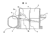
図5ないし図6は吸気通路の図2以外の他の実施例を示す。
【0014】
図11ないし図12には、従来品の空気流量特性に対する本発明の一実施形態における空気流量特性を示したものである。
【0015】
本スロットル装置が自動車用ディーゼルエンジンに搭載された場合の弁体位置を図2,図3に示す。
【0016】
自動車用ディーゼルエンジンの吸気絞り用吸気制御装置は図2,図3に示すように、スロットルボディ1に回転可能に支承された回転軸4に弁体3が取付けられている。
【0017】
また、スロットルボディ1にはモータ12が取付けられカバー13の内部にはギア機構(図示せず)と弁体3の開度を検知するセンサー(図示せず)が設けられている。
【0018】
ECU(エンジンコントロールユニット:図示せず)からの信号をカバー13に設けたコネクター14から取入れ、モータ12に伝達する。モータ12の動きで弁体3を制御する。
【0019】
弁体の開度はセンサで検知されコネクター14からECUに送られる。ECUはセンサからの信号と機関の要求する目標開度との偏差ができるだけ小さくなるよう信号を演算し出力する。
【0020】
弁体3は通常走行中は全開状態に位置している。弁体3が動作するのはエンジン停止時に燃焼室に供給する空気を遮断する場合、アイドル時にエンジン回転数を安定させるため空気流量を絞る場合、排気ガスを燃焼室上流側へ戻すための負圧を発生させる場合等がある。
【0021】
前記エンジンを停止させるようエンジン制御装置から指令が発信された時、吸入空気を遮断するためモータ12を介し回転軸4を作動させ弁体3を制御上の全閉位置3aに制御する。
【0022】
この時、弁体3は空気通路2の内壁に形成された空気通路溝5始まり位置のわずかに上流位置に位置するよう制御される。
【0023】
これにより図11に示すように従来のスロットル装置と同様に制御上の全閉位置における空気流量特性9を得ている。
【0024】
しかし、弁体3が制御上の全閉位置3aより下流側(例えば3b)にて固着した場合、従来の空気流量特性9ではエンジン始動および走行に可能な必要空気流量が確保できなかった。本実施例では、空気通路溝5を形成することで図11の図10に示すように弁体3の機械的全閉位置における空気流量を弁体3の制御上の全閉位置ににおける空気流量より増加させるよう構成した。
【0025】
これにより、弁体3が機械的全閉位置で動かなくなっても始動もしくは走行可能な吸入空気流量を確保できる。
【0026】
なお、図4に示す空気通路溝5の開口面積,形状,数及び位置を必要に応じて変化させることにより弁体3固着時以外の目的、例えば弁体3を閉じた時に発生する笛吹き音の低減や空気通路内2の急激な圧力変化を緩和することによる弁体3の保護、さらには弁体3の制御上の全閉位置付近での空気流量特性を任意に設定することができる。その結果図11に示すように、弁体3の制御上の全閉位置より下流側において徐々に空気流量を増加させる用に構成することができるという効果がある。
【0027】
この他にアイドル時の排気ガス成分コントロールや運転性向上のため、空気通路溝5の入口テーパ6領域を弁体3のアイドル位置における開口面積と合わせることで図12に示すような空気流量特性11を提供することができ、部品間のばらつきや弁体制御上のばらつきを吸収できるという効果がある。
【0028】
また、図5,図6のように空気通路2をストレートとせずに一部、球面とすることで、その球面範囲の弁開度において空気流量を一定または、それに近い特性とすることができる。
【0029】
また、一部球面にする場合、弁体3を開ける時、弁体3のエンジン側に堆積しているスラッジ(コンタミネーション)を弁体3がかき出し弁体3と空気通路の間でスティックするのを防ぐ利点がある。
【0030】
次にガソリンエンジン用スロットル装置(吸気制御装置)についての実施例を図7〜図10に基づいて説明する。
【0031】
本実施例のガソリンエンジン用スロットル装置における空気通路に形成された溝の一実施形態の平面図を図7に示す。図8は図7の断面図である。
【0032】
図9ないし図10は吸気通路の図8以外の他の実施例である。
【0033】
自動車用ガソリンエンジンに搭載される吸気制御装置は絞り弁をモータで駆動する。
【0034】
本発明を当該装置に適用した場合は以下の通り作動する。
【0035】
エンジン制御装置からのモータ駆動指令がない(モータへの電流供給がない)状態では絞り弁(弁体8)は戻しスプリングの作用でデフォルト開度(中間開度)、つまり機械的全閉位置8bに位置している。
【0036】
アイドル時には弁体3は制御上の全閉位置8aに位置するよう少し開き側に制御される。アクセルが一杯に踏み込まれた全負荷走行状態では弁体3の制御上の全開位置8cに制御される。
【0037】
本実施例の吸気制御装置では通常前記弁体8が制御上の全閉位置8aから制御上の全開位置8cの間にて開度制御され、図11の空気流量特性10の右上がり特性部を得る。これによって、通常走行時の吸入空気量が制御される。
【0038】
弁体8の位置を正確に把握するためエンジン始動時もしくはエンジン停止時に戻しスプリングによって機械的に弁体8を機械的全閉位置8bになるよう弁体を付勢し、このときの弁開度センサ出力値をエンジン制御装置にて学習する。
【0039】
従って、弁体8が弁体制御全閉位置8aから弁体機械的全閉位置8bの間にて固着した場合、従来の空気流量特性9ではエンジン始動および車輌走行に必要な空気流量を確保できなかった。
【0040】
本実施例では、空気通路溝5を形成することで図11の図10の左上がり部に示すように弁体8の機械的全閉位置8bにおける空気流量を弁体8の制御上の全閉位置8aに対し増加させた。
【0041】
これにより弁体8がこの領域で動かなくなっても(固着しても)機関の始動もしくは走行可能な吸入空気流量を充分確保できるという効果がある。
【0042】
また、この弁体8の制御上の全閉位置8aから下流側(例えば8b)に空気通路溝5を形成することで、モータ12への電流供給がない状態のとき、弁体8が機械的全閉位置8bに戻しバネの戻し力で戻されると、結果的に弁体8をデフォルト開度(中間開度)状態にできるため、デフォルト機構の機構部品を削減することができる(開き側に付勢するバネが不要になる)という効果がある。
【0043】
この場合、通気通路溝5の入口部テーパ6は必ずしも必要ではなく、弁体8の機械的全閉位置8bにおける必要開口面積が確保できていればよい。
【0044】
従ってこの実施例では溝5の形状を簡略できるという効果がある。
【0045】
また、ディーゼルエンジン用スロットル装置と同様に、必要に応じて空気通路溝5の開口面積,形状,数及び位置を、必要デフォルト空気流量に応じ変えても良い。なお、図9,図10は、図5,図6と同様に、空気通路2の一部を球面とすることで、その球面範囲の弁開度において空気流量の変化を一定ないしは、微小変化特性とすることもできる。
【0046】
本実施例の特徴を列挙すると以下のとおりである。
【0047】
ディーゼルエンジンの吸気絞り装置では絞り弁制御範囲の通路形状を筒状とし、空気通路内に設けた絞り弁の制御上の全閉位置近傍の下流に絞り弁をバイパスする空気通路溝(例えば、絞り弁外周全域に溝、又は部分的な溝)を形成することで前記領域における弁体と通路面との微少隙間部分を低減でき、吸気絞りの精密な制御が可能となる。
【0048】
また、空気通路溝の開口面積を調整することにより弁体が機械的全閉近辺にて固着しても車輌走行に必要な空気流量を供給できるようにしたものである。さらに、弁体の制御上の全閉位置から下流側の領域において、空気通路面積が一定となるようなテーパを形成することで弁体に位置ばらつきが生じても燃焼室内に一定空気流量を供給することができるようにしたものである。
【0049】
また、ガソリンエンジンの電制スロットル弁装置では、弁体制御範囲の通路に空気通路溝を形成することで、弁体を作動させる駆動装置としてのモータに電流が供給されなくなった時、戻しばねの戻し力で機械的全閉位置に弁が戻ってくると上記通路溝が車輌走行に必要な空気流量(従来のデフォルト開度位置で要求される空気量)を供給できるようにしたものである。
【0050】
実施例のスロットル装置によれば、ディーゼルエンジンにおいて部品点数を増加することなく弁体の固着を防止出来るとともに、制御領域より下流側にて固着しても車輌として走行可能な空気流量を確保することができ、また、弁体のアイドル位置における安定した空気流量を供給することができる。ガソリンエンジンにおいては、弁体駆動装置を持つスロットル装置での部品点数削減による従来機能を確保したものを供給することができる。
【0051】
【発明の効果】
本発明によれば吸気量の制御性を維持しながら簡単な構成で故障時の必要吸気量を得ることができる吸気制御装置を提供できた。
【図面の簡単な説明】
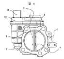
【図1】本発明のディーゼルエンジン用スロットル装置の一実施形態を示す平面図である。
【図2】図1の断面図である。
【図3】図2の実施形態を示す詳細図である。
【図4】図1の通気通路溝を下流側から見た図である。
【図5】図2の他の実施例である。
【図6】図2の他の実施例である。
【図7】本発明のガソリンエンジン用スロットル装置の一実施形態を示す平面図である。
【図8】図7の断面図である。
【図9】図8の他の実施例である。
【図10】図8の他の実施例である。
【図11】図2,図8の吸入空気流量を示す特性図である。
【図12】図2,図8の対応可能な吸入空気流量を示す特性図である。
【符号の説明】
1…スロットルボディ、2…空気通路、2a…球面空気通路、3,8…弁体、3a,8a…弁体制御全閉位置、3b,8b…弁体機械的全閉位置、4…回転軸、5…空気通路溝、6…溝入口テーパ部、7…取付フランジ、8c…弁体全開位置、9…従来品の空気流量特性、10…本発明品の空気流量特性、11…本発明の対応可能な空気流量特性、12…モータ、13…カバー、14…コネクター。[0001]
BACKGROUND OF THE INVENTION
The present invention relates to an intake control device that controls a throttle valve provided in the middle of an intake passage of an internal combustion engine (for example, a gasoline engine or a diesel engine) to adjust an opening area of the intake passage according to an operating state of the engine. This intake control device is used to control the intake air amount in the case of a gasoline engine, and is used as a throttle mechanism for the intake passage in the case of a diesel engine.
[0002]
[Prior art]
An intake control device for a diesel engine of an internal combustion engine is designed to be controlled to a position slightly opened from a mechanical fully closed position so that a sufficient clearance is maintained between the valve body and the intake passage wall surface even in a fully closed state. Even if the valve body stops moving in the fully closed state for control, engine stall does not occur.
[0003]
On the other hand, in a throttle device for a gasoline engine, in order to make a constant air flow leak when the motor current is cut off, for example, in
[0004]
[Patent Document 1]
Japanese Patent No. 02807033 [0005]
[Problems to be solved by the invention]
In the case of an intake device for a diesel engine, there is a large gap even when the valve body is in a fully closed state, and thus it was not possible to control the air flow rate to further reduce the air flow rate.
[0006]
Therefore, in one invention, the object is to make it possible to control the minimum intake amount when the intake throttle of the diesel engine is sufficiently small, and even if the throttle valve does not move at the intake throttle position (the failure of the drive motor or the restriction of the throttle valve). It is to provide an intake control device for a diesel engine that can secure a necessary air flow rate capable of starting and operating the engine.
[0010]
[Means for Solving the Problems]
In order to achieve the above object, the present invention includes a throttle body having an air passage, a throttle valve rotatably mounted in the air passage, and a motor for driving the throttle valve. In the intake control device for a diesel engine configured so that the throttle valve is located in a fully open state, the throttle valve has a mechanical fully closed position closer to the closed side than the control fully closed position, and the air passage is A groove for enlarging the area of the air passage is provided on the wall surface closer to the closed side than the fully closed position in the control of the throttle valve.
[0011]
DETAILED DESCRIPTION OF THE INVENTION
Embodiments of the present invention will be described below with reference to the drawings.
[0012]
FIGS. 1-6 shows one Embodiment of the groove | channel formed in the throttle apparatus air path of the diesel engine of this invention.
[0013]
5 to 6 show other embodiments of the intake passage other than FIG.
[0014]
11 to 12 show the air flow rate characteristics in one embodiment of the present invention with respect to the air flow rate characteristics of the conventional product.
[0015]
2 and 3 show the position of the valve body when the throttle device is mounted on an automobile diesel engine.
[0016]
As shown in FIGS. 2 and 3, an intake throttle intake control device for an automobile diesel engine has a
[0017]
A
[0018]
A signal from an ECU (engine control unit: not shown) is taken in from a
[0019]
The opening degree of the valve body is detected by a sensor and sent from the
[0020]
The
[0021]
When a command is sent from the engine control device to stop the engine, the
[0022]
At this time, the
[0023]
As a result, as shown in FIG. 11, the air
[0024]
However, when the
[0025]
As a result, it is possible to secure a flow rate of intake air that can be started or traveled even if the
[0026]
It should be noted that the whistling sound generated when the
[0027]
In addition to this, in order to control exhaust gas components during idling and improve operability, the
[0028]
Further, as shown in FIGS. 5 and 6, by partially forming a spherical surface of the
[0029]
In the case of a partially spherical surface, when the
[0030]
Next, an embodiment of a gasoline engine throttle device (intake control device) will be described with reference to FIGS.
[0031]
FIG. 7 shows a plan view of an embodiment of the groove formed in the air passage in the gasoline engine throttle device of this embodiment. FIG. 8 is a cross-sectional view of FIG.
[0032]
9 to 10 show other embodiments of the intake passage other than that shown in FIG.
[0033]
An intake control device mounted on an automobile gasoline engine drives a throttle valve with a motor.
[0034]
When the present invention is applied to the apparatus, it operates as follows.
[0035]
When there is no motor drive command from the engine control device (no current is supplied to the motor), the throttle valve (valve body 8) operates as a default opening (intermediate opening) by the action of the return spring, that is, the mechanical fully
[0036]
During idling, the
[0037]
In the intake control device of the present embodiment, the opening degree of the
[0038]
In order to accurately grasp the position of the
[0039]
Therefore, when the
[0040]
In the present embodiment, by forming the
[0041]
As a result, even if the
[0042]
Further, by forming the
[0043]
In this case, the
[0044]
Therefore, in this embodiment, there is an effect that the shape of the
[0045]
Similarly to the throttle device for a diesel engine, the opening area, shape, number, and position of the
[0046]
The characteristics of the present embodiment are listed as follows.
[0047]
In an intake throttle device of a diesel engine, the passage shape of the throttle valve control range is cylindrical, and an air passage groove that bypasses the throttle valve in the vicinity of the fully closed position in the control of the throttle valve provided in the air passage (for example, the throttle valve) By forming a groove or a partial groove on the entire outer periphery of the valve, a minute gap portion between the valve body and the passage surface in the region can be reduced, and precise control of the intake throttle can be performed.
[0048]
Further, by adjusting the opening area of the air passage groove, the air flow rate necessary for vehicle travel can be supplied even if the valve body is fixed in the vicinity of the mechanical full closure. Furthermore, by forming a taper that keeps the air passage area constant in the area downstream from the fully closed position in the control of the valve body, a constant air flow rate is supplied into the combustion chamber even if the position of the valve body varies. It is something that can be done.
[0049]
In addition, in an electric throttle valve device for a gasoline engine, an air passage groove is formed in the passage of the valve body control range, so that when no current is supplied to the motor as a drive device for operating the valve body, When the valve returns to the mechanical fully closed position by the return force, the passage groove can supply the air flow rate required for vehicle travel (the amount of air required at the conventional default opening position).
[0050]
According to the throttle device of the embodiment, it is possible to prevent sticking of the valve body without increasing the number of parts in the diesel engine, and to secure an air flow rate capable of traveling as a vehicle even if the valve body is stuck downstream from the control region. In addition, a stable air flow rate at the idle position of the valve body can be supplied. In a gasoline engine, a throttle device having a valve body drive device that has a conventional function by reducing the number of parts can be supplied.
[0051]
【The invention's effect】
According to the present invention, it is possible to provide an intake control device capable of obtaining a required intake amount at the time of failure with a simple configuration while maintaining controllability of the intake amount.
[Brief description of the drawings]
FIG. 1 is a plan view showing an embodiment of a throttle device for a diesel engine according to the present invention.
FIG. 2 is a cross-sectional view of FIG.
FIG. 3 is a detailed view showing the embodiment of FIG.
4 is a view of the ventilation passage groove of FIG. 1 as viewed from the downstream side.
FIG. 5 is another embodiment of FIG. 2;
FIG. 6 is another embodiment of FIG.
FIG. 7 is a plan view showing an embodiment of a throttle device for a gasoline engine according to the present invention.
8 is a cross-sectional view of FIG.
FIG. 9 is another embodiment of FIG.
10 is another embodiment of FIG.
11 is a characteristic diagram showing the intake air flow rate of FIGS. 2 and 8. FIG.
12 is a characteristic diagram showing the intake air flow rate that can be handled in FIGS. 2 and 8. FIG.
[Explanation of symbols]
DESCRIPTION OF
Claims (4)
前記空気通路内に回転可能に取り付けられた絞り弁と、
前記絞り弁を駆動するモータとを備え、
通常走行中は前記絞り弁が全開状態に位置するように構成されたディーゼルエンジンの吸気制御装置であって、
前記絞り弁は、制御上の全閉位置よりも閉じ側に機械的な全閉位置を備え、
前記空気通路は、前記絞り弁の制御上の全閉位置よりも閉じ側の壁面に、前記空気通路の面積を拡大する溝を備えたディーゼルエンジンの吸気制御装置。A throttle body with an air passage;
A throttle valve rotatably mounted in the air passage;
A motor for driving the throttle valve,
A diesel engine intake control device configured so that the throttle valve is positioned in a fully open state during normal travel,
The throttle valve has a mechanical fully closed position closer to the closed side than the fully closed position on control,
The air passage is an intake control device for a diesel engine provided with a groove that enlarges an area of the air passage on a wall surface closer to a closed side than a fully closed position in the control of the throttle valve.
Priority Applications (4)
| Application Number | Priority Date | Filing Date | Title |
|---|---|---|---|
| JP2002307783A JP3867654B2 (en) | 2002-10-23 | 2002-10-23 | Intake control device for internal combustion engine, intake control device for gasoline engine |
| US10/689,598 US7237759B2 (en) | 2002-10-23 | 2003-10-22 | Air intake control device for internal combustion engine and air intake control device for gasoline engine |
| EP03024000A EP1413722A3 (en) | 2002-10-23 | 2003-10-22 | Air intake control device for internal combustion engine and air intake control device for gasoline engine |
| CNB2003101025597A CN100416064C (en) | 2002-10-23 | 2003-10-23 | Suction control device of internal combustion engine, suction control device of gasoline engine |
Applications Claiming Priority (1)
| Application Number | Priority Date | Filing Date | Title |
|---|---|---|---|
| JP2002307783A JP3867654B2 (en) | 2002-10-23 | 2002-10-23 | Intake control device for internal combustion engine, intake control device for gasoline engine |
Publications (2)
| Publication Number | Publication Date |
|---|---|
| JP2004143976A JP2004143976A (en) | 2004-05-20 |
| JP3867654B2 true JP3867654B2 (en) | 2007-01-10 |
Family
ID=32064326
Family Applications (1)
| Application Number | Title | Priority Date | Filing Date |
|---|---|---|---|
| JP2002307783A Expired - Fee Related JP3867654B2 (en) | 2002-10-23 | 2002-10-23 | Intake control device for internal combustion engine, intake control device for gasoline engine |
Country Status (4)
| Country | Link |
|---|---|
| US (1) | US7237759B2 (en) |
| EP (1) | EP1413722A3 (en) |
| JP (1) | JP3867654B2 (en) |
| CN (1) | CN100416064C (en) |
Families Citing this family (11)
| Publication number | Priority date | Publication date | Assignee | Title |
|---|---|---|---|---|
| US7047936B2 (en) * | 2003-11-25 | 2006-05-23 | Aisan Kogyo Kabushiki Kaisha | Throttle bodies and methods of manufacturing such throttle bodies |
| JP2006017080A (en) * | 2004-07-05 | 2006-01-19 | Denso Corp | Intake air control device for internal combustion engine |
| JP4414322B2 (en) * | 2004-10-26 | 2010-02-10 | 株式会社ケーヒン | Intake control device for fuel injection device |
| DE102005031744A1 (en) * | 2005-07-07 | 2007-01-11 | GM Global Technology Operations, Inc., Detroit | Device for generating negative pressure in a motor vehicle |
| FR2901316A1 (en) * | 2006-05-19 | 2007-11-23 | Bosch Gmbh Robert | Method of detecting sticking charge movement flap of internal combustion engine, detects departures of inlet manifold airflow from modeled values |
| JP4630318B2 (en) * | 2007-08-29 | 2011-02-09 | 本田技研工業株式会社 | Throttle device for internal combustion engine |
| JP4885105B2 (en) * | 2007-10-11 | 2012-02-29 | 三菱重工業株式会社 | Fluid switching valve device, exhaust gas control valve and wastegate valve provided with the same |
| FR2962183B1 (en) * | 2010-06-30 | 2013-06-28 | Valeo Sys Controle Moteur Sas | FLUID CIRCULATION VALVE |
| FR2990743B1 (en) * | 2012-05-15 | 2014-05-02 | Valeo Sys Controle Moteur Sas | ENGINE CONTROL VALVE WITH IMPROVED SEALING |
| DE102016119426B4 (en) * | 2016-10-12 | 2020-03-12 | Pierburg Gmbh | Flap device for an internal combustion engine |
| CN113202635A (en) * | 2021-05-20 | 2021-08-03 | 重庆隆鑫机车有限公司 | Throttle valve body and engine |
Family Cites Families (31)
| Publication number | Priority date | Publication date | Assignee | Title |
|---|---|---|---|---|
| DE1080813B (en) | 1955-11-16 | 1960-04-28 | Richard Haller | Engine brake for vehicles with internal combustion engines |
| DE2427995A1 (en) | 1974-06-10 | 1976-01-02 | Standard Elektrik Lorenz Ag | Butterfly-type gas valve - has housing in two identical halves with widened cylindrical portions accommodating butterfly |
| JPS58202337A (en) | 1981-12-26 | 1983-11-25 | Aisin Seiki Co Ltd | Suction device for diesel engine |
| US4474150A (en) * | 1982-11-22 | 1984-10-02 | General Motors Corporation | Valve assembly |
| EP0116855B1 (en) * | 1983-01-21 | 1990-03-21 | Fujikin International, Inc. | Control valve |
| JPH03182643A (en) | 1989-12-12 | 1991-08-08 | Japan Electron Control Syst Co Ltd | Air intake device for internal combustion engine |
| JP2807033B2 (en) | 1990-03-22 | 1998-09-30 | 愛三工業株式会社 | Throttle valve control device |
| JPH06129935A (en) | 1992-10-20 | 1994-05-13 | Nippondenso Co Ltd | Intake gas throttle valve device of internal combustion engine |
| JP3203628B2 (en) | 1992-10-28 | 2001-08-27 | 株式会社デンソー | Intake throttle valve device for internal combustion engine |
| DE4306607A1 (en) | 1993-03-03 | 1994-09-08 | Bayerische Motoren Werke Ag | Throttle valve of an internal combustion engine |
| JP2982557B2 (en) | 1993-06-01 | 1999-11-22 | 三菱自動車工業株式会社 | Engine intake air control system |
| JPH07269375A (en) | 1994-03-30 | 1995-10-17 | Mikuni Corp | Intake air controller |
| JPH07269377A (en) | 1994-03-31 | 1995-10-17 | Mikuni Corp | Intake air controller |
| JP3787861B2 (en) * | 1995-07-14 | 2006-06-21 | 株式会社デンソー | Throttle valve device for internal combustion engine |
| JP3192355B2 (en) | 1995-09-20 | 2001-07-23 | 株式会社日立製作所 | Intake control device for internal combustion engine |
| JP3123908B2 (en) | 1995-10-30 | 2001-01-15 | 株式会社巴技術研究所 | Butterfly valve body |
| EP0869266A4 (en) | 1995-12-19 | 2000-06-21 | Hitachi Ltd | Throttle valve control device for an internal combustion engine |
| JPH09195803A (en) | 1996-01-16 | 1997-07-29 | Nissan Motor Co Ltd | Throttle valve device of internal combustion engine |
| JPH10103082A (en) | 1996-09-27 | 1998-04-21 | Aisan Ind Co Ltd | Intake throttle system for diesel engine |
| JPH10121992A (en) | 1996-10-18 | 1998-05-12 | Mitsubishi Electric Corp | Throttle valve control device for engine |
| IT1286795B1 (en) * | 1996-12-02 | 1998-07-17 | Magneti Marelli Spa | MOTORIZED THROTTLE BODY |
| JPH112170A (en) | 1997-06-11 | 1999-01-06 | Nippon Soken Inc | Idle intake control device |
| US6041754A (en) | 1997-04-14 | 2000-03-28 | Nippon Soken, Inc. | Idle intake control device |
| JPH11193726A (en) | 1997-12-26 | 1999-07-21 | Honda Motor Co Ltd | Seal structure of throttle device |
| DE19812089C1 (en) | 1998-03-19 | 1999-06-10 | Daimler Chrysler Ag | Intake for multiple cylinder internal combustion engine |
| JP2000018396A (en) | 1998-04-28 | 2000-01-18 | Bosch Braking Systems Co Ltd | Butterfly valve |
| JP2000110951A (en) | 1998-10-05 | 2000-04-18 | Jidosha Kiki Co Ltd | Butterfly valve |
| DE10044294A1 (en) * | 2000-09-07 | 2002-05-16 | Siemens Ag | throttle body |
| JP2002221036A (en) | 2001-01-26 | 2002-08-09 | Fuji Heavy Ind Ltd | Intake system for engine |
| JP2003343367A (en) | 2002-05-23 | 2003-12-03 | Hitachi Ltd | Fuel-heating type fuel injection system and internal combustion engine equipped therewith |
| KR100528193B1 (en) | 2002-06-29 | 2005-11-15 | 현대자동차주식회사 | Reduction device of ISCA driving noise |
-
2002
- 2002-10-23 JP JP2002307783A patent/JP3867654B2/en not_active Expired - Fee Related
-
2003
- 2003-10-22 US US10/689,598 patent/US7237759B2/en not_active Expired - Lifetime
- 2003-10-22 EP EP03024000A patent/EP1413722A3/en not_active Withdrawn
- 2003-10-23 CN CNB2003101025597A patent/CN100416064C/en not_active Expired - Fee Related
Also Published As
| Publication number | Publication date |
|---|---|
| EP1413722A2 (en) | 2004-04-28 |
| JP2004143976A (en) | 2004-05-20 |
| CN100416064C (en) | 2008-09-03 |
| US20040079327A1 (en) | 2004-04-29 |
| EP1413722A3 (en) | 2006-12-13 |
| US7237759B2 (en) | 2007-07-03 |
| CN1497149A (en) | 2004-05-19 |
Similar Documents
| Publication | Publication Date | Title |
|---|---|---|
| JP3867654B2 (en) | Intake control device for internal combustion engine, intake control device for gasoline engine | |
| JP2004003421A (en) | Device for opening and closing throttle valve | |
| JPH0988640A (en) | Intake control device for internal combustion engine | |
| JP3887309B2 (en) | Bypass intake air amount control device | |
| US6488009B2 (en) | Throttles | |
| JP3966807B2 (en) | Engine idle intake control system | |
| JP2002349396A (en) | Bypass intake air amount control device | |
| JPH11257103A (en) | Throttle opening diagnostic device | |
| JPS5918124Y2 (en) | Internal combustion engine speed control device | |
| JPH10103082A (en) | Intake throttle system for diesel engine | |
| JPS6224035Y2 (en) | ||
| JP3286231B2 (en) | Throttle valve device | |
| JPH0159416B2 (en) | ||
| JPH0236912Y2 (en) | ||
| JPH0586906A (en) | Rotational speed controller for internal combustion engine | |
| JPH0688540A (en) | Throttle valve on-off device | |
| KR19980051829A (en) | Throttle valve open / close control device of vehicle engine | |
| JP2984705B2 (en) | Engine intake control valve device | |
| JPH0381534A (en) | Motor driven throttle device | |
| JPS5913333Y2 (en) | Air cleaner for internal combustion engines | |
| KR19980072674A (en) | Throttle valve device for preventing starting and stopping of cars | |
| KR100250205B1 (en) | Double throttle valve for vehicle engine | |
| JP2000120451A (en) | Intake air control device for internal combustion engine | |
| JPH05141281A (en) | Throttle valve control device | |
| JPH02157475A (en) | Device for controlling flow rate of intake air of engine |
Legal Events
| Date | Code | Title | Description |
|---|---|---|---|
| RD01 | Notification of change of attorney |
Free format text: JAPANESE INTERMEDIATE CODE: A7421 Effective date: 20060420 |
|
| A977 | Report on retrieval |
Free format text: JAPANESE INTERMEDIATE CODE: A971007 Effective date: 20060425 |
|
| A131 | Notification of reasons for refusal |
Free format text: JAPANESE INTERMEDIATE CODE: A131 Effective date: 20060509 |
|
| A521 | Request for written amendment filed |
Free format text: JAPANESE INTERMEDIATE CODE: A523 Effective date: 20060710 |
|
| TRDD | Decision of grant or rejection written | ||
| A01 | Written decision to grant a patent or to grant a registration (utility model) |
Free format text: JAPANESE INTERMEDIATE CODE: A01 Effective date: 20060919 |
|
| A61 | First payment of annual fees (during grant procedure) |
Free format text: JAPANESE INTERMEDIATE CODE: A61 Effective date: 20061002 |
|
| R151 | Written notification of patent or utility model registration |
Ref document number: 3867654 Country of ref document: JP Free format text: JAPANESE INTERMEDIATE CODE: R151 |
|
| FPAY | Renewal fee payment (event date is renewal date of database) |
Free format text: PAYMENT UNTIL: 20091020 Year of fee payment: 3 |
|
| FPAY | Renewal fee payment (event date is renewal date of database) |
Free format text: PAYMENT UNTIL: 20101020 Year of fee payment: 4 |
|
| FPAY | Renewal fee payment (event date is renewal date of database) |
Free format text: PAYMENT UNTIL: 20101020 Year of fee payment: 4 |
|
| S111 | Request for change of ownership or part of ownership |
Free format text: JAPANESE INTERMEDIATE CODE: R313111 |
|
| FPAY | Renewal fee payment (event date is renewal date of database) |
Free format text: PAYMENT UNTIL: 20101020 Year of fee payment: 4 |
|
| R350 | Written notification of registration of transfer |
Free format text: JAPANESE INTERMEDIATE CODE: R350 |
|
| FPAY | Renewal fee payment (event date is renewal date of database) |
Free format text: PAYMENT UNTIL: 20111020 Year of fee payment: 5 |
|
| FPAY | Renewal fee payment (event date is renewal date of database) |
Free format text: PAYMENT UNTIL: 20121020 Year of fee payment: 6 |
|
| FPAY | Renewal fee payment (event date is renewal date of database) |
Free format text: PAYMENT UNTIL: 20121020 Year of fee payment: 6 |
|
| FPAY | Renewal fee payment (event date is renewal date of database) |
Free format text: PAYMENT UNTIL: 20131020 Year of fee payment: 7 |
|
| LAPS | Cancellation because of no payment of annual fees |