JP3861082B2 - Steel curb and drainage unit - Google Patents
Steel curb and drainage unit Download PDFInfo
- Publication number
- JP3861082B2 JP3861082B2 JP2003296955A JP2003296955A JP3861082B2 JP 3861082 B2 JP3861082 B2 JP 3861082B2 JP 2003296955 A JP2003296955 A JP 2003296955A JP 2003296955 A JP2003296955 A JP 2003296955A JP 3861082 B2 JP3861082 B2 JP 3861082B2
- Authority
- JP
- Japan
- Prior art keywords
- lid
- plate
- guard post
- water
- curb
- Prior art date
- Legal status (The legal status is an assumption and is not a legal conclusion. Google has not performed a legal analysis and makes no representation as to the accuracy of the status listed.)
- Expired - Fee Related
Links
Images


Landscapes
- Road Paving Structures (AREA)
- Sewage (AREA)
Description
本発明は、道路の路肩や中央分離帯等に設置して自動車が道路から外れないようにガードするとともに道路の排水も行うことのできる鋼製の縁石兼排水溝ユニットに関する。 The present invention relates to a steel curb and drainage groove unit that can be installed on a shoulder of a road, a median strip, or the like to guard an automobile from coming off the road and drain the road.
自動車が道路から外れないようにしたり、路面の雨水等を排水する方法として、路肩や中央分離帯に設置するとともに側溝を形成し、縁石により自動車が道路から外れることを防止し、路面の雨水等を側溝に流す方法や、路肩や中央分離帯に上方をタイヤ支承部とする縁石と内方を排水溝とする水路部とにより形成し、全体として鋼製中空体としてなる縁石兼排水溝ユニットを設置し、縁石部により自動車が道路から外れないようにし、雨水等を水路部に導く方法とがよく知られている。 As a method of preventing the car from coming off the road or draining rainwater etc. on the road surface, it is installed on the road shoulder and the median strip and a gutter is formed to prevent the car from coming off the road by the curb, rainwater on the road surface, etc. A curb and drainage groove unit formed as a steel hollow body as a whole with a curbstone with a tire support part on the shoulder and a center separation band and a waterway part with a drainage groove on the inside. It is well known to install it, prevent the car from coming off the road by the curb, and guide rainwater to the waterway.
前者の方法は古くから行われているが、後掲する実用新案及び特許等において、本発明者が提案して以来行われているものである。 The former method has been practiced since ancient times, but has been practiced since the inventor proposed in utility models and patents to be described later.
後者の方法によれば、鋼製縁石兼排水溝ユニットを用いて容易にガード列を作ることができ、上方を縁石とするとともに水路部により内部を雨水等の排水路として利用することができ、コンクリート縁石のように縁石の設置と排水溝の設置作業を別個に分けて行う必要はない。そのため普及にはめざましいものがある。また、道路橋にあっては、鋼製縁石兼排水溝ユニットが中空体であるため死荷重の軽減も図れる。 According to the latter method, it is possible to easily make a guard row using a steel curb and drainage groove unit, and use the curbstone on the upper side and use the interior as a drainage channel for rainwater, etc. There is no need to separate the curb installation and drainage installation work separately from the concrete curb. Therefore, there is a remarkable spread. Moreover, in a road bridge, since the steel curb and drainage unit is a hollow body, the dead load can be reduced.
これらの提案において、鋼製縁石兼排水溝ユニットは、通常、縁石部としての蓋部と流水部とは蓋部の開閉のため分離可能に製作され、例えば図10に示すように蓋部2と流水部3とからなり、蓋部2は、タイヤ支承面2aと集水面2bと上面板2cとから形成されてなり、流水部3は、前面板3a、底面板3b、後面板3cとから形成されてなる。タイヤ支承面2aが斜面に形成されている場合は、上面板2cをそのまま兼ねているものもある。7は蓋部2のタイヤ支承面2aの裏面と上面板2cの裏面に取り付けられている蓋部2の補強リブである。
In these proposals, the steel curb-cum-drainage unit is normally manufactured so that the lid part and the flowing water part as the curb part are separable for opening and closing the lid part. For example, as shown in FIG. The
この例では、蓋部2と流水部3とは、流水部3の後面板3cの内面に取り付けられた受け部5に蓋部2の上面板2cの端部を、流水部3の前面板3aの内面に取り付けられた受け部6に蓋部2の集水面2bを載置してある。8、9はそれぞれピン挿入環で、ここにピンを挿入して蓋部2が流水部3から外れないようにする。
In this example, the
このようにしてなる鋼製縁石兼排水溝ユニットは、道路橋の路肩や一般道路の車道と歩道との境界に複数設置されてガード列を形成する。設置された鋼製縁石兼排水溝は、その集水面が路面を兼ねるので道路幅員を有効に使用できる。
車道と歩道とからなる道路にあっては、鋼製縁石兼排水溝ユニットを車道側に、ガードポストを歩道側に設置する。ガードポストを歩道側に設置すると歩道の有効幅員を減少させるという課題を有する。 On roads consisting of a roadway and a sidewalk, a steel curb and drainage unit is installed on the side of the road, and guard posts are installed on the sidewalk. If the guard post is installed on the sidewalk side, there is a problem of reducing the effective width of the sidewalk.
そこで、ガードポストの設置を歩道や車道の路面ではなく、この鋼製縁石兼排水溝ユニット上に設置することができれば、道路幅員の有効幅を減少させなくても済み、非常に有効的である。 Therefore, if the guard post can be installed not on the sidewalk or road surface but on this steel curb / drainage unit, it is not necessary to reduce the effective width of the road width, which is very effective. .
しかしながら、この鋼製縁石兼排水溝ユニットの上にガードポストを設置すると縁石部である蓋部の開閉ができなくなり、また、蓋部に自動車が衝突して破損したとき、蓋部の交換を不可能にしてしまう。 However, if a guard post is installed on the steel curb / drainage unit, the lid, which is the curb, cannot be opened and closed, and if the vehicle collides with the lid and is damaged, the lid cannot be replaced. Make it possible.
本発明は、上記課題を以下述べるところにより解決しようとするものである。 The present invention intends to solve the above problems as described below.
まず、本発明に係るタイヤ支承面と集水面と上面板を有する縁石部としての蓋部と排水溝としての流水部を有する鋼製縁石兼排水溝ユニットにおいて、集水面とタイヤ支承面と上面板とからなる蓋部と、後面板の両端方をガードポスト固定部の接続しろとし、このガード固定部の接続しろ相当を蓋部の寸法よりも長くした寸法の前面板・底面板・後面板とからなり、前面板上方と後面板上方に蓋部の受け部を取り付けてなる流水部と、流水部の後面板の接続しろ内面及び隣り合う別のユニットの後面板の接続しろ内面に密接する後面板と蓋部のタイヤ支承面・集水面・上面板とほぼ面一となる面を有する形状のガードポスト固定部とからなり、蓋部を流水部に取り付けた受け部に載置するとともにガードポスト固定部を流水部の互いの接続しろを利用して結合することを特徴とする鋼製縁石兼排水溝ユニットを提供する。 First, in the steel curb and drainage groove unit having a lid portion as a curb portion having a tire bearing surface, a water collecting surface and an upper surface plate and a water flowing portion as a drainage groove according to the present invention, the water collection surface, the tire bearing surface and the upper surface plate. A front plate, a bottom plate, and a rear plate having dimensions that are longer than the dimensions of the lid, with the cover portion and the both ends of the rear plate being connected to the guard post fixing portion. After connecting the inner surface of the flowing water portion with the receiving portion of the lid portion above the front plate and the upper surface of the front plate and the inner surface of the rear surface plate of the flowing water portion and the inner surface of the connecting surface of the rear plate of another adjacent unit It consists of a face plate and a guard post fixing part having a shape that is almost flush with the tire bearing surface, water collecting surface, and top surface plate of the cover part, and the cover part is placed on a receiving part attached to the flowing water part and the guard post Connect the fixed parts to each other Providing a steel curb and draining groove unit, characterized in that bind utilized.
そして、ガードポストとの関係においては、ガードポスト固定部にガードポストを固定することを特徴とする鋼製縁石兼排水溝ユニットを提供する。 And in relation with a guard post, the steel curb and drainage groove unit characterized by fixing a guard post to a guard post fixed part is provided.
本発明に係る鋼製縁石兼排水溝ユニットは、両端部の長さを蓋部の長さよりガードポスト固定部の接続しろ相当について長くした流水部に、この流水部の接続しろ及び同様に形成した隣り合う別のユニットの接続しろとを後面に有し、他を蓋部とほぼ面一とする形状のガードポスト固定部を接続しろを利用して結合して形成されるので、同様に形成されたユニット同士を隣り合わせて、一方の流水部に結合されているガードポスト固定部の隣り合う別のユニット用接続しろと隣り合う別のユニットの流水部の接続しろとを結合して、ユニットを水密に連続させることができる。 The steel curb and drainage groove unit according to the present invention is formed in the same manner as the margin of the flowing water and the same in the flowing portion where the length of both ends is longer than the length of the lid for the connecting length of the guard post fixing portion. It is formed in the same way because it is formed by connecting a guard post fixing part having a shape that has a connection margin of another adjacent unit on the rear surface and the other part being substantially flush with the lid part. Units adjacent to each other, and a guard post fixing part that is connected to one of the water flow parts is connected to a connection part for another adjacent unit and a connection part of the water supply part of another adjacent unit to make the unit watertight. Can be continuous.
ユニットを連続させた後は、ガードポスト固定部にガードポストを設置することができるので、路面上にガードポストを設置しなくても済むから、道路幅員を有効に利用することができる。 After the units are made continuous, the guard post can be installed on the guard post fixing portion, so that it is not necessary to install the guard post on the road surface, so that the road width can be used effectively.
蓋部の開閉に支障はないので、蓋部が破損したときの蓋部の交換、流水部の清掃もこれまでどおり行うことができる。 Since there is no hindrance to the opening and closing of the lid portion, the replacement of the lid portion when the lid portion is damaged and the cleaning of the flowing water portion can be performed as before.
本発明を実施するための最良の形態を以下図面に基き説明する。 The best mode for carrying out the present invention will be described below with reference to the drawings.
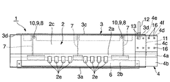
図1は、本発明の一実施の形態を示す平面図、図2は同正面図、図3は図2のA−A断面図、図4は同B−B断面図、図5は同C−C断面図である。 1 is a plan view showing an embodiment of the present invention, FIG. 2 is a front view thereof, FIG. 3 is a sectional view taken along line AA in FIG. 2, FIG. 4 is a sectional view taken along line BB, and FIG. It is -C sectional drawing.
鋼製縁石兼排水溝ユニット1は、蓋部2、流水部3、ガードポスト固定部4とからなっている。
The steel curb and
蓋部2は、タイヤ支承面2aを路面にほぼ面一な平面の集水面2bから立ち上げ、集水面2bと反対方向に延伸する上面板2cとからなる。図において、2eは路面からの水を集水する集水孔、7は補強リブ、8、9は補強リブ7、後述の流水部3の後面板3cに取り付けられ直列になっているピン挿入環、10はピン挿入口である。
The
流水部3は、流水路を形成する前面板3a、底面板3b、後面板3cとからなり、前面板3aの上方内面に蓋部2の集水面2bの端部を載置する受け部6、後面板3cの上方内面に蓋部2の上面板2cの端部を載置する受け部5がL型鋼により取り付けられている。なお、受け部5は、後述するガードポスト固定部4を結合する接続しろ部分については不要である。流水部3は、後述するガードポスト固定部4を結合するため、上述の蓋部2の長さよりも両端方に接続しろ3d分だけ前面板3a、底面板3b、後面板3cともに長い寸法となっている。
The flowing
ガードポスト固定部4は、蓋部2のタイヤ支承面2a、集水面2b、上面板2cとほぼ面一となるタイヤ支承面4a、集水面4b、上面板4cと流水部3の後面板3cの上述した接続しろ3dに結合するとともに同様に形成された隣り合うユニットの接続しろと結合する接続しろ4e、4fとなる後面板4dとからなる。11は補強リブである。図において、ガードポスト固定部4は、タイヤ支承面4aと集水面4bとからなる部材と上面板4cと後面板4dとからなる部材は別部材によりなるが一体のものであってよいこともちろんである。
The guard
上記において、各部の取り付けは原則として溶接による。 In the above, each part is attached by welding in principle.
このようにしてなる各部は、つぎのようにして一体となる。 Each part formed in this way is integrated as follows.
流水部3とガードポスト固定部4とは、流水部3とガードポスト固定部4とをそれぞれの後面板3c、4dの接続しろ3d、4eを合わせて、アンカーボルト12とナット13で締結して一体となる。
The flowing
蓋部2と流水部3とは、流水部3の後面板3cの内面に取り付けられた受け部5に蓋部2の上面板2cの端部を載置するとともに流水部3の前面板3aの内面に取り付けられた受け部6に蓋部2の集水面2bの端部を載置する。蓋部2と流水部3とがはずれないようにするためにピン挿入口10からそれぞれに取り付けた挿入環8、9にピンを挿通する。
The
このようにして、蓋部2と流水部3とガードポスト固定部4は水密に結合される。
In this way, the
図6は上述の鋼製縁石兼排水溝ユニットを複数連続して並べてガードポスト固定部にガードポストを固定した正面図を示し、図7は、同蓋部開口状態の正面図を示す。 FIG. 6 shows a front view in which a plurality of the above-mentioned steel curb and drainage groove units are continuously arranged and the guard post is fixed to the guard post fixing portion, and FIG. 7 is a front view of the lid portion opening state.
図6、図7において、同形状に形成された隣り合う鋼製縁石兼排水溝ユニット1同士は、一方の流水部3の後面板3cの接続しろ3dに取り付けられているガードポスト固定部4の後面板4dの接続しろ4fと他方の流水部3の後面板3cの接続しろ3dとを合わせ、図示してないが、ボルト、ナットによる締結のために開孔されているボルト穴を利用してアンカーボルト12、ナット13により締結して結合される。ガードポスト14は、蓋部2をまたぐようにしてガードポスト固定部4に固定される。固定方法は問わない。ガードポストはガードポスト固定部4の上に蓋部2を避けて設置されるので、蓋部2の開口は自在である。
6 and 7, the adjacent steel curb stone and
なお、蓋部2、流水部3、ガードポスト固定部4、ガードポスト14はいずれも別々に製作し、現場において組み立ててよい。
In addition, the
図8、図9は、本発明に係る鋼製縁石兼排水溝ユニットを車道と歩道の境界に設置した状態を示す側面図及び同蓋部開口状態を示す側面図である。 8 and 9 are a side view showing a state where the steel curb and drainage unit according to the present invention is installed at the boundary between the roadway and the sidewalk, and a side view showing the lid opening state.
この図において、鋼製縁石兼排水溝ユニット1を車道側に蓋部2の集水面が面一になるようにして歩道側に流水部3の後面板3c側からのアンカーボルト12を埋設して固定する。ガードポスト14は必要に応じてボルト16、ナット17により取り付けた補強板15を間にしてガードポスト固定部4に設置する。ガードポスト14は蓋部2をまたいでいるのでガードポスト14を設置しても蓋部2の開口の妨げとはならない。
In this figure, an
本発明は、上述のようにしてなるが、この例に限定されるものでないことはもちろんである。 The present invention is configured as described above, but it is needless to say that the present invention is not limited to this example.
本発明は、道路橋、一般道路に設置して、自動車が道路からはずれないようにしたり、路面の排水をするために広く利用される。 The present invention is widely used for installation on road bridges and general roads so that automobiles do not come off the road or drain the road surface.
1 鋼製縁石兼排水溝ユニット
2 蓋部
2a タイヤ支承部
2b 集水面
2c 上面板
2e 集水孔
3 流水部
3a 前面板
3b 底面板
3c 後面板
3d 接続しろ
4 ガードポスト固定部
4a タイヤ支承面
4b 集水面
4c 上面板
4d 後面板
4e 接続しろ
4f 接続しろ
5 受け部
6 受け部
7 補強リブ
8 ピン挿入環
9 ピン挿入環
10 ピン挿入口
11 補強リブ
12 アンカーボルト
13 ナット
14 ガードポスト
15 補強板
16 ボルト
17 ナット
DESCRIPTION OF
Claims (2)
Priority Applications (1)
| Application Number | Priority Date | Filing Date | Title |
|---|---|---|---|
| JP2003296955A JP3861082B2 (en) | 2003-08-21 | 2003-08-21 | Steel curb and drainage unit |
Applications Claiming Priority (1)
| Application Number | Priority Date | Filing Date | Title |
|---|---|---|---|
| JP2003296955A JP3861082B2 (en) | 2003-08-21 | 2003-08-21 | Steel curb and drainage unit |
Publications (2)
| Publication Number | Publication Date |
|---|---|
| JP2005068693A JP2005068693A (en) | 2005-03-17 |
| JP3861082B2 true JP3861082B2 (en) | 2006-12-20 |
Family
ID=34402951
Family Applications (1)
| Application Number | Title | Priority Date | Filing Date |
|---|---|---|---|
| JP2003296955A Expired - Fee Related JP3861082B2 (en) | 2003-08-21 | 2003-08-21 | Steel curb and drainage unit |
Country Status (1)
| Country | Link |
|---|---|
| JP (1) | JP3861082B2 (en) |
Families Citing this family (3)
| Publication number | Priority date | Publication date | Assignee | Title |
|---|---|---|---|---|
| JP4897551B2 (en) * | 2007-04-13 | 2012-03-14 | 繁之 松井 | Pedestrian boundary drainage device |
| JP5071731B2 (en) * | 2008-04-04 | 2012-11-14 | アース建設コンサルタント株式会社 | Surface improvement method for structure, surface improvement material for structure and manufacturing method thereof |
| JP5973796B2 (en) * | 2012-06-12 | 2016-08-23 | 株式会社ダイクレ | Floor slab widening unit |
-
2003
- 2003-08-21 JP JP2003296955A patent/JP3861082B2/en not_active Expired - Fee Related
Also Published As
| Publication number | Publication date |
|---|---|
| JP2005068693A (en) | 2005-03-17 |
Similar Documents
| Publication | Publication Date | Title |
|---|---|---|
| JP3861082B2 (en) | Steel curb and drainage unit | |
| JP3753715B2 (en) | Steel curb and drainage unit | |
| KR100466889B1 (en) | A sidewalk block for road | |
| JP2005023540A (en) | Drain gutter unit used for steel-made curb | |
| JP3712403B2 (en) | Steel curb and drainage unit | |
| JPH0218151Y2 (en) | ||
| JP4528743B2 (en) | Side gutter drainage and side gutter construction method | |
| JP3127873U (en) | Side groove and lid structure | |
| KR200351164Y1 (en) | Safety fence of road | |
| KR200387163Y1 (en) | Trench cover | |
| KR200219085Y1 (en) | Drainage for boundary stone use median strip | |
| JP3000258B2 (en) | Pedestrian road boundary construction method using boundary side groove blocks | |
| KR200340204Y1 (en) | Drainage pipe with a mesh plate fixed to a drain outlet | |
| JPH086367B2 (en) | Drainage block | |
| KR200154814Y1 (en) | A median strip for f.r.p | |
| JP3228283U (en) | Drainage ditch unit | |
| KR200366531Y1 (en) | A sidewalk block for road | |
| JP3047285U (en) | Precast concrete culvert and drainage structure using it | |
| JP2005264561A (en) | Sidewalk-driveway boundary block and drainage structure of permeable pavement | |
| JP3049872U (en) | Easy-to-plant sidewalk block | |
| JPH0647926Y2 (en) | Steel drainage groove and auto guard unit | |
| JP2001348808A (en) | Drainage ditch unit also serving as steel curbstone | |
| JP2006233429A (en) | Drainage block | |
| KR100811820B1 (en) | Trench cover with a waste rubber | |
| KR900008178Y1 (en) | Drainage device in the street |
Legal Events
| Date | Code | Title | Description |
|---|---|---|---|
| A977 | Report on retrieval |
Free format text: JAPANESE INTERMEDIATE CODE: A971007 Effective date: 20051213 |
|
| A131 | Notification of reasons for refusal |
Free format text: JAPANESE INTERMEDIATE CODE: A131 Effective date: 20060221 |
|
| A521 | Written amendment |
Free format text: JAPANESE INTERMEDIATE CODE: A523 Effective date: 20060419 |
|
| TRDD | Decision of grant or rejection written | ||
| A01 | Written decision to grant a patent or to grant a registration (utility model) |
Free format text: JAPANESE INTERMEDIATE CODE: A01 Effective date: 20060830 |
|
| A61 | First payment of annual fees (during grant procedure) |
Free format text: JAPANESE INTERMEDIATE CODE: A61 Effective date: 20060925 |
|
| R150 | Certificate of patent or registration of utility model |
Free format text: JAPANESE INTERMEDIATE CODE: R150 |
|
| FPAY | Renewal fee payment (event date is renewal date of database) |
Free format text: PAYMENT UNTIL: 20090929 Year of fee payment: 3 |
|
| S111 | Request for change of ownership or part of ownership |
Free format text: JAPANESE INTERMEDIATE CODE: R313113 |
|
| FPAY | Renewal fee payment (event date is renewal date of database) |
Free format text: PAYMENT UNTIL: 20090929 Year of fee payment: 3 |
|
| R350 | Written notification of registration of transfer |
Free format text: JAPANESE INTERMEDIATE CODE: R350 |
|
| FPAY | Renewal fee payment (event date is renewal date of database) |
Free format text: PAYMENT UNTIL: 20100929 Year of fee payment: 4 |
|
| FPAY | Renewal fee payment (event date is renewal date of database) |
Free format text: PAYMENT UNTIL: 20120929 Year of fee payment: 6 |
|
| FPAY | Renewal fee payment (event date is renewal date of database) |
Free format text: PAYMENT UNTIL: 20130929 Year of fee payment: 7 |
|
| R250 | Receipt of annual fees |
Free format text: JAPANESE INTERMEDIATE CODE: R250 |
|
| R250 | Receipt of annual fees |
Free format text: JAPANESE INTERMEDIATE CODE: R250 |
|
| R250 | Receipt of annual fees |
Free format text: JAPANESE INTERMEDIATE CODE: R250 |
|
| LAPS | Cancellation because of no payment of annual fees |