JP3861007B2 - Banknote deposit and withdrawal device and automatic cash transaction device - Google Patents
Banknote deposit and withdrawal device and automatic cash transaction device Download PDFInfo
- Publication number
- JP3861007B2 JP3861007B2 JP2002000229A JP2002000229A JP3861007B2 JP 3861007 B2 JP3861007 B2 JP 3861007B2 JP 2002000229 A JP2002000229 A JP 2002000229A JP 2002000229 A JP2002000229 A JP 2002000229A JP 3861007 B2 JP3861007 B2 JP 3861007B2
- Authority
- JP
- Japan
- Prior art keywords
- banknote
- banknotes
- bill
- unit
- space
- Prior art date
- Legal status (The legal status is an assumption and is not a legal conclusion. Google has not performed a legal analysis and makes no representation as to the accuracy of the status listed.)
- Expired - Fee Related
Links
Images


Classifications
-
- G—PHYSICS
- G07—CHECKING-DEVICES
- G07D—HANDLING OF COINS OR VALUABLE PAPERS, e.g. TESTING, SORTING BY DENOMINATIONS, COUNTING, DISPENSING, CHANGING OR DEPOSITING
- G07D9/00—Counting coins; Handling of coins not provided for in the other groups of this subclass
-
- G—PHYSICS
- G07—CHECKING-DEVICES
- G07D—HANDLING OF COINS OR VALUABLE PAPERS, e.g. TESTING, SORTING BY DENOMINATIONS, COUNTING, DISPENSING, CHANGING OR DEPOSITING
- G07D11/00—Devices accepting coins; Devices accepting, dispensing, sorting or counting valuable papers
- G07D11/10—Mechanical details
- G07D11/12—Containers for valuable papers
- G07D11/13—Containers for valuable papers with internal means for handling valuable papers
-
- B—PERFORMING OPERATIONS; TRANSPORTING
- B65—CONVEYING; PACKING; STORING; HANDLING THIN OR FILAMENTARY MATERIAL
- B65H—HANDLING THIN OR FILAMENTARY MATERIAL, e.g. SHEETS, WEBS, CABLES
- B65H29/00—Delivering or advancing articles from machines; Advancing articles to or into piles
- B65H29/38—Delivering or advancing articles from machines; Advancing articles to or into piles by movable piling or advancing arms, frames, plates, or like members with which the articles are maintained in face contact
- B65H29/40—Members rotated about an axis perpendicular to direction of article movement, e.g. star-wheels formed by S-shaped members
-
- B—PERFORMING OPERATIONS; TRANSPORTING
- B65—CONVEYING; PACKING; STORING; HANDLING THIN OR FILAMENTARY MATERIAL
- B65H—HANDLING THIN OR FILAMENTARY MATERIAL, e.g. SHEETS, WEBS, CABLES
- B65H31/00—Pile receivers
- B65H31/04—Pile receivers with movable end support arranged to recede as pile accumulates
- B65H31/06—Pile receivers with movable end support arranged to recede as pile accumulates the articles being piled on edge
-
- B—PERFORMING OPERATIONS; TRANSPORTING
- B65—CONVEYING; PACKING; STORING; HANDLING THIN OR FILAMENTARY MATERIAL
- B65H—HANDLING THIN OR FILAMENTARY MATERIAL, e.g. SHEETS, WEBS, CABLES
- B65H83/00—Combinations of piling and depiling operations, e.g. performed simultaneously, of interest apart from the single operation of piling or depiling as such
- B65H83/02—Combinations of piling and depiling operations, e.g. performed simultaneously, of interest apart from the single operation of piling or depiling as such performed on the same pile or stack
- B65H83/025—Combinations of piling and depiling operations, e.g. performed simultaneously, of interest apart from the single operation of piling or depiling as such performed on the same pile or stack onto and from the same side of the pile or stack
-
- G—PHYSICS
- G07—CHECKING-DEVICES
- G07D—HANDLING OF COINS OR VALUABLE PAPERS, e.g. TESTING, SORTING BY DENOMINATIONS, COUNTING, DISPENSING, CHANGING OR DEPOSITING
- G07D11/00—Devices accepting coins; Devices accepting, dispensing, sorting or counting valuable papers
- G07D11/20—Controlling or monitoring the operation of devices; Data handling
- G07D11/24—Managing the inventory of valuable papers
- G07D11/245—Replenishment
-
- G—PHYSICS
- G07—CHECKING-DEVICES
- G07D—HANDLING OF COINS OR VALUABLE PAPERS, e.g. TESTING, SORTING BY DENOMINATIONS, COUNTING, DISPENSING, CHANGING OR DEPOSITING
- G07D11/00—Devices accepting coins; Devices accepting, dispensing, sorting or counting valuable papers
- G07D11/20—Controlling or monitoring the operation of devices; Data handling
- G07D11/24—Managing the inventory of valuable papers
- G07D11/25—Relocation of valuable papers within devices
-
- B—PERFORMING OPERATIONS; TRANSPORTING
- B65—CONVEYING; PACKING; STORING; HANDLING THIN OR FILAMENTARY MATERIAL
- B65H—HANDLING THIN OR FILAMENTARY MATERIAL, e.g. SHEETS, WEBS, CABLES
- B65H2301/00—Handling processes for sheets or webs
- B65H2301/40—Type of handling process
- B65H2301/42—Piling, depiling, handling piles
- B65H2301/421—Forming a pile
- B65H2301/4214—Forming a pile of articles on edge
- B65H2301/42142—Forming a pile of articles on edge by introducing articles from beneath
-
- B—PERFORMING OPERATIONS; TRANSPORTING
- B65—CONVEYING; PACKING; STORING; HANDLING THIN OR FILAMENTARY MATERIAL
- B65H—HANDLING THIN OR FILAMENTARY MATERIAL, e.g. SHEETS, WEBS, CABLES
- B65H2301/00—Handling processes for sheets or webs
- B65H2301/40—Type of handling process
- B65H2301/42—Piling, depiling, handling piles
- B65H2301/422—Handling piles, sets or stacks of articles
- B65H2301/4225—Handling piles, sets or stacks of articles in or on special supports
- B65H2301/42254—Boxes; Cassettes; Containers
-
- B—PERFORMING OPERATIONS; TRANSPORTING
- B65—CONVEYING; PACKING; STORING; HANDLING THIN OR FILAMENTARY MATERIAL
- B65H—HANDLING THIN OR FILAMENTARY MATERIAL, e.g. SHEETS, WEBS, CABLES
- B65H2402/00—Constructional details of the handling apparatus
- B65H2402/30—Supports; Subassemblies; Mountings thereof
- B65H2402/31—Pivoting support means
-
- B—PERFORMING OPERATIONS; TRANSPORTING
- B65—CONVEYING; PACKING; STORING; HANDLING THIN OR FILAMENTARY MATERIAL
- B65H—HANDLING THIN OR FILAMENTARY MATERIAL, e.g. SHEETS, WEBS, CABLES
- B65H2404/00—Parts for transporting or guiding the handled material
- B65H2404/10—Rollers
- B65H2404/11—Details of cross-section or profile
- B65H2404/111—Details of cross-section or profile shape
- B65H2404/1114—Paddle wheel
-
- B—PERFORMING OPERATIONS; TRANSPORTING
- B65—CONVEYING; PACKING; STORING; HANDLING THIN OR FILAMENTARY MATERIAL
- B65H—HANDLING THIN OR FILAMENTARY MATERIAL, e.g. SHEETS, WEBS, CABLES
- B65H2404/00—Parts for transporting or guiding the handled material
- B65H2404/60—Other elements in face contact with handled material
- B65H2404/65—Other elements in face contact with handled material rotating around an axis parallel to face of material and perpendicular to transport direction, e.g. star wheel
- B65H2404/653—Other elements in face contact with handled material rotating around an axis parallel to face of material and perpendicular to transport direction, e.g. star wheel having 3 or 4 elements
-
- B—PERFORMING OPERATIONS; TRANSPORTING
- B65—CONVEYING; PACKING; STORING; HANDLING THIN OR FILAMENTARY MATERIAL
- B65H—HANDLING THIN OR FILAMENTARY MATERIAL, e.g. SHEETS, WEBS, CABLES
- B65H2701/00—Handled material; Storage means
- B65H2701/10—Handled articles or webs
- B65H2701/19—Specific article or web
- B65H2701/1912—Banknotes, bills and cheques or the like
Landscapes
- Physics & Mathematics (AREA)
- General Physics & Mathematics (AREA)
- Engineering & Computer Science (AREA)
- Mechanical Engineering (AREA)
- Pile Receivers (AREA)
- Conveyance By Endless Belt Conveyors (AREA)
Description
【0001】
【発明の属する技術分野】
本発明は入金紙幣を出金紙幣として活用する紙幣入出金装置および現金自動取引装置に関する。
【0002】
【従来の技術】
金融機関で使用される現金自動取引装置における紙幣入出金装置には、入金紙幣を収納し出金時には出金紙幣として放出する、いわゆる紙幣を還流利用する収納放出庫が備えられている。
【0003】
ところで、国内外の紙幣を取り扱う場合には、取り扱う紙幣の種類が多くなり、紙幣のサイズや剛性が大きく異なる紙幣を取り扱う必要がある。特開2000−187752号公報には、サイズの異なる紙幣を取り扱うために、収納される紙幣の短辺方向長さに合わせて天板が上下方向に調整可能に設けられた収納放出庫を備えた紙幣入出金装置が開示されている。また、特開平7−257805号公報には、サイズの異なる紙葉類を収納するために紙幣サイズに対応して位置調整される集積ガイド板を備えた紙葉類集積装置が開示されている。
【0004】
【発明が解決しようとする課題】
上記特開2000−187752号公報に記載の紙幣入出金装置では、収納放出庫内に異サイズの紙幣を混在して収納することはできない。例えば、天板の位置が小さなサイズの紙幣を扱うように調整されている場合、大きなサイズの紙幣を収納しようとすると、収納紙幣の進行方向側端部が天板に衝突し、十分な収納スペースを確保することができない。一方、天板の位置が大きなサイズの紙幣を扱うように調整されている場合、小さなサイズの紙幣を収納しようとすると、ローラの挟持から離れ紙幣の進行方向端部が天板に衝突するまでの距離が長すぎて収納放出庫内に整列性を保ちながら収納することが困難となる。例えば、欧州統合通貨のユーロの場合、最も小さいユーロ紙幣は長手方向長さが120mm、短手方向長さが60mmであるのに対し、最も大きいユーロ紙幣はそれぞれ170mm、85mmである。このようにサイズ差が大きい紙幣を同一の紙幣ユニットに混在して収納することはできない。
【0005】
ところで、現金自動取引装置に紙幣を装填する場合には、装填する紙幣を一つの装填回収庫に詰めて、その装填回収庫に詰められた紙幣の枚数を鑑別部を経由することで確定させながら搬送され、金種別の紙幣ユニットに装填される。また、紙幣を回収する場合には、空の装填回収庫を装着し、金種別の紙幣ユニットから鑑別部を経由して枚数を確定させながら搬送され装填回収庫に収納される。
【0006】
このように紙幣の装填または回収を行う場合には、一つの装填回収庫内に複数種の紙幣を混在させる必要があり、上記特開2000−187752号公報に記載の装置では金種毎に紙幣サイズが大きく異なる場合には一括して装填、回収を行うことができなかった。また、運用中に精査する場合にも、回収動作と装填動作を行う必要があるため、従来の構成では精査ができなかった。
【0007】
本発明は上記課題に鑑みてなされたものであり、サイズの異なる紙幣を取り扱い、装填および回収を一括して行うことが可能な紙幣入出金装置および現金自動取引装置を提供することを目的とする。
【0008】
【課題を解決するための手段】
上記目的を達成するために、本発明の紙幣入出金装置の特徴は、例えば第1に紙幣を収納および放出する紙幣ユニットと、
紙幣ユニットに収納される紙幣のサイズを検出する紙幣サイズ検出手段と、
紙幣ユニットへ搬送される紙幣の通過を検出する紙幣通過センサと、
各構成要素を制御する制御部とを有し、
紙幣ユニットは、紙幣ユニット内へ進入する紙幣の過剰な進行を規制するスタック補助手段を備え、
制御部は、紙幣通過センサによって紙幣の通過が検出された後に紙幣サイズ検出手段によって検出された紙幣サイズの情報に基づいてスタック補助手段を制御することにある。
【0009】
第2の特徴は、第1の特徴を有する紙幣入出金装置において、紙幣サイズ検出手段は、紙幣の金種を判別する紙幣判別部と、金種と紙幣サイズとが対応づけられたデータベースを有する記憶部とを備えてなることを特徴とする。
【0010】
第3の特徴は、第1の特徴を有する紙幣入出金装置において、紙幣ユニットは、紙幣を立位に収納することにある。
【0011】
第4の特徴は、第1の特徴を有する紙幣入出金装置において、制御部は、紙幣を放出するときにスタック補助手段が放出紙幣と干渉しない位置に退避するようにスタック補助手段を制御することにある。
【0012】
第5の特徴は、第1の特徴を有する紙幣入出金装置において、紙幣ユニットは複数備えられ、他の紙幣ユニットから紙幣を回収し、また他の紙幣ユニットに紙幣を装填する装填回収庫であることにある。
【0013】
第6の特徴は、第5の特徴を有する紙幣入出金装置において、紙幣ユニットは複数備えられ、複数の紙幣ユニットは、出金に適さない紙幣を収納する入金庫と、金種別に紙幣を収納および放出する収納放出庫と、収納放出庫から紙幣を回収し、また収納放出庫に紙幣を装填する装填回収庫とからなり、
紙幣の金種を判別する紙幣判別部と、
各紙幣ユニットおよび紙幣判別部を結び紙幣を搬送する搬送路とを備え、
搬送路は、装填回収庫と収納放出庫とを結ぶ経路上に紙幣判別部を有することにある。
【0014】
第7の特徴は、第1の特徴を有する紙幣入出金装置において、紙幣ユニットは、取込放出口を構成し紙幣を送るローラと、ローラによって紙幣ユニットに送られた紙幣を進行方向へ案内する紙幣案内面を有するスタックガイドとを備え、
スタック補助手段は、収納される紙幣の進行方向先端部を規制する紙幣端ストッパ部を有し取込空間を形成するスタック補助部材を備え、
制御部は、紙幣端ストッパ部の取込放出口からの距離を制御することにある。
【0015】
第8の特徴は、第7の特徴を有する紙幣入出金装置において、スタック補助部材は、紙幣の進行方向先端の端線方向に回転軸を有するローラ部と、ローラ部から放射状に突出した羽根部と、羽根部の先端に所定角度回転可能に接続された可動先端部とを有し、
羽根部は先端部が取込放出口に向かってL字型に折曲していることにある。
【0016】
第9の特徴は、第8の特徴を有する紙幣入出金装置において、スタック補助部材は、ローラ部の回転軸方向に複数設けられていることにある。
【0017】
第10の特徴は、紙幣を立位で水平方向に集積する紙幣ユニットと、前記紙幣ユニットに紙幣を搬送する搬送装置とを備えた紙幣入出金装置において、
前記搬送装置で搬送されてくる紙幣を前記紙幣ユニットに取り込むときは、前記紙幣ユニット内に取込空間と収納部とを仕切るように位置し、前記取込空間に取り込まれた紙幣を前記収納部へ移すときは紙幣を移送可能なように移動する仕切部材と、
前記紙幣ユニットに紙幣が取り込まれるときに、取り込まれる紙幣のサイズに応じて変位して紙幣の先端部と接触して進行を規制する規制部材とを備え、
前記収納部に異なる大きさの紙幣を収納可能としたことにある。
【0018】
第11の特徴は、第10の特徴を有する紙幣入出金装置において、前記仕切部材と前記規制部材とは一体に形成されたことにある。
【0019】
また、本発明の現金自動取引装置は、上記特徴を有する紙幣入出金装置を備えたことを特徴とする。
【0020】
【発明の実施の形態】
以下、本発明の一実施例について詳細に説明する。
図1は、本発明を適用する現金自動取引装置の外観を示す図である。本実施例の現金自動取引装置101は、顧客の取引カードや取引明細票を処理するカード/明細票処理機構102と、通帳を処理する通帳処理機構103と、筐体104と、取引に必要な情報を表示および入力する顧客操作部105が設けられている。筐体104の内部には紙幣入出金装置1を備えている。
【0021】
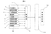
図2は、本装置の制御関係を示すブロック図である。カード/明細票処理機構102、通帳処理機構103、顧客操作部105および紙幣入出金装置1はバス110を介して本体制御部106と接続されており、本体制御部106の制御の下に必要な動作を行う。上記の他に、インタフェース部107と、係員操作部108と、外部記憶装置109ともバス110で接続されており、必要なデータのやり取りを行うが、詳細な説明は省略する。なお、上記各機構、構成部分は、電源部111により電力を供給される。
【0022】
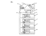
図3は、現金自動取引装置101に実装される紙幣入出金装置1の構成を示す図であり、図4は、制御機構を示す図である。紙幣入出金装置1は、紙幣を出し入れする入出金口2と、紙幣の金種や真偽を判別する紙幣判別部3と、入金した紙幣を取引成立までの間一時的に収納する一時保管部4と、紙幣入出金装置1の各構成要素を結び、紙幣を搬送する搬送路5と、紙幣入出金装置1で取り扱う紙幣が収納される紙幣ユニットとを有する。
【0023】
紙幣ユニットはその役割に応じて分類され、例えば紙幣の一部に折れなどが生じていると判断されたリジェクト紙幣を収納する入金庫、入金および出金に合わせて紙幣の金種ごとに収納および放出を行う金種別の紙幣ユニットである収納放出庫、収納放出庫に紙幣を装填しまた収納放出庫から紙幣を回収する装填回収庫がある。
【0024】
本実施例では、図3に示すように最上段に入金庫6を備える。入金された紙幣のうち、折れなどが生じて出金に適さないと判断された紙幣は入金庫6に収納される。2段目および3段目には収納放出庫7を備える。収納放出庫7は金種別に紙幣が収納され、収納された紙幣は出金のときに放出される。例えば2段目は千円札用、3段目は一万円札用の金庫とすることができる。4段目には装填回収庫8を備える。装填回収庫8は、装填および回収を行うために備えられているため、紙幣入出金装置1で取り扱う紙幣を混在して収納および放出することができる紙幣ユニットである必要がある。
【0025】
さらに、紙幣入出金装置1は、金種と紙幣サイズとの対応関係を記憶した記憶部DBを備える。記憶部DBを備えることによって、紙幣の金種を判別することによって紙幣サイズを判別することができる。制御部9は本体制御部106とバス110を介して接続され、本体制御部106からの指令および紙幣入出金装置1の状態検出に応じて紙幣入出金装置1の制御を行い、紙幣入出金装置1の状態を必要に応じて本体制御部に送る。
【0026】
以下、図5乃至図7を用いて、本実施例の紙幣装填について述べる。紙幣装填は、例えば現金自動取引装置101を稼動する前に装置内に紙幣を装填する場合、または、運用時に装填された紙幣の枚数が少なくなったときに装置内に紙幣を補充する場合に紙幣装填が行われる。制御部9は装填モードとなり、下記紙幣装填を行うように各構成要素を制御する。
【0027】
図5に示すように、装填回収庫8内に収納された紙幣は搬送路5に繰り出される。搬送路5に繰り出された紙幣は、図中の矢印方向に搬送され、紙幣判別部3を経由して金種および枚数を確定されて一時保管部4に一度収納される。
【0028】
次に、図6に示すように、一時保管部4に収納された紙幣は、図中の矢印方向に搬送され、紙幣判別部3により紙幣状態を判別され、リジェクト紙幣であれば入金庫6に収納される。リジェクト紙幣でないと判別された紙幣は、その金種ごとに収納放出庫7に収納される。図7に上記紙幣装填のフロー図を示す。
【0029】
次に、図8乃至図10を用いて、本実施例の紙幣回収について述べる。紙幣回収は、例えば営業終了後に現金自動取引装置101内の紙幣を回収する場合、または、運用時に装填された紙幣の枚数が多くなり装置内の紙幣を回収する必要が生じた場合に紙幣回収が行われる。制御部9は回収モードとなり、下記紙幣回収を行うように各構成要素を制御する。
【0030】
図8に示すように、収納放出庫7に収納された紙幣は搬送路5に繰り出される。搬送路5に繰り出された紙幣は図中の矢印方向に搬送され、紙幣判別部3を経由して金種および枚数を確定されて一時保管部4に一度収納される。
【0031】
次に、図9に示すように、一時保管部4に収納された紙幣は図中の矢印方向に搬送され、紙幣判別部3により紙幣状態を判別され、装填回収庫8に収納される。なお、本実施例では、入金庫6に収納されているリジェクト紙幣を回収する場合は装填回収庫8に収納せずに、入金庫6を取り外しそのまま回収する。図10に上記紙幣回収のフロー図を示す。
【0032】
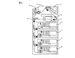
図11は、現金自動取引装置101に実装される紙幣入出金装置1の第2の構成を示す図である。図3に示す紙幣入出金装置とは搬送路5の構成が異なり、装填回収庫8に接続される搬送路は、入金庫6および収納放出庫7と紙幣判別部3を挟んで反対側に位置する。すなわち、装填回収庫8と紙幣判別部3とを結ぶ経路と、収納放出庫7と紙幣判別部8とを結ぶ経路とが異なる経路となる搬送路の構成とする。このように経路が重複せず、装填回収庫8と収納放出庫7とを結ぶ経路上に紙幣判別部3を有するように搬送路5を構成すると、紙幣の装填および回収に一時保管部4を経由せずに連続的に行うことが可能となる。
【0033】
図12および図13を用いて、第2の構成による紙幣装填について述べる。
図12は紙幣装填の動作を示す図であり、図13はフロー図である。装填回収庫8から繰り出された紙幣は、紙幣判別部3を経由して金種および紙幣状態を判別され、金種と枚数が確定される。そして、判別結果に応じて入金庫6および収納放出庫7に収納される。
【0034】
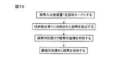
次に、図14および図15を用いて第2の構成による紙幣回収について述べる。
図14は紙幣回収の動作を示す図であり、図15はフロー図である。収納放出庫7から繰り出された紙幣は、紙幣判別部を経由して金種および紙幣状態を判別され、金種と枚数が確定される。そして、装填回収庫8に収納される。装填回収庫8は紙幣入出金装置1から取り外され、係員によって回収される。
【0035】
また、現金自動取引装置101の運用中に精査を行う場合は、回収動作と装填動作とを行うことで、装置内の紙幣枚数を確定させることができる。
【0036】
次に、本実施例の装填回収庫8について詳細に説明する。
紙幣の装填または回収を行う場合には、一つの紙幣収納放出庫内に複数種の紙幣を混在させる必要がある。金種毎に紙幣サイズが大きく異なる場合には、サイズの異なる紙幣を混在して収納できる装填回収庫を必要とする。
【0037】
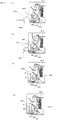
図16は、紙幣入出金装置1に搭載される装填回収庫8の構成を示す上面図である。また、図17は、装填回収庫8に紙幣を収納する状態を表す側面図であり、図18は装填回収庫8から紙幣を放出する状態を表す側面図である。この装填回収庫8は、紙幣を立位状態で水平方向に収納する横置型の金庫であり、収納と分離繰り出しが可能である。
【0038】
紙幣の取込放出機構は、スタック・フィードローラ801と、ピックアップローラ811と、従動回転するバックアップローラ802と、紙幣の収納方向に回転し、繰り出し方向には回転しないゲートローラ803と、ゲートローラ803と同一軸上にあって可撓性の押込み部材が放射状に配置されたブラシローラ804と、分離時とスタック時で位置が変化する分離・スタックガイド805とで構成する。
【0039】
スタック・フィードローラ801は、図示せぬ駆動源からギヤを介して駆動され回転する。収納する紙幣を取込空間へと送り、また放出する紙幣を搬送路5へと送る。バックアップローラ802は、スタック・フィードローラ801に従動して回転し、スタック・フィードローラ801との間に紙幣を挟持して、紙幣を搬送する。ゲートローラ803は、紙幣を収納するときにスタック・フィードローラ801に従動して回転するが、放出するときは回転しない。すなわち、ピックアップローラ811とスタック・フィードローラ801により紙幣を分離し繰り出すときに、放出紙幣に隣接した紙幣はゲートローラ803と接触し、放出紙幣と追従して繰り出されることを防止する。
【0040】
スタック・フィードローラ801とゲートローラ803は取込空間への取込放出口となる。すなわち、紙幣収納の際に、スタック・フィードローラ801とゲートローラ803との挟持がはずれると、紙幣は分離・スタックガイド805との接触を除いて非拘束状態となり、取込空間内に紙幣が取り込まれる。
【0041】
なお、ブラシローラ804は紙幣放出動作を実現するため、約半周分のみしかシートを有していない。紙幣収納のときは、紙幣収納方向に回転することにより放射状に配置されたシートで取込空間にスタックされた紙幣を収納空間へかき出す。紙幣放出のときは、ブラシローラ804はシートを有している部分が取込空間から退避する位置に回転する。したがって、紙幣放出時に放出紙幣がシートと干渉することがない。
【0042】
また、ピックアップローラ811はスタック・フィードローラ801と同期駆動し、さらに、ブラシローラ804はスタック・フィードローラ801に対して逆転駆動する構成であり、駆動源の共用化を図っている。なお、ブラシローラ804は1方向クラッチを介してスタック・フィードローラ801と連結しており、紙幣放出時にブラシローラ804は回転しない。なお、1方向クラッチとは、一方の方向には回転するが、逆の方向には回転しないクラッチであり、図17に示す時計方向には回転するが、反時計方向には回転しない。
【0043】
分離・スタックガイド805は、取込空間側が紙幣案内面となり、紙幣収納時および放出時に紙幣面をガイドする。紙幣収納時は、紙幣案内面が取込放出機構の取込放出口における紙幣進行方向の延長上に沿う位置に配置される。紙幣放出時は、ピックアップローラ806により一枚ずつに分離可能な位置まで紙幣案内面が退避する。
【0044】
収納空間は、底板808と、底板808より上面で収納紙幣の下端を支持するように懸架された底面ベルト807と、押板806と、分離・スタックガイド805と、天板810と、側壁813とで囲まれて形成される。
【0045】
側壁813は紙幣のサイズに合わせて取り付け位置の設定ができる。側壁813の幅は、紙幣の幅方向サイズより2mm〜10mm程度大きい値に設定するのが適当である。また、紙幣入出金装置1が取り扱う最大サイズの紙幣を収納できるように底板808と天板810との間の距離は、最大サイズの紙幣の高さ方向長さよりも大きい値に設定される。
【0046】
装填回収庫8はサイズの異なった紙幣を取り扱う必要があるため、取込放出機構の近傍にスタック補助手段を備えている。スタック補助手段は、収納される紙幣のサイズに関する情報に基づいて制御部9によって制御される。
【0047】
本実施例では、分離・スタックガイド805の上方に収納される紙幣の進行方向先端部を案内するスタック補助部材812が設けられている。
図19にスタック補助部材812の形状を示す。スタック補助部材812は、紙幣の進行方向先端の端線方向に回転軸を有するローラ部812aとL字型の羽根部812bと羽根部812bの先端に所定角度回転可能に接続された可動先端部812cとを備えて構成され、制御部9により回転を制御される。
【0048】
スタック補助部材812は、分離・スタックガイド805の紙幣案内面の延長上にローラ部812aの外周面が位置するように備えられている。
【0049】
ここで、L字型の羽根部812bおよび可動先端部812cについて説明する。ローラ部812aから突出した羽根部812bは、羽根部812bが収納空間側に位置するとき、すなわち、図17に示すところの3つの羽根部812bのうち収納空間側(図中の右側)に位置するとき、羽根部812bの先端が取込放出機構へ向かって曲がった形状である。羽根部812bの折曲部から先端までのローラ部814a外周面と対向する羽根部812b内面と、ローラ部812aの外周面とで囲まれて取込空間を形成し、取込放出機構を通って収納される紙幣の先端部はこの取込空間に案内される。
【0050】
ローラ部812aから羽根部812bの折曲部までの取込空間側の内面は取込空間の奥端面を形成する紙幣端ストッパ部であり、取込放出機構を通って収納される紙幣端の過剰な進行を規制する。
【0051】
羽根部812bの先端には、可動先端部812cが所定角度回転可能に接続される。羽根部812bの折曲部から可動先端部812cの先端までは、取込空間と収納空間との境界を構成する。可動先端部812cは、分離・スタックガイド805との間に空間を確保し、収納紙幣を該空間すなわち取込空間に案内する。
【0052】
可動先端部812cの先端から底板808までの距離は、紙幣入出金装置1で取り扱う最小サイズの紙幣の進行方向長さ、すなわち立位状態で収納された紙幣高さよりも短くし、好ましくは紙幣取込口からの距離が最小サイズの紙幣の進行方向長さよりも短くする。該構成とすると、取込空間に立位状態で取り込まれた紙幣が取込空間内で倒れることを防ぐことができ、安定した収納が可能である。さらに、収納空間に収納された紙幣が取込空間側に倒れこんでくることを防止でき、取り込まれる紙幣と収納された紙幣との間の干渉を防止することができる。
【0053】
スタック補助部材812は、取込空間内に取り込まれた紙幣が立位状態を保つように回転を制御される。大きいサイズの紙幣が取り込まれたときは、取込放出口から紙幣端ストッパ部までの距離が大きな紙幣サイズに対応する長さとなるような回転角度に制御され、小さいサイズの紙幣が取り込まれたときは、取込放出口から紙幣端ストッパ部までの距離が小さな紙幣サイズに対応する長さとなるような回転角度に制御される。
【0054】
ここで、紙幣サイズに対応する長さとなる距離とは、紙幣サイズの進行方向長さよりも若干長い距離のことを示す。若干長い距離とした理由は、取り込まれる紙幣は、搬送状態によって斜行して取込空間に送られる場合があることに起因する。このとき、取込放出口と紙幣端ストッパ部までの距離が紙幣サイズの進行方向長さに等しいと、先端部が紙幣端ストッパ部と衝突して座屈する恐れがある。このような座屈を防ぐために、上記のような制御により取込空間に余裕を持たせている。
【0055】
スタック補助部材812は、図16に示すように紙幣幅方向に複数設けられており、収納される紙幣の上端部を複数箇所で取込空間に案内する。したがって、折れ癖やカール癖を有する紙幣であっても、後続紙幣との干渉を防いで安定して収納することができる。
【0056】
透過センサは発光素子888aと受光素子888bとから構成される。取込放出口近傍に紙幣が存在するときは紙幣によって光が遮られるため、紙幣が取込放出口近傍に存在することを検出する。収納時に光が遮られる時間が長くなると押板806を駆動し、紙幣収納スペースを広くする。
【0057】
このように制御されることによって、スタック補助部材812は、紙幣が装填回収庫8に取り込まれるときには、装填回収庫8の取込空間と収納部とを仕切るように位置し、また、取込空間に取り込まれた紙幣を収納部へ移すときには、紙幣を収納部へ移送可能なように移動する。
【0058】
また、スタック補助部材812の紙幣端ストッパ部は取込空間に取り込まれる紙幣のサイズに応じて変位してサイズの異なる紙幣を収納可能としている。
【0059】
すなわち、スタック補助部材812は、紙幣が装填回収庫8に取り込まれるときには、装填回収庫8の取込空間と収納部とを仕切るように位置し、また、取込空間に取り込まれた紙幣を収納部へ移すときには、紙幣を収納部へ移送可能なように移動する仕切部材と、取込空間に取り込まれる紙幣のサイズに応じて変位する規制部材とを備える構成としてもよい。
【0060】
しかし、本実施例のように仕切部材と規制部材とを一体に備えることによってスタック補助部材812の一体としての制御が可能となる。
【0061】
図18に示すように、装填回収庫8から紙幣を放出する際には、分離・スタックガイド805およびスタック補助部材812は、紙幣取込のときと異なり収納空間から遠ざかるように退避する。収納された紙幣は、押板806により分離・スタックガイド805側に押し付けられ、ピックアップローラ811が回転することによって一枚ずつに分離され取込放出機構を通って装填回収庫8から放出される。
【0062】
次に、図20乃至図23を用いて、装填回収庫8に紙幣を収納する場合の動作について述べる。装填回収庫8に紙幣を装填する場合とは、例えば装置内の紙幣を回収する場合であり、このとき制御部9は紙幣入出金装置1が回収モードとなるよう制御する。
【0063】
なお、装填回収庫8に収納される紙幣のサイズを検出する必要があるため、紙幣サイズ検出手段を備える。本実施例の紙幣サイズ検出手段は、紙幣判別装置3と記憶部DBとを有してなり、収納紙幣のサイズを検出する。紙幣判別部3を通る紙幣は金種を判別されるため、記憶部DBに金種と紙幣サイズとが対応づけられたデータベースを備えることによって、搬送紙幣のサイズを認識することができる。制御部9は、紙幣サイズ検出手段によって検出された紙幣サイズに基づいて以下の制御を行う。以下、サイズが大きい紙幣を収納する場合とサイズが小さい紙幣を収納する場合とに分けて説明する。
【0064】
図20は、サイズの大きい紙幣を収納する場合の動作を示す図である。装填回収庫8に収納される紙幣1000は、紙幣通過センサ889により通過が検出される(図20(a))。紙幣1000は取込放出機構を通って装填回収庫8内に進入する(図20(b))。
【0065】
一方、図23に示すように制御部9は紙幣入出金装置1を回収モードとしたとき、装填回収庫8を収納モードとするよう制御する。収納モードでは、取込放出機構に進入した紙幣をさらに送るようにスタック・フィードローラ用駆動モータ801mを駆動する。紙幣通過センサ889によって紙幣1000の通過が検出されると、制御部9はスタック補助部材用駆動モータ812mを制御し、スタック補助部材812は大きいサイズの紙幣を待ち受けする位置に回転する(図20(c))。
【0066】
さらに紙幣1000は収納放出庫8内部に送られ、スタック・フィードローラ801とゲートローラ803とにより取込空間に進入する。このとき、紙幣1000は、分離・スタックガイド805の紙幣案内面に沿って立位状態を保って送られる。分離・スタックガイド805は、取込放出口から進入する紙幣の進行方向に沿って配置された紙幣案内面を有し、スタック・フィードローラ801とゲートローラ803とによって送られた紙幣1000は分離・スタックガイド805の紙幣案内面に沿って案内される。
【0067】
送られた紙幣1000は、その進行方向先端部がスタック補助部材812の取込空間へと進入し、スタック・フィードローラ801とゲートローラ803との挟持がはずれた後に紙幣1000の進行方向端部が、スタック補助部材812の奥端面の紙幣端ストッパ部と接触する。すなわち、紙幣1000は先端が規制されることで過剰な進行を防がれ、進行方向後端部が底板808と接触して立位状態でスタックされる(図20(d))。取込空間にスタックされた紙幣は、上下端をブラシローラ804およびスタック補助部材812によって押されることで、収納空間側に送られる。収納された紙幣が多くなり、透過センサ888が遮光される時間が長くなると、制御部9は押板用駆動モータ806mを制御し、収納空間が広がるように押板806を移動させ、収納空間を確保する。
【0068】
次にサイズの小さい紙幣を収納する場合について説明する。まず小さい紙幣を収納する場合の従来例による不具合について述べる。装填回収庫8は、大きいサイズの紙幣も収納可能なように、底板808から天板810までの距離は大きいサイズの紙幣に合わせて設定される。
【0069】
ここで、折れ癖やカール癖を有する紙幣を収納する際に、紙幣下端が底板808側に揃って収納することができない場合があった。すなわち、このように癖を有する紙幣は装填回収庫8における収納方向に幅を持つため、取込空間において先に収納された紙幣と分離・スタックガイドとの間に挟まれてしまい、停止してしまう恐れがある。
【0070】
紙幣下端が底板808側に揃って収納されていない場合においては、紙幣入出金装置1が装填モードのときに不具合が生ずる。すなわち、装填回収庫8から紙幣を放出するとき、取込放出口近傍に備えられたピックアップローラ811によって紙幣を一枚ずつ分離するため、取込放出口側に紙幣端部が不揃いの場合、ピックアップローラ811によって紙幣を分離することが困難となる。
【0071】
一方で、ピックアップローラ811は取込放出口近傍に配置される必要がある。取込放出口から離れた位置にピックアップローラ811を配置すると、紙幣がピックアップローラ811によって搬送力を与えられる位置と取込放出口の位置との距離が大きくなり、紙幣端部を取込放出口へ案内することが困難となる不具合が生じる。
【0072】
また、紙幣を立位で収納する場合には、上記不具合に加えて次に示すような課題がある。収納される紙幣の立位状態を保つためには、紙幣の上端を支持する必要がある。しかし、紙幣サイズが異なると上端の位置が異なるために、紙幣サイズに対応した支持部材を設ける必要がある。
【0073】
そこで、以下に示すようにサイズの小さい紙幣を収納する。
図21は、サイズの小さい紙幣を収納する場合の動作を示す図である。装填回収庫8に収納される紙幣1000は、紙幣通過センサ889により通過が検出される(図21(a))。紙幣1000は取込放出機構を通って装填回収庫8内に進入する(図21(b))。
【0074】
一方、制御部9は紙幣入出金装置1を回収モードとしたとき、装填回収庫8を収納モードとするよう制御する。収納モードでは、取込放出機構に進入した紙幣をさらに送るようにスタック・フィードローラ用駆動モータ801mを駆動する。紙幣通過センサ889によって紙幣1000の通過が検出されると、紙幣通過センサ889によって紙幣1000の通過が検出されると、制御部9はスタック補助部材用駆動モータ812mを制御し、スタック補助部材812は小さいサイズの紙幣を待ち受けする位置に回転する(図21(c))。
【0075】
さらに紙幣1000は収納放出庫8内部に送られ、スタック・フィードローラ801とゲートローラ803とにより取込空間に進入する。このとき、紙幣1000は、分離・スタックガイド805の紙幣案内面に沿って立位状態を保って送られる。分離・スタックガイド805は、取込放出口から進入する紙幣の進行方向に沿って配置された紙幣案内面を有し、スタック・フィードローラ801とゲートローラ803とによって送られた紙幣1000は分離・スタックガイド805に沿って案内される。
【0076】
送られた紙幣1000は、その進行方向先端部がスタック補助部材812の取込空間へと進入し、スタック・フィードローラ801とゲートローラ803との挟持がはずれた後に紙幣1000の進行方向端部が、スタック補助部材812の奥端面の紙幣端ストッパ部と接触する。すなわち、紙幣1000は先端が規制されることで過剰な進行を防がれ、進行方向後端部が底板808と接触して立位状態でスタックされる(図21(d))。取込空間にスタックされた紙幣は、上下端をブラシローラ804およびスタック補助部材812によって押されることで、収納空間側に送られる。取込空間にスタックされた紙幣は、上下端をブラシローラ804およびスタック補助部材812によって押されることで、収納空間側に送られる。収納された紙幣が多くなり、透過センサ888が遮光される時間が長くなると、制御部9は押板用駆動モータ806mを制御し、収納空間が広がるように押板806を移動させ、収納空間を確保する。
【0077】
上記の例では、スタック補助部材812が収納紙幣の進行方向の先端部を規制することで、紙幣の過剰な進行を防ぐことができ、小さいサイズの紙幣を収納する場合でも、進行方向後端部が底板808側に揃って紙幣を収納することができる。
【0078】
したがって、装填回収庫8から紙幣を放出する場合でも、紙幣を一枚ずつに分離でき、安定的な放出動作が可能である。また、可動先端部812cと底板808との間の距離は、装置で取り扱う最小の紙幣のサイズより短く設定されているため、取込空間に取り込まれた紙幣と収納空間に収納された紙幣との干渉を防ぐことができる。
【0079】
図22は、本実施例の収納動作を示すフロー図である。紙幣判別部3で金種を判別され、紙幣サイズが判別された紙幣が、紙幣通過センサ889により検出されると、制御部9は判別された紙幣サイズの情報に基づいてスタック補助部材812を制御する。
【0080】
図24は、装填回収庫8に備えられるスタック補助手段の他の例を示す図である。この例では、制御部9は駆動原DMを制御し、スタック補助部材812の位置を紙幣サイズに応じて紙幣進行方向に変化させる。またブラシを有するローラ部は図中の反時計回りに連続的に回転することにより、取り込まれた紙幣を収納空間へ送る。
【0081】
以上、本実施例では、リジェクト紙幣を入金するために入金庫を用い、金種別の紙幣ユニットとして収納放出庫を用いた紙幣入出金装置の例を示したが、本例の装填回収庫は入金庫および収納放出庫としての利用にも用いることが可能である。装填回収庫は少なくとも1つ備えていれば一括して装填・回収・精査を行うことができるため、全ての紙幣ユニットを装填回収庫としても差し支えない。
【0082】
また、ここでは紙幣を立位で収納する横置き型の紙幣ユニットについて説明したが、紙幣を水平に集積する縦置き型の紙幣ユニットにも適用できる。すなわち、紙幣ユニット内へ進入する紙幣が水平方向に送られる場合でも、過剰な進行を規制するスタック補助手段を設けることによって、整列性を保った集積ができる。
【0083】
ただ、立位で収納する場合は、重力によって紙幣ユニットにおける収納空間および取込空間の底面がガイドとなり、収納紙幣の下端が底面に揃うという作用がある。そのため、紙幣放出方向の紙幣端が揃っているために紙幣の放出が容易になる。
【0084】
このように、本実施例によれば、一つの装填回収庫にサイズの異なる紙幣を混在して収納することが可能となる。また、サイズの異なる紙幣を取り扱う紙幣入出金装置で、一括して装填・回収・精査を行うことができる。
【0085】
【発明の効果】
本発明によれば、サイズの異なる紙幣を取り扱い、装填および回収を一括して行うことが可能な紙幣入出金装置および現金自動取引装置を提供することができる。
【図面の簡単な説明】
【図1】 本発明を適用する現金自動取引装置の外観を示す図である。
【図2】 本発明を適用する現金自動取引装置の制御機構を示す図である。
【図3】 紙幣入出金装置の構成を示す図である。
【図4】 本実施例の紙幣入出金装置の制御機構を示す図である。
【図5】 本実施例の紙幣装填の動作を示す図である。
【図6】 本実施例の紙幣装填の動作を示す図である。
【図7】 本実施例の紙幣装填のフロー図である。
【図8】 本実施例の紙幣回収の動作を示す図である。
【図9】 本実施例の紙幣回収の動作を示す図である。
【図10】 本実施例の紙幣回収のフロー図である。
【図11】 紙幣入出金装置の第2の構成を示す図である。
【図12】 第2の構成による紙幣装填の動作を示す図である。
【図13】 第2の構成による紙幣装填のフロー図である。
【図14】 第2の構成による紙幣回収の動作を示す図である。
【図15】 第2の構成による紙幣回収のフロー図である。
【図16】 紙幣入出金装置に搭載される装填回収庫の上面図である。
【図17】 装填回収庫に紙幣を収納する状態を表す側面図である。
【図18】 装填回収庫から紙幣を放出する状態を示す側面図である。
【図19】 スタック補助部材の形状を示す図である。
【図20】 装填回収庫に紙幣を収納する動作を示す図である。
【図21】 装填回収庫に紙幣を収納する動作を示す図である。
【図22】 装填回収庫に紙幣を収納するフロー図である。
【図23】 装填回収庫に紙幣を収納、放出する制御機構を示す図である。
【図24】 スタック補助手段の他の実施例を示す図である。
【符号の説明】
1…紙幣入出金装置、3…紙幣判別部、7…収納放出庫、8…装填回収庫、9…制御部、101…現金自動取引装置、812…スタック補助部材、812a…ローラ部、812b…羽根部、812c…可動先端部、889…紙幣通過センサ、DB…記憶部。[0001]
BACKGROUND OF THE INVENTION
The present invention relates to a banknote deposit / withdrawal apparatus and an automatic cash transaction apparatus that utilize a deposited banknote as a withdrawal banknote.
[0002]
[Prior art]
2. Description of the Related Art A banknote depositing / withdrawing apparatus in an automatic cash transaction apparatus used in a financial institution is provided with a storage / discharging box that stores a deposited banknote and discharges it as a withdrawal banknote at the time of withdrawal, that is, a so-called banknote recirculation.
[0003]
By the way, when handling domestic and foreign banknotes, the types of banknotes to be handled increase, and it is necessary to handle banknotes having greatly different sizes and rigidity. Japanese Patent Application Laid-Open No. 2000-187752 includes a storage / discharging container in which a top plate is provided so as to be adjustable in the vertical direction according to the length in the short side direction of banknotes stored in order to handle banknotes of different sizes. A banknote deposit and withdrawal device is disclosed. Japanese Patent Application Laid-Open No. 7-257805 discloses a paper sheet stacking apparatus provided with a stacking guide plate that is position-adjusted according to the banknote size in order to store paper sheets of different sizes.
[0004]
[Problems to be solved by the invention]
In the banknote depositing / withdrawing apparatus described in JP 2000-187752 A, banknotes of different sizes cannot be mixed and stored in the storage / discharge box. For example, when the position of the top plate is adjusted so as to handle a small-size banknote, when trying to store a large-size banknote, the end portion in the traveling direction of the stored banknote collides with the top plate, and there is sufficient storage space. Can not be secured. On the other hand, when the position of the top plate is adjusted so as to handle a large-size banknote, when trying to store a small-size banknote, it is necessary to move away from the holding of the roller until the traveling direction end of the banknote collides with the top plate. Since the distance is too long, it becomes difficult to store the storage and release container while maintaining alignment. For example, in the case of the European integrated currency Euro, the smallest euro banknote has a length in the longitudinal direction of 120 mm and a short direction length of 60 mm, whereas the largest euro banknote has a length of 170 mm and 85 mm, respectively. In this way, banknotes having a large size difference cannot be mixed and stored in the same banknote unit.
[0005]
By the way, when loading banknotes into an automatic teller machine, the banknotes to be loaded are packed in one loading and collecting box, and the number of banknotes packed in the loading and collecting box is confirmed through the discrimination unit. It is transported and loaded into a denomination banknote unit. Further, when collecting banknotes, an empty loading / recovery box is mounted, and the bills are conveyed from the denominated banknote unit via the discrimination section while being conveyed and stored in the loading / recovery box.
[0006]
In this way, when loading or collecting banknotes, it is necessary to mix a plurality of types of banknotes in a single loading / recovery box. In the apparatus described in Japanese Patent Laid-Open No. 2000-187752, banknotes are devoted to each denomination. When the sizes differ greatly, it was not possible to load and collect all at once. In addition, since it is necessary to perform a collecting operation and a loading operation even when conducting a scrutiny during operation, a scrutiny cannot be performed with the conventional configuration.
[0007]
This invention is made | formed in view of the said subject, and it aims at providing the banknote depositing / withdrawing apparatus and cash automatic transaction apparatus which can handle the banknote from which size differs, and can perform loading and collection | collection collectively. .
[0008]
[Means for Solving the Problems]
In order to achieve the above object, the banknote depositing / dispensing device according to the present invention has, for example, a banknote unit that first stores and discharges banknotes, and
Banknote size detection means for detecting the size of banknotes stored in the banknote unit;
A bill passage sensor for detecting passage of bills conveyed to the bill unit;
A control unit for controlling each component,
The banknote unit includes stack auxiliary means for regulating excessive progression of banknotes entering the banknote unit,
The control unit is to control the stack assisting unit based on the information on the banknote size detected by the banknote size detecting unit after the passage of the banknote is detected by the banknote passing sensor.
[0009]
The second feature is that in the banknote depositing and dispensing device having the first feature, the bill size detecting means has a bill discrimination unit for discriminating the denomination of the bill, and a database in which the denomination and the bill size are associated with each other. And a storage unit.
[0010]
The third feature is that, in the banknote depositing / dispensing apparatus having the first feature, the bill unit stores bills in a standing position.
[0011]
The fourth feature is that in the banknote depositing and dispensing device having the first feature, the control unit controls the stack auxiliary means so that the stack auxiliary means retracts to a position where it does not interfere with the released banknote when the banknote is released. It is in.
[0012]
The fifth feature is a loading / collecting warehouse in which a plurality of bill units are provided in the bill depositing / withdrawing apparatus having the first feature, and bills are collected from other bill units, and bills are loaded into other bill units. There is.
[0013]
The sixth feature is a banknote depositing / withdrawing apparatus having the fifth feature, wherein a plurality of banknote units are provided, and the plurality of banknote units store banknotes that are not suitable for withdrawal and banknotes by denomination. And a storage / release container for discharging, and a bill collection / recovery unit for collecting banknotes from the storage / discharge container and loading banknotes into the storage / release container,
A bill discriminating unit for discriminating the denomination of the bill;
A transport path that connects each banknote unit and banknote discriminating section and transports banknotes,
The conveyance path is to have a bill discriminating unit on a path connecting the loading / recovery box and the storage / discharge box.
[0014]
According to a seventh feature, in the banknote depositing / dispensing device having the first feature, the banknote unit constitutes a take-out / release port and feeds the banknote, and the banknote sent to the banknote unit by the roller is guided in the traveling direction. A stack guide having a bill guide surface,
The stack auxiliary means includes a stack auxiliary member that has a bill edge stopper portion that regulates a leading end portion in a traveling direction of a bill to be stored and forms an intake space,
The control unit is to control the distance from the take-in / discharge port of the bill end stopper unit.
[0015]
The eighth feature is that in the banknote depositing / dispensing device having the seventh feature, the stack auxiliary member includes a roller portion having a rotation axis in an end line direction at a front end of the bill in a traveling direction, and a blade portion projecting radially from the roller portion. And a movable tip connected to the tip of the blade portion so as to be rotatable by a predetermined angle,
The blade part is that the tip part is bent in an L shape toward the intake / discharge port.
[0016]
A ninth feature is that in the banknote depositing and dispensing device having the eighth feature, a plurality of stack auxiliary members are provided in the direction of the rotation axis of the roller portion.
[0017]
A tenth feature is a banknote depositing / dispensing device including a banknote unit that stacks banknotes in a horizontal position in a standing position, and a transport device that transports banknotes to the banknote unit.
When taking in the banknote unit the banknote conveyed with the said conveying apparatus, it positions so that a taking-in space and a storage part may be partitioned in the said banknote unit, and the banknote taken in into the said taking-in space is said storing part A partition member that moves so that the bill can be transferred,
When a bill is taken into the bill unit, a regulating member that is displaced according to the size of the bill to be taken in contact with the tip of the bill and regulates the progression,
It is to be able to store bills of different sizes in the storage unit.
[0018]
The eleventh feature is that in the banknote depositing and dispensing device having the tenth feature, the partition member and the regulating member are integrally formed.
[0019]
Moreover, the automatic teller machine of this invention was equipped with the banknote depositing / withdrawing apparatus which has the said characteristic.
[0020]
DETAILED DESCRIPTION OF THE INVENTION
Hereinafter, an embodiment of the present invention will be described in detail.
FIG. 1 is a diagram showing the appearance of an automatic teller machine to which the present invention is applied. The
[0021]
FIG. 2 is a block diagram showing the control relationship of this apparatus. The card / detail
[0022]
FIG. 3 is a diagram showing a configuration of the banknote depositing / withdrawing
[0023]
The banknote units are classified according to their roles. For example, a deposit box for storing rejected banknotes that are judged to be broken in a part of the banknotes, and storing and storing each banknote denomination according to deposit and withdrawal. There are a storage and discharge box which is a denomination-type banknote unit for discharging, and a loading and collecting box for loading banknotes into the storage and discharge box and collecting banknotes from the storage and discharge box.
[0024]
In the present embodiment, as shown in FIG. Of the deposited banknotes, banknotes that are determined to be unsuitable for withdrawal due to folding or the like are stored in the
[0025]
Furthermore, the banknote depositing / withdrawing
[0026]
Hereinafter, bill loading according to the present embodiment will be described with reference to FIGS. The bill loading is performed when, for example, bills are loaded into the device before the
[0027]
As shown in FIG. 5, the banknotes stored in the loading /
[0028]
Next, as shown in FIG. 6, the banknotes stored in the
[0029]
Next, the banknote collection of the present embodiment will be described with reference to FIGS. The banknote collection is performed when, for example, the banknotes in the
[0030]
As shown in FIG. 8, the banknotes stored in the storage /
[0031]
Next, as shown in FIG. 9, the banknotes stored in the
[0032]
FIG. 11 is a diagram showing a second configuration of the banknote depositing / withdrawing
[0033]
The bill loading according to the second configuration will be described with reference to FIGS.
FIG. 12 is a view showing the bill loading operation, and FIG. 13 is a flowchart. The banknotes drawn out from the loading /
[0034]
Next, the banknote collection | recovery by a 2nd structure is described using FIG. 14 and FIG.
FIG. 14 is a diagram showing the bill collecting operation, and FIG. 15 is a flowchart. The banknotes drawn out from the storage /
[0035]
Moreover, when performing a close examination during operation | movement of the
[0036]
Next, the load collection | recovery store | warehouse |
When loading or collecting banknotes, it is necessary to mix a plurality of types of banknotes in one banknote storage / release box. When the banknote size is greatly different for each denomination, a loading / recovery box capable of storing a mixture of banknotes of different sizes is required.
[0037]
FIG. 16 is a top view showing the configuration of the loading /
[0038]
The banknote take-in / release mechanism includes a stack /
[0039]
The stack /
[0040]
The stack /
[0041]
Note that the
[0042]
The
[0043]
The separation /
[0044]
The storage space includes a
[0045]
The attachment position of the
[0046]
Since the loading /
[0047]
In the present embodiment, a stack
FIG. 19 shows the shape of the stack
[0048]
The stack
[0049]
Here, the L-shaped blade portion 812b and the
[0050]
The inner surface of the take-up space side from the
[0051]
A
[0052]
The distance from the front end of the movable
[0053]
The rotation of the stack
[0054]
Here, the distance corresponding to the banknote size indicates a distance slightly longer than the length of the banknote size in the traveling direction. The reason for the slightly longer distance is due to the fact that the bill to be taken may be skewed depending on the transport state and sent to the taking-in space. At this time, if the distance between the take-in and discharge port and the bill end stopper is equal to the length of the bill size in the traveling direction, the leading end may collide with the bill end stopper and buckle. In order to prevent such buckling, an allowance is provided in the take-in space by the above control.
[0055]
As shown in FIG. 16, a plurality of stack
[0056]
The transmission sensor includes a
[0057]
By being controlled in this manner, the stack
[0058]
Moreover, the banknote edge stopper part of the stack
[0059]
That is, the stack
[0060]
However, by integrally providing the partition member and the regulating member as in this embodiment, the stack
[0061]
As shown in FIG. 18, when the banknote is discharged from the loading /
[0062]
Next, the operation for storing banknotes in the loading /
[0063]
In addition, since it is necessary to detect the size of the banknote accommodated in the loading collection | recovery store | warehouse |
[0064]
FIG. 20 is a diagram illustrating an operation when storing a large banknote. The
[0065]
On the other hand, as shown in FIG. 23, when the banknote depositing /
[0066]
Further, the
[0067]
The forward end of the
[0068]
Next, the case where a small banknote is accommodated will be described. First, a problem with the conventional example when storing small banknotes will be described. In the loading /
[0069]
Here, when storing banknotes having folds or curls, the lower end of the banknotes may not be stored on the
[0070]
In the case where the lower end of the banknotes is not stored on the
[0071]
On the other hand, the
[0072]
Further, when storing banknotes in a standing position, there are the following problems in addition to the above problems. In order to maintain the standing state of the banknote to be stored, it is necessary to support the upper end of the banknote. However, since the position of the upper end differs when the bill size is different, it is necessary to provide a support member corresponding to the bill size.
[0073]
Therefore, small banknotes are stored as shown below.
FIG. 21 is a diagram illustrating an operation when a small banknote is stored. Passage of the
[0074]
On the other hand, when the banknote depositing /
[0075]
Further, the
[0076]
The forward end of the
[0077]
In the above example, the stack
[0078]
Therefore, even when the banknotes are discharged from the
[0079]
FIG. 22 is a flowchart showing the storing operation of this embodiment. When the
[0080]
FIG. 24 is a view showing another example of the stack auxiliary means provided in the loading /
[0081]
As described above, in the present embodiment, an example of a banknote depositing / dispensing device using a deposit box for depositing rejected banknotes and using a storage / discharging box as a banknote unit of each type of money has been shown. It can also be used as a safe and a storage and discharge box. If at least one loading / recovery box is provided, loading / recovery / scrutiny can be performed in a lump, so that all banknote units may be used as a loading / recovery box.
[0082]
Moreover, although the horizontal type banknote unit which stores a banknote in a standing position was demonstrated here, it is applicable also to the vertical type banknote unit which accumulate | stacks a banknote horizontally. That is, even when banknotes entering the banknote unit are fed in the horizontal direction, stacking with alignment can be maintained by providing a stack auxiliary means for restricting excessive progress.
[0083]
However, when storing in a standing position, the bottom surfaces of the storage space and the taking-in space in the banknote unit serve as guides due to gravity, and the lower end of the stored banknotes is aligned with the bottom surface. Therefore, since the banknote edges in the banknote discharge direction are aligned, it is easy to discharge banknotes.
[0084]
Thus, according to the present embodiment, it is possible to store bills of different sizes in a single loading / recovery box. In addition, a bill depositing / dispensing apparatus that handles bills of different sizes can be loaded, collected, and examined in a batch.
[0085]
【The invention's effect】
ADVANTAGE OF THE INVENTION According to this invention, the banknote depositing / withdrawing apparatus and cash automatic transaction apparatus which can handle the banknote from which size differs and can perform loading and collection | collection collectively can be provided.
[Brief description of the drawings]
FIG. 1 is a diagram showing an external appearance of an automatic teller machine to which the present invention is applied.
FIG. 2 is a diagram showing a control mechanism of an automatic teller machine to which the present invention is applied.
FIG. 3 is a diagram showing a configuration of a banknote deposit and withdrawal device.
FIG. 4 is a diagram illustrating a control mechanism of the banknote depositing / dispensing device according to the present embodiment.
FIG. 5 is a diagram illustrating a bill loading operation according to the embodiment.
FIG. 6 is a diagram illustrating an operation of bill loading according to the present embodiment.
FIG. 7 is a flowchart of bill loading according to the present embodiment.
FIG. 8 is a diagram showing a bill recovery operation of the present embodiment.
FIG. 9 is a diagram illustrating the bill collection operation of the embodiment.
FIG. 10 is a flow chart of banknote collection according to the present embodiment.
FIG. 11 is a diagram showing a second configuration of the banknote deposit and withdrawal device.
FIG. 12 is a diagram showing a bill loading operation according to the second configuration.
FIG. 13 is a flowchart of bill loading according to the second configuration.
FIG. 14 is a diagram showing an operation of collecting banknotes according to the second configuration.
FIG. 15 is a flowchart of banknote collection according to the second configuration.
FIG. 16 is a top view of a loading / recovery box mounted on the banknote depositing / withdrawing apparatus.
FIG. 17 is a side view showing a state in which banknotes are stored in a loading and collecting box.
FIG. 18 is a side view showing a state in which banknotes are discharged from the loading collection box.
FIG. 19 is a view showing the shape of a stack auxiliary member.
FIG. 20 is a diagram showing an operation of storing banknotes in a loading / recovery box.
FIG. 21 is a diagram illustrating an operation of storing banknotes in a loading / recovery box.
FIG. 22 is a flowchart for storing banknotes in a loading / recovery box.
FIG. 23 is a diagram showing a control mechanism for storing and discharging banknotes in a loading and collecting box.
FIG. 24 is a view showing another embodiment of the stack auxiliary means.
[Explanation of symbols]
DESCRIPTION OF
Claims (14)
紙幣を前記紙幣ユニット内に取り込むための取込空間と、前記取込空間近傍に位置して回転する規制部材とを備え、前記規制部材が前記紙幣ユニットに取り込まれる紙幣の進行方向側前端部を規制して、前記紙幣の後端を前記紙幣ユニットの内部面に揃えることを特徴とする紙幣入出金装置。In the banknote unit that takes in banknotes one by one from the outside,
A front end of the banknote in which a banknote is taken into the banknote unit, and a regulating member that rotates in the vicinity of the taking-up space, and the bank is taken into the banknote unit. The banknote depositing / withdrawing apparatus is characterized by regulating and aligning the rear end of the banknote with the inner surface of the banknote unit.
紙幣を前記紙幣ユニット内に取り込むための取込空間と、前記取込空間近傍に位置して回転する規制部材とを備え、前記取込空間に取り込む紙幣の種類や大きさに対応して前記規制部材の回転を制御することで前記紙幣の進行を規制して、前記紙幣の後端を前記紙幣ユニットの内部面に揃えることを特徴とする紙幣入出金装置。In the banknote unit that takes in banknotes one by one from the outside,
The regulation includes a taking-in space for taking in banknotes into the banknote unit, and a regulating member that rotates in the vicinity of the taking-in space and corresponds to the type and size of the banknote to be taken into the taking-in space. The banknote depositing / withdrawing apparatus characterized by controlling the rotation of the member to regulate the progress of the banknote and aligning the rear end of the banknote with the inner surface of the banknote unit.
Priority Applications (5)
| Application Number | Priority Date | Filing Date | Title |
|---|---|---|---|
| JP2002000229A JP3861007B2 (en) | 2002-01-07 | 2002-01-07 | Banknote deposit and withdrawal device and automatic cash transaction device |
| US10/279,929 US6889897B2 (en) | 2002-01-07 | 2002-10-25 | Bill receiving/paying device and automated cash transaction apparatus |
| EP20020025072 EP1326215A3 (en) | 2002-01-07 | 2002-11-12 | Bill receiving/paying device and automated cash transaction apparatus |
| KR10-2002-0071827A KR100514031B1 (en) | 2002-01-07 | 2002-11-19 | Bill receiving/paying device and automated cash transaction apparatus |
| CNB021513856A CN1274569C (en) | 2002-01-07 | 2002-11-20 | Paper money receiving/paying device and automatic cash transcation appts. |
Applications Claiming Priority (1)
| Application Number | Priority Date | Filing Date | Title |
|---|---|---|---|
| JP2002000229A JP3861007B2 (en) | 2002-01-07 | 2002-01-07 | Banknote deposit and withdrawal device and automatic cash transaction device |
Publications (3)
| Publication Number | Publication Date |
|---|---|
| JP2003203262A JP2003203262A (en) | 2003-07-18 |
| JP2003203262A5 JP2003203262A5 (en) | 2006-09-21 |
| JP3861007B2 true JP3861007B2 (en) | 2006-12-20 |
Family
ID=19190460
Family Applications (1)
| Application Number | Title | Priority Date | Filing Date |
|---|---|---|---|
| JP2002000229A Expired - Fee Related JP3861007B2 (en) | 2002-01-07 | 2002-01-07 | Banknote deposit and withdrawal device and automatic cash transaction device |
Country Status (5)
| Country | Link |
|---|---|
| US (1) | US6889897B2 (en) |
| EP (1) | EP1326215A3 (en) |
| JP (1) | JP3861007B2 (en) |
| KR (1) | KR100514031B1 (en) |
| CN (1) | CN1274569C (en) |
Families Citing this family (27)
| Publication number | Priority date | Publication date | Assignee | Title |
|---|---|---|---|---|
| JP3931112B2 (en) * | 2002-06-05 | 2007-06-13 | 日立オムロンターミナルソリューションズ株式会社 | A bill handling apparatus, an automatic transaction apparatus, and a change withdrawal method for an automatic transaction apparatus. |
| JP4292012B2 (en) * | 2003-02-10 | 2009-07-08 | 日立オムロンターミナルソリューションズ株式会社 | Banknote deposit and withdrawal device |
| JP2005010967A (en) * | 2003-06-18 | 2005-01-13 | Hitachi Ltd | Banknote deposit and withdrawal device and automatic cash transaction device |
| JP2006079187A (en) * | 2004-09-07 | 2006-03-23 | World Techno:Kk | Processor for print paper sheet |
| DE102004061467A1 (en) * | 2004-12-17 | 2006-06-29 | Wincor Nixdorf International Gmbh | Banknote system |
| JP2007091436A (en) * | 2005-09-30 | 2007-04-12 | Hitachi Omron Terminal Solutions Corp | Automatic cash transaction equipment with banknote deposit and withdrawal device |
| JP4267045B2 (en) * | 2006-09-06 | 2009-05-27 | キヤノン株式会社 | Sheet stacking apparatus and image forming apparatus |
| JP5028924B2 (en) * | 2006-09-15 | 2012-09-19 | 沖電気工業株式会社 | Media processing device |
| KR100832123B1 (en) * | 2006-11-27 | 2008-05-27 | 엘지엔시스(주) | Media sorting device and method, and media dispenser using the same |
| JP4368888B2 (en) | 2006-12-15 | 2009-11-18 | 日立オムロンターミナルソリューションズ株式会社 | Paper sheet storage and paper sheet handling device |
| DE102008018961A1 (en) * | 2008-04-15 | 2009-10-29 | Wincor Nixdorf International Gmbh | Single-sheet handling device for entering rectangular single sheets into a container |
| DE102008018935A1 (en) | 2008-04-15 | 2009-10-22 | Wincor Nixdorf International Gmbh | Single-sheet handling device for inputting and outputting rectangular individual sheets, in particular banknotes, into or out of a container |
| JP4804504B2 (en) | 2008-05-09 | 2011-11-02 | 日立オムロンターミナルソリューションズ株式会社 | Bill deposit / withdrawal apparatus, automatic cash transaction apparatus, and bill accumulation method |
| US8733634B1 (en) * | 2008-06-27 | 2014-05-27 | Diebold Self-Service Systems, Division Of Diebold, Incorporated | Banking system controlled responsive to data bearing records |
| JP5335389B2 (en) * | 2008-11-29 | 2013-11-06 | 日立オムロンターミナルソリューションズ株式会社 | Paper sheet handling equipment |
| IT1392251B1 (en) * | 2008-12-02 | 2012-02-22 | Cts Electronics S P A | DEPOSIT, DEPOSIT AND DEPOSIT FOR BANKNOTES, CHECKS AND / OR DOCUMENTS |
| JP5386982B2 (en) * | 2008-12-26 | 2014-01-15 | シンフォニアテクノロジー株式会社 | Paper sheet processing equipment |
| DE102009006810A1 (en) * | 2009-01-30 | 2010-08-05 | Wincor Nixdorf International Gmbh | Apparatus and method for depositing and / or disbursing at least banknotes of a first denomination and banknotes of a second denomination |
| WO2011036806A1 (en) * | 2009-09-28 | 2011-03-31 | グローリー株式会社 | Storage and paper sheet processing device |
| DE102009058519A1 (en) * | 2009-12-16 | 2011-06-22 | WINCOR NIXDORF International GmbH, 33106 | Device for handling notes of value |
| DE102010004581A1 (en) * | 2010-01-14 | 2011-07-21 | WINCOR NIXDORF International GmbH, 33106 | Device for handling notes of value |
| FR2961417A1 (en) * | 2010-06-17 | 2011-12-23 | Solystic | DEVICE FOR STACKING FLAT OBJECTS ON THE EDGE, ITS STEERING METHOD, AND POSTAL SORTING MACHINE EQUIPPED WITH AT LEAST ONE SUCH DEVICE |
| FR2984772B1 (en) * | 2011-12-22 | 2014-02-14 | Solystic | DEVICE AND METHOD FOR STACKING AND AUTOMATICALLY LOADING SINGLE-PANEL OBJECTS IN A MULTI-COMPARTMENT BIN, POSTAL SORTING MACHINE, AND POSTAL SORTING METHOD |
| US9016682B2 (en) * | 2013-01-24 | 2015-04-28 | Ncr Corporation | Item location |
| JP6079472B2 (en) * | 2013-06-25 | 2017-02-15 | 沖電気工業株式会社 | Automatic transaction equipment |
| EP3246882B1 (en) * | 2016-05-17 | 2023-08-02 | ATEC AP Co., Ltd. | Financial device and method for controlling the same |
| KR101868226B1 (en) | 2016-09-22 | 2018-06-18 | 효성티앤에스 주식회사 | Apparatus for stacking paper money |
Family Cites Families (13)
| Publication number | Priority date | Publication date | Assignee | Title |
|---|---|---|---|---|
| JPH0666074B2 (en) * | 1983-04-04 | 1994-08-24 | 株式会社東芝 | Sorting device |
| JPS59205694A (en) | 1983-05-09 | 1984-11-21 | 株式会社東芝 | Sheet paper withdrawer |
| KR890004965B1 (en) * | 1984-08-06 | 1989-12-02 | 가부시기가이샤 도시바 | Automatic Bank Transaction System |
| US4707843A (en) | 1985-05-03 | 1987-11-17 | American Coin Currency Equipment Corporation | Relating to microprocessor controlled cash counting apparatus |
| DE19525168C2 (en) | 1995-07-11 | 1997-05-28 | Koenig & Bauer Albert Ag | Paddle wheel for laying folded products |
| US6493461B1 (en) * | 1998-03-17 | 2002-12-10 | Cummins-Allison Corp. | Customizable international note counter |
| EP2378491A3 (en) | 1998-06-26 | 2016-01-20 | Hitachi-Omron Terminal Solutions, Corp. | Bill deposit/withdrawal machine |
| JP3183288B2 (en) * | 1998-10-12 | 2001-07-09 | 株式会社日立製作所 | Bill receiving / dispensing device |
| GB9823337D0 (en) | 1998-10-23 | 1998-12-23 | Rue De Int Ltd | Sheet stacking apparatus |
| US6227446B1 (en) * | 1998-11-23 | 2001-05-08 | Diebold, Incorporated | Automated transaction machine note storage and delivery mechanism |
| JP4135238B2 (en) * | 1998-12-08 | 2008-08-20 | 日立オムロンターミナルソリューションズ株式会社 | Banknote deposit and withdrawal machine |
| KR100436939B1 (en) | 1999-02-04 | 2004-06-23 | 오브체스토브 에스 오르가니첸노이 오트베트스트벤노스티쥬 퍼마 "데이타 센터" | Method for determining the authenticity, the value and the decay level of banknotes, and sorting and counting device |
| DE10014440A1 (en) | 2000-03-23 | 2001-09-27 | Giesecke & Devrient Gmbh | Sheet processing device for bank notes has turns of stacking wheels synchronized with frequency of separator |
-
2002
- 2002-01-07 JP JP2002000229A patent/JP3861007B2/en not_active Expired - Fee Related
- 2002-10-25 US US10/279,929 patent/US6889897B2/en not_active Expired - Fee Related
- 2002-11-12 EP EP20020025072 patent/EP1326215A3/en not_active Ceased
- 2002-11-19 KR KR10-2002-0071827A patent/KR100514031B1/en not_active Expired - Fee Related
- 2002-11-20 CN CNB021513856A patent/CN1274569C/en not_active Expired - Lifetime
Also Published As
| Publication number | Publication date |
|---|---|
| JP2003203262A (en) | 2003-07-18 |
| CN1431137A (en) | 2003-07-23 |
| US6889897B2 (en) | 2005-05-10 |
| KR20030060756A (en) | 2003-07-16 |
| US20030127509A1 (en) | 2003-07-10 |
| KR100514031B1 (en) | 2005-09-13 |
| EP1326215A3 (en) | 2004-11-24 |
| CN1274569C (en) | 2006-09-13 |
| EP1326215A2 (en) | 2003-07-09 |
Similar Documents
| Publication | Publication Date | Title |
|---|---|---|
| JP3861007B2 (en) | Banknote deposit and withdrawal device and automatic cash transaction device | |
| JP4292012B2 (en) | Banknote deposit and withdrawal device | |
| JP5274999B2 (en) | Banknote handling equipment | |
| JP3914807B2 (en) | Banknote deposit and withdrawal device | |
| JP2005010967A (en) | Banknote deposit and withdrawal device and automatic cash transaction device | |
| JP4804504B2 (en) | Bill deposit / withdrawal apparatus, automatic cash transaction apparatus, and bill accumulation method | |
| CN103988237A (en) | Currency note deposit/withdrawal device and currency note processing device | |
| JP5664355B2 (en) | Paper sheet processing apparatus and transaction apparatus | |
| JP5484935B2 (en) | Paper sheet processing apparatus and paper sheet processing method | |
| JPH11283074A (en) | Circulation type paper money receiving and paying machine | |
| KR101865141B1 (en) | Paper currency processing device | |
| JP4935216B2 (en) | Media handling device | |
| JP2888715B2 (en) | Banknote deposit and withdrawal machine | |
| JPH0431156B2 (en) | ||
| JP4663380B2 (en) | Small bundle banknote processing machine | |
| JP2007041826A (en) | Banknote deposit and withdrawal device and automatic cash transaction device | |
| JP2020086654A (en) | Coin processing device and automatic transaction device | |
| JP4110183B2 (en) | Bill storage bin | |
| JP2004010346A (en) | Paper sheet transport device, paper sheet storage unit, bill handling device, and automatic cash transaction device | |
| JP2004102669A (en) | Bill treatment device | |
| JP4151212B2 (en) | Paper sheet handling device and method for correcting deviation of paper sheet | |
| JP2023109472A (en) | Paper sheet width aligning device, paper sheet processing device, and paper sheet width aligning method | |
| JP6728762B2 (en) | Media processing device | |
| JPH0755754B2 (en) | Banknote storage device | |
| HK1227158A1 (en) | Paper currency processing device |
Legal Events
| Date | Code | Title | Description |
|---|---|---|---|
| A621 | Written request for application examination |
Free format text: JAPANESE INTERMEDIATE CODE: A621 Effective date: 20041214 |
|
| A711 | Notification of change in applicant |
Free format text: JAPANESE INTERMEDIATE CODE: A712 Effective date: 20050223 |
|
| RD02 | Notification of acceptance of power of attorney |
Free format text: JAPANESE INTERMEDIATE CODE: A7422 Effective date: 20060510 |
|
| RD04 | Notification of resignation of power of attorney |
Free format text: JAPANESE INTERMEDIATE CODE: A7424 Effective date: 20060510 |
|
| A521 | Request for written amendment filed |
Free format text: JAPANESE INTERMEDIATE CODE: A523 Effective date: 20060703 |
|
| A521 | Request for written amendment filed |
Free format text: JAPANESE INTERMEDIATE CODE: A523 Effective date: 20060703 |
|
| A977 | Report on retrieval |
Free format text: JAPANESE INTERMEDIATE CODE: A971007 Effective date: 20060825 |
|
| TRDD | Decision of grant or rejection written | ||
| A01 | Written decision to grant a patent or to grant a registration (utility model) |
Free format text: JAPANESE INTERMEDIATE CODE: A01 Effective date: 20060912 |
|
| A61 | First payment of annual fees (during grant procedure) |
Free format text: JAPANESE INTERMEDIATE CODE: A61 Effective date: 20060925 |
|
| R150 | Certificate of patent or registration of utility model |
Free format text: JAPANESE INTERMEDIATE CODE: R150 |
|
| FPAY | Renewal fee payment (event date is renewal date of database) |
Free format text: PAYMENT UNTIL: 20090929 Year of fee payment: 3 |
|
| FPAY | Renewal fee payment (event date is renewal date of database) |
Free format text: PAYMENT UNTIL: 20100929 Year of fee payment: 4 |
|
| FPAY | Renewal fee payment (event date is renewal date of database) |
Free format text: PAYMENT UNTIL: 20100929 Year of fee payment: 4 |
|
| FPAY | Renewal fee payment (event date is renewal date of database) |
Free format text: PAYMENT UNTIL: 20110929 Year of fee payment: 5 |
|
| FPAY | Renewal fee payment (event date is renewal date of database) |
Free format text: PAYMENT UNTIL: 20120929 Year of fee payment: 6 |
|
| FPAY | Renewal fee payment (event date is renewal date of database) |
Free format text: PAYMENT UNTIL: 20120929 Year of fee payment: 6 |
|
| FPAY | Renewal fee payment (event date is renewal date of database) |
Free format text: PAYMENT UNTIL: 20130929 Year of fee payment: 7 |
|
| LAPS | Cancellation because of no payment of annual fees |