JP3860239B2 - Cruise control system - Google Patents
Cruise control system Download PDFInfo
- Publication number
- JP3860239B2 JP3860239B2 JP34591795A JP34591795A JP3860239B2 JP 3860239 B2 JP3860239 B2 JP 3860239B2 JP 34591795 A JP34591795 A JP 34591795A JP 34591795 A JP34591795 A JP 34591795A JP 3860239 B2 JP3860239 B2 JP 3860239B2
- Authority
- JP
- Japan
- Prior art keywords
- distance
- vehicle
- cruise control
- headway
- control system
- Prior art date
- Legal status (The legal status is an assumption and is not a legal conclusion. Google has not performed a legal analysis and makes no representation as to the accuracy of the status listed.)
- Expired - Fee Related
Links
- 238000004364 calculation method Methods 0.000 claims description 4
- 230000007704 transition Effects 0.000 claims description 4
- 230000003247 decreasing effect Effects 0.000 claims description 3
- 230000001133 acceleration Effects 0.000 description 32
- 230000006870 function Effects 0.000 description 6
- 230000007423 decrease Effects 0.000 description 5
- 230000000694 effects Effects 0.000 description 3
- 238000002485 combustion reaction Methods 0.000 description 2
- 238000010586 diagram Methods 0.000 description 2
- 230000004044 response Effects 0.000 description 2
- 230000003213 activating effect Effects 0.000 description 1
- 238000011161 development Methods 0.000 description 1
- 230000018109 developmental process Effects 0.000 description 1
- 230000007717 exclusion Effects 0.000 description 1
- 230000005484 gravity Effects 0.000 description 1
- 230000010354 integration Effects 0.000 description 1
- 238000012886 linear function Methods 0.000 description 1
- 238000005259 measurement Methods 0.000 description 1
- 238000000034 method Methods 0.000 description 1
- 238000011017 operating method Methods 0.000 description 1
- 230000003287 optical effect Effects 0.000 description 1
Images

Classifications
-
- B—PERFORMING OPERATIONS; TRANSPORTING
- B60—VEHICLES IN GENERAL
- B60W—CONJOINT CONTROL OF VEHICLE SUB-UNITS OF DIFFERENT TYPE OR DIFFERENT FUNCTION; CONTROL SYSTEMS SPECIALLY ADAPTED FOR HYBRID VEHICLES; ROAD VEHICLE DRIVE CONTROL SYSTEMS FOR PURPOSES NOT RELATED TO THE CONTROL OF A PARTICULAR SUB-UNIT
- B60W30/00—Purposes of road vehicle drive control systems not related to the control of a particular sub-unit, e.g. of systems using conjoint control of vehicle sub-units
- B60W30/14—Adaptive cruise control
- B60W30/16—Control of distance between vehicles, e.g. keeping a distance to preceding vehicle
-
- B—PERFORMING OPERATIONS; TRANSPORTING
- B60—VEHICLES IN GENERAL
- B60K—ARRANGEMENT OR MOUNTING OF PROPULSION UNITS OR OF TRANSMISSIONS IN VEHICLES; ARRANGEMENT OR MOUNTING OF PLURAL DIVERSE PRIME-MOVERS IN VEHICLES; AUXILIARY DRIVES FOR VEHICLES; INSTRUMENTATION OR DASHBOARDS FOR VEHICLES; ARRANGEMENTS IN CONNECTION WITH COOLING, AIR INTAKE, GAS EXHAUST OR FUEL SUPPLY OF PROPULSION UNITS IN VEHICLES
- B60K31/00—Vehicle fittings, acting on a single sub-unit only, for automatically controlling vehicle speed, i.e. preventing speed from exceeding an arbitrarily established velocity or maintaining speed at a particular velocity, as selected by the vehicle operator
- B60K31/0008—Vehicle fittings, acting on a single sub-unit only, for automatically controlling vehicle speed, i.e. preventing speed from exceeding an arbitrarily established velocity or maintaining speed at a particular velocity, as selected by the vehicle operator including means for detecting potential obstacles in vehicle path
-
- G—PHYSICS
- G01—MEASURING; TESTING
- G01S—RADIO DIRECTION-FINDING; RADIO NAVIGATION; DETERMINING DISTANCE OR VELOCITY BY USE OF RADIO WAVES; LOCATING OR PRESENCE-DETECTING BY USE OF THE REFLECTION OR RERADIATION OF RADIO WAVES; ANALOGOUS ARRANGEMENTS USING OTHER WAVES
- G01S13/00—Systems using the reflection or reradiation of radio waves, e.g. radar systems; Analogous systems using reflection or reradiation of waves whose nature or wavelength is irrelevant or unspecified
- G01S13/88—Radar or analogous systems specially adapted for specific applications
- G01S13/93—Radar or analogous systems specially adapted for specific applications for anti-collision purposes
- G01S13/931—Radar or analogous systems specially adapted for specific applications for anti-collision purposes of land vehicles
-
- B—PERFORMING OPERATIONS; TRANSPORTING
- B60—VEHICLES IN GENERAL
- B60W—CONJOINT CONTROL OF VEHICLE SUB-UNITS OF DIFFERENT TYPE OR DIFFERENT FUNCTION; CONTROL SYSTEMS SPECIALLY ADAPTED FOR HYBRID VEHICLES; ROAD VEHICLE DRIVE CONTROL SYSTEMS FOR PURPOSES NOT RELATED TO THE CONTROL OF A PARTICULAR SUB-UNIT
- B60W2554/00—Input parameters relating to objects
- B60W2554/80—Spatial relation or speed relative to objects
- B60W2554/801—Lateral distance
-
- B—PERFORMING OPERATIONS; TRANSPORTING
- B60—VEHICLES IN GENERAL
- B60W—CONJOINT CONTROL OF VEHICLE SUB-UNITS OF DIFFERENT TYPE OR DIFFERENT FUNCTION; CONTROL SYSTEMS SPECIALLY ADAPTED FOR HYBRID VEHICLES; ROAD VEHICLE DRIVE CONTROL SYSTEMS FOR PURPOSES NOT RELATED TO THE CONTROL OF A PARTICULAR SUB-UNIT
- B60W2720/00—Output or target parameters relating to overall vehicle dynamics
- B60W2720/10—Longitudinal speed
- B60W2720/106—Longitudinal acceleration
-
- B—PERFORMING OPERATIONS; TRANSPORTING
- B60—VEHICLES IN GENERAL
- B60W—CONJOINT CONTROL OF VEHICLE SUB-UNITS OF DIFFERENT TYPE OR DIFFERENT FUNCTION; CONTROL SYSTEMS SPECIALLY ADAPTED FOR HYBRID VEHICLES; ROAD VEHICLE DRIVE CONTROL SYSTEMS FOR PURPOSES NOT RELATED TO THE CONTROL OF A PARTICULAR SUB-UNIT
- B60W2754/00—Output or target parameters relating to objects
- B60W2754/10—Spatial relation or speed relative to objects
- B60W2754/30—Longitudinal distance
-
- G—PHYSICS
- G01—MEASURING; TESTING
- G01S—RADIO DIRECTION-FINDING; RADIO NAVIGATION; DETERMINING DISTANCE OR VELOCITY BY USE OF RADIO WAVES; LOCATING OR PRESENCE-DETECTING BY USE OF THE REFLECTION OR RERADIATION OF RADIO WAVES; ANALOGOUS ARRANGEMENTS USING OTHER WAVES
- G01S13/00—Systems using the reflection or reradiation of radio waves, e.g. radar systems; Analogous systems using reflection or reradiation of waves whose nature or wavelength is irrelevant or unspecified
- G01S13/88—Radar or analogous systems specially adapted for specific applications
- G01S13/93—Radar or analogous systems specially adapted for specific applications for anti-collision purposes
- G01S13/931—Radar or analogous systems specially adapted for specific applications for anti-collision purposes of land vehicles
- G01S2013/93185—Controlling the brakes
-
- G—PHYSICS
- G01—MEASURING; TESTING
- G01S—RADIO DIRECTION-FINDING; RADIO NAVIGATION; DETERMINING DISTANCE OR VELOCITY BY USE OF RADIO WAVES; LOCATING OR PRESENCE-DETECTING BY USE OF THE REFLECTION OR RERADIATION OF RADIO WAVES; ANALOGOUS ARRANGEMENTS USING OTHER WAVES
- G01S13/00—Systems using the reflection or reradiation of radio waves, e.g. radar systems; Analogous systems using reflection or reradiation of waves whose nature or wavelength is irrelevant or unspecified
- G01S13/88—Radar or analogous systems specially adapted for specific applications
- G01S13/93—Radar or analogous systems specially adapted for specific applications for anti-collision purposes
- G01S13/931—Radar or analogous systems specially adapted for specific applications for anti-collision purposes of land vehicles
- G01S2013/9319—Controlling the accelerator
-
- G—PHYSICS
- G01—MEASURING; TESTING
- G01S—RADIO DIRECTION-FINDING; RADIO NAVIGATION; DETERMINING DISTANCE OR VELOCITY BY USE OF RADIO WAVES; LOCATING OR PRESENCE-DETECTING BY USE OF THE REFLECTION OR RERADIATION OF RADIO WAVES; ANALOGOUS ARRANGEMENTS USING OTHER WAVES
- G01S13/00—Systems using the reflection or reradiation of radio waves, e.g. radar systems; Analogous systems using reflection or reradiation of waves whose nature or wavelength is irrelevant or unspecified
- G01S13/88—Radar or analogous systems specially adapted for specific applications
- G01S13/93—Radar or analogous systems specially adapted for specific applications for anti-collision purposes
- G01S13/931—Radar or analogous systems specially adapted for specific applications for anti-collision purposes of land vehicles
- G01S2013/932—Radar or analogous systems specially adapted for specific applications for anti-collision purposes of land vehicles using own vehicle data, e.g. ground speed, steering wheel direction
-
- G—PHYSICS
- G01—MEASURING; TESTING
- G01S—RADIO DIRECTION-FINDING; RADIO NAVIGATION; DETERMINING DISTANCE OR VELOCITY BY USE OF RADIO WAVES; LOCATING OR PRESENCE-DETECTING BY USE OF THE REFLECTION OR RERADIATION OF RADIO WAVES; ANALOGOUS ARRANGEMENTS USING OTHER WAVES
- G01S13/00—Systems using the reflection or reradiation of radio waves, e.g. radar systems; Analogous systems using reflection or reradiation of waves whose nature or wavelength is irrelevant or unspecified
- G01S13/88—Radar or analogous systems specially adapted for specific applications
- G01S13/93—Radar or analogous systems specially adapted for specific applications for anti-collision purposes
- G01S13/931—Radar or analogous systems specially adapted for specific applications for anti-collision purposes of land vehicles
- G01S2013/9321—Velocity regulation, e.g. cruise control
-
- G—PHYSICS
- G01—MEASURING; TESTING
- G01S—RADIO DIRECTION-FINDING; RADIO NAVIGATION; DETERMINING DISTANCE OR VELOCITY BY USE OF RADIO WAVES; LOCATING OR PRESENCE-DETECTING BY USE OF THE REFLECTION OR RERADIATION OF RADIO WAVES; ANALOGOUS ARRANGEMENTS USING OTHER WAVES
- G01S13/00—Systems using the reflection or reradiation of radio waves, e.g. radar systems; Analogous systems using reflection or reradiation of waves whose nature or wavelength is irrelevant or unspecified
- G01S13/88—Radar or analogous systems specially adapted for specific applications
- G01S13/93—Radar or analogous systems specially adapted for specific applications for anti-collision purposes
- G01S13/931—Radar or analogous systems specially adapted for specific applications for anti-collision purposes of land vehicles
- G01S2013/9322—Radar or analogous systems specially adapted for specific applications for anti-collision purposes of land vehicles using additional data, e.g. driver condition, road state or weather data
-
- G—PHYSICS
- G01—MEASURING; TESTING
- G01S—RADIO DIRECTION-FINDING; RADIO NAVIGATION; DETERMINING DISTANCE OR VELOCITY BY USE OF RADIO WAVES; LOCATING OR PRESENCE-DETECTING BY USE OF THE REFLECTION OR RERADIATION OF RADIO WAVES; ANALOGOUS ARRANGEMENTS USING OTHER WAVES
- G01S13/00—Systems using the reflection or reradiation of radio waves, e.g. radar systems; Analogous systems using reflection or reradiation of waves whose nature or wavelength is irrelevant or unspecified
- G01S13/88—Radar or analogous systems specially adapted for specific applications
- G01S13/93—Radar or analogous systems specially adapted for specific applications for anti-collision purposes
- G01S13/931—Radar or analogous systems specially adapted for specific applications for anti-collision purposes of land vehicles
- G01S2013/9325—Radar or analogous systems specially adapted for specific applications for anti-collision purposes of land vehicles for inter-vehicle distance regulation, e.g. navigating in platoons
-
- G—PHYSICS
- G01—MEASURING; TESTING
- G01S—RADIO DIRECTION-FINDING; RADIO NAVIGATION; DETERMINING DISTANCE OR VELOCITY BY USE OF RADIO WAVES; LOCATING OR PRESENCE-DETECTING BY USE OF THE REFLECTION OR RERADIATION OF RADIO WAVES; ANALOGOUS ARRANGEMENTS USING OTHER WAVES
- G01S13/00—Systems using the reflection or reradiation of radio waves, e.g. radar systems; Analogous systems using reflection or reradiation of waves whose nature or wavelength is irrelevant or unspecified
- G01S13/88—Radar or analogous systems specially adapted for specific applications
- G01S13/93—Radar or analogous systems specially adapted for specific applications for anti-collision purposes
- G01S13/931—Radar or analogous systems specially adapted for specific applications for anti-collision purposes of land vehicles
- G01S2013/9327—Sensor installation details
- G01S2013/93271—Sensor installation details in the front of the vehicles
Landscapes
- Engineering & Computer Science (AREA)
- Radar, Positioning & Navigation (AREA)
- Remote Sensing (AREA)
- Physics & Mathematics (AREA)
- Mechanical Engineering (AREA)
- Transportation (AREA)
- Combustion & Propulsion (AREA)
- Chemical & Material Sciences (AREA)
- General Physics & Mathematics (AREA)
- Computer Networks & Wireless Communication (AREA)
- Electromagnetism (AREA)
- Automation & Control Theory (AREA)
- Controls For Constant Speed Travelling (AREA)
- Control Of Vehicle Engines Or Engines For Specific Uses (AREA)
- Control Of Driving Devices And Active Controlling Of Vehicle (AREA)
- Control Of Throttle Valves Provided In The Intake System Or In The Exhaust System (AREA)
Description
【0001】
【発明の属する技術分野】
この発明は、車両用のクルーズコントロールシステムに関するものである。
【0002】
【従来の技術】
車両のクルーズコントロール設備を提供することは周知であり、その設備があるために、運転者は目標車両速度を設定することができ、クルーズコントロールが作動されている間は、実際の車両速度を目標速度に維持するために、車両速度は、クルーズコントローラによって自動的に調節される。そのような公知のコントローラは、制御車両とその前方にいる車両までの距離またはその速度をモニターせず、そのため、クルーズコントロール下の車両が前方車両にあまりにも接近しすぎる場合には、例えば車両間に「安全」制動距離を確実に残すため、運転者が知覚する道路状態、天候状態および車両性能のような要因に基づいて運転者が介入しなければならない。運転者の介入には、たとえば車両のフットブレーキをかけること、またはクルーズコントロール操作レバーをオフ位置へ移すことによって、設定された目標速度を新たな目標に合わせること、あるいはクルーズコントロール全体を少なくとも一時的にオフに切り換えることが含まれ得る。前方車両がその速度を増す場合、クルーズコントロール下の車両運転者は、クルーズコントロール操作レバーを作動し、手動で目標速度を上げて新たな目標に合わせることもまた容易にできる。
【0003】
クルーズコントロールの最近の発展には、クルーズコントロール下の車両の前方を走行している車両(以下「目標車両」と言う)の存在および動きをクルーズコントロールシステムに認識させ、かつそれに反応させることによって、運転者の介入の必要性を減じることが含まれる。この種のシステムは、自律知能クルーズコントロール(AICC)を有するものと呼ぶが、ここで参照するEP−A−0612641に開示されており、クルーズコントロール装置は、目標車両と制御車両との間における所望の距離と実際の距離との差として距離誤差を決定する距離誤差決定手段と、目標車両の速度と制御車両の速度との差として速度誤差を決定する速度誤差決定手段と、距離誤差および速度誤差の関数として車両加速度要求を発生する加速度要求発生手段とを含む。
【0004】
加速度要求は、距離誤差および第1利得パラメータの積と、速度誤差および第2利得パラメータの積との和として算定することができる。第2利得パラメータは、1などの定数であってもよい。
距離誤差および速度誤差は、たとえば前方の目標車両までの距離を直接測定する電磁または超音波のレーダーシステムを用いるなど、多くの方法で決定することができる。速度誤差は、レーダーシステムの出力を時間について微分することによって得ることができる。他のシステムとして、速度誤差は、たとえばレーダーシステムがドップラー型であれば、レーダーシステムによって自動的に形成されてもよい。
【0005】
EP−A−0612641に示される公知のシステムの好ましい実施例もまた、所望の距離を、車両速度の関数、例えば1次関数として決定する所望距離決定手段を含む。それはまた好ましくは、算定加速度要求と実際の車両加速度との差として加速度誤差を発生する加速度誤差発生手段を含む。
EP−A−0612641の装置はまた、加速度要求が第1しきい値を越えるとき(≧0)、加速度誤差を車両駆動システムへ供給し、かつ加速度要求が第2しきい値未満であり、距離誤差が第2所定距離誤差未満であり(<0)、かつ速度誤差が第2所定速度誤差未満であるとき(<0)、加速度誤差を車両制動システムへ供給するゲート手段を含む。
【0006】
よって、我々のEP−A−0612641に開示されたタイプのクルーズコントロールシステムは、路上の制御車両の前方を走行している目標車両の相対速度および相対距離を参照して、制御車両の走行速度を決定することができる。目標車両がその速度を増すなら、制御車両の速度は相応じて、運転者が初期設定した現在の目標速度まで増すであろう。同様に、目標車両が速度を落とせば、制御車両もまた、スロットルを減少させることにより、またはスロットルを減少させて車両ブレーキをかけることにより減速される。目標車両が停止するなら、制御車両もまた、目標車両の所定距離後方で停止されるであろう。
【0007】
【発明が解決しようとする課題】
この点について、後方車にとっての所定運転間隔(距離)をどう確立するかの問題が生じる。制御車両は、前方で停止した目標車両の所定距離後方で停止すべきである。もしこの所定距離を、運転者が設定した時間間隔に制御車両の速度を乗じて決定するとすれば、クルーズコントロール下の車両の速度が零へ向かうにつれて、目標車両との間に距離間隔を確立するためには、時間単位の運転間隔が無限大へ向かう。したがって、目標車両に対する意味のある所望距離を、時間単位の運転間隔に基づいて算定することはできない。その結果、制御車両を、目標車両に関連して巧みに減速させたり、停止させたりする方法はなかなか確立しにくい。
【0008】
この発明の目的は、この問題に対する解決法を確立することである。
【0009】
【課題を解決するための手段】
この発明によると、制御車両と先行(目標)車両との間の所望の時間間隔として与えられる運転者の所望運転間隔要求に従って動作するAICCクルーズコントロールシステムが提供され、目標車両が零速度へ向かって減速すると、当該制御車両から前記目標車両までの所望距離を純粋に前記所望運転間隔に基づく運転間隔所望距離として算定する状態から、静止での残余所望距離を前記制御車両の速度に依存する割合で含むように前記所望距離を算定する状態へと遷移する。
【0010】
このことは、車両と目標との間の適応可能な位置の間隔が静止で維持され、かつその間隔は運転者の運転間隔要求に依存するということを保証する。すなわち、もし運転者が大きな時間間隔を求める(大きな運転間隔要求)なら、停止時における制御車両と目標との間隔(残余所望距離)は、より小さな時間間隔を運転者が求める場合の残余所望距離よりも大きくなる。
【0011】
好ましい実施例では、純粋な時間ベース間隔での所望距離算定から、静止での所望残余距離を制御車両の速度に依存する割合で含む所望距離の算定への切り換えは、所望運転間隔と制御車速の速度とを乗じて得られる運転間隔所望距離の減少に伴って行われる。
この効果を達成するための好ましい動作方法では、システムが目標と定める所望距離を、運転間隔所望距離が残余所望距離のほぼ2倍未満にならない限り、運転間隔所望距離(運転者が選択した時間単位の所望運転間隔×制御車両速度に対応)に等しくなるように選択するようにしており、運転間隔所望距離が残余所望距離のほぼ2倍未満の場合には、システムが目標と定める所望距離は、次式:
所望距離={2×残余所望距離−運転間隔所望距離/2}+運転間隔所望距離
により算定されるように選択する。
【0012】
【発明の実施例の形態】
添付の図面を参照して、以下、単に例として、この発明をさらに説明する。
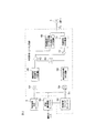
図1の装置は、我々の先のEP−A−0612641の装置と同一であり、かつ図示したシステムを十分に説明するために、その先行技術書類をここで参照する。EPーAー0612641の全ての説明のうちそれらの部分のみを、図示したシステムの動作の基本的な理解にとって必要であるものとしてここに含める。
【0013】
図1に示されるクルーズコントロール装置は、内燃機関によって駆動される車両内に設けられ、前方車両を検出するため、前方に向けられ、車両前部に装着されたレーダーシステム1を備える。レーダーシステム1は、車両と前方車両との間の距離に対応する距離出力と、車両と前方車両との速度差に対応する相対速度出力Vrelとを供給する。
【0014】
レーダーシステム1の距離出力は、減算器3の加算入力に供給される。減算器3の減算入力は、所望距離設定回路4の出力に接続され、その入力は車両の速度を決定するための車両速度センサ5に接続される。センサ5は、適当なあらゆるセンサ、たとえば地上光学速度センサ(an optical speed over ground sensor) や車輪速度の測定に基づいて車両速度を決定するためのシステムを含んでいてもよい。
【0015】
減算器3の出力は、乗算器6の第1入力に供給され、その第2入力は、入力がレーダーシステム1の距離出力に接続される距離利得設定回路2の出力に接続される。乗算器6の出力は、加算器7の第1入力に接続され、その第2入力は、相対速度信号を受けるために乗算器28を介してレーダーシステム1に接続される。乗算器28は、加算器7による使用に先立って、相対速度信号をスケーリングするようになっている。乗算器28は、1の利得が相対速度信号に与えられるなら、省略されてもよい。加算器7の出力は、加速度要求信号の最大正負値を制限するためのリミッタ10の入力に接続される。例えば、最大正加速度は、15%gもしくはそれ以下になるように制限されてもよく、かつ最大減速度は、30%gもしくはそれ以下になるように制限されてもよく、ここでgは重力による加速度である。リミッタ10からの制限された加速度要求信号は、減算器8の加算入力に供給され、その減算入力は、微分器9の出力に接続される。微分器9の入力は、車両速度センサ5に接続され、そのため微分器9は、車両加速度に対応する信号を与える。
【0016】
減算器8の出力は、加速度誤差信号を表し、電子スイッチ11および12を含むゲート配列に供給される。スイッチ11は、減算器8の出力を乗算器13の第1入力に選択的に接続し、その第2入力は積分利得設定回路14の出力に接続される。回路14の入力は、車両速度センサ5の出力に接続される。スイッチ11は、リミッタ10の出力に接続される第1入力と、通常ゼロを越える加速度誤差に対応する第1しきい値T1を受けるように接続される第2入力とを有する比較器15によって制御される。乗算器13の出力は、車両の内燃機関のスロットルアクチュエータ16の入力に接続される。スロットルアクチュエータ16は、供給される信号の時間に関する積分に従って、エンジンスロットルを制御するタイプのものである。
【0017】
スイッチ12は、減算器8の出力を、車両のブレーキアクチュエータ17に選択的に接続する。スイッチ12は、3つの入力を有するANDゲート18の出力に接続される制御入力を有する。第1入力は、リミッタ10の出力に接続される第1入力と、ゼロ未満の加速度に対応するしきい値T2を受けるように接続される第2入力とを有する比較器19の出力に接続される。ゲート18の第2入力は、相対速度信号を受けるようにレーダーシステム1に接続される第1入力と、ゼロ未満である相対速度または速度誤差に対応するしきい値T3を受けるように接続される第2入力とを有する比較器20に接続される。ゲート18の第3入力は、距離誤差信号を受けるように減算器3の出力に接続される第1入力と、ゼロ未満の距離誤差に対応するしきい値T4を受けるように接続される第2入力とを有する比較器21の出力に接続される。
【0018】
リミッタ10は、リミッタが加速度要求信号を所定の最大限界値まで制限するのを防ぐためのディザーブル入力(disabling input) を有する。ディザーブル入力は、2つの入力を有するANDゲート22の出力に接続される。ゲート22の第1入力は、加算器7の出力に接続される第1入力と、リミッタの最大または上限値に等しい加速度要求に対応するしきい値T5を受ける第2入力とを有する比較器23の出力に接続される。ゲート22の第2入力は、微分器9の出力に接続される第1入力と、ゼロと上限値との間の加速度に対応するしきい値T6を受ける第2入力とを有する比較器24の出力に接続される。
【0019】
距離利得設定回路2は、2つの入力を有するANDゲート25の出力に接続される入力を有する。ゲート25の第1入力は、減算器3の出力に接続される第1入力と、ゼロを越える所定の距離誤差に対応するしきい値T7を受ける第2入力とを有する比較器26の出力に接続される。ゲート25の第2入力は、レーダーシステム1からの相対速度信号を受けるように接続される第1入力と、ゼロを越える所定の速度誤差に対応するしきい値T8を受ける第2入力とを有する比較器27の出力に接続される。
【0020】
クルーズコントロールが選択されると、図1に示されるクルーズコントロール装置は、例えば運転者がクルーズコントロールをオフに切り換えるかまたは車両の加速装置またはブレーキ制御装置を作動することによって、クルーズコントロールがディザーブルされない限りかつディザーブルされるまで、自動的にエンジンスロットルおよび車両ブレーキシステムを制御する。レーダーシステム1は、車両とその前方の最も接近した他の車両との間の距離と、その2台の車両間の速度差とにそれぞれ対応する距離および相対速度信号を供給する。距離は、減算器3に供給される。減算器3は、回路4によって発生される所望距離から実際の距離を引くことによって、距離誤差信号を形成する。回路4は、所望距離を、センサ5によって測定される車両速度の関数として設定する。回路4は、リードオンリメモリ(ROM)に記憶されるルックアップテーブルまたは車両速度に基づく関数値を算定するための算定回路を備えてもよい。例えば、所望距離Sが、以下の式に従って決定されてもよい:
S=(0.23×V)+7
ここで所望距離Sは、メートルで与えられ、かつVはkphでの車両速度である。
【0021】
定数7メートルがない時には、車両は、0.83秒の時間間隔で前方の車両を追従するように配置されるであろう。しかしながら、柔軟性を増すために、所望距離設定回路4は、例えば0.8および2.5秒の所定の限界内の所望距離を選択するために、運転者によって制御可能であってもよい。定数7メートルは、比較的低速度については、車両が前方車両からの最小間隔を維持することを保証し、そのため例えば、もし前方車両が止まれば、クルーズコントロール下の車両は衝突を防ぐのに十分な所望距離をもって止まるだろう。
【0022】
減算器3からの距離誤差は、乗算器6において、距離利得回路2に設定されている距離利得と乗算される。回路2は、リードオンリメモリに記憶されるルックアップテーブル、または主として2台の車両間の実際の距離の関数として距離利得を算定する手段を備えてもよい。距離利得は、例えば、6メートル以下の目標距離について最大値7、および20メートルを越える目標距離について最小値1を有してもよい。6メートルと20メートルとの間では、距離利得は、単調かつ連続的に、または実質的に連続的に減少する。
【0023】
乗算器6の出力は、加算器7によって速度誤差信号に加えられる。すなわち、この実施例では、乗算器28は1の利得を有する。このように20メートル以上の目標距離では、1の比較的低い距離利得が距離誤差に与えられ、それゆえに速度誤差はクルーズコントロールに対し、より多くの影響を及ぼす。比較的低い距離利得についてでも、距離誤差がかなりの時間存続するなら、スロットルアクチュエータ16の積分作用により距離誤差は円滑に修正される。
【0024】
比較的小さい所望距離では、距離誤差に対する迅速な応答が必要であり、距離利得は、20メートル未満の目標距離については、6メートル以下の目標距離に対応する最大値7に達するまで、漸進的に増加する。そのような小さい所望距離では、いかなる距離誤差も所望距離の比較的大きな割合を表し、距離誤差を排除して、例えば車両が前方車両にあまりにも接近しすぎるのを防ぐための迅速な応答が必要である。よって、比較的小さい所望距離では、距離誤差は、車両制御において、速度誤差より実質的に大きな影響を及ぼす。
【0025】
ゲート25の出力が活性(active)である時、信号は回路2の第2入力に供給され、そのため回路は機能に従って設定された距離利得を半分にする。比較器26は、距離誤差が比較的大きい、すなわちクルーズコントロール下の車両が前方車両から比較的後方にいる時を検出する。比較器27は、クルーズコントロール下の車両が前方車両に近づきつつあるというような速度誤差である時はいつかを決定する。このように、制御車両は近づきつつあるが、前方車両から比較的後方にある時、距離利得は、オーバシュートを防ぐために半分にされる。
【0026】
ゲート18、スイッチ11および12、ならびに比較器15および比較器19を含むゲート配置は、正の加速度要求がエンジンスロットルを制御し、負の加速度要求が車両ブレーキを制御することを保証する。しきい値T1およびT2は、実質的にゼロに等しくされてもよいし、スロットル制御とブレーキ制御との間の「デッドバンド(dead band)」を提供するために、それぞれ所定の正の値および負の値にされてもよい。
【0027】
加算器7の出力は、加速度要求信号を表し、その信号自体は、適当に処理されかつ例えばスロットルアクチュエータ16およびブレーキアクチュエータ17に与えられることによって、車両の加速度を制御するために用いられ得る。しかしながら、加速度の閉ループ制御のために、加速度要求は、減算器8において実際の車両加速度と比較され、加速度誤差を形成する。加算器7からの加速度要求は、リミッタ10によって+15%gの最大値および−30%gの最小値まで制限される。加速度および減速度のこれらの最大値は、車両の乗客の快適さに都合がよいように求められている。
【0028】
我々の先のEP−A−0612641の公知のシステムでは、前方の目標車両までの「所望距離」は、所望距離設定手段4によって、車両速度またはルックアップテーブルを用いる算定によって設定される。しかしながら、より精巧な変型では、所望距離は、(秒での)所望運転間隔の点から運転者によって予め選択され得る。このように、運転者は、例えば1.5秒、2秒、2.5秒等、目標車両との間隔を保ちたいと望むかどうかを選択できる。所望運転間隔の変動性は、所望距離設定回路4へ入力されるダッシュ線によって図1に示される。
【0029】
通常のクルーズコントロールモードでは、最小動作速度は、通常、時速40Km(40kph)の特定の値に設定されてもよく、この最小速度により、先行(目標)車両からの所望距離を、秒による所望運転間隔および制御車両の現在速度を用いてシステムによって算定することができる。
しかしながら、車両速度が40kpm未満に速度を落とし、かつ零へ向かうにつれて、先行車両との間に距離間隔を確立するための運転時間間隔は無限大へ向かい、そのために先行車両までの意味のある所望距離(静止での)を、所望運転間隔(秒)×制御車両速度(m/s)に基づいて算定することができない。
【0030】
制御車両速度が零になる時、制御車両と先行(目標)車両との間に残余距離があるべきである。この静止での残余距離は、運転者が選択した運転間隔に関連すべきである。例えば、1.5秒の所望運転間隔が、静止での5メートルの所望距離となるとすれば、2秒の運転間隔は、やや長い静止での所望距離となるべきである。
【0031】
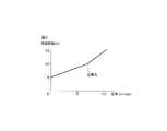
このように、制御車両と先行車両との間隔を所望運転間隔(スピードを出しているとき)に基づかせる状態と、残余所望距離(静止での)に基づかせる状態との間で遷移がある必要がある(図3参照)。
この発明は、クルーズコントロール車両の速度が減少するにつれて、その所望距離が、より速い速度の場合の所望距離(運転間隔所望距離。HD距離)からより遅い速度の場合の所望距離(残余所望距離。RD距離)へ遷移するように、所望距離の算定を、運転間隔所望距離が減少するにつれて、(秒での)運転間隔を(メートルでの)残余距離に混ぜるように行う手段を提供する。運転間隔所望距離は、所望運転間隔( sec )に車両速度 (m/s) を乗じて得られるので、車両速度の減少に伴って減少する。
【0032】
これは、ここで参照される図2に模式的に示される配置を用いる好ましい実施例で達成される。
運転者は、車両が通常のクルーズコントロール下にある時、すなわち40kphを越える速度で動作しているとき、システムによって採用されるべき所望運転間隔を選択することができる。この所望運転間隔は、所望運転間隔エレメント50へ手動で入力され、このエレメント50は、所望運転間隔を表す信号を残余距離ファクタエレメント52に供給し、エレメント52は、その出力ライン54上で、所望運転間隔に応じて増加する残余距離ファクタを設定する。しかしながら、その距離ファクタが所望運転間隔と共に増加する割合は、所望運転間隔が増加するにつれて減少する。
【0033】
運転者が選択したエレメント50からの所望運転間隔と、エレメント52からの残余距離ファクタは、乗算器56で乗算され、エレメント58の残余所望距離を形成する。乗算器60において、残余所望距離の値に所定の係数(この例では2)が掛けられ、かつその結果が比較器62の一方入力に与えられる。運転者が選択したエレメント50からの所望運転間隔は、さらなる乗算器64(運転間隔所望距離演算手段)において、車両速度センサ5から得られる制御(AICC)車両速度と乗算され、エレメント66の運転間隔所望距離を形成する。結果として生じる運転間隔所望距離値が、比較器62の第2入力に与えられる。比較器62は、その第2入力での信号がその第1入力での信号未満である場合に、すなわち(この実施例で)所望運転間隔距離が残余所望距離の2倍未満である時、高レベル出力(第2出力信号)を与える。高レベル出力が比較器62上にある場合に、エレメント68が作動され、次の式に等しい所望距離を、ライン70上で出力する。
{2×残余所望距離−運転間隔所望距離/2}+運転間隔所望距離
一方、もし比較器62の出力が低レベル(第1出力信号)であるなら、インバータ72は、エレメント74を作動するために、高レベル出力を与え、運転間隔所望距離に等しい所望距離を、ライン70上で出力する。
【0034】
以上を以下に要約すると:
運転間隔所望距離(HD距離)(m)
=所望運転間隔(sec)×車両速度(m/s)
残余所望距離(RD距離)(m)
=所望運転間隔(sec)×残余距離ファクタ
もし:HD距離<2×RD距離ならば、
所望距離={2×RD距離−HD距離/2}+HD距離
さもなければ:所望距離=HD距離
すなわち、所望距離設定回路4は、HD距離≧2×RD距離ならば、
所望距離=HD距離
によって「所望距離」を算定する第1状態となり、HD距離<2×RD距離ならば、
所望距離={2×RD距離−HD距離/2}+HD距離
によって「所望距離」を算定する第2状態となる。車両速度の減少に伴ってHD距離は小 さくなるので、減速時には、所望距離設定回路4は、上記第1状態から上記第2状態へと遷移する。HD距離は、車両速度に依存するので、上記第2状態における「所望距離」は、結局、「残余所望距離」を車両速度に依存する割合で含むことになる。第1状態から第2状態への切り換えは、比較器62の出力により行われる。
このように、この発明による上述の実施例では、図1の公知のシステムにおいて、所望距離設定回路4によって減算器3に与えられる所望距離の代わりに、図2のライン70上に設定される所望距離の値が用いられる。
【0035】
上述の実施例で用いられた所望距離、残余所望距離および運転間隔所望距離の間の関係は、例としてのみ与えられており、他の関係もまた、上述の原理と矛盾することなく等しく適用され得る。同様に、切り換えが生じる点(HD距離<(2×RD距離))は、ここで説明した動作原理内で動作しつつ変動しうる。
【0036】
【発明の効果】
この発明によると、制御車両と先行(目標)車両との間の所望の時間間隔として与えられる運転者の所望運転間隔要求に従って動作するAICCクルーズコントロールシステムが提供され、目標車両が零速度へ向かって減速すると、当該制御車両から前記目標車両までの所望距離を純粋に前記所望運転間隔に基づく運転間隔所望距離として算定する状態から、静止での残余所望距離を前記制御車両の速度に依存する割合で含むように前記所望距離を算定する状態へと遷移する。
【0037】
このことは、車両と目標との間の適応可能な位置の間隔が静止で維持され、かつその間隔は運転者の運転間隔要求に依存するということを保証する。すなわち、もし運転者が大きな時間間隔を求める(大きな運転間隔要求)なら、停止時における制御車両と目標との間隔(残余所望距離)は、より小さな時間間隔を運転者が求める場合の残余所望距離よりも大きくなる。
【図面の簡単な説明】
【図1】この発明が適用可能な公知のクルーズコントロール装置の一実施例のブロック回路図である。
【図2】この発明による、修正された所望距離形成装置の一実施例を示すブロック図である。
【図3】この発明の装置で利用される切り換え位置を示すグラフである。
【符号の説明】
1 レーダーシステム
2 距離利得回路
3,8 減算器
4 所望距離設定回路
5 車両速度センサ
6,28,13,28,56,60,64 乗算器
7 加算器
9 微分器
10 リミッタ
11,12 電子スイッチ
14 積分利得設定回路
15,19,20,21,23,24,26,27,62 比較器
16 スロットルアクチュエータ
17 ブレーキアクチュエータ
18,22,25 ANDゲート
50 所望運転間隔エレメント
52 残余距離ファクタエレメント
54 出力ライン
58,66,68,74 エレメント
70 ライン
72 インバータ[0001]
BACKGROUND OF THE INVENTION
The present invention relates to a cruise control system for a vehicle.
[0002]
[Prior art]
It is well known to provide a cruise control equipment of the vehicle, because of its equipment, while the driver can set the target vehicle speed, cruise control Ru Tei is operated, the target actual vehicle speed to maintain the speed, the car both velocity is adjusted automatically by the cruise controller. Such known controllers do not monitor the distance or speed between the control vehicle and the vehicle in front of it, so if the vehicle under cruise control is too close to the vehicle in front, for example between vehicles In order to ensure that a “safe” braking distance remains, the driver must intervene based on factors such as road conditions, weather conditions and vehicle performance as perceived by the driver. For driver intervention, for example by applying the foot brake of the vehicle or by moving the cruise control lever to the off position, the set target speed is adjusted to the new target, or the entire cruise control is at least temporarily Switching off may be included. When the preceding vehicle increases its speed, the vehicle driver under cruise control can also easily operate the cruise control operating lever to manually increase the target speed to meet the new target.
[0003]
Recent developments in cruise control include making the cruise control system aware of and reacting to the presence and movement of a vehicle traveling in front of a vehicle under cruise control ( hereinafter referred to as the “ target vehicle ” ) , Includes reducing the need for driver intervention. This type of system is referred to as having Autonomous Intelligent Cruise Control (AICC), but is disclosed in EP-A-0612641 referred to herein, where the cruise control device is a desired between the target vehicle and the control vehicle. distance and the distance error determining means for determining a distance error as the difference between the distance of the actual, and speed error determining means for determining a speed error as the difference between the speed of the speed and control the vehicle target vehicle, the distance error and the speed of Acceleration request generating means for generating a vehicle acceleration request as a function of the error.
[0004]
Acceleration request, a distance error and a first gain parameter product, can be calculated as the sum of the speed error and a second gain parameter of the product. The second gain parameter may be a constant such as 1.
Distance and speed errors can be determined in many ways, for example using an electromagnetic or ultrasonic radar system that directly measures the distance to the target vehicle ahead. The speed error can be obtained by differentiating the radar system output with respect to time. As another system, the speed error may be automatically formed by the radar system, for example if the radar system is a Doppler type.
[0005]
A preferred embodiment of the known system shown in EP-A-0612641 also includes a desired distance determining means for determining the desired distance as a function of the vehicle speed, for example a linear function. It preferably also includes acceleration error generating means for generating an acceleration error as the difference between the calculated acceleration request and the actual vehicle acceleration.
The device of EP-A-0612641 also provides an acceleration error to the vehicle drive system when the acceleration demand exceeds a first threshold (≧ 0) and the acceleration demand is below a second threshold, and the distance Gating means for supplying an acceleration error to the vehicle braking system when the error is less than a second predetermined distance error (<0) and the speed error is less than a second predetermined speed error (<0).
[0006]
Therefore, the cruise control system of the type disclosed in our EP-A-0612641 refers to the relative speed and relative distance of the target vehicle traveling in front of the control vehicle on the road, and determines the travel speed of the control vehicle. Can be determined. If the target vehicle increases its speed, the speed of the control vehicle will correspondingly increase to the current target speed that the driver has initialized. Similarly, if the target vehicle slows down, the control vehicle is also decelerated by reducing the throttle or by applying vehicle braking with the throttle reduced. If the target vehicle stops, the control vehicle will also stop a predetermined distance behind the target vehicle.
[0007]
[Problems to be solved by the invention]
In this regard, there arises a problem of how to establish a predetermined driving interval (distance) for the rear vehicle. The control vehicle should stop a predetermined distance behind the target vehicle stopped in front. If the predetermined distance, if determined result by multiplying the speed of the controlled vehicle in time OPERATION has set interval, established as the speed of the vehicle under cruise control is directed to zero, the distance interval between the target vehicle in order to will suited operation interval of time units to infinity. Therefore , a meaningful desired distance to the target vehicle cannot be calculated based on the driving interval in time units. As a result, it is difficult to establish a method for skillfully decelerating or stopping the control vehicle in relation to the target vehicle.
[0008]
The object of the present invention is to establish a solution to this problem.
[0009]
[Means for Solving the Problems]
In accordance with the present invention, an AICC cruise control system is provided that operates in accordance with a driver's desired driving interval requirement given as a desired time interval between a control vehicle and a preceding (target) vehicle so that the target vehicle moves toward zero speed. When the vehicle decelerates, the remaining desired distance at rest is a ratio that depends on the speed of the control vehicle from a state in which the desired distance from the control vehicle to the target vehicle is purely calculated as the operation interval desired distance based on the desired operation interval. It said desired distance so as to include the device transits to the state to calculate the.
[0010]
This ensures that the adaptable position distance between the vehicle and the target is kept stationary and that the distance depends on the driver's driving distance requirements. That, and if the driver obtains a larger time interval (greater headway request), the interval between the controlled vehicle and the target at the time of stop (residual desired distance), yo Ri residual desired if a small time interval the driver asks larger than the distance Kunar.
[0011]
In a preferred embodiment, the desired distance calculation constant in a pure time-based interval, switching to calculate the desired distance in a proportion which depends the desired residual distance at rest rate of the controlled vehicle, the control vehicle speed and the desired headway Ru done with the speed decreasing operation between 隔所 Nozomu distance obtained by multiplying a.
In a preferred operating method to achieve this effect, the desired distance that the system defined as the target, as long as the operation between 隔所 Nozomu distance is not substantially less than twice the residual desired range, headway desired distance (driver selects ( The desired driving interval in time unit × corresponding to the control vehicle speed), and when the desired driving interval is less than twice the remaining desired distance, the desired distance determined by the system as a target Is the following formula:
Desired distance = {2 × desired desired distance − running interval desired distance / 2} + running interval desired distance .
[0012]
DESCRIPTION OF THE PREFERRED EMBODIMENT
The invention will now be further described, by way of example only, with reference to the accompanying drawings.
The apparatus of FIG. 1 is identical to our previous EP-A-0612641 apparatus and reference is made here to its prior art document to fully describe the illustrated system. Only those portions of all the descriptions of EP-A-0612641 are included here as necessary for a basic understanding of the operation of the illustrated system.
[0013]
The cruise control device shown in FIG. 1 is provided in a vehicle driven by an internal combustion engine, and includes a radar system 1 that is directed forward and mounted on the front of the vehicle in order to detect a forward vehicle. The radar system 1 supplies a distance output corresponding to the distance between the vehicle and the preceding vehicle and a relative speed output Vrel corresponding to the speed difference between the vehicle and the preceding vehicle.
[0014]
The distance output of the radar system 1 is supplied to the addition input of the subtracter 3. The subtraction input of the subtracter 3 is connected to the output of the desired
[0015]
The output of the subtracter 3 is supplied to the first input of the multiplier 6, and the second input is connected to the output of the distance
[0016]
The output of the subtractor 8 represents an acceleration error signal and is supplied to a gate array including
[0017]
The
[0018]
The
[0019]
The distance
[0020]
When cruise control is selected, the cruise control device shown in FIG. 1 will not be disabled unless cruise control is disabled, for example, by the driver switching cruise control off or activating the vehicle's accelerator or brake control device. And automatically controls the engine throttle and vehicle brake system until disabled. Radar system 1 supplies the distance between the vehicle and the closest to the other vehicle of the front, the corresponding distance and the relative speed signal to the speed difference between the two vehicles. The distance is supplied to the subtracter 3. Subtractor 3, by subtracting the actual distance from the desired distance generated by the
S = (0.23 × V) +7
Where the desired distance S is given in meters and V is the vehicle speed in kph.
[0021]
In the absence of a constant 7 meters, the vehicle will be positioned to follow the vehicle ahead in a time interval of 0.83 seconds. However, to increase flexibility, desired
[0022]
Distance error from the subtracter 3, the multiplier 6, is multiplied by the distance gain in
[0023]
The output of the multiplier 6, Ru added to the speed error signal by the adder 7. That is, in this embodiment,
[0024]
In a relatively small desired distance, rapid response to distance error is required, the distance gain for target distances less than 20 meters until it reaches the maximum value 7 for the following target distance 6 meters, gradually proceeds Increase. In such small desired distance, any distance error also represents a relatively large proportion of the desired distance, with the exclusion of distance error, for example, the vehicle needs a rapid response to prevent too close too the front of the vehicle It is. Thus, at a relatively small desired distance , the distance error has a substantially greater effect on the vehicle control than the speed error.
[0025]
When the output of
[0026]
Gate 1 8, the gate arrangement comprising a
[0027]
The output of the adder 7 represents an acceleration request signal, which signal itself can be used to control the acceleration of the vehicle by being appropriately processed and applied to, for example, the
[0028]
In the known system of our previous EP-A-0612641, the “desired distance ” to the target vehicle ahead is set by the desired distance setting means 4 by calculation using a vehicle speed or a look-up table. However, in more sophisticated variants, the desired distance can be preselected by the driver in terms of the desired driving interval (in seconds). In this way, the driver can select whether he / she wants to keep the distance from the target vehicle, for example, 1.5 seconds, 2 seconds, 2.5 seconds or the like. The variability of the desired operation interval is shown in FIG. 1 by a dash line input to the desired
[0029]
In normal cruise control mode, the minimum operating speed may usually be set to a specific value of speed 40 Km (40Kph), this minimum speed, the desired distance from the preceding (target) vehicle, desired driving in seconds It can be calculated by the system using the distance and the current speed of the control vehicle.
However, as vehicle speed slows down below 40Kpm, and toward zero, OPERATION time interval for establishing the distance interval between the preceding vehicle is directed to infinity, meaningful to the preceding vehicle for the The desired distance (at rest) cannot be calculated based on the desired driving interval (seconds) x controlled vehicle speed (m / s).
[0030]
When the control vehicle speed reaches zero, there should be a residual distance between the control vehicle and the preceding (target) vehicle. This remaining distance at rest should be related to the driving interval selected by the driver. For example, the desired headway of 1.5 seconds, if a desired
[0031]
Thus, need to have a transition between a state in which based on intervals of the desired operating interval between the controlled vehicle and the preceding vehicle (when speeding), a state in which based on the residual desired distance (in the still) (See FIG. 3).
The present invention, as the speed of the cruise control vehicle is reduced, the desired distance, the desired distance when more have fast speed (headway desired distance. HD distance) desired distance when the slower rate (residual desired distance. as transition to RD distance), to calculate the desired distance, as oPERATION interval desired distance decreases, (in seconds) the operation interval (in meters) remaining distance to means for performing such mixing Zell Provide . The desired driving interval is obtained by multiplying the desired driving interval ( sec ) by the vehicle speed (m / s), and therefore decreases as the vehicle speed decreases.
[0032]
This is achieved in a preferred embodiment using the arrangement shown schematically in FIG. 2 referenced herein.
The driver can select the desired driving interval to be employed by the system when the vehicle is under normal cruise control, i.e. operating at a speed exceeding 40 kph. This desired operating interval is manually input to the desired
[0033]
The desired driving interval from
{2 × residual desired distance - OPERATION interval desired distance / 2} + headway desired distance Meanwhile, if the output of the
[0034]
To summarize the above:
Driving distance desired distance (HD distance ) (m)
= Desired driving interval (sec) x vehicle speed (m / s)
Desired remaining distance (RD distance ) (m)
= Desired driving interval (sec) x residual distance factor If: HD distance <2 x RD distance ,
Desired distance = {2 × RD distance -H D distance / 2} + HD Distance otherwise: the desired distance = HD distance
That is, the desired
Desired distance = HD distance
Is the first state for calculating the “desired distance”, and if HD distance <2 × RD distance,
Desired distance = {2 × RD distance−HD distance / 2} + HD distance
To enter the second state in which the “desired distance” is calculated. Since HD distance is small fence with decreasing vehicle speed, the deceleration is desired
Thus, in the above-described embodiment according to the invention, in the known system of FIG. 1, the desired distance set on line 70 of FIG. 2 instead of the desired distance given to the subtractor 3 by the desired
[0035]
Desired distance used in the above embodiment, the relationship between the residual desired distance and headway desired distance is given only as examples, other relationships may also be equally applied Consistent with the principles discussed above obtain. Similarly, the point at which switching occurs (HD distance <(2 × RD distance )) can vary while operating within the operating principles described herein.
[0036]
【The invention's effect】
In accordance with the present invention, an AICC cruise control system is provided that operates in accordance with a driver's desired driving interval requirement given as a desired time interval between a control vehicle and a preceding (target) vehicle so that the target vehicle moves toward zero speed. When decelerating, at a rate which depends from state to calculate purely as the desired operation based on distance headway desired distance desired distance from the controlled vehicle to the target vehicle, the remaining desired distance in the stationary speed of the controlled vehicle It said desired distance so as to include the device transits to the state to calculate the.
[0037]
This ensures that the adaptable position distance between the vehicle and the target is kept stationary and that the distance depends on the driver's driving distance requirements. That, and if the driver obtains a larger time interval (greater headway request), the interval between the controlled vehicle and the target at the time of stop (residual desired distance), yo Ri residual desired if a small time interval the driver asks larger than the distance Kunar.
[Brief description of the drawings]
FIG. 1 is a block circuit diagram of an embodiment of a known cruise control device to which the present invention is applicable.
FIG. 2 is a block diagram showing an embodiment of a modified desired distance forming apparatus according to the present invention.
FIG. 3 is a graph showing a switching position used in the apparatus of the present invention.
[Explanation of symbols]
1
Claims (7)
目標車両が零速度へ向かって減速すると、当該制御車両から前記目標車両までの所望距離を純粋に前記所望運転間隔に基づく運転間隔所望距離として算定する第1状態から、静止での残余所望距離を前記制御車両の速度に依存する割合で含むように前記所望距離を算定する第2状態へと遷移する所望距離設定手段を含むことを特徴とするクルーズコントロールシステム。A cruise control system of the type that operates according to a driver's desired driving interval requirement given as a desired time interval between a control vehicle and a preceding target vehicle,
When the target vehicle decelerates toward zero speed , the remaining desired distance at rest is calculated from the first state in which the desired distance from the control vehicle to the target vehicle is calculated purely as the driving interval desired distance based on the desired driving interval. cruise control system which comprises a desired distance setting means for transition to the second state to calculate the desired distance as a proportion which depends on the speed of the controlled vehicle.
前記所望距離設定手段は、
前記所望運転間隔と前記制御車両の速度とを乗じることによって前記運転間隔所望距離を演算する運転間隔所望距離演算手段と、
この運転間隔所望距離演算手段によって演算される運転間隔所望距離の減少に伴って、前記第1状態から前記第2状態へと切り換える切り換え手段とを含む、クルーズコントロールシステム。The cruise control system according to claim 1,
The desired distance setting means includes
Driving interval desired distance calculating means for calculating the driving interval desired distance by multiplying the desired driving interval and the speed of the control vehicle;
A cruise control system comprising switching means for switching from the first state to the second state as the desired driving distance is calculated by the desired driving distance calculation means .
前記切り換え手段は、前記運転間隔所望距離演算手段によって演算される運転間隔所望距離が残余所望距離のほぼ2倍未満にならない限り、前記第1状態を選択し、前記運転間隔所望距離が前記残余所望距離のほぼ2倍未満の場合に前記第2状態を選択するものであり、
前記所望距離設定手段は、前記第2状態での所望距離を、次式(A):
所望距離={2×残余所望距離−運転間隔所望距離/2}+運転間隔所望距離
……(A)
により算定するものである、クルーズコントロールシステム。The cruise control system according to claim 2 ,
Said switching means, said unless headway desired distance is calculated by the headway desired distance calculating means does not become less than approximately two times the residual desired range, the first state is selected, the operation interval desired distance the residual desired The second state is selected when the distance is less than twice the distance ;
The desired distance setting means calculates the desired distance in the second state by the following formula (A) :
Desired distance = {2 × desired desired distance − operating interval desired distance / 2} + desired operating interval
...... (A)
Cruise control system that is calculated by
前記切り換え手段は、係数2を掛けられた残余所望距離を、前記運転間隔所望距離演算手段によって演算される運転間隔所望距離と比較し、運転間隔所望距離が残余所望距離の2倍未満であるという条件が満たされない場合には第1出力信号を出力し、この条件が満たされる場合には第2出力信号を出力する比較手段(62)を含む、クルーズコントロールシステム。The cruise control system according to claim 3 ,
That said switching means, a residual desired distance which is multiplied by a factor 2, compared with the headway desired range, which is calculated by the headway desired distance calculating means, headway desired distance is less than twice the residual desired distance If the condition is not satisfied and outputs a first output signal, if this condition is Ru satisfied comprises a specific 較手 stage (62) for outputting a second output signal, the cruise control system.
前記所望距離設定手段は、前記比較手段が前記第2出力信号を出力すれば、前記式(A)の所望距離を算定するものである、クルーズコントロールシステム。The cruise control system according to claim 4 ,
It said desired distance setting means, the comparing means lever to output the second output signal, Ru der those to calculate the desired distance of the formula (A), a cruise control system.
運転者が所望運転間隔値を手動で入力することのできる所望運転間隔手段(50)を含み、この所望運転間隔手段は、残余距離ファクタを設定する残余距離ファクタ手段(52)へ所望運転間隔を表す信号を供給し、前記残余距離ファクタ手段(52)は、所望運転間隔に応じて増加する残余距離ファクタを設定し、残余距離ファクタが所望運転間隔と共に増加する割合は、所望運転間隔が増加するにつれて減少する、クルーズコントロールシステム。The cruise control system according to claim 1, 2 , 3, 4 or 5 ,
The driver comprises a desired headway means (50) which can be manually enter the desired headway value, the desired headway means, the desired headway to the rest distance factor means (52) for setting a residual distance factor a signal representative of is supplied, the remaining distance factor means (52) sets a residual distance factor increases with Nozomu Tokoro headway, the proportion of the residual distance factor increases with desired headway is desired headway increases decreasing, cruise control system as you.
前記所望運転間隔手段(50)からの運転者が選択した所望運転間隔と、前記残余距離ファクタ手段(52)からの残余距離ファクタとを乗算し、残余所望距離を生成する乗算器(56)をさらに含む、クルーズコントロールシステム。The cruise control system according to claim 6 ,
A desired headway driver from said desired headway means (50) is selected, the multiplying the remaining distance factor from the residual distance factor means (52), a multiplier for generating a residual desired distance (56) In addition , a cruise control system.
Applications Claiming Priority (2)
| Application Number | Priority Date | Filing Date | Title |
|---|---|---|---|
| GB9425057:8 | 1994-12-13 | ||
| GBGB9425057.8A GB9425057D0 (en) | 1994-12-13 | 1994-12-13 | Apparatus and method for cruise control |
Publications (2)
| Publication Number | Publication Date |
|---|---|
| JPH08230514A JPH08230514A (en) | 1996-09-10 |
| JP3860239B2 true JP3860239B2 (en) | 2006-12-20 |
Family
ID=10765811
Family Applications (1)
| Application Number | Title | Priority Date | Filing Date |
|---|---|---|---|
| JP34591795A Expired - Fee Related JP3860239B2 (en) | 1994-12-13 | 1995-12-08 | Cruise control system |
Country Status (5)
| Country | Link |
|---|---|
| US (1) | US5749426A (en) |
| EP (1) | EP0720928B1 (en) |
| JP (1) | JP3860239B2 (en) |
| DE (1) | DE69501663T2 (en) |
| GB (1) | GB9425057D0 (en) |
Cited By (1)
| Publication number | Priority date | Publication date | Assignee | Title |
|---|---|---|---|---|
| US11485360B2 (en) * | 2020-04-03 | 2022-11-01 | Baidu Usa Llc | Dynamic speed limit adjustment system based on perception results |
Families Citing this family (35)
| Publication number | Priority date | Publication date | Assignee | Title |
|---|---|---|---|---|
| US5934399A (en) * | 1995-10-31 | 1999-08-10 | Honda Giken Kogyo Kabushiki Kaisha | Automatically driven motor vehicle |
| GB9606381D0 (en) * | 1996-03-26 | 1996-06-05 | Jaguar Cars | Cruise control systems for motor vehicles |
| JP3143063B2 (en) * | 1996-06-07 | 2001-03-07 | 株式会社日立製作所 | Travel control device for moving objects |
| DE19654769A1 (en) * | 1996-12-30 | 1998-07-02 | Teves Gmbh Alfred | Method and device for vehicle control or regulation |
| US6009368A (en) * | 1997-03-21 | 1999-12-28 | General Motors Corporation | Active vehicle deceleration in an adaptive cruise control system |
| JP3395575B2 (en) * | 1997-06-10 | 2003-04-14 | 日産自動車株式会社 | Vehicle follow-up control system |
| DE19736756A1 (en) * | 1997-08-23 | 1999-02-25 | Volkswagen Ag | Distance control method and device for a vehicle |
| US6418370B1 (en) * | 1998-08-04 | 2002-07-09 | Denso Corporation | Apparatus and method for controlling a target distance and a warning distance between traveling vehicles and a recording medium for storing the control method |
| US6233515B1 (en) * | 1998-12-07 | 2001-05-15 | Jaguar Car, Limited | Adaptive vehicle cruise control system and methodology |
| JP3627582B2 (en) * | 1999-07-30 | 2005-03-09 | 日産自動車株式会社 | Vehicle tracking control device |
| DE19958520A1 (en) * | 1999-12-04 | 2001-06-07 | Bosch Gmbh Robert | Speed controller for a motor vehicle |
| JP3651355B2 (en) * | 1999-12-16 | 2005-05-25 | トヨタ自動車株式会社 | Vehicle deceleration control device |
| US6275764B1 (en) * | 1999-12-22 | 2001-08-14 | Visteon Global Technologies, Inc. | Method and system for providing a headway function to an adaptive speed control activation switch |
| DE19962752B4 (en) * | 1999-12-23 | 2014-03-27 | Volkswagen Ag | Method and device for speed and distance control of a motor vehicle |
| DE10017662A1 (en) * | 2000-04-08 | 2001-10-11 | Bosch Gmbh Robert | Method and device for controlling the distance of a vehicle from a preceding vehicle |
| US6304808B1 (en) * | 2000-09-09 | 2001-10-16 | Kelsey-Hayes Company | Enhanced active brake control system functionality through system integration with adaptive cruise control |
| US20030076981A1 (en) * | 2001-10-18 | 2003-04-24 | Smith Gregory Hugh | Method for operating a pre-crash sensing system in a vehicle having a counter-measure system |
| US6622810B2 (en) * | 2001-11-05 | 2003-09-23 | General Motors Corporation | Adaptive cruise control system |
| US6819991B2 (en) | 2001-11-29 | 2004-11-16 | Ford Global Technologies, Llc | Vehicle sensing based pre-crash threat assessment system |
| US6775605B2 (en) | 2001-11-29 | 2004-08-10 | Ford Global Technologies, Llc | Remote sensing based pre-crash threat assessment system |
| US6708099B2 (en) * | 2002-01-17 | 2004-03-16 | Ford Global Technologies, Llc | Stop and go adaptive cruise control system |
| US7158870B2 (en) * | 2002-01-24 | 2007-01-02 | Ford Global Technologies, Llc | Post collision restraints control module |
| US6831572B2 (en) | 2002-01-29 | 2004-12-14 | Ford Global Technologies, Llc | Rear collision warning system |
| US6721659B2 (en) | 2002-02-01 | 2004-04-13 | Ford Global Technologies, Llc | Collision warning and safety countermeasure system |
| US6519519B1 (en) | 2002-02-01 | 2003-02-11 | Ford Global Technologies, Inc. | Passive countermeasure methods |
| US7009500B2 (en) | 2002-02-13 | 2006-03-07 | Ford Global Technologies, Llc | Method for operating a pre-crash sensing system in a vehicle having a countermeasure system using stereo cameras |
| US6498972B1 (en) | 2002-02-13 | 2002-12-24 | Ford Global Technologies, Inc. | Method for operating a pre-crash sensing system in a vehicle having a countermeasure system |
| US6882923B2 (en) * | 2002-10-17 | 2005-04-19 | Ford Global Technologies, Llc | Adaptive cruise control system using shared vehicle network data |
| DE10310720A1 (en) * | 2003-03-10 | 2004-09-23 | Robert Bosch Gmbh | Method and device for regulating the speed of a motor vehicle |
| US7457699B2 (en) * | 2004-01-21 | 2008-11-25 | Delphi Technologies, Inc. | Technique for detecting truck trailer for stop and go adaptive cruise control |
| DE102006060554A1 (en) * | 2006-12-21 | 2008-06-26 | Bayerische Motoren Werke Ag | Steering wheel for a motor vehicle and motor vehicle |
| JP5332993B2 (en) * | 2009-07-15 | 2013-11-06 | トヨタ自動車株式会社 | Travel plan generator |
| GB2508668A (en) * | 2012-12-10 | 2014-06-11 | Jaguar Land Rover Ltd | Adaptive cruise control (ACC) means for a host vehicle having regenerative and non-regenerative braking means |
| CN105425233B (en) * | 2015-12-08 | 2018-08-03 | 安徽酷哇机器人有限公司 | For mobile device ranging and follow the device and method of positioning |
| US10279808B2 (en) | 2017-05-17 | 2019-05-07 | Bendix Commercial Vehicle Systems Llc | Adaptive cruise control system with speed based mode |
Family Cites Families (6)
| Publication number | Priority date | Publication date | Assignee | Title |
|---|---|---|---|---|
| FR2071418A5 (en) * | 1969-12-29 | 1971-09-17 | Dessailly Rene | |
| DE4003205A1 (en) * | 1990-02-03 | 1991-08-08 | Roland Wenz | Safety indicator for vehicle - shows safe spacing to preceding vehicle at every speed and can be incorporated into speedometer |
| US5014200A (en) * | 1990-02-20 | 1991-05-07 | General Motors Corporation | Adaptive cruise system |
| US5173859A (en) * | 1990-11-05 | 1992-12-22 | General Motors Corporation | Automatic vehicle deceleration |
| JPH04201643A (en) * | 1990-11-30 | 1992-07-22 | Mitsubishi Automob Eng Co Ltd | Between-vehicle distance detecting alarm device |
| GB9303434D0 (en) | 1993-02-20 | 1993-04-07 | Lucas Ind Plc | Method of and apparatus for cruise control |
-
1994
- 1994-12-13 GB GBGB9425057.8A patent/GB9425057D0/en active Pending
-
1995
- 1995-12-05 EP EP95308786A patent/EP0720928B1/en not_active Expired - Lifetime
- 1995-12-05 DE DE69501663T patent/DE69501663T2/en not_active Expired - Lifetime
- 1995-12-08 JP JP34591795A patent/JP3860239B2/en not_active Expired - Fee Related
- 1995-12-12 US US08/571,302 patent/US5749426A/en not_active Expired - Lifetime
Cited By (1)
| Publication number | Priority date | Publication date | Assignee | Title |
|---|---|---|---|---|
| US11485360B2 (en) * | 2020-04-03 | 2022-11-01 | Baidu Usa Llc | Dynamic speed limit adjustment system based on perception results |
Also Published As
| Publication number | Publication date |
|---|---|
| DE69501663T2 (en) | 1998-06-18 |
| JPH08230514A (en) | 1996-09-10 |
| DE69501663D1 (en) | 1998-04-02 |
| EP0720928A2 (en) | 1996-07-10 |
| US5749426A (en) | 1998-05-12 |
| EP0720928B1 (en) | 1998-02-25 |
| EP0720928A3 (en) | 1997-03-12 |
| GB9425057D0 (en) | 1995-02-08 |
Similar Documents
| Publication | Publication Date | Title |
|---|---|---|
| JP3860239B2 (en) | Cruise control system | |
| US5495251A (en) | Method of and apparatus for cruise control | |
| US5761629A (en) | Method and apparatus for cruise control | |
| US5771481A (en) | Apparatus and method for cruise control | |
| JP3818687B2 (en) | Cruise control system | |
| JP3838048B2 (en) | Vehicle travel control device | |
| US6618000B2 (en) | Method and device for controlling the distance from a vehicle to a preceding vehicle | |
| US6134497A (en) | Vehicle running control apparatus and vehicle running control method | |
| JP3497520B2 (en) | Vehicle speed and inter-vehicle distance control method and apparatus for implementing vehicle speed and inter-vehicle distance control method | |
| JP4028618B2 (en) | Method and apparatus for controlling the speed of a vehicle | |
| JPH10109565A (en) | Vehicle traveling speed control method and device thereof | |
| KR101693847B1 (en) | Adaptive cruise control system and control method thereof | |
| JPH1076867A (en) | Automatic running gear | |
| US6772059B2 (en) | Method for adaptive distance and/or driving speed adjustment in a motor vehicle | |
| KR20210022679A (en) | Vehicle operating method and control device | |
| JP2006175941A (en) | Acceleration/deceleration controller | |
| KR20160013940A (en) | Inter-vehicle distance maintaining control device | |
| JPH0717295A (en) | Speed control device for vehicle | |
| JP3033354B2 (en) | Constant-speed traveling device with inter-vehicle distance adjustment function | |
| JPH05262164A (en) | Automatic traveling speed controller | |
| GB2295698A (en) | Cruise control system | |
| JPH11334554A (en) | Run controller for vehicle | |
| JP2715798B2 (en) | Brake control method | |
| JP3233108B2 (en) | Constant-speed traveling device with inter-vehicle distance adjustment function | |
| US20230271611A1 (en) | Vehicle control device |
Legal Events
| Date | Code | Title | Description |
|---|---|---|---|
| A131 | Notification of reasons for refusal |
Free format text: JAPANESE INTERMEDIATE CODE: A131 Effective date: 20051213 |
|
| A601 | Written request for extension of time |
Free format text: JAPANESE INTERMEDIATE CODE: A601 Effective date: 20060307 |
|
| A602 | Written permission of extension of time |
Free format text: JAPANESE INTERMEDIATE CODE: A602 Effective date: 20060310 |
|
| A521 | Request for written amendment filed |
Free format text: JAPANESE INTERMEDIATE CODE: A523 Effective date: 20060609 |
|
| TRDD | Decision of grant or rejection written | ||
| A01 | Written decision to grant a patent or to grant a registration (utility model) |
Free format text: JAPANESE INTERMEDIATE CODE: A01 Effective date: 20060822 |
|
| A61 | First payment of annual fees (during grant procedure) |
Free format text: JAPANESE INTERMEDIATE CODE: A61 Effective date: 20060921 |
|
| R150 | Certificate of patent or registration of utility model |
Free format text: JAPANESE INTERMEDIATE CODE: R150 |
|
| FPAY | Renewal fee payment (event date is renewal date of database) |
Free format text: PAYMENT UNTIL: 20100929 Year of fee payment: 4 |
|
| FPAY | Renewal fee payment (event date is renewal date of database) |
Free format text: PAYMENT UNTIL: 20110929 Year of fee payment: 5 |
|
| LAPS | Cancellation because of no payment of annual fees |