JP3858141B2 - Liquid-filled vibration isolator - Google Patents
Liquid-filled vibration isolator Download PDFInfo
- Publication number
- JP3858141B2 JP3858141B2 JP2000165976A JP2000165976A JP3858141B2 JP 3858141 B2 JP3858141 B2 JP 3858141B2 JP 2000165976 A JP2000165976 A JP 2000165976A JP 2000165976 A JP2000165976 A JP 2000165976A JP 3858141 B2 JP3858141 B2 JP 3858141B2
- Authority
- JP
- Japan
- Prior art keywords
- orifice
- liquid
- vibration
- cylindrical
- diaphragm
- Prior art date
- Legal status (The legal status is an assumption and is not a legal conclusion. Google has not performed a legal analysis and makes no representation as to the accuracy of the status listed.)
- Expired - Lifetime
Links
- 239000007788 liquid Substances 0.000 title claims description 68
- 238000005192 partition Methods 0.000 claims description 45
- 230000002093 peripheral effect Effects 0.000 claims description 23
- 229910052751 metal Inorganic materials 0.000 claims description 22
- 239000002184 metal Substances 0.000 claims description 22
- 239000012528 membrane Substances 0.000 claims description 9
- 238000013016 damping Methods 0.000 claims description 8
- 229910010293 ceramic material Inorganic materials 0.000 claims description 4
- 239000000463 material Substances 0.000 claims description 4
- 229920003002 synthetic resin Polymers 0.000 claims description 4
- 239000000057 synthetic resin Substances 0.000 claims description 4
- 239000012530 fluid Substances 0.000 claims description 2
- 230000000694 effects Effects 0.000 description 7
- 239000000956 alloy Substances 0.000 description 2
- 229910045601 alloy Inorganic materials 0.000 description 2
- 229910052782 aluminium Inorganic materials 0.000 description 2
- XAGFODPZIPBFFR-UHFFFAOYSA-N aluminium Chemical compound [Al] XAGFODPZIPBFFR-UHFFFAOYSA-N 0.000 description 2
- 238000000465 moulding Methods 0.000 description 2
- 230000002265 prevention Effects 0.000 description 2
- 239000000758 substrate Substances 0.000 description 2
- 238000004073 vulcanization Methods 0.000 description 2
- 229910000831 Steel Inorganic materials 0.000 description 1
- 238000010521 absorption reaction Methods 0.000 description 1
- 239000000853 adhesive Substances 0.000 description 1
- 230000001070 adhesive effect Effects 0.000 description 1
- 230000008878 coupling Effects 0.000 description 1
- 238000010168 coupling process Methods 0.000 description 1
- 238000005859 coupling reaction Methods 0.000 description 1
- 238000006073 displacement reaction Methods 0.000 description 1
- 230000001771 impaired effect Effects 0.000 description 1
- 238000009413 insulation Methods 0.000 description 1
- 238000002955 isolation Methods 0.000 description 1
- 238000004519 manufacturing process Methods 0.000 description 1
- 230000011514 reflex Effects 0.000 description 1
- 230000003014 reinforcing effect Effects 0.000 description 1
- 239000010959 steel Substances 0.000 description 1
Images


Classifications
-
- F—MECHANICAL ENGINEERING; LIGHTING; HEATING; WEAPONS; BLASTING
- F16—ENGINEERING ELEMENTS AND UNITS; GENERAL MEASURES FOR PRODUCING AND MAINTAINING EFFECTIVE FUNCTIONING OF MACHINES OR INSTALLATIONS; THERMAL INSULATION IN GENERAL
- F16F—SPRINGS; SHOCK-ABSORBERS; MEANS FOR DAMPING VIBRATION
- F16F13/00—Units comprising springs of the non-fluid type as well as vibration-dampers, shock-absorbers, or fluid springs
- F16F13/04—Units comprising springs of the non-fluid type as well as vibration-dampers, shock-absorbers, or fluid springs comprising both a plastics spring and a damper, e.g. a friction damper
- F16F13/06—Units comprising springs of the non-fluid type as well as vibration-dampers, shock-absorbers, or fluid springs comprising both a plastics spring and a damper, e.g. a friction damper the damper being a fluid damper, e.g. the plastics spring not forming a part of the wall of the fluid chamber of the damper
- F16F13/08—Units comprising springs of the non-fluid type as well as vibration-dampers, shock-absorbers, or fluid springs comprising both a plastics spring and a damper, e.g. a friction damper the damper being a fluid damper, e.g. the plastics spring not forming a part of the wall of the fluid chamber of the damper the plastics spring forming at least a part of the wall of the fluid chamber of the damper
- F16F13/14—Units of the bushing type, i.e. loaded predominantly radially
- F16F13/16—Units of the bushing type, i.e. loaded predominantly radially specially adapted for receiving axial loads
-
- F—MECHANICAL ENGINEERING; LIGHTING; HEATING; WEAPONS; BLASTING
- F16—ENGINEERING ELEMENTS AND UNITS; GENERAL MEASURES FOR PRODUCING AND MAINTAINING EFFECTIVE FUNCTIONING OF MACHINES OR INSTALLATIONS; THERMAL INSULATION IN GENERAL
- F16F—SPRINGS; SHOCK-ABSORBERS; MEANS FOR DAMPING VIBRATION
- F16F13/00—Units comprising springs of the non-fluid type as well as vibration-dampers, shock-absorbers, or fluid springs
- F16F13/04—Units comprising springs of the non-fluid type as well as vibration-dampers, shock-absorbers, or fluid springs comprising both a plastics spring and a damper, e.g. a friction damper
- F16F13/06—Units comprising springs of the non-fluid type as well as vibration-dampers, shock-absorbers, or fluid springs comprising both a plastics spring and a damper, e.g. a friction damper the damper being a fluid damper, e.g. the plastics spring not forming a part of the wall of the fluid chamber of the damper
- F16F13/08—Units comprising springs of the non-fluid type as well as vibration-dampers, shock-absorbers, or fluid springs comprising both a plastics spring and a damper, e.g. a friction damper the damper being a fluid damper, e.g. the plastics spring not forming a part of the wall of the fluid chamber of the damper the plastics spring forming at least a part of the wall of the fluid chamber of the damper
- F16F13/10—Units comprising springs of the non-fluid type as well as vibration-dampers, shock-absorbers, or fluid springs comprising both a plastics spring and a damper, e.g. a friction damper the damper being a fluid damper, e.g. the plastics spring not forming a part of the wall of the fluid chamber of the damper the plastics spring forming at least a part of the wall of the fluid chamber of the damper the wall being at least in part formed by a flexible membrane or the like
- F16F13/105—Units comprising springs of the non-fluid type as well as vibration-dampers, shock-absorbers, or fluid springs comprising both a plastics spring and a damper, e.g. a friction damper the damper being a fluid damper, e.g. the plastics spring not forming a part of the wall of the fluid chamber of the damper the plastics spring forming at least a part of the wall of the fluid chamber of the damper the wall being at least in part formed by a flexible membrane or the like characterised by features of partitions between two working chambers
Description
【0001】
【発明の属する技術分野】
本発明は、自動車エンジン等の振動体を防振的に支承するのに用いられる液封入式防振装置に関するものである。
【0002】
【従来の技術と発明が解決しようとする課題】
従来より、自動車エンジン等の振動体を、その振動を車体等へ伝達させないように支承するマウントとして、ゴム弾性体よりなる防振基体を備える本体部の内部に液体を封入した液封入式防振装置が知られている。
【0003】
例えば、特開平7−77234号公報には、筒状本体金具の一方の開口部にゴム弾性体よりなる防振基体を、他方の開口部にゴム膜よりなるダイヤフラムを、それぞれシール状態に取着して、これらに囲まれた内室に液体を封入するとともに、前記防振基体とダイヤフラムとの間にオリフィスを外周部に備える仕切部材を配して上下2室に仕切り、両液室を仕切部材外周のオリフィスにより連通させた液封入式防振装置が開示されている。
【0004】
この液封入式防振装置は、前記防振基体の軸心部に固着されたボス金具を振動源側に連結し、前記筒状本体金具を支持側に連結して使用するもので、オリフィスによる両液室の液流動効果と防振基体の振動吸収の効果で、振動減衰機能および振動絶縁機能を発揮させるようになっている。通常、前記オリフィスは、シェイク振動の周波数域(10〜15Hz)で効果的な振動減衰機能を発揮できるように、その断面積が設定されている。
【0005】
ところで、かかる液封入式防振装置において、バラつきのない安定した製品特性を得るためには、シェイク振動用のオリフィスの断面積等が所望の寸法に設定されていることが重要な要素となる。
【0006】
しかしながら、前記開示の防振装置の仕切部材は、一つの鋼板等からのプレス成形により外周部に凹溝が形成されてなるもので、筒状本体金具に圧入されることにより、筒状本体金具の内周面との間でオリフィスが形成されている。そのため、前記断面積の寸法精度はそれほど高くなく、製品の特性にバラつきが生じ易いものである。
【0007】
また、前記の仕切部材は、その中央領域に弾性膜が加硫接着手段により取着されているものの、動的ばね定数の低減は前記の一つのオリフィス(シェイク振動用)と前記弾性膜とによるものであって、こもり音を発生する振動等の比較的高周波数域(100〜200Hz)の動的ばね定数の低減の効果を得るのは困難なものであった。
【0008】
本発明は、上記に鑑みてなしたもので、シェイク振動に対応する外周部のオリフィスの寸法精度を向上できて、特性のバラつきを減少でき、また高周波数域の動的ばね定数を低減でき、こもり音等の騒音の低減効果にも優れる液封入式防振装置を提供するものである。
【0009】
【課題を解決するための手段】
本発明の液封入式防振装置は、底部開放形の略カップ状をなす筒状本体金具の下部と、その内方の軸心部に配されたボス金具とが、両者間にゴム弾性体よりなる防振基体を介して下部開口を閉塞するように結合され、前記筒状本体金具の上端部にゴム膜よりなるダイヤフラムが上部開口を覆うように結合され、これらに囲まれた内室に液体が封入されるとともに、前記防振基体とダイヤフラムとの間に仕切部が配されて、前記内室がボス金具側の主液室とダイヤフラム側の第1副液室とに仕切り構成され、両液室がオリフィスにより連通せしめられてなる液封入式防振装置であって、前記仕切部は、中央部が弾性膜よりなる仕切板部材と、該仕切板部材の前記第1副液室側に前記弾性膜の周縁部と対接するように配されたオリフィス部材とよりなり、該オリフィス部材および前記仕切板部材の外周部と、前記ダイヤフラムに連なる筒状ゴム部とにより略リング状をなす第1のオリフィスが形成され、また前記オリフィス部材の中央板部と前記弾性膜の上面とにより囲まれた空間が第2副液室として形成されるとともに、前記オリフィス部材の中央板部に前記第1副液室から前記第2副液室に通じるこもり音用の第2のオリフィスとしての開口が形成されてなることを特徴とする。
【0010】
これにより、シェイク振動に対応する外周部の第1のオリフィスに加えて、第1副液室の側に第2副液室に連なるこもり音用の第2のオリフィスが設けられているので、従来に比して高い周波数域(100〜200Hz)においても動的ばね定数を低減できることになり、以て、広い周波数範囲で振動減衰を効果的になし、騒音防止の効果を高めることができる。また、前記第1のオリフィスを仕切板部材とオリフィス部材とにより形成したことにより、その一方に成形体を利用することが容易に可能になり、オリフィスの断面積の寸法精度を向上でき、特性のバラつきを減少させることができる。
【0011】
本発明の液封入式防振装置は、上記構成において、更に、前記オリフィス部材の中央板部に有する第2のオリフィスとして開口が、オリフィス部材の外周部に設けられた第1のオリフィスから第1副液室への連通部の位置とは反対側に偏心せしめられてなる。これにより第1および第2の両オリフィスの相互の干渉を防止でき、さらに特性を安定させることができる。また、第1副液室の減圧縮小時にダイヤフラムの中央部がオリフィス部材の中央板部に当接しても、第2のオリフィスを閉塞することがない。
【0012】
前記液封入式防振装置において、前記仕切部における仕切板部材はプレス成形された金属板の中央開口部にゴム弾性膜が加硫接着されてなり、また前記オリフィス部材は、金属、セラミック材又は合成樹脂材の成形体よりなるものが好適である。これにより、オリフィスの寸法精度を高めることができる。
【0013】
また、前記液封入式防振装置において、前記ダイヤフラムは前記筒状本体金具の上端開口部に締結された筒状部材に加硫接着され、該筒状部材の内周に前記ダイヤフラムと一体の筒状ゴム部が装設されており、前記仕切部のオリフィス部材および仕切板部材が前記筒状ゴム部の内周に嵌着されて前記第1のオリフィスが形成されてなるものとすることができる。これにより、ダイヤフラムの結合強度を高めることができる。
【0014】
さらに、前記第1のオリフィスは、仕切板部材とオリフィス部材の外周と筒状ゴム部で囲まれた円周上の通路の一部が遮壁部により塞がれた略リング状をなし、該遮壁部がオリフィス部材の一部と仕切板部材に加硫接着されたゴム部とにより形成されてなるものとすることができる。
【0015】
前記液封入式防振装置は、前記ボス金具がエンジン等の振動源側の部材と連結され、また前記筒状本体金具が車体等の支持側部材に連結されて使用される。
【0016】
【発明の実施の形態】
次に本発明の実施の形態を図面に示す実施例に基づいて説明する。
【0017】
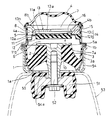
図1は本発明に係る液封入式防振装置の断面図、図2はダイヤフラムと仕切部の分離した一部欠截斜視図、図3は筒状本体金具、防振基体およびボス金具の一部欠截斜視図である。
【0018】
図において、(1)は底部に開口(1a)を有する底部開放形の略カップ状をなす筒状本体金具、(2)は前記筒状本体金具(1)の内方の軸心部に配されかつ上端部が傘形に広がった径大のフランジ部(2a)を有するボス金具、(3)は前記筒状本体金具(1)の下部、例えば下端部内周面と前記ボス金具(2)の上部との間に加硫接着手段によりシール状態に固着されて介設されたゴム弾性体よりなる防振基体である。前記筒状本体金具(1)とボス金具(2)とは、前記防振基体(3)を介して結合され、前記筒状本体金具(1)の底部開口(1a)が閉塞されている。(4)は前記筒状本体金具(1)の上端部(1b)に前記防振基体(3)と対向して上部開口を覆うように結合されたゴム膜よりなるダイヤフラムである。そして、これらの部材により囲まれた内室、すなわち防振基体(3)とダイヤフラム(4)の間の内室には液体が封入されている。
【0019】
さらに、液体が封入された前記内室における前記防振基体(3)とダイヤフラム(4)との間に仕切部(10)が配され、前記内室がボス金具(2)側の主液室(6)とダイヤフラム(4)側の第1副液室(7)とに仕切り構成され、両液室(6)(7)が仕切部(10)の外周部に有するシェイク振動用の第1のオリフィス(8)により連通せしめられている。
【0020】
前記の筒状本体金具(1)は、車体側のフレーム等の支持側部材(53)に対し、図のように該支持側部材(53)の上部に設けられた底部開放形の略カップ状をなす保持筒(54)に圧入手段により連結固定されて支持されるようになっている。もちろん、他の支持手段を前記筒状本体金具(1)の外周に連結固定して支持することもできる。
【0021】
前記ボス金具(2)は、その上端面が前記筒状本体金具(1)の上部開口付近にあって、かつ下端部が筒状本体金具(1)の底部開口(1a)及び保持筒(54)の底部開口(54a)より下方に突出しており、この下端部にエンジン等の振動源側の連結部材(51)がボルト(52)により締結されている。(55)は前記連結部材(51)の外周に付設したゴム部であり、前記保持筒(54)の底部に当接することにより、それ以上の上方への大変位を規制できるようになっている。なお、図1はエンジン等の荷重が負荷されていない状態を示しており、荷重負荷時には前記ゴム部(55)が保持筒(54)の底部から隔離した状態に保持されることになる。
【0022】
また、前記防振基体(3)は、図に示すように下部側ほど径大の厚肉の略傘形をなしており、その上部が前記ボス金具(2)のフランジ部(2a)の下面とシャフト部外周とに加硫接着され、また下端部が前記筒状本体金具(1)の下端部内周に加硫接着されている。筒状本体金具(1)の内周には前記防振基体(3)と一体のゴム層(3a)が装設されている。
【0023】
前記のダイヤフラム(4)は、その外周部が補強用の筒状部材(5)に加硫接着されており、前記筒状本体金具(1)の上端部(1b)に対して、該筒状部材(5)の下端部(5a)がかしめ締結されることにより結合されている。またこのダイヤフラム(4)は、内室の液圧変動に無理なく追随できるように所定の曲率および断面長さを持っている。前記筒状部材(5)の内周には前記ダイヤフラム(4)と一体に加硫接着された所定の厚みの筒状ゴム部(4a)が装設されている。
【0024】
前記仕切部(10)は、図のように中央開口部(11a)に加硫接着手段により固着された弾性膜(12)を備える仕切板部材(11)と、該仕切板部材(11)の前記第1副液室(7)側に対接するように配されたオリフィス部材(13)とよりなる。オリフィス部材(13)は、前記筒状部材(5)の内側に前記筒状ゴム部(4a)を介して圧入嵌着され、また仕切板部材(11)はその外周縁部(11b)が、前記筒状部材(5)の下端部(5a)と筒状本体金具(1)の上端部(1b)とのかしめ締結部に挟着固定されている。(4b)は前記オリフィス部材(13)の外周縁部が当接する位置決め用の段部である。
【0025】
前記オリフィス部材(13)は、その中央板部(13a)の周縁部下面に有するリング状凸部(13b)が、前記弾性膜(12)の周縁部(12a)とシール状態を保持するように対接せしめられており、前記仕切板部材(11)とオリフィス部材(13)の間が内方部とリング状の外方部とに区画されている。外方部には、前記オリフィス部材(13)および前記仕切板部材(11)の外周部と、前記筒状ゴム部(4a)とにより画されて、かつ円周上の一部で遮壁部(14)により塞がれた略リング状の前記第1のオリフィス(8)が形成されている。
【0026】
前記遮壁部(14)はオリフィス部材(13)の一部(13c)と仕切板部材(11)に加硫接着されたゴム部(12b)とにより形成されている。(8a)(8b)はそれぞれ前記第1のオリフィス(8)から主液室(6)および第1副液室(7)への連通部である。
【0027】
また、前記オリフィス部材(13)の中央板部(13a)と前記弾性膜(12)の上面とにより囲まれた内方部の空間が第2副液室(15)として形成されるとともに、前記オリフィス部材(13)の中央板部(13a)に前記第1副液室(7)から第2副液室(15)に通じるこもり音用の第2のオリフィス(16)としての開口が形成されている。
【0028】
前記オリフィス部材(13)の中央板部(13a)に有する第2のオリフィス(16)としての開口は、前記中央板部(13a)のどこにあってもよいが、前記第1オリフィス(8)との連通部(8b)と第2のオリフィス(16)との相互の干渉を防止して安定した特性を確保するために、外周部の前記第1のオリフィス(8)の連通部(8b)の位置とは反対側に、好ましく180度相対向する側に偏心させておくのがよい。この第2オリフィス(16)の位置や開口径は、防振特性等に応じて適宜設定できる。
【0029】
なお、前記の仕切部(10)における仕切板部材(11)はプレス成形された金属板の中央開口部(11a)にゴム弾性膜(12)が加硫接着するのが製造容易であり、また前記オリフィス部材(13)は、アルミニウムやその合金等の金属あるいはセラミック材や合成樹脂材の成形体よりなるものが、寸法精度を出し易く、実施上特に好適である。これにより両部材により形成される第1のオリフィス(8)の断面積の寸法精度を向上できる。
【0030】
上記の構成よりなる本発明の液封入式防振装置は、上記したように、車体側の支持側部材(53)の上部に有する保持筒(54)に筒状本体金具(1)を圧入固定するとともに、エンジン等の振動源側の連結部材(51)をボス金具(2)に連結して、エンジン等を吊り下げ状態に支持して使用する。この支持状態において、エンジン等の振動源側から振動が与えられると、この振動によって防振基体(3)が変形することにより、封入されている液体が、仕切部(10)の外周部に有するシェイク振動用の第1のオリフィス(8)またはオリフィス部材(13)の中央板部(13a)に有する開口による第2のオリフィス(16)を介して、主液室(6)と第1副液室(7)との間、および第1副液室(7)と第2副液室(15)との間で流動し、この第1のオリフィス(8)および第2のオリフィス(16)それぞれの共振特性により、従来よりも広い周波数範囲において動的ばね定数を効果的に低減できることになる。
【0031】
通常、外周部の前記第1のオリフィス(8)は、シェイク振動の周波数域で振動減衰作用を効果的に発揮されるように設定されているが、これに加えて、第1副液室(7)の側に、こもり音用の第2のオリフィス(16)を介して第2副液室(15)が設けられているので、シェイク振動の周波数域(10〜15Hz)に対して高い周波数域(100〜200Hz)においても動的ばね定数を低減できることになり、以て、かなり広い周波数範囲で振動減衰を効果的になし、騒音防止効果を高めることができる。
【0032】
また、前記第1のオリフィス(8)を、仕切板部材(11)とオリフィス部材(13)とにより形成し、その一方のオリフィス部材(13)を、アルミニウムやその合金等の金属あるいはセラミック材や合成樹脂材の成形体を利用することにより、前記オリフィス(8)の断面積の寸法精度を向上でき、特性のバラつきを減少できる。
【0033】
さらに、こもり音用の前記2のオリフィス(16)の位置を、前記第1のオリフィス(8)の連通部(8b)とは反対側に偏心させて設けておくことにより、両オリフィス(8)(16)の相互の干渉を防止でき、さらに特性を安定させることができる。また、第2のリフィス(16)の開口が偏心してもうけられていると、第1副液室(7)の減圧縮小時にダイヤフラム(4)の中央部がオリフィス部材(13)の中央板部(13a)に当接しても、第2のオリフィス(16)を閉塞することがなく、特性を損なうこともない。
【0034】
【発明の効果】
上記したように本発明の液封入式防振装置によれば、シェイク振動に対応する外周部のオリフィスの寸法精度を向上できて、特性のバラつきを減少でき、また一つのオリフィスと弾性膜とによる場合に比して、高周波数域の動的ばね定数を低減でき、こもり音等の騒音の低減効果にも優れる。
【図面の簡単な説明】
【図1】本発明に係る液封入式防振装置の断面図である。
【図2】同上のダイヤフラムと仕切部材の分離した一部欠截斜視図である。
【図3】同上の筒状本体金具、防振基体およびボス金具の一部欠截斜視図である。
【符号の説明】
(1) 筒状本体金具
(1a) 底部の開口
(1b) 上端部
(2) ボス金具
(2a) フランジ部
(3) 防振基体
(4) ダイヤフラム
(4a) 筒状ゴム部
(4b) 段部
(5) 筒状部材
(5a) 下端部
(6) 主液室
(7) 第1副液室
(8) 第1のオリフィス
(8a)(8b) 連通部
(10) 仕切部
(11)仕切板部材
(11a) 中央開口部
(11b) 外周縁部
(12) 弾性膜
(12a) 周縁部
(12b)ゴム部
(13) オリフィス部材
(13a) 中央板部
(13b) リング状凸部
(13c) 一部
(14) 遮壁部
(15) 第2副液室
(16) 第2のオリフィス
(51) 連結部材
(53)支持側部材
(54) 保持筒[0001]
BACKGROUND OF THE INVENTION
The present invention relates to a liquid-filled vibration isolator used for vibration-proof support of an automobile engine or the like.
[0002]
[Prior art and problems to be solved by the invention]
Conventionally, as a mount for supporting a vibration body such as an automobile engine so that the vibration is not transmitted to the vehicle body or the like, a liquid-filled vibration-proof vibration type in which a liquid is sealed inside a main body portion provided with a vibration-proof base made of a rubber elastic body The device is known.
[0003]
For example, in Japanese Patent Laid-Open No. 7-77234, a vibration-proof base made of a rubber elastic body is attached to one opening of a cylindrical body fitting, and a diaphragm made of a rubber film is attached to the other opening in a sealed state. In addition, the liquid is sealed in the inner chamber surrounded by these, and a partition member having an orifice on the outer peripheral portion is disposed between the vibration-proof base and the diaphragm to partition the chamber into two upper and lower chambers. A liquid-filled vibration isolator communicated by an orifice on the outer periphery of a member is disclosed.
[0004]
This liquid-filled vibration isolator is used by connecting a boss bracket fixed to the shaft center portion of the vibration isolator base to the vibration source side and connecting the cylindrical main body bracket to the support side. The vibration damping function and the vibration insulation function are exhibited by the liquid flow effect of both liquid chambers and the vibration absorption effect of the vibration-proof substrate. Usually, the orifice has a cross-sectional area so that an effective vibration damping function can be exhibited in the frequency range (10 to 15 Hz) of shake vibration.
[0005]
By the way, in such a liquid filled type vibration isolator, in order to obtain stable product characteristics without variation, it is an important factor that the cross-sectional area of the shake vibration orifice is set to a desired dimension.
[0006]
However, the partition member of the vibration isolator disclosed above is formed by forming a concave groove in the outer peripheral portion by press molding from a single steel plate or the like, and is pressed into the cylindrical main body metal fitting to thereby form the cylindrical main body metal fitting. An orifice is formed between the inner peripheral surface of each of the two. Therefore, the dimensional accuracy of the cross-sectional area is not so high, and the product characteristics are likely to vary.
[0007]
Further, although the partition member has an elastic film attached to the central region thereof by vulcanization bonding means, the dynamic spring constant is reduced by the one orifice (for shake vibration) and the elastic film. Therefore, it has been difficult to obtain the effect of reducing the dynamic spring constant in a relatively high frequency range (100 to 200 Hz) such as vibration that generates a booming noise.
[0008]
The present invention has been made in view of the above, can improve the dimensional accuracy of the orifice of the outer peripheral portion corresponding to the shake vibration, can reduce the variation in characteristics, and can reduce the dynamic spring constant in the high frequency range, It is an object of the present invention to provide a liquid-filled vibration isolator that is also excellent in reducing noise such as booming noise.
[0009]
[Means for Solving the Problems]
The liquid-filled vibration isolator according to the present invention includes a rubber elastic body between a lower part of a cylindrical main body metal fitting having a substantially cup shape with an open bottom and a boss metal fitting arranged on an inner axial center part thereof. The lower opening is closed through a vibration isolating substrate, and a rubber film diaphragm is connected to the upper end of the cylindrical body fitting so as to cover the upper opening. Liquid is enclosed, and a partition portion is disposed between the vibration-proof base and the diaphragm, and the inner chamber is configured to be partitioned into a main liquid chamber on the boss fitting side and a first sub liquid chamber on the diaphragm side, A liquid-filled vibration isolator in which both liquid chambers are communicated with each other by an orifice, wherein the partition portion includes a partition plate member having a central portion made of an elastic film, and the first sub liquid chamber side of the partition plate member An orifice member disposed so as to be in contact with the peripheral edge of the elastic membrane. The orifice member and the outer peripheral portion of the partition plate member and the cylindrical rubber portion connected to the diaphragm form a first orifice having a substantially ring shape, and the central plate portion of the orifice member and the elastic film A space surrounded by the upper surface of the second sub-liquid chamber is formed as a second sub-liquid chamber, and the second plate for the booming sound that communicates from the first sub-liquid chamber to the second sub-liquid chamber in the central plate portion of the orifice member. An opening as an orifice is formed.
[0010]
Thereby, in addition to the first orifice at the outer peripheral portion corresponding to the shake vibration, the second orifice for the booming noise connected to the second sub liquid chamber is provided on the first sub liquid chamber side. Therefore, the dynamic spring constant can be reduced even in a high frequency range (100 to 200 Hz) compared to the above, and vibration damping can be effectively performed in a wide frequency range, and the noise prevention effect can be enhanced. In addition, since the first orifice is formed by the partition plate member and the orifice member, it becomes possible to easily use the molded body for one of them, and the dimensional accuracy of the sectional area of the orifice can be improved, and the characteristics can be improved. The variation can be reduced.
[0011]
In the liquid filled type vibration damping device of the present invention , in the above-described configuration, an opening is further provided as a second orifice provided in the central plate portion of the orifice member from the first orifice provided in the outer peripheral portion of the orifice member . It is decentered on the side opposite to the position of the communicating part to the sub liquid chamber . As a result, mutual interference between the first and second orifices can be prevented, and the characteristics can be further stabilized. Further, even if the central portion of the diaphragm contacts the central plate portion of the orifice member when the first sub-liquid chamber is reduced in pressure, the second orifice is not blocked.
[0012]
In the liquid filled type vibration damping device, the partition plate member in the partition portion is formed by vulcanizing and bonding a rubber elastic film to a central opening of a press-molded metal plate, and the orifice member is made of metal , ceramic material or What consists of a molding of a synthetic resin material is suitable. Thereby, the dimensional accuracy of an orifice can be improved.
[0013]
Further, in the liquid-filled vibration isolator, the diaphragm is vulcanized and bonded to a cylindrical member fastened to an upper end opening of the cylindrical main body metal fitting, and a cylinder integral with the diaphragm is provided on an inner periphery of the cylindrical member. A rubber part is provided, and the orifice member and the partition plate member of the partition part are fitted to the inner periphery of the cylindrical rubber part to form the first orifice. . Thereby, the coupling strength of the diaphragm can be increased.
[0014]
Further, the first orifice has a substantially ring shape in which a part of a path on the circumference surrounded by the outer periphery of the partition plate member and the orifice member and the cylindrical rubber portion is closed by the shielding wall portion, The shielding wall portion may be formed by a part of the orifice member and a rubber portion vulcanized and bonded to the partition plate member.
[0015]
The liquid-filled vibration isolator is used with the boss fitting connected to a vibration source side member such as an engine, and the cylindrical body fitting connected to a support side member such as a vehicle body.
[0016]
DETAILED DESCRIPTION OF THE INVENTION
Next, embodiments of the present invention will be described based on examples shown in the drawings.
[0017]
FIG. 1 is a cross-sectional view of a liquid-filled vibration isolator according to the present invention, FIG. 2 is a partially broken perspective view with a diaphragm and a partition part separated, and FIG. 3 shows one of a cylindrical main body metal fitting, a vibration isolator base, and a boss metal fitting. FIG.
[0018]
In the figure, (1) is an open bottom cylindrical body fitting having an opening (1a) at the bottom, and (2) is arranged on the inner axial center of the cylindrical body fitting (1). A boss fitting having a large-diameter flange portion (2a) having an upper end spread in an umbrella shape, (3) is a lower portion of the cylindrical main body fitting (1), for example, the inner peripheral surface of the lower end portion and the boss fitting (2) A vibration-proof base made of a rubber elastic body interposed between the upper part of the rubber member and the upper part of the rubber member in a sealed state by a vulcanizing adhesive means. The cylindrical body fitting (1) and the boss fitting (2) are coupled via the vibration-proof base (3), and the bottom opening (1a) of the cylindrical body fitting (1) is closed. (4) is a diaphragm made of a rubber film coupled to the upper end portion (1b) of the cylindrical main body metal fitting (1) so as to face the vibration isolating base (3) and cover the upper opening. A liquid is sealed in the inner chamber surrounded by these members, that is, the inner chamber between the vibration isolating base (3) and the diaphragm (4).
[0019]
Furthermore, a partition portion (10) is disposed between the vibration-proof base (3) and the diaphragm (4) in the inner chamber in which the liquid is sealed, and the inner chamber is a main liquid chamber on the boss fitting (2) side. (6) and is a partition configured diaphragm (4) of the first sub-liquid chamber (7), first for shake vibration having an outer peripheral portion of the Ryoekishitsu (6) (7) the partition portion (10) The orifice (8) is connected.
[0020]
The cylindrical body fitting (1) is substantially cup-shaped with an open bottom portion provided on the upper side of the support side member ( 53 ) as shown in the figure with respect to the support side member ( 53 ) such as a frame on the vehicle body side. The holding cylinder ( 54 ) is connected and fixed by press-fitting means to be supported. Of course, other support means can be connected and fixed to the outer periphery of the cylindrical body fitting (1).
[0021]
The upper end surface of the boss fitting (2) is in the vicinity of the upper opening of the cylindrical main body fitting (1), and the lower end is the bottom opening (1a) of the cylindrical main body fitting (1) and the holding cylinder ( 54 ). ) Projecting downward from the bottom opening ( 54a ), and a connecting member ( 51 ) on the vibration source side of the engine or the like is fastened to the lower end portion by a bolt ( 52 ). (55) is a rubber part attached to the outer periphery of the connecting member ( 51 ), and by contacting the bottom part of the holding cylinder ( 54 ), further large displacement can be restricted. . FIG. 1 shows a state in which a load of the engine or the like is not applied. When the load is applied, the rubber part (55) is held in a state of being isolated from the bottom of the holding cylinder ( 54 ).
[0022]
The anti-vibration base (3) has a thick, substantially umbrella shape with a larger diameter on the lower side as shown in the figure, and the upper part is the lower surface of the flange part (2a) of the boss fitting (2). And the outer periphery of the shaft portion are vulcanized and bonded, and the lower end portion is vulcanized and bonded to the inner periphery of the lower end portion of the cylindrical body fitting (1). A rubber layer (3a) integral with the vibration-proof base (3) is provided on the inner periphery of the cylindrical body fitting (1).
[0023]
The outer periphery of the diaphragm (4) is vulcanized and bonded to a reinforcing tubular member (5), and the tubular shape is attached to the upper end (1b) of the tubular body fitting (1). The lower end (5a) of the member (5) is joined by caulking and fastening. Moreover, this diaphragm (4) has a predetermined curvature and cross-sectional length so that it can follow the fluid pressure fluctuation of the inner chamber without difficulty. A cylindrical rubber part (4a) having a predetermined thickness, which is integrally vulcanized and bonded to the diaphragm (4), is provided on the inner periphery of the cylindrical member (5).
[0024]
The partition (10) includes a partition plate member (11) having an elastic membrane (12) fixed to the central opening (11a) by vulcanization bonding means as shown in the figure, and the partition plate member (11). And an orifice member (13) arranged to contact the first sub-liquid chamber (7). The orifice member (13) is press-fitted inside the cylindrical member (5) via the cylindrical rubber part (4a), and the partition plate member (11) has an outer peripheral edge part (11b). The cylindrical member (5) is clamped and fixed to a caulking fastening portion between the lower end portion (5a) of the cylindrical member (5) and the upper end portion (1b) of the cylindrical main body fitting (1). (4b) is a positioning step where the outer peripheral edge of the orifice member (13) contacts.
[0025]
The orifice member (13) has a ring-shaped convex part (13b) on the lower surface of the peripheral part of the central plate part (13a) so that the peripheral part (12a) of the elastic film (12) is kept in a sealed state. The partition plate member (11) and the orifice member (13) are partitioned into an inner portion and a ring-shaped outer portion. The outer portion is defined by the outer peripheral portion of the orifice member (13) and the partition plate member (11) and the cylindrical rubber portion (4a), and is a shielding portion at a part on the circumference. A substantially ring-shaped first orifice (8) closed by (14) is formed.
[0026]
The shielding wall part (14) is formed by a part (13c) of the orifice member (13) and a rubber part ( 12b ) vulcanized and bonded to the partition plate member (11). (8a) and (8b) are communication portions from the first orifice (8) to the main liquid chamber (6) and the first sub liquid chamber (7), respectively.
[0027]
In addition, an inner space surrounded by the central plate portion (13a) of the orifice member (13) and the upper surface of the elastic membrane (12) is formed as a second auxiliary liquid chamber (15), and An opening as a second orifice (16) for a booming sound that communicates from the first sub liquid chamber (7) to the second sub liquid chamber (15) is formed in the central plate portion (13a) of the orifice member (13). ing.
[0028]
The opening as the second orifice (16) in the central plate portion (13a) of the orifice member (13) may be anywhere in the central plate portion (13a), but the first orifice (8) and In order to prevent mutual interference between the communication portion ( 8b ) and the second orifice (16) and to ensure stable characteristics, the communication portion (8b) of the first orifice (8) on the outer peripheral portion It is preferable to decenter it on the side opposite to the position, preferably on the side opposite to it by 180 degrees. The position and opening diameter of the second orifice (16) can be set as appropriate according to the vibration isolation characteristics and the like.
[0029]
The partition plate member (11) in the partition portion (10) is easy to manufacture because the rubber elastic membrane (12) is vulcanized and bonded to the central opening (11a) of the press-formed metal plate. The orifice member (13) is made of a metal such as aluminum or an alloy thereof, or a molded body of a ceramic material or a synthetic resin material. Thereby, the dimensional accuracy of the cross-sectional area of the first orifice (8) formed by both members can be improved.
[0030]
As described above, in the liquid-filled vibration isolator of the present invention having the above-described configuration, the cylindrical main body fitting (1) is press-fitted and fixed to the holding cylinder ( 54 ) provided on the upper portion of the support-side member ( 53 ) on the vehicle body side. At the same time, the connecting member ( 51 ) on the vibration source side of the engine or the like is connected to the boss fitting (2), and the engine or the like is supported and used in a suspended state. In this supported state, when vibration is applied from the vibration source side of the engine or the like, the vibration-isolating base (3) is deformed by the vibration, so that the sealed liquid has on the outer peripheral portion of the partition (10). The main liquid chamber (6) and the first auxiliary liquid are passed through the first orifice (8) for shake vibration or the second orifice (16) having an opening in the central plate portion (13a) of the orifice member (13). Between the chamber (7) and between the first sub liquid chamber (7) and the second sub liquid chamber (15), the first orifice (8) and the second orifice (16), respectively. With this resonance characteristic, the dynamic spring constant can be effectively reduced in a wider frequency range than before.
[0031]
Usually, the first orifice (8) in the outer peripheral portion is set so as to effectively exhibit a vibration damping action in the frequency range of the shake vibration, but in addition to this, the first sub liquid chamber ( Since the second auxiliary liquid chamber (15) is provided on the side of 7) via the second orifice (16) for booming noise, the frequency is higher than the frequency range of shake vibration (10 to 15 Hz). Even in the region (100 to 200 Hz), the dynamic spring constant can be reduced. Therefore, vibration damping can be effectively performed in a considerably wide frequency range, and the noise prevention effect can be enhanced.
[0032]
The first orifice (8) is formed by a partition plate member (11) and an orifice member (13), and one of the orifice members (13) is made of a metal such as aluminum or an alloy thereof, a ceramic material, By using the molded body of the synthetic resin material, the dimensional accuracy of the sectional area of the orifice (8) can be improved, and the variation in characteristics can be reduced.
[0033]
Further, by setting the position of the two orifices (16) for the booming sound so as to be eccentric to the side opposite to the communication portion (8b) of the first orifice (8), both the orifices (8) are provided. The mutual interference of (16) can be prevented, and the characteristics can be further stabilized. Further, if the opening of the second reflex (16) is made eccentric, the central portion of the diaphragm (4) becomes the central plate portion (13) of the orifice member (13) when the first secondary liquid chamber (7) is reduced in pressure. Even if it abuts against 13a), the second orifice (16) is not blocked and the characteristics are not impaired.
[0034]
【The invention's effect】
As described above, according to the liquid-filled vibration isolator of the present invention, it is possible to improve the dimensional accuracy of the orifice at the outer periphery corresponding to the shake vibration, to reduce the variation in characteristics, and to use one orifice and the elastic film. Compared to the case, the dynamic spring constant in the high frequency range can be reduced, and the effect of reducing noise such as booming noise is excellent.
[Brief description of the drawings]
FIG. 1 is a cross-sectional view of a liquid-filled vibration isolator according to the present invention.
FIG. 2 is a partially broken perspective view in which the diaphragm and the partition member are separated.
FIG. 3 is a partially broken perspective view of the cylindrical main body metal fitting, the vibration isolating base, and the boss metal fitting.
[Explanation of symbols]
(1) Cylindrical body fitting (1a) Bottom opening (1b) Upper end (2) Boss fitting (2a) Flange (3) Anti-vibration base (4) Diaphragm (4a) Cylindrical rubber part (4b) Step (5) Tubular member (5a) Lower end part (6) Main liquid chamber (7) First sub liquid chamber (8) First orifice (8a) (8b) Communication part (10) Partition part
(11) Partition member (11a) Central opening (11b) Outer peripheral edge (12) Elastic membrane (12a) Peripheral part
(12b) Rubber part (13) Orifice member (13a) Center plate part (13b) Ring-shaped convex part (13c) Part (14) Shielding wall part (15) Second sub liquid chamber (16) Second orifice ( 51) Connecting member
(53) Support side member ( 54 ) Holding cylinder
Claims (5)
前記仕切部は、中央部が弾性膜(12)よりなる仕切板部材(11)と、該仕切板部材の前記第1副液室側に前記弾性膜と対向して当該弾性膜の周縁部(12a)と対接するように配されたオリフィス部材(13)とよりなり、該オリフィス部材および前記仕切板部材の外周部と、前記ダイヤフラムに連なる筒状ゴム部(4a)とにより略リング状をなす前記第1のオリフィスが形成され、また前記オリフィス部材の中央板部(13a)と前記弾性膜の上面とにより囲まれた空間が第2副液室(15)として形成されるとともに、前記オリフィス部材の中央板部に前記第1副液室から前記第2副液室に通じるこもり音用の第2のオリフィス(16)としての開口が形成され、該第2のオリフィス(16)としての開口が、前記オリフィス部材(13)の外周部に設けられた第1のオリフィスから第1副液室への連通部(8b)の位置とは反対側に偏心せしめられてなることを特徴とする液封入式防振装置。An anti-vibration base body comprising a rubber elastic body between a lower part of a cylindrical main body metal fitting (1) having a substantially cup shape with an open bottom and a boss metal fitting (2) disposed on an inner axial center portion thereof (3) , a diaphragm (4) made of a rubber film is joined to the upper part of the cylindrical body fitting so as to cover the upper opening, and a liquid is enclosed in the inner chamber between the vibration-proof base and the diaphragm. together with the said vibration-isolating base and the partition portion between the diaphragm (10) is arranged, said chamber main liquid chamber of the boss metal fitting side (6) and the first auxiliary fluid chamber diaphragm side (7) And a liquid-filled vibration isolator in which both liquid chambers are communicated by the first orifice (8) ,
The partition portion includes a partition plate member (11) having a central portion made of an elastic membrane (12), and a peripheral portion of the elastic membrane facing the elastic membrane on the first sub liquid chamber side of the partition plate member ( 12a) and an orifice member (13) arranged so as to be in contact with each other. The outer peripheral part of the orifice member and the partition plate member and the cylindrical rubber part (4a) connected to the diaphragm form a substantially ring shape. The first orifice is formed, and a space surrounded by the central plate portion (13a) of the orifice member and the upper surface of the elastic membrane is formed as a second auxiliary liquid chamber (15) , and the orifice member the second opening of the orifice (16) for rumble communicating with the second auxiliary liquid chamber to the central plate portion from said first auxiliary liquid chamber is formed, the opening of the second as an orifice (16) , the orifice member Hydraulic antivibration device characterized by comprising been brought eccentrically on the side opposite to the position of the communication portion (8b) from a first orifice provided in the outer peripheral portion to the first sub liquid chamber 13).
Priority Applications (3)
| Application Number | Priority Date | Filing Date | Title |
|---|---|---|---|
| JP2000165976A JP3858141B2 (en) | 2000-06-02 | 2000-06-02 | Liquid-filled vibration isolator |
| US09/980,903 US6648312B2 (en) | 2000-06-02 | 2001-04-20 | Liquid-sealed antivibration device |
| PCT/JP2001/003421 WO2001094809A1 (en) | 2000-06-02 | 2001-04-20 | Liquid seal type vibration isolator |
Applications Claiming Priority (1)
| Application Number | Priority Date | Filing Date | Title |
|---|---|---|---|
| JP2000165976A JP3858141B2 (en) | 2000-06-02 | 2000-06-02 | Liquid-filled vibration isolator |
Publications (3)
| Publication Number | Publication Date |
|---|---|
| JP2001349368A JP2001349368A (en) | 2001-12-21 |
| JP2001349368A5 JP2001349368A5 (en) | 2006-06-15 |
| JP3858141B2 true JP3858141B2 (en) | 2006-12-13 |
Family
ID=18669366
Family Applications (1)
| Application Number | Title | Priority Date | Filing Date |
|---|---|---|---|
| JP2000165976A Expired - Lifetime JP3858141B2 (en) | 2000-06-02 | 2000-06-02 | Liquid-filled vibration isolator |
Country Status (3)
| Country | Link |
|---|---|
| US (1) | US6648312B2 (en) |
| JP (1) | JP3858141B2 (en) |
| WO (1) | WO2001094809A1 (en) |
Families Citing this family (9)
| Publication number | Priority date | Publication date | Assignee | Title |
|---|---|---|---|---|
| JP3858141B2 (en) | 2000-06-02 | 2006-12-13 | 東洋ゴム工業株式会社 | Liquid-filled vibration isolator |
| JP2002070924A (en) * | 2000-08-24 | 2002-03-08 | Toyo Tire & Rubber Co Ltd | Liquid-sealed vibration control device |
| JP3590904B2 (en) * | 2001-04-16 | 2004-11-17 | 東洋ゴム工業株式会社 | Anti-vibration device |
| EP1316741A1 (en) * | 2001-11-28 | 2003-06-04 | Toyo Tire & Rubber Co., Ltd . | Liquid-sealed antivibration device |
| JP4134756B2 (en) * | 2003-02-28 | 2008-08-20 | 東海ゴム工業株式会社 | Rubber stopper in liquid ring engine mount |
| JP4842078B2 (en) * | 2006-01-31 | 2011-12-21 | 東海ゴム工業株式会社 | Fluid-filled vibration isolator and manufacturing method thereof |
| JP4603015B2 (en) * | 2007-06-21 | 2010-12-22 | 東洋ゴム工業株式会社 | Liquid-filled vibration isolator |
| JP2010169225A (en) * | 2009-01-26 | 2010-08-05 | Bridgestone Corp | Vibration control device |
| JP6122376B2 (en) * | 2013-10-25 | 2017-04-26 | 東洋ゴム工業株式会社 | Vibration isolator |
Family Cites Families (12)
| Publication number | Priority date | Publication date | Assignee | Title |
|---|---|---|---|---|
| US4651980A (en) * | 1984-02-21 | 1987-03-24 | Honda Giken Kogyo Kabushiki Kaisha | Vibration isolator |
| JP2612783B2 (en) | 1991-04-19 | 1997-05-21 | 東海ゴム工業株式会社 | Fluid-filled mounting device |
| JP2510903B2 (en) * | 1991-06-03 | 1996-06-26 | 東海ゴム工業株式会社 | Fluid-filled mount device and manufacturing method thereof |
| JP3472883B2 (en) | 1993-06-25 | 2003-12-02 | 東洋ゴム工業株式会社 | Liquid-filled anti-vibration mount |
| JP3461913B2 (en) | 1994-06-20 | 2003-10-27 | 株式会社ブリヂストン | Anti-vibration device |
| JP3166493B2 (en) * | 1994-06-28 | 2001-05-14 | 豊田合成株式会社 | Liquid filled vibration isolator |
| JPH109333A (en) | 1996-06-27 | 1998-01-13 | Bridgestone Corp | Vibration isolating device |
| JP3051950B2 (en) * | 1996-07-26 | 2000-06-12 | 東洋ゴム工業株式会社 | Liquid filled vibration isolator and method of assembling the same |
| US6082718A (en) | 1997-03-03 | 2000-07-04 | Toyoda Gosei Co., Ltd. | Liquid-sealing type vibration isolating apparatus |
| FR2778713B1 (en) | 1998-05-13 | 2000-08-04 | Peugeot | PROCESS FOR PRODUCING AN INTERMEDIATE PLATE OF A HYDROELASTIC SUPPORT AND INTERMEDIATE PLATE OBTAINED BY THIS PROCESS |
| JP3858141B2 (en) | 2000-06-02 | 2006-12-13 | 東洋ゴム工業株式会社 | Liquid-filled vibration isolator |
| JP2002070924A (en) * | 2000-08-24 | 2002-03-08 | Toyo Tire & Rubber Co Ltd | Liquid-sealed vibration control device |
-
2000
- 2000-06-02 JP JP2000165976A patent/JP3858141B2/en not_active Expired - Lifetime
-
2001
- 2001-04-20 WO PCT/JP2001/003421 patent/WO2001094809A1/en active Application Filing
- 2001-04-20 US US09/980,903 patent/US6648312B2/en not_active Expired - Fee Related
Also Published As
| Publication number | Publication date |
|---|---|
| WO2001094809A1 (en) | 2001-12-13 |
| JP2001349368A (en) | 2001-12-21 |
| US6648312B2 (en) | 2003-11-18 |
| US20020158391A1 (en) | 2002-10-31 |
Similar Documents
| Publication | Publication Date | Title |
|---|---|---|
| JP3489500B2 (en) | Anti-vibration device | |
| JP3697565B2 (en) | Liquid-filled vibration isolator | |
| JP2505503Y2 (en) | Fluid-filled mounting device | |
| JPH03121327A (en) | Fluid sealed type cylindrical mount apparatus | |
| JP3915531B2 (en) | Fluid filled anti-vibration mount | |
| JP3858141B2 (en) | Liquid-filled vibration isolator | |
| JP3666484B2 (en) | Liquid-filled vibration isolator | |
| US20010004141A1 (en) | Hydraulic vibration isolator | |
| JP4220099B2 (en) | Controlled liquid filled vibration isolator | |
| JP4220107B2 (en) | Controlled liquid-filled vibration isolator | |
| JP4544783B2 (en) | Liquid seal vibration isolator | |
| JP3767323B2 (en) | Fluid filled vibration isolator | |
| JP2002070924A (en) | Liquid-sealed vibration control device | |
| JPH0236813B2 (en) | ||
| JPH109333A (en) | Vibration isolating device | |
| JP4187137B2 (en) | Liquid-filled vibration isolator | |
| JP4138165B2 (en) | Liquid-filled vibration isolator | |
| JP3823274B2 (en) | Liquid filled anti-vibration mount | |
| JPH0389043A (en) | Fluid-filled vibration isolating mount | |
| JP4018366B2 (en) | Fluid filled mount | |
| JP4434500B2 (en) | Liquid filled mount | |
| JPH1038011A (en) | Liquid seal type vibration control device | |
| JP3545474B2 (en) | Anti-vibration device | |
| JP3934294B2 (en) | Liquid filled vibration isolator | |
| JP2002206587A (en) | Liquid sealing type vibration control device |
Legal Events
| Date | Code | Title | Description |
|---|---|---|---|
| A621 | Written request for application examination |
Free format text: JAPANESE INTERMEDIATE CODE: A621 Effective date: 20050725 |
|
| A521 | Request for written amendment filed |
Free format text: JAPANESE INTERMEDIATE CODE: A523 Effective date: 20060425 |
|
| A871 | Explanation of circumstances concerning accelerated examination |
Free format text: JAPANESE INTERMEDIATE CODE: A871 Effective date: 20060425 |
|
| A975 | Report on accelerated examination |
Free format text: JAPANESE INTERMEDIATE CODE: A971005 Effective date: 20060614 |
|
| A131 | Notification of reasons for refusal |
Free format text: JAPANESE INTERMEDIATE CODE: A131 Effective date: 20060620 |
|
| A521 | Request for written amendment filed |
Free format text: JAPANESE INTERMEDIATE CODE: A523 Effective date: 20060726 |
|
| TRDD | Decision of grant or rejection written | ||
| A01 | Written decision to grant a patent or to grant a registration (utility model) |
Free format text: JAPANESE INTERMEDIATE CODE: A01 Effective date: 20060829 |
|
| A61 | First payment of annual fees (during grant procedure) |
Free format text: JAPANESE INTERMEDIATE CODE: A61 Effective date: 20060904 |
|
| R150 | Certificate of patent or registration of utility model |
Free format text: JAPANESE INTERMEDIATE CODE: R150 |
|
| FPAY | Renewal fee payment (event date is renewal date of database) |
Free format text: PAYMENT UNTIL: 20120929 Year of fee payment: 6 |