JP3856511B2 - Gantry for positron CT system - Google Patents
Gantry for positron CT system Download PDFInfo
- Publication number
- JP3856511B2 JP3856511B2 JP33309496A JP33309496A JP3856511B2 JP 3856511 B2 JP3856511 B2 JP 3856511B2 JP 33309496 A JP33309496 A JP 33309496A JP 33309496 A JP33309496 A JP 33309496A JP 3856511 B2 JP3856511 B2 JP 3856511B2
- Authority
- JP
- Japan
- Prior art keywords
- gantry
- air
- detector
- detector unit
- electronic circuit
- Prior art date
- Legal status (The legal status is an assumption and is not a legal conclusion. Google has not performed a legal analysis and makes no representation as to the accuracy of the status listed.)
- Expired - Fee Related
Links
- 238000001816 cooling Methods 0.000 claims description 84
- 230000005855 radiation Effects 0.000 claims description 5
- 238000010586 diagram Methods 0.000 description 13
- XLYOFNOQVPJJNP-UHFFFAOYSA-N water Substances O XLYOFNOQVPJJNP-UHFFFAOYSA-N 0.000 description 7
- 230000035945 sensitivity Effects 0.000 description 5
- 230000000694 effects Effects 0.000 description 3
- 230000020169 heat generation Effects 0.000 description 3
- 210000004556 brain Anatomy 0.000 description 2
- 239000007788 liquid Substances 0.000 description 2
- 238000000034 method Methods 0.000 description 2
- 229940121896 radiopharmaceutical Drugs 0.000 description 2
- 239000012217 radiopharmaceutical Substances 0.000 description 2
- 230000002799 radiopharmaceutical effect Effects 0.000 description 2
- 239000000853 adhesive Substances 0.000 description 1
- 230000001070 adhesive effect Effects 0.000 description 1
- 229910052797 bismuth Inorganic materials 0.000 description 1
- JCXGWMGPZLAOME-UHFFFAOYSA-N bismuth atom Chemical compound [Bi] JCXGWMGPZLAOME-UHFFFAOYSA-N 0.000 description 1
- 238000007796 conventional method Methods 0.000 description 1
- YBMRDBCBODYGJE-UHFFFAOYSA-N germanium dioxide Chemical compound O=[Ge]=O YBMRDBCBODYGJE-UHFFFAOYSA-N 0.000 description 1
- 238000003384 imaging method Methods 0.000 description 1
- 230000001771 impaired effect Effects 0.000 description 1
- 238000007689 inspection Methods 0.000 description 1
- 230000002503 metabolic effect Effects 0.000 description 1
- 230000004060 metabolic process Effects 0.000 description 1
- 238000005192 partition Methods 0.000 description 1
- 238000010998 test method Methods 0.000 description 1
- 238000009423 ventilation Methods 0.000 description 1
Images


Description
【0001】
【発明の属する技術分野】
本発明は、冷却効率を高めたポジトロンCT装置用ガントリに関するものである。
【0002】
【従来の技術】
ポジトロンCT装置は、ポジトロン放出核種で標識された放射性薬剤を被検体に投与し、被検体内から放出されるポジトロン消滅ガンマ線を被検体の周りにリング状に配置してある検出器で検出することにより、被検体内の放射性薬剤の分布を画像化する装置である。
【0003】
図7はこのようなポジトロンCT装置の一般的なガントリの外観を示す斜視図である。この図7において、1はガントリ全体を示し、1aはガントリカバーを示す。また、2は被検体(図示せず)が挿入,位置決めされる被検体用開口部を示す。
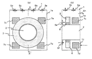
【0004】
図8は図7に示したガントリ1の内部構造の概要を説明するための図で、(a)は正面図、(b)は(a)図中のA−A´断面図である。この図8(a),(b)において、1、1a及び2は図7と同様にガントリ、ガントリカバー及びその被検体用開口部を示す。3は複数個の放射線検出器がリング状に配置されてなる検出器ユニット、6はこの検出器ユニット3が取り付けられた検出器リングベース、7a〜7dは検出器ユニット3からの検出器出力処理用あるいは各回路制御用等の複数個の電子回路機器を備えてなる電子回路機器ユニット、8はスライスコリメータで、これらはガントリカバー1a内に組み込まれている。5a〜5hはガントリ1内部(ガントリカバー1a内)で発生する熱を外部へ放出するための冷却用ファン、71はガントリ1外部(ガントリカバー1a外)の低温空気を内部に取り込むための外部空気取込み口である。
【0005】
図9は図8中の検出器ユニット3、検出器リングベース6及びスライスコリメータ8部分を取り出して示す図である。この図9において、18は検出器ユニット3を構成する検出器で、この検出器18はリング状に密接して配列されている。
【0006】
ところで、一般に、ガントリ1の内部には図8に示すように多くの電子回路機器(電子回路機器ユニット7a〜7d参照)が組み込まれる。通常、それらの電子回路機器はそれらを構成する集積回路チップやその他の電子部品がそれらの最大許容温度を越えることのないような環境の元で使用される。このことは、上記集積回路チップや電子部品の安定な動作の保証及び故障率の低減に重要である。
【0007】
ポジトロンCT装置の場合は、更に、別の観点から使用温度条件を考慮する必要がある。特にポジトロンCT装置において使用される検出器素子(ゲルマニウム酸(化)ビスマスシンチレータ)などは負の温度特性をもち、周囲温度の上昇に伴い出力波高値が低下する傾向を呈す。
【0008】
このため、システム感度が周囲温度に依存し、結果として得られる画像の定量性を損ねることになる。したがって、これらの検出器を含む電子回路機器から発生する熱を放出する必要があるが、これは、ガントリ1のカバー部等に取り付けられた前記冷却用ファン5a〜5hにより内部の高温空気を外部に放出し、一方、外部空気取込み口71から外部の低温空気を内部に取り込むことにより行われている。すなわち従来装置では、電子回路機器等の冷却は強制空冷による熱伝達に基づいて行われている。
【0009】
熱伝達媒体として水等の液体を用いた水冷(液冷)方式の冷却装置を備えたポジトロンCT装置用ガントリもある。
【0010】
【発明が解決しようとする課題】
近年、ポジトロンCT装置の高性能化に伴い、検出器系の電子回路機器の増加及び高密度化が進んでいる。更に、ガントリ1の小形化に伴い、ガントリ1の内部に組み込まれる電子回路機器等の密集化が進んでいる。このため、ガントリ内部で発生する熱の放出を強制空冷方式で行う上述従来技術では、使用する冷却用ファン5a〜5hの数量を増やし、あるいは冷却用ファン5a〜5hの風量を増大させる必要があるため、騒音が増大する。ポジトロンCT装置による脳の代謝検査法においては、周囲の騒音が被検体に影響を及ぼし、検査結果に支障をきたす懸念が生ずる。このため、この種の検査法に関しては、周囲の騒音を可能な限り低く抑えることが要求されるが、上述従来技術における騒音の増大はこれに逆行することとなった。
【0011】
また、冷却用ファン5a〜5hを増加させても、ガントリ内部では図8や図9に示すように、各種の機器が込み入って配置されているため、円滑な空気の流れが確保できず、冷却が不均一になる。このため、強制空冷方式を用いた従来のガントリ1では、検出器ユニット3を一様に冷却することが困難となり、検出器18が取り付けられる位置により感度が変動する要因となった。
【0012】
なお、水冷方式を採用すれば、上記騒音問題は解消できるが、水道設備が必要になること等から構成が複雑になり、更に保全性の低さを含めてコストアップにつながるという問題点があった。
【0013】
本発明の目的は、冷却用ファンの数量増加や風量増大させることなく有効,均一に強制空冷でき、ファン騒音の低減化が図れると共に、検出器感度特性の一様化,これによる画像の定量性の向上が図れるポジトロンCT装置用ガントリを提供することにある。
【0014】
【課題を解決するための手段】
上記目的は、複数個の放射線検出器をリング状に配置してなる検出器ユニットと、この検出器ユニットが取り付けられた検出器リングベースと、複数個の電子回路機器ユニットとをガントリカバーの内部に組み込んでなるポジトロンCT装置用ガントリにおいて、前記ガントリカバーの外部から直接取り込まれた空気を、前記検出器リングベースに沿って通流させて当該検出器リングベースを介して前記検出器ユニット部分と熱交換を行わせた後にガントリカバーの外部へ放出させる空気流路を形成する空気流ガイド及び空気流を発生させるファンを備えてなるリング状の検出器ユニット空冷手段を複数分割されて具備することにより達成される。また、この分割数は、前記検出器ユニットでの熱量に応じて設定される。
【0015】
電子回路機器ユニット空冷手段は、電子回路機器ユニット7の各々に相互に熱的に独立して設けられ、各々ガントリカバー外部から直接取り込まれた空気で電子回路機器ユニットを冷却した後にガントリカバー外部へ直接放出させる。また検出器ユニット強制空冷手段は、電子回路機器ユニット強制空冷手段の各々と熱的に独立して設けられ、ガントリカバー外部から直接取り込まれた空気で検出器ユニットを冷却した後にガントリカバー外部へ直接放出させる。
【0016】
すなわち、冷却対象(各電子回路機器ユニット,検出器ユニット)の空冷手段を熱的に相互に分離独立して設け、一対一対応で各々冷却対象を冷却する。しかも、各々ガントリカバー外部の低温空気を直接取り込んで冷却し、かつ冷却後の高温空気はガントリカバー外部へ直接放出させるものである。
【0017】
これにより、個々の冷却対象の冷却効率が大幅に高められる。また、発熱量の大きい冷却対象から放出される高温空気により比較的発熱量の少ない冷却対象が熱せられたり、他の冷却対象を冷却して温められた高温空気が冷却用に再循環されることもなく、個々の冷却対象は常に外部からの低温空気で冷却される。このため、冷却用ファンの数量増加や風量増大させることなく有効,均一に冷却できる。冷却対象を均一に冷却できることは、特に検出器ユニットについては検出器感度特性の一様化が実現され、画像の定量性が向上されることを意味する。
【0018】
【発明の実施の形態】
以下、図面を参照して本発明の実施形態を説明する。
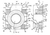
図1は、本発明によるポジトロンCT装置用ガントリの一実施形態の要部を示す構成図で、(a)は正面図、(b)は(a)図中のA−A´断面図である。
この図1(a),(b)において、1、1a、2、3、7a〜7d及び8は各々図8と同様である。
【0019】
100(100a〜100d)は電子回路機器ユニット強制空冷手段で、電子回路機器ユニット7(7a〜7d)の各々に相互に熱的に独立して設けられている。この空冷手段100は、各々ガントリカバー1aの外部から直接取り込まれた空気を、電子回路機器ユニット7部分を経てこの部分と熱交換を行わせた後にガントリカバー1aの外部へ直接放出させる空気流路を形成する空気流ガイドEG1(フード9a,9b)及び空気流を強制的に発生させるファン5を備えてなる。なお、10は外部空気取込み口、11は内部空気放出口を示す。
【0020】
200は検出器ユニット強制空冷手段で、電子回路機器ユニット強制空冷手段100の各々(100a〜100d)と熱的に独立して設けられている。この空冷手段200は、ガントリカバー1aの外部から直接取り込まれた空気を、検出器リングベース6に沿って通流させて当該検出器リングベース6を介して検出器ユニット3部分と熱交換を行わせた後にガントリカバー1aの外部へ直接放出させる空気流路を形成する空気流ガイドEG2(ダクト12、フード13)及び空気流を強制的に発生させるファン(図3中15´参照)を備えてなる。なお、15は外部空気取込み口、矢印は空気流を示す。
【0021】
次に、上記電子回路機器ユニット強制空冷手段100及び検出器ユニット強制空冷手段200の詳細を以下に述べる。
【0022】
図2は図1中の電子回路機器ユニット強制空冷手段100(ここでは100a)を取り出して示す図で、(a)は側面図(図1(a)と同一面側の図)、(b)は正面図((a)図の右側方から見た図)である。この図2において、図1と同一符号は同一又は相当部分を示す。また、PCBは電子回路機器ユニット7を構成する、例えば多数の集積回路チップやその他の電子部品が組み込まれた複数枚のプリント基板(発熱源)である。5k,5l,5mは空冷手段100内において空気流(矢印参照)を強制的に発生させる冷却用ファンである。
【0023】
ここで、電子回路機器ユニット7(7a〜7d)は図1に示すようにガントリカバー1a(ガントリ1)内部に取り付けられが、ガントリカバー1aの外部から空気を取り込みやすいように、またガントリカバー1aの外部へ空気を放出しやすいように、できるだけガントリカバー1a内の外側に設置されている。
【0024】
このような電子回路機器ユニット強制空冷手段100において、ガントリカバー1aの外部の低温空気は、外部空気取込み口10から直接取り込まれ、図中矢印に示すようにフード9aを経て電子回路機器ユニット7(ここでは7a)、すなわち発熱源である複数枚のプリント基板PCB部分に送り込まれてそれらを冷却する。これにより高温となった空気は、図中矢印に示すようにフード9bを経て内部空気放出口11から外部へ直接放出される。
【0025】
各電子回路機器ユニット強制空冷手段100は、電子回路機器ユニット7の各々に相互に熱的に独立して設けられているので熱的に干渉し合わず、また、空気は外部から直接取り込み、かつ外部へ直接放出するので、冷却用ファン5の数量増加や風量増大させることなく有効,均一に強制空冷でき、ファン騒音の低減化が図れる。
【0026】
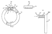
図3は図1中の検出器ユニット強制空冷手段200を取り出して示す図で、(a)は正面図(図1(a)の裏面側から見た図)、(b)は(a)図中のB−B´断面図、(c)は(a)図の右側面図である。この図3において、図1と同一符号は同一又は相当部分を示す。15´は空冷手段200内において空気流(矢印参照)を強制的に発生させる冷却用ファンで、ここでは外部空気取込み口15に取り付けられている。16は内部空気放出口、17はダクト12の仕切板である。外部空気取込み口15,内部空気放出口16は、ダクト12から突出するフード13,13の端部(ガントリカバー1a裏面)に形成されている。
【0027】
ここで、図3(b)に示すように、ダクト12内の検出器リングベース6側の面には、図3(a)中の矢印で示す空気流に沿った方向に複数の冷却フィン14が形成されている。
【0028】
このような検出器ユニット強制空冷手段200において、ガントリカバー1aの外部の低温空気は、外部空気取込み口15から直接取り込まれ、図中矢印に示すようにフード13を経てダクト12内に送り込まれ、検出器リングベース6を介して検出器ユニット3を冷却する。これにより高温となった空気は、図中矢印に示すようにフード13を経て内部空気放出口16から外部へ直接放出される。
【0029】
検出器ユニット強制空冷手段200は、各電子回路機器ユニット強制空冷手段100に相互に熱的に独立して設けられているので熱的に干渉し合わず、また、空気は外部から直接取り込み、かつ外部へ直接放出するので、冷却用ファン15´の数量増加や風量増大させることなく有効,均一に強制空冷でき、ファン騒音の低減化が図れる。
【0030】
なお、図示するように冷却フィン14を設ければ放熱面積が増大し、冷却効率をより高めることができる。ダクト12の断面寸法や、冷却フィン14の高さ、厚さ、間隔等の値は、設定する放熱量に基づき、熱伝達率、周囲温度、検出器リングベース6の温度や質量あるいは通風量等を考慮して、適宜設定する。またフード13として、例えば蛇腹を用いれば、容易にガントリカバー1a内の障害物(各構成部)を回避しながらそれをガントリカバー1a内に組み込むことができる。
【0031】
図4は検出器ユニット強制空冷手段200の他の例を示す図で、(a)は正面図、(b)は(a)図の右側面図である。この図4において、図1と同一符号は同一又は相当部分を示す。図から分かるように、ここでは検出器ユニット強制空冷手段200を4分割構成としたものである。
【0032】
このような4分割構成によれば、ダクト12の通風抵抗による損失が抑えられ、ファン15´として少ない風量のファン、換言すれば低騒音ファンの使用が可能となる。また、分割数をこのように多くすることにより、ダクト入口の空気温度と同出口の空気温度の差(取込み口15,放出口16相互間空気温度差)を小さくすることができ、検出器リングベース6、延いては検出器ユニット3の温度分布をより一様にし得る。
【0033】
図5は検出器ユニット強制空冷手段200の更に異なる例を示す図で、(a)は正面図、(b)は(a)図の右側面図である。この図5において、図1,図4と同一符号は同一又は相当部分を示す。図から分かるように、ここでは検出器ユニット強制空冷手段200を3分割構成としたものである。分割数は発生する検出器ユニット3部分での熱量に応じて適宜決めればよい。
【0034】
図6は水冷方式にて冷却を行うポジトロンCT装置用ガントリの一実施形態を示す構成図で、(a)は側面から示した内部構成図、(b)は裏面から示した内部構成図である。この図6(a),(b)において、1、1a、2、3及び8は各々図1と同様である。20は水冷用熱交換機であり、これにより冷水が配管19を通して循環させられる。
【0035】
ここで配管19は、検出器リングベース6に密着配設されているが、接触面積を可能な限り広くとるため、これを検出器リングベース6に埋め込んだり、あるいは配管19の形状を偏平にする等により熱伝達率(冷却効率)を向上させてもよい。また、熱伝導率の大きい接着剤を介して配管19を検出器リングベース6に取り付けてもよい。更に、配管19を検出器リングベース6面上に複数列並設し、熱伝達特性を向上させてもよい。
【0036】
なお、例えばAC系の電源制御回路や、DCパワーサプライ回路等については、従来と同様に、ガントリカバー1a等に取り付けたファン5a〜5h(図8参照)により冷却すればよい。
【0037】
【発明の効果】
以上説明したように本発明によれば、冷却用ファンの数量増加や風量増大させることなく有効,均一に強制空冷でき、ファン騒音の低減化が図れると共に、検出器感度特性の一様化,これによる画像の定量性の向上が図れるという効果がある。特に、ファン騒音の低減化が図れることによっては、脳の精密な代謝検査に有効で、検査精度を向上させる得る効果がある。
【図面の簡単な説明】
【図1】本発明ガントリの一実施形態の要部を示す構成図である。
【図2】図1中の電子回路機器ユニット強制空冷手段を取り出して示す図である。
【図3】図1中の検出器ユニット強制空冷手段を取り出して示す図である。
【図4】検出器ユニット強制空冷手段の他の例を示す図である。
【図5】検出器ユニット強制空冷手段の他の例を示す図である。
【図6】水冷方式にて冷却を行うポジトロンCT装置用ガントリの一実施形態を示す構成図である。
【図7】ポジトロンCT装置の一般的なガントリの外観を示す斜視図である。
【図8】図7に示したガントリの内部構造の概要を説明するための図である。
【図9】図8中の検出器ユニット、検出器リングベース及びスライスコリメータ部分を取り出して示す図である。
【符号の説明】
1 ガントリ
1a ガントリカバー
2 被検体開口部
3 検出器ユニット
5,5a〜5h,15´ 冷却用ファン
6 検出器リングベース
7,7a〜7d 電子回路機器ユニット
8 スライスコリメータ
9a,9b,13 フード
10,15,71 外部空気取込み口
11 内部空気放出口
12 ダクト
100,100a〜100d 電子回路機器ユニット強制空冷手段
200 検出器ユニット強制空冷手段
EG1,EG2 空気流ガイド[0001]
BACKGROUND OF THE INVENTION
The present invention relates to a gantry for a positron CT apparatus with improved cooling efficiency.
[0002]
[Prior art]
A positron CT device administers a radiopharmaceutical labeled with a positron emitting nuclide to a subject, and detects positron annihilation gamma rays emitted from within the subject with a detector arranged in a ring around the subject. This is an apparatus for imaging the distribution of the radiopharmaceutical in the subject.
[0003]
FIG. 7 is a perspective view showing the appearance of a general gantry of such a positron CT apparatus. In FIG. 7, 1 indicates the entire gantry and 1a indicates a gantry cover.
[0004]
8A and 8B are views for explaining the outline of the internal structure of the gantry 1 shown in FIG. 7, in which FIG. 8A is a front view, and FIG. 8B is a cross-sectional view taken along line AA ′ in FIG. 8A and 8B,
[0005]
FIG. 9 is a diagram showing the detector unit 3, the
[0006]
Incidentally, in general, many electronic circuit devices (see electronic
[0007]
In the case of a positron CT apparatus, it is further necessary to consider operating temperature conditions from another viewpoint. In particular, a detector element (germanic acid (bismuth) scintillator) used in a positron CT apparatus has a negative temperature characteristic, and the output peak value tends to decrease as the ambient temperature increases.
[0008]
For this reason, the system sensitivity depends on the ambient temperature, and the quantitativeness of the resulting image is impaired. Therefore, it is necessary to release the heat generated from the electronic circuit equipment including these detectors. This is because the internal high-temperature air is discharged to the outside by the cooling fans 5a to 5h attached to the cover of the gantry 1 or the like. On the other hand, the external low temperature air is taken into the inside through the external air intake 71. That is, in the conventional apparatus, the cooling of the electronic circuit device or the like is performed based on heat transfer by forced air cooling.
[0009]
There is also a gantry for a positron CT apparatus provided with a water cooling (liquid cooling) type cooling device using a liquid such as water as a heat transfer medium.
[0010]
[Problems to be solved by the invention]
In recent years, with the increase in performance of positron CT apparatuses, the number of detector electronic circuit devices has been increasing and the density has been increasing. Furthermore, along with the downsizing of the gantry 1, the electronic circuit devices and the like incorporated in the gantry 1 are becoming denser. For this reason, in the above-described conventional technique in which the heat generated in the gantry is released by the forced air cooling method, it is necessary to increase the number of cooling fans 5a to 5h to be used or increase the air volume of the cooling fans 5a to 5h. Therefore, noise increases. In the brain metabolism test method using the positron CT apparatus, ambient noise affects the subject, and there is a concern that the test result may be hindered. For this reason, with respect to this type of inspection method, it is required to suppress ambient noise as low as possible, but the increase in noise in the above-described prior art is contrary to this.
[0011]
Even if the cooling fans 5a to 5h are increased, various devices are intricately arranged inside the gantry as shown in FIGS. 8 and 9, so that a smooth air flow cannot be ensured. Becomes uneven. For this reason, in the conventional gantry 1 using the forced air cooling method, it is difficult to uniformly cool the detector unit 3, and the sensitivity varies depending on the position where the
[0012]
If the water cooling method is adopted, the above noise problem can be solved, but the configuration becomes complicated due to the necessity of water supply facilities, etc., and the cost is increased including the low maintainability. It was.
[0013]
An object of the present invention is to enable effective and uniform forced air cooling without increasing the number of cooling fans and air flow, to reduce fan noise, to make the detector sensitivity characteristics uniform, and to thereby make the image quantitative. It is an object to provide a gantry for a positron CT apparatus capable of improving the above.
[0014]
[Means for Solving the Problems]
The object is to provide a detector unit in which a plurality of radiation detectors are arranged in a ring shape, a detector ring base to which the detector unit is attached, and a plurality of electronic circuit device units inside the gantry cover. In the gantry for a positron CT apparatus incorporated in the air, the air directly taken in from the outside of the gantry cover is caused to flow along the detector ring base and the detector unit part through the detector ring base. A plurality of ring-shaped detector unit air cooling means including an air flow guide for forming an air flow path to be discharged to the outside of the gantry cover after heat exchange and a fan for generating an air flow are provided. Is achieved. The number of divisions is set according to the amount of heat in the detector unit.
[0015]
The electronic circuit equipment unit air cooling means is provided thermally independently from each other in each of the electronic
[0016]
That is, air cooling means for cooling objects (each electronic circuit device unit and detector unit) are provided thermally and separately from each other, and each cooling object is cooled in a one-to-one correspondence. Moreover, the low temperature air outside the gantry cover is directly taken in and cooled, and the high temperature air after cooling is directly discharged outside the gantry cover.
[0017]
Thereby, the cooling efficiency of each cooling object is significantly improved. In addition, the high-temperature air released from the cooling target with a large heat generation amount heats the cooling target with a relatively small heat generation amount, or the high-temperature air heated by cooling other cooling targets is recirculated for cooling. In addition, the individual objects to be cooled are always cooled by external cold air. For this reason, effective and uniform cooling can be achieved without increasing the number of cooling fans or increasing the air volume. The ability to uniformly cool the object to be cooled means that the detector sensitivity characteristic is made uniform, particularly for the detector unit, and the quantitativeness of the image is improved.
[0018]
DETAILED DESCRIPTION OF THE INVENTION
Hereinafter, embodiments of the present invention will be described with reference to the drawings.
FIG. 1 is a configuration diagram showing the main part of an embodiment of a gantry for a positron CT apparatus according to the present invention, in which (a) is a front view and (b) is a sectional view taken along line AA ′ in FIG. .
In FIGS. 1A and 1B, 1, 1a, 2, 3, 7a to 7d and 8 are the same as those in FIG.
[0019]
Reference numeral 100 (100a to 100d) denotes an electronic circuit device unit forced air cooling means, and is provided thermally independent of each of the electronic circuit device units 7 (7a to 7d). This air cooling means 100 is an air flow path that directly discharges the air directly taken from the outside of the
[0020]
Reference numeral 200 denotes a detector unit forced air cooling means, which is provided thermally independently from each of the electronic circuit device unit forced air cooling means 100 (100a to 100d). The air cooling means 200 allows air taken directly from the outside of the
[0021]
Next, details of the electronic circuit device unit forced air cooling means 100 and the detector unit forced air cooling means 200 will be described below.
[0022]
FIG. 2 is a view showing the electronic circuit device unit forced air cooling means 100 (here, 100a) in FIG. 1, taken out from the side view (a) is a side view (the same side as FIG. 1 (a)), (b). These are front views (the figure seen from the right side of figure (a)). In FIG. 2, the same reference numerals as those in FIG. 1 denote the same or corresponding parts. The PCB is a plurality of printed circuit boards (heat generation sources) that constitute the electronic
[0023]
Here, the electronic circuit device unit 7 (7a to 7d) is attached to the inside of the
[0024]
In such an electronic circuit device unit forced air cooling means 100, the low-temperature air outside the
[0025]
Each electronic circuit device unit forced air cooling means 100 is provided thermally independent from each other in each electronic
[0026]
3A and 3B are diagrams showing the detector unit forced air cooling means 200 in FIG. 1 taken out, wherein FIG. 3A is a front view (viewed from the back side of FIG. 1A), and FIG. BB 'sectional drawing in the inside, (c) is a right view of (a) figure. 3, the same reference numerals as those in FIG. 1 denote the same or corresponding parts.
[0027]
Here, as shown in FIG. 3 (b), a plurality of cooling fins 14 are arranged on the surface of the
[0028]
In such a detector unit forced air cooling means 200, the low-temperature air outside the
[0029]
The detector unit forced air cooling means 200 is provided in each electronic circuit device unit forced air cooling means 100 thermally independent from each other so that they do not interfere with each other, and air is directly taken in from the outside, and Since it is directly discharged to the outside, it can be effectively and uniformly forced air-cooled without increasing the number of cooling fans 15 'or increasing the air volume, and fan noise can be reduced.
[0030]
In addition, if the cooling fin 14 is provided as shown in the figure, the heat radiation area increases, and the cooling efficiency can be further increased. The cross-sectional dimensions of the
[0031]
4A and 4B are diagrams showing another example of the detector unit forced air cooling means 200, where FIG. 4A is a front view and FIG. 4B is a right side view of FIG. 4, the same reference numerals as those in FIG. 1 denote the same or corresponding parts. As can be seen from the figure, here, the detector unit forced air cooling means 200 has a four-part configuration.
[0032]
According to such a four-divided configuration, loss due to the ventilation resistance of the
[0033]
FIG. 5 is a view showing still another example of the detector unit forced air cooling means 200, in which (a) is a front view and (b) is a right side view of FIG. 5, the same reference numerals as those in FIGS. 1 and 4 denote the same or corresponding parts. As can be seen from the figure, here the detector unit forced air cooling means 200 has a three-part configuration. The number of divisions may be appropriately determined according to the amount of heat generated in the detector unit 3 portion.
[0034]
6A and 6B are configuration diagrams showing an embodiment of a gantry for a positron CT apparatus that performs cooling by a water cooling method, in which FIG. 6A is an internal configuration diagram shown from the side, and FIG. 6B is an internal configuration diagram shown from the back surface. . 6 (a) and 6 (b), 1, 1a, 2, 3 and 8 are the same as those in FIG.
[0035]
Here, the
[0036]
For example, an AC power supply control circuit, a DC power supply circuit, and the like may be cooled by fans 5a to 5h (see FIG. 8) attached to the
[0037]
【The invention's effect】
As described above, according to the present invention, effective and uniform forced air cooling can be performed without increasing the number of cooling fans or increasing the air volume, fan noise can be reduced, and detector sensitivity characteristics can be made uniform. This has the effect of improving the quantitativeness of the image. In particular, the reduction in fan noise is effective for precise metabolic examination of the brain and has the effect of improving examination accuracy.
[Brief description of the drawings]
FIG. 1 is a configuration diagram showing a main part of an embodiment of a gantry according to the present invention.
FIG. 2 is a diagram showing an electronic circuit device unit forced air cooling means in FIG.
FIG. 3 is a diagram showing the detector unit forced air cooling means in FIG.
FIG. 4 is a diagram showing another example of the detector unit forced air cooling means.
FIG. 5 is a diagram showing another example of the detector unit forced air cooling means.
FIG. 6 is a configuration diagram showing an embodiment of a gantry for a positron CT apparatus that performs cooling by a water cooling method.
FIG. 7 is a perspective view showing an external appearance of a general gantry of a positron CT apparatus.
8 is a view for explaining an outline of the internal structure of the gantry shown in FIG. 7;
9 is a view showing a detector unit, a detector ring base, and a slice collimator portion extracted from FIG. 8. FIG.
[Explanation of symbols]
DESCRIPTION OF SYMBOLS 1
Claims (3)
Priority Applications (1)
| Application Number | Priority Date | Filing Date | Title |
|---|---|---|---|
| JP33309496A JP3856511B2 (en) | 1996-11-29 | 1996-11-29 | Gantry for positron CT system |
Applications Claiming Priority (1)
| Application Number | Priority Date | Filing Date | Title |
|---|---|---|---|
| JP33309496A JP3856511B2 (en) | 1996-11-29 | 1996-11-29 | Gantry for positron CT system |
Publications (2)
| Publication Number | Publication Date |
|---|---|
| JPH10160847A JPH10160847A (en) | 1998-06-19 |
| JP3856511B2 true JP3856511B2 (en) | 2006-12-13 |
Family
ID=18262217
Family Applications (1)
| Application Number | Title | Priority Date | Filing Date |
|---|---|---|---|
| JP33309496A Expired - Fee Related JP3856511B2 (en) | 1996-11-29 | 1996-11-29 | Gantry for positron CT system |
Country Status (1)
| Country | Link |
|---|---|
| JP (1) | JP3856511B2 (en) |
Families Citing this family (13)
| Publication number | Priority date | Publication date | Assignee | Title |
|---|---|---|---|---|
| US7065173B2 (en) * | 2003-12-02 | 2006-06-20 | General Electric Company | Method and apparatus for thermal management of CT electronics |
| JP4365762B2 (en) | 2004-09-30 | 2009-11-18 | 株式会社日立製作所 | Nuclear medicine diagnostic apparatus and method for cooling nuclear medicine diagnostic apparatus |
| DE102004055752B4 (en) * | 2004-11-18 | 2007-12-13 | Siemens Ag | CT Scanner |
| JP4764050B2 (en) | 2005-03-31 | 2011-08-31 | 株式会社日立製作所 | Nuclear medicine diagnostic apparatus and method for cooling nuclear medicine diagnostic apparatus |
| JP3942188B2 (en) | 2005-09-30 | 2007-07-11 | 株式会社日立製作所 | Nuclear medicine diagnostic device, positron emission tomography device and detector unit |
| JP2007101234A (en) * | 2005-09-30 | 2007-04-19 | Hitachi Ltd | Nuclear medicine diagnostic equipment, and method of cooling the same |
| JP2007101556A (en) * | 2006-12-04 | 2007-04-19 | Hitachi Ltd | Nuclear medicine diagnosis system, positron emission tomography scanner, and detector unit |
| US8282278B2 (en) * | 2007-11-30 | 2012-10-09 | Koninklijke Philips Electronics N.V. | Gantry cooling |
| JP5972554B2 (en) * | 2011-11-15 | 2016-08-17 | 東芝メディカルシステムズ株式会社 | Nuclear medicine diagnostic equipment |
| JP6312980B2 (en) * | 2012-10-03 | 2018-04-18 | キヤノンメディカルシステムズ株式会社 | X-ray CT system |
| KR101686636B1 (en) | 2015-02-12 | 2016-12-14 | 삼성전자주식회사 | Computed tomography system comprising cooling system |
| KR101722689B1 (en) * | 2015-02-12 | 2017-04-03 | 삼성전자주식회사 | Computed tomography system comprising cooling system |
| JP6498719B2 (en) * | 2017-04-28 | 2019-04-10 | キヤノンメディカルシステムズ株式会社 | X-ray CT system |
-
1996
- 1996-11-29 JP JP33309496A patent/JP3856511B2/en not_active Expired - Fee Related
Also Published As
| Publication number | Publication date |
|---|---|
| JPH10160847A (en) | 1998-06-19 |
Similar Documents
| Publication | Publication Date | Title |
|---|---|---|
| JP3856511B2 (en) | Gantry for positron CT system | |
| US10136551B2 (en) | Liquid cooling system for server | |
| US8422218B2 (en) | Liquid cooled condensers for loop heat pipe like enclosure cooling | |
| TWI596463B (en) | Integrated building based air handler for server farm cooling system | |
| US6903930B2 (en) | Parallel heat exchanger for a component in a mobile system | |
| US20090122483A1 (en) | Water-assisted air cooling for a row of cabinets | |
| CN104812222B (en) | Radiator structure and the electronic installation with the radiator structure | |
| CN109417862A (en) | Circuit board calculates equipment and cooling cabinet | |
| JP2765365B2 (en) | Air conditioner | |
| CN109893157B (en) | PET detector heat radiation structure | |
| CN217062943U (en) | Drawer type power module and modular power cabinet | |
| JP3144135B2 (en) | Electronic equipment | |
| CN210249861U (en) | PET detector heat radiation structure | |
| RU87599U1 (en) | DEVICE HOUSING | |
| TW202246723A (en) | Cold plate and computer system | |
| CN209930798U (en) | Heat abstractor and high-voltage inverter | |
| JP2002271073A (en) | Cooling device for electronic equipment case body | |
| JPS63192256A (en) | Integrated circuit cooling constitution | |
| JP3261820B2 (en) | Heating element mounting board | |
| JP4457238B2 (en) | Heat dissipating structure of heat generating parts in equipment cabinet | |
| CN109240472A (en) | A kind of computer host box with heat dissipation wind channel structure | |
| KR100396783B1 (en) | Device cooling electro-communication apparatus | |
| CN215494905U (en) | Heat radiator | |
| CN211880860U (en) | Equipment assembly, cooling system and equipment rack | |
| JP3691441B2 (en) | Rack mount cooling device |
Legal Events
| Date | Code | Title | Description |
|---|---|---|---|
| A977 | Report on retrieval |
Free format text: JAPANESE INTERMEDIATE CODE: A971007 Effective date: 20051110 |
|
| A131 | Notification of reasons for refusal |
Free format text: JAPANESE INTERMEDIATE CODE: A131 Effective date: 20051121 |
|
| A521 | Request for written amendment filed |
Free format text: JAPANESE INTERMEDIATE CODE: A523 Effective date: 20060118 |
|
| TRDD | Decision of grant or rejection written | ||
| A01 | Written decision to grant a patent or to grant a registration (utility model) |
Free format text: JAPANESE INTERMEDIATE CODE: A01 Effective date: 20060911 |
|
| A61 | First payment of annual fees (during grant procedure) |
Free format text: JAPANESE INTERMEDIATE CODE: A61 Effective date: 20060912 |
|
| R150 | Certificate of patent or registration of utility model |
Free format text: JAPANESE INTERMEDIATE CODE: R150 |
|
| FPAY | Renewal fee payment (event date is renewal date of database) |
Free format text: PAYMENT UNTIL: 20090922 Year of fee payment: 3 |
|
| FPAY | Renewal fee payment (event date is renewal date of database) |
Free format text: PAYMENT UNTIL: 20100922 Year of fee payment: 4 |
|
| LAPS | Cancellation because of no payment of annual fees |