JP3856060B2 - Magnetic recording method and magnetic head - Google Patents
Magnetic recording method and magnetic head Download PDFInfo
- Publication number
- JP3856060B2 JP3856060B2 JP34683497A JP34683497A JP3856060B2 JP 3856060 B2 JP3856060 B2 JP 3856060B2 JP 34683497 A JP34683497 A JP 34683497A JP 34683497 A JP34683497 A JP 34683497A JP 3856060 B2 JP3856060 B2 JP 3856060B2
- Authority
- JP
- Japan
- Prior art keywords
- magnetic
- magnetic field
- recording
- layer
- initialization
- Prior art date
- Legal status (The legal status is an assumption and is not a legal conclusion. Google has not performed a legal analysis and makes no representation as to the accuracy of the status listed.)
- Expired - Fee Related
Links
Images


Classifications
-
- G—PHYSICS
- G11—INFORMATION STORAGE
- G11B—INFORMATION STORAGE BASED ON RELATIVE MOVEMENT BETWEEN RECORD CARRIER AND TRANSDUCER
- G11B5/00—Recording by magnetisation or demagnetisation of a record carrier; Reproducing by magnetic means; Record carriers therefor
- G11B5/02—Recording, reproducing, or erasing methods; Read, write or erase circuits therefor
- G11B5/027—Analogue recording
- G11B5/03—Biasing
-
- G—PHYSICS
- G11—INFORMATION STORAGE
- G11B—INFORMATION STORAGE BASED ON RELATIVE MOVEMENT BETWEEN RECORD CARRIER AND TRANSDUCER
- G11B5/00—Recording by magnetisation or demagnetisation of a record carrier; Reproducing by magnetic means; Record carriers therefor
- G11B5/02—Recording, reproducing, or erasing methods; Read, write or erase circuits therefor
-
- G—PHYSICS
- G11—INFORMATION STORAGE
- G11B—INFORMATION STORAGE BASED ON RELATIVE MOVEMENT BETWEEN RECORD CARRIER AND TRANSDUCER
- G11B5/00—Recording by magnetisation or demagnetisation of a record carrier; Reproducing by magnetic means; Record carriers therefor
- G11B2005/0002—Special dispositions or recording techniques
- G11B2005/0005—Arrangements, methods or circuits
Description
【0001】
【発明の属する技術分野】
本発明は、磁気的に情報を記録する磁気記録方法、及び磁気記録媒体に磁界を印加して情報の記録を行なう磁気ヘッドに関する。
【0002】
【従来の技術】
磁気ディスクは、コンピュータにおける情報記録装置として普及している。とりわけ、動画像を取り扱うPC(personal computer )環境においては、さらなる大容量の記録、即ち高密度記録が可能な磁気ディスクが求められている。記録密度を高めるためには、磁気ディスクに形成する記録マーク長を短くするとともに、トラック幅を狭くする。
【0003】
例えば、基板上にCrからなる下地層とCoCrTaPtからなる記録層が積層された従来の磁気ディスクに情報を記録する。記録層の保磁力は2kOe程度である。この磁気ディスクには、通常の磁気ヘッドを用いて交番磁界を印加することにより記録層に情報を記録することができる。この記録層に微小な記録マークを形成した場合には、記録層の粒子サイズに起因するノイズの上昇が生じる。これを解決するためには記録層の結晶粒を小さくすれば良いが、結晶粒を微小化すると記録された磁化方向が乱れやすくなり、記録層の熱的安定性が低下するという問題があった。
【0004】
【発明が解決しようとする課題】
記録層の熱的安定性を良好にするためには、記録層の保磁力を例えば3kOeまで大きくすれば良い。しかしながら、磁性層の保持力が大きくなると、記録時に印加する交番磁界を大きくする必要があるという問題があった。また短い記録マーク長を形成する場合には、記録周波数が高いために、大きな交番磁界の印加が記録装置に大きな負担をかけるという問題があった。
【0005】
本発明は、かかる事情に鑑みてなされたものであり、大きな保磁力を有する磁性層を備える磁気記録媒体に、小さな交番磁界の印加で情報を記録できる磁気記録方法、及びその方法を実現する磁気ヘッドを提供することを目的とする。なお、以下本願において交番磁界とは、「記録すべき情報に応じた磁化の方向を記録再生層に生じせしめる一方向の磁界の有無で構成する磁界」のことを示す。
【0006】
【課題を解決するための手段】
本発明に係る磁気記録方法は、基板に少なくとも第2の磁性層と第1の磁性層をこの順序で積層し、前記第1の磁性層の保磁力Hc1と前記第2の磁性層の保磁力Hc2との間に、Hc1<Hc2の関係を有する磁気記録媒体に情報を記録する磁気記録方法であって、前記第1及び第2の磁性層の各々の磁化の大きさをMs1、Ms2、各々の膜厚をt1、t2とし、前記第1及び第2の磁性層間の界面磁壁エネルギーをσとした際にHda=Hc2−σ/2Ms2t2、Hab=−Hc1−σ/2Ms1t1、Hbc= - Hc 2 +σ/2Ms2t2によって定義される各値に対して、情報を記録すべき領域に|Hdc1|>|Hda|の関係を満たす第1の初期化磁界Hdc1を印加し、前記第1及び第2の磁性層の磁化方向を同方向に揃える第1初期化過程と、該第1初期化過程後に、前記領域に|Hbc|>|Hdc2|>|Hab|の関係を満たす第2の初期化磁界Hdc2を印加し、前記第1及び第2の磁性層の磁化方向を相異なる方向にする第2初期化過程と、該第2初期化過程後に、記録すべき情報に応じて極性を変化させた交番磁界Hwを前記領域に印加する記録過程とを有することを特徴とする。
但し、|Hc1−σ/2Ms1t1|<|Hw|<|Hab|
【0007】
本発明にあっては、情報を記録保持する第1の磁性層と、該磁性層と交換結合可能な第2の磁性層とを備えており、これらの交換結合領域での磁気特性に基づいて決定された大きさの磁界を印加することにより、記録用交番磁界を印加する直前で第1及び第2の磁性層の磁化方向が所定の方向に向く。この状態の磁性層に交番磁界を印加することにより、第1の磁性層単体の場合よりも小さい磁界の印加で、第1の磁性層の磁化方向を変化させることができる。第1及び第2の磁性層の交換結合領域の磁気特性に基づいて決定された第1の初期化磁界を印加して第1及び第2の磁性層を同方向に揃えた後、第2の初期化磁界を印加して、例えば第1の磁性層の磁化方向を反転させる。この状態の磁性層に交番磁界を印加することにより、第1の磁性層単体に対して必要な大きさよりも小さい磁界の印加で、第1の磁性層の磁化方向を変化させることができる。
【0008】
本発明に係る磁気ヘッドは、基板に少なくとも第2の磁性層と第1の磁性層をこの順序で積層し、前記第1の磁性層の保磁力Hc1と前記第2の磁性層の保磁力Hc2との間に、Hc1<Hc2の関係を有する磁気記録媒体の一面に対向して配され、前記磁気記録媒体に対して相対移動しつつ磁界を印加する磁気ヘッドにおいて、第1の初期化磁界を印加する第1の磁気発生部と第2の初期化磁界を印加する第2の磁気発生部と交番磁界を印加する第3の磁気発生部とを並設してあり、前記磁気発生部の並設方向を前記相対移動の方向と略平行に配すべくなしてあり、前記第1の磁気発生部が印加する前記第1の初期化磁界は、前記第1及び第2の磁性層の各々の磁化の大きさをMs1、Ms2、各々の膜厚をt1、t2とし、前記第1及び第2の磁性層間の界面磁壁エネルギーをσとした際にHda=Hc2−σ/2Ms2t2、Hab=−Hc1−σ/2Ms1t1、Hbc=-Hc2+σ/2Ms2t2によって定義される各値に対して、情報を記録すべき領域に|Hdc1|>|Hda|の関係を満たす磁界Hdc1であって、前記第2の磁気発生部が印加する前記第2の初期化磁界は、前記領域に|Hbc|>|Hdc2|>|Hab|の関係を満たす磁界Hdc2であって、前記第3の磁気発生部が印加する交番磁界Hwは、|Hc1−σ/2Ms1t1|<|Hw|<|Hab|を満たすことを特徴とする。
【0015】
本発明にあっては、例えば、上述したような第1の初期化磁界を印加する第1の磁気発生部、第2の初期化磁界を印加する第2の磁気発生部、及び交番磁界を印加する第3の磁気発生部を相対移動方向に並設してあるので、相対移動中の磁気記録媒体の同一領域に、第1の初期化磁界、第2の初期化磁界及び交番磁界を順次印加することができる。
【0016】
【発明の実施の形態】
以下、本発明をその実施の形態を示す図面に基づき具体的に説明する。
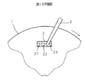
図1は本発明に係る磁気記録媒体及び磁気ヘッドの構成を示す断面図であり、本発明の磁気記録方法の実施態様を示している。図2は図1の平面図である。図中1は本発明に係る磁気ディスクであり、2は本発明に係る磁気ヘッドである。磁気ディスク1は、合成樹脂製の基板11上に前記第2の磁性層たる制御層12、及び前記第1の磁性層たる記録再生層13をDCスパッタ法によりこの順に積層して構成されている。制御層12の保磁力,膜厚,飽和磁化は、夫々、Hc1,t1及びMs1であり、記録再生層13の保磁力,膜厚,飽和磁化は、夫々、Hc2,t2及びMs2である。なお、Hc1<Hc2である。
【0017】
磁気ディスク1上には、記録再生層13に対向して磁気ヘッド2が配されている。磁気ヘッド2はスイングアーム3に連結されており、スイングアーム3の移動により磁気ヘッド2は磁気ディスク1の半径方向に移動可能である。磁気ヘッド2は、その内部に第1,第2及び第3のコイル21,22,23を所定長だけ離隔して設けており、夫々のコイルにより異なる大きさの磁界を磁気ディスク1の対向する領域に印加する。また、磁気ヘッド2は、第1,第2及び第3のコイル21,22,23が並設された方向が、磁気ディスク1のトラックの接線方向になるように対向配置される。ここで、第1,第2及び第3のコイル21,22,23は、夫々、第1の初期化磁界Hdc1,第2の初期化磁界Hdc2,交番磁界Hwを印加する。
【0018】
このような膜構成の磁気ディスク1に情報を記録する際に、磁気ヘッド2を記録再生層13の径方向の所定位置に移動させ、磁気ディスク1を回転させる。磁気ディスク1の回転により、磁気ディスク1は磁気ヘッド2に対して移動している。従って、記録再生層13の記録すべき領域には第1,第2及び第3のコイル21,22,23により、順に磁界が印加される。これらの磁界が印加された時点の制御層12及び記録再生層13の磁化状態について、これらの層の磁化曲線に基づいて以下に説明する。
【0019】
図3は、磁気ディスク1の制御層12及び記録再生層13の磁化曲線を示した図である。図3(a)は記録再生層13単体のヒステリシスループである。図3(b)は制御層12と記録再生層13との交換結合領域のヒステリシスループであり、記録再生層13のマイナーループを太線で示している。いずれの図も縦軸は磁化Mを示し、横軸は磁界Hを示している。制御層12と記録再生層13との交換結合領域は印加される磁界の大きさに応じて、図3(b)に示すように、状態A),状態B),状態C)及び状態D)の磁化状態を示す。図中、白抜き矢印及び二重矢印は、夫々、記録再生層13及び制御層12の相対的な磁化方向を示している。状態A)及び状態C)では同じ方向を向いている。状態B)及び状態D)では相異なる方向を向き、記録再生層13及び制御層12の表面に界面磁壁を形成している。
【0020】
状態A)から状態B)に遷移するための磁界Hab,状態B)から状態C)に遷移するための磁界Hbc,状態C)から状態D)に遷移するための磁界Hcd,及び状態D)から状態A)に遷移するための磁界Hdaは、夫々、
Hab=−Hc1−σ/2Ms1t1
Hbc=−Hc2+σ/2Ms2t2
Hcd=Hc1+σ/2Ms1t1
Hda=Hc2−σ/2Ms2t2
である。ここで、σは界面磁壁のエネルギーである。
【0021】
上述した磁気ディスク1に、まず、第1のコイル21により第1の初期化磁界Hdc1が印加される。ここで|Hdc1|>|Hda|である。このとき、磁界が印加された領域は状態A)、即ち、記録再生層13及び制御層12の磁化が同方向に向いている状態である。所定時間経過後、第2のコイル22により、この領域に第2の初期化磁界Hdc2が印加される。ここで|Hbc|>|Hdc2|>|Hab|である。このとき、磁界が印加された領域は状態B)、即ち、記録再生層13及び制御層12の磁化が逆方向に向いている状態である。
【0022】
さらに所定時間経過後、第3のコイル23により交番磁界Hwが印加される。状態B)から情報が記録された状態に遷移するためには、交番磁界Hwは、|Hba|<|Hw|<|Hab|である。交番磁界Hwは、記録すべき情報に応じた極性が印加される。交番磁界Hwの絶対値の最小値である|Hba|は、|Hba|=|Hc1−σ/2Ms1t1|である。従って、本実施の形態の磁気ディスク1では、記録再生層13単体で記録可能な交番磁界Hc1よりも(σ/2Ms1t1)だけ小さな磁界を用いて、情報を記録することが可能である。
【0023】
以上の如き磁気記録方法により、大きな保磁力の記録再生層13を備える磁気ディスク1に、記録再生層13単体に対して必要な磁界よりも小さな交番磁界の印加で情報を記録することができる。
【0024】
【実施例】
上述の如き特性を有する膜組成の磁気ディスクに、上述の如き記録方法にて情報を記録し、その記録再生特性を調べた。ガラス基板上に、Crからなる第1の下地層(20nm)と、NiAlからなる第2の下地層(20nm)をDCスパッタ法により形成した。スパッタ条件は、投入電力が1kW、Arガス圧が1Paである。その上にDCスパッタ法により、制御層12及び記録再生層13を積層した。制御層12及び記録再生層13の組成、膜厚及びスパッタ条件を表1に示す。
【0025】
【表1】

この磁気ディスクのHab,Hba,Hbcを調べたところ、Hab=−3kOe,Hba=2kOe,Hbc=−4kOeであった。従って、第1の初期化磁界Hdc1,第2の初期化磁界Hdc2、及び交番磁界Hwは、夫々、
Hdc1>4kOe,
−4kOe<Hdc2<−3kOe,
2kOe<Hw<3kOe
である。
【0027】
磁気ディスクの記録領域に、まず第1のコイル21により第1の初期化磁界Hdc1=4.5 kOeを印加することにより状態A)(図3参照)とし、次に第2のコイル22により、第2の初期化磁界Hdc2=−3.4 kOeを印加することにより状態B)(図3参照)とした。交番磁界|Hw|=2.2 kOeを情報に応じて極性を変化させて印加し、0.1ミクロン長の記録マークを形成した。このように情報を記録した磁気ディスクについてSNRを測定したところ、30dB以上の値を示した。これは実用化に充分な値である。
【0028】
次に、比較例として制御層12を設けていない磁気ディスクを作成し、記録再生層13のみの磁気記録特性を調べた。その他の膜構成は上述の実施例と同様である。その結果、記録再生層13に情報を記録するために、2.5 kOe以上の磁界が必要であった。また、高ノイズのために、SNRが5dBと低い値を示した。この結果から判るように、比較例の磁気ディスクでは通常よりも大きな保磁力を有しているので記録のために高い交番磁界が必要となり、且つ、良好な記録特性が得られない。これに対して本実施の形態の磁気ディスクは、大きな保磁力を有する記録再生層に、通常と同じか又は小さい交番磁界を印加することにより情報が記録でき、良好な記録再生特性を有すると言える。
【0029】
【発明の効果】
以上のように、本発明においては、高密度記録を行なうために大きな保磁力を有する磁性層を用いた場合であっても、該磁性層単体に対して必要な記録用磁界の大きさよりも小さな交番磁界で記録を行なうことができ、記録装置に必要以上の負担を与えない等、本発明は優れた効果を奏する。
【図面の簡単な説明】
【図1】本発明に係る磁気記録媒体及び磁気ヘッドの構成を示す断面図である。
【図2】図1の平面図である。
【図3】本実施の形態の磁気ディスクの制御層及び記録再生層の磁化曲線を示した図である。
【符号の説明】
1 磁気ディスク
2 磁気ヘッド
11 基板
12 制御層(第2の磁性層)
13 記録再生層(第1の磁性層)
21 第1のコイル
22 第2のコイル
23 第3のコイル[0001]
BACKGROUND OF THE INVENTION
The present invention relates to a magnetic recording method for recording magnetically information, a magnetic head for applying a magnetic field to 及 beauty magnetic recording medium to record information.
[0002]
[Prior art]
Magnetic disks are widely used as information recording devices in computers. In particular, in a PC (personal computer) environment that handles moving images, there is a demand for a magnetic disk capable of recording a larger capacity, that is, a high-density recording. In order to increase the recording density, the recording mark length formed on the magnetic disk is shortened and the track width is narrowed.
[0003]
For example, information is recorded on a conventional magnetic disk in which a base layer made of Cr and a recording layer made of CoCrTaPt are stacked on a substrate. The coercivity of the recording layer is about 2 kOe. Information can be recorded on the recording layer of this magnetic disk by applying an alternating magnetic field using a normal magnetic head. When a minute recording mark is formed on this recording layer, noise rises due to the particle size of the recording layer. In order to solve this problem, the crystal grain of the recording layer may be made small. However, if the crystal grain is miniaturized, there is a problem that the recorded magnetization direction is likely to be disturbed and the thermal stability of the recording layer is lowered. .
[0004]
[Problems to be solved by the invention]
In order to improve the thermal stability of the recording layer, the coercive force of the recording layer may be increased to, for example, 3 kOe. However, when the coercive force of the magnetic layer is increased, there is a problem that it is necessary to increase the alternating magnetic field applied during recording. When a short recording mark length is formed, there is a problem that application of a large alternating magnetic field places a heavy burden on the recording apparatus because the recording frequency is high.
[0005]
The present invention has been made in view of such circumstances, the magnetic recording medium having a magnetic layer having a large coercive force, realized magnetic recording method capable of recording information by applying a small alternating magnetic field, and the method an object of the present invention is to provide a magnetic head. Hereinafter, the alternating magnetic field in the present application refers to “a magnetic field constituted by the presence or absence of a magnetic field in one direction that causes the recording / reproducing layer to have a magnetization direction corresponding to information to be recorded”.
[0006]
[Means for Solving the Problems]
Magnetic recording method according to the present invention, at least the second magnetic layer and first magnetic layer are laminated in this order, the coercive before Symbol the coercive force Hc1 of the first magnetic layer and the second magnetic layer to the substrate A magnetic recording method for recording information on a magnetic recording medium having a relationship of Hc1 <Hc2 with a magnetic force Hc2 , wherein the magnitudes of magnetizations of the first and second magnetic layers are Ms1, Ms2, each of the film thickness and t1, t2, the Hda the interface wall energy of the first and second magnetic layers upon a σ = Hc2-σ / 2Ms2t2, Hab = -Hc1-σ / 2Ms1t1, Hbc = - Hc For each value defined by 2 + σ / 2Ms2t2, a first initialization magnetic field Hdc1 that satisfies the relationship | Hdc1 |> | Hda | is applied to an area in which information is to be recorded, and the first and second Align the magnetization direction of the magnetic layer in the same direction After the first initialization process and after the first initialization process, a second initialization magnetic field Hdc2 that satisfies the relationship | Hbc |> | Hdc2 |> | Hab | is applied to the region, and the first and second A second initialization process in which the magnetization directions of the magnetic layers are different from each other, and a recording process in which, after the second initialization process, an alternating magnetic field Hw having a polarity changed according to information to be recorded is applied to the area It is characterized by having.
However, | Hc1-σ / 2Ms1t1 | <| Hw | <| Hab |
[0007]
The present invention includes a first magnetic layer for recording and holding information, and a second magnetic layer that can be exchange-coupled to the magnetic layer, and based on the magnetic characteristics in these exchange-coupling regions. By applying the magnetic field having the determined magnitude, the magnetization directions of the first and second magnetic layers are oriented in a predetermined direction immediately before the alternating magnetic field for recording is applied. By applying an alternating magnetic field to the magnetic layer in this state, the magnetization direction of the first magnetic layer can be changed by applying a magnetic field smaller than that of the first magnetic layer alone. After applying the first initialization magnetic field determined based on the magnetic characteristics of the exchange coupling regions of the first and second magnetic layers to align the first and second magnetic layers in the same direction, An initialization magnetic field is applied to reverse the magnetization direction of the first magnetic layer, for example. By applying an alternating magnetic field to the magnetic layer in this state, the magnetization direction of the first magnetic layer can be changed by applying a magnetic field smaller than the required magnitude to the first magnetic layer alone.
[0008]
In the magnetic head according to the present invention, at least the second magnetic layer and the first magnetic layer are stacked in this order on the substrate, and the coercive force Hc1 of the first magnetic layer and the coercive force Hc2 of the second magnetic layer are stacked. Between the magnetic recording medium and the magnetic recording medium having a relationship of Hc1 <Hc2, and applying a magnetic field while moving relative to the magnetic recording medium, a first initialization magnetic field is applied to the magnetic recording medium. A first magnetic generation unit to be applied, a second magnetic generation unit to apply a second initialization magnetic field, and a third magnetic generation unit to apply an alternating magnetic field are arranged in parallel. The direction of installation is arranged substantially parallel to the direction of relative movement, and the first initialization magnetic field applied by the first magnetism generating unit is applied to each of the first and second magnetic layers. The magnitudes of magnetization are Ms1, Ms2, and the respective film thicknesses are t1, t2. For each value defined the interface wall energy of the second magnetic layers upon a sigma by Hda = Hc2-σ / 2Ms2t2, Hab = -Hc1-σ / 2Ms1t1, Hbc = -Hc2 + σ / 2Ms2t2, record information a magnetic field hdc1 that meet the relationships, the second initializing magnetic field second magnetism generating portion is applied, in the region | | hdc1 | |> | Hda to should do region Hbc |> | The magnetic field Hdc2 satisfying the relationship Hdc2 |> | Hab |, and the alternating magnetic field Hw applied by the third magnetism generation unit satisfies | Hc1-σ / 2Ms1t1 | <| Hw | <| Hab |. Features.
[0015]
In the present invention, for example, the first magnetic generation unit that applies the first initialization magnetic field as described above, the second magnetic generation unit that applies the second initialization magnetic field, and the alternating magnetic field are applied. Since the third magnetism generators are arranged in parallel in the relative movement direction, the first initialization magnetic field, the second initialization magnetic field, and the alternating magnetic field are sequentially applied to the same region of the magnetic recording medium that is moving relative to each other. can do.
[0016]
DETAILED DESCRIPTION OF THE INVENTION
Hereinafter, the present invention will be specifically described with reference to the drawings showing embodiments thereof.
FIG. 1 is a cross-sectional view showing the configuration of a magnetic recording medium and a magnetic head according to the present invention, showing an embodiment of the magnetic recording method of the present invention. FIG. 2 is a plan view of FIG. In the figure, 1 is a magnetic disk according to the present invention, and 2 is a magnetic head according to the present invention. The
[0017]
A
[0018]
When recording information on the
[0019]
FIG. 3 is a diagram showing magnetization curves of the
[0020]
From magnetic field Hab for transition from state A) to state B), magnetic field Hbc for transition from state B) to state C), magnetic field Hcd for transition from state C) to state D), and from state D) Magnetic fields Hda for transitioning to state A) are respectively
Hab = −Hc1−σ / 2Ms1t1
Hbc = −Hc2 + σ / 2Ms2t2
Hcd = Hc1 + σ / 2Ms1t1
Hda = Hc2-σ / 2Ms2t2
It is. Here, σ is the energy of the interface domain wall.
[0021]
First, the first initialization magnetic field Hdc1 is applied to the
[0022]
Further, after a predetermined time has elapsed, an alternating magnetic field Hw is applied by the
[0023]
By the magnetic recording method as described above, information can be recorded on the
[0024]
【Example】
Information was recorded on the magnetic disk having a film composition having the above-described characteristics by the recording method as described above, and the recording / reproducing characteristics were examined. A first underlayer (20 nm) made of Cr and a second underlayer (20 nm) made of NiAl were formed on a glass substrate by a DC sputtering method. The sputtering conditions are an input power of 1 kW and an Ar gas pressure of 1 Pa. A
[0025]
[Table 1]
When this magnetic disk was examined for Hab, Hba, and Hbc, it was found that Hab = -3 kOe, Hba = 2 kOe, and Hbc = -4 kOe. Therefore, the first initialization magnetic field Hdc1, the second initialization magnetic field Hdc2, and the alternating magnetic field Hw are respectively
Hdc1> 4 kOe,
−4 kOe <Hdc2 <−3 kOe,
2kOe <Hw <3kOe
It is.
[0027]
First, the first initializing magnetic field Hdc1 = 4.5 kOe is applied to the recording area of the magnetic disk by the
[0028]
Next, a magnetic disk without the
[0029]
【The invention's effect】
As described above, in the present invention, even when a magnetic layer having a large coercive force is used to perform high-density recording, the magnitude of the recording magnetic field required for the magnetic layer alone is smaller. The present invention has an excellent effect that recording can be performed with an alternating magnetic field, and the recording apparatus is not burdened more than necessary.
[Brief description of the drawings]
FIG. 1 is a cross-sectional view showing a configuration of a magnetic recording medium and a magnetic head according to the present invention.
2 is a plan view of FIG. 1. FIG.
FIG. 3 is a diagram showing magnetization curves of a control layer and a recording / reproducing layer of the magnetic disk according to the present embodiment.
[Explanation of symbols]
1
13 Recording / reproducing layer (first magnetic layer)
21
Claims (2)
前記第1及び第2の磁性層の各々の磁化の大きさをMs1、Ms2、各々の膜厚をt1、t2とし、前記第1及び第2の磁性層間の界面磁壁エネルギーをσとした際にHda=Hc2−σ/2Ms2t2、Hab=−Hc1−σ/2Ms1t1、Hbc= - Hc 2 +σ/2Ms2t2によって定義される各値に対して、情報を記録すべき領域に|Hdc1|>|Hda|の関係を満たす第1の初期化磁界Hdc1を印加し、前記第1及び第2の磁性層の磁化方向を同方向に揃える第1初期化過程と、該第1初期化過程後に、前記領域に|Hbc|>|Hdc2|>|Hab|の関係を満たす第2の初期化磁界Hdc2を印加し、前記第1及び第2の磁性層の磁化方向を相異なる方向にする第2初期化過程と、該第2初期化過程後に、記録すべき情報に応じて極性を変化させた交番磁界Hwを前記領域に印加する記録過程とを有することを特徴とする磁気記録方法。
但し、|Hc1−σ/2Ms1t1|<|Hw|<|Hab| At least between the second magnetic layer and first magnetic layer are laminated in this order, before Symbol first coercive force of the coercive force Hc1 of the magnetic layer and the second magnetic layer Hc2 on the substrate, Hc1 < A magnetic recording method for recording information on a magnetic recording medium having a relationship of Hc2 ,
When the magnitudes of the magnetizations of the first and second magnetic layers are Ms1 and Ms2, the film thicknesses are t1 and t2, respectively, and the interface domain wall energy between the first and second magnetic layers is σ. hda = Hc2-σ / 2Ms2t2, Hab = -Hc1-σ / 2Ms1t1, Hbc = - for each value defined by Hc 2 + σ / 2Ms2t2, a region in which information is to be recorded | hdc1 |> | hda | of Applying a first initialization magnetic field Hdc1 that satisfies the relationship, the magnetization directions of the first and second magnetic layers are aligned in the same direction, and after the first initialization process, | Applying a second initialization magnetic field Hdc2 satisfying a relationship of Hbc |> | Hdc2 |> | Hab |, and making the magnetization directions of the first and second magnetic layers different from each other; Should be recorded after the second initialization process Magnetic recording method characterized by comprising a recording step of applying an alternating magnetic field Hw of changing the polarity in response to broadcast to the region.
However, | Hc1-σ / 2Ms1t1 | <| Hw | <| Hab |
第1の初期化磁界を印加する第1の磁気発生部と第2の初期化磁界を印加する第2の磁気発生部と交番磁界を印加する第3の磁気発生部とを並設してあり、前記磁気発生部の並設方向を前記相対移動の方向と略平行に配すべくなしてあり、前記第1の磁気発生部が印加する前記第1の初期化磁界は、前記第1及び第2の磁性層の各々の磁化の大きさをMs1、Ms2、各々の膜厚をt1、t2とし、前記第1及び第2の磁性層間の界面磁壁エネルギーをσとした際にHda=Hc2−σ/2Ms2t2、Hab=−Hc1−σ/2Ms1t1、Hbc=-Hc2+σ/2Ms2t2によって定義される各値に対して、情報を記録すべき領域に|Hdc1|>|Hda|の関係を満たす磁界Hdc1であって、
前記第2の磁気発生部が印加する前記第2の初期化磁界は、
前記領域に|Hbc|>|Hdc2|>|Hab|の関係を満たす磁界Hdc2であって、
前記第3の磁気発生部が印加する交番磁界Hwは、
|Hc1−σ/2Ms1t1|<|Hw|<|Hab|
を満たすことを特徴とする磁気ヘッド。 At least a second magnetic layer and a first magnetic layer are stacked in this order on the substrate, and Hc1 <Hc2 between the coercive force Hc1 of the first magnetic layer and the coercive force Hc2 of the second magnetic layer. In a magnetic head that is arranged to face one surface of a magnetic recording medium having the relationship of and applies a magnetic field while moving relative to the magnetic recording medium,
A first magnetic generation unit that applies a first initialization magnetic field, a second magnetic generation unit that applies a second initialization magnetic field, and a third magnetic generation unit that applies an alternating magnetic field are juxtaposed. The parallel direction of the magnetic generators should be arranged substantially parallel to the direction of relative movement, and the first initialization magnetic field applied by the first magnetic generator is the first and second magnetic fields . When the magnitudes of the magnetizations of the two magnetic layers are Ms1, Ms2, the respective film thicknesses are t1, t2, and the interface domain wall energy between the first and second magnetic layers is σ, Hda = Hc2-σ / 2Ms2t2, Hab = -Hc1-σ / 2Ms1t1, Hbc = -Hc2 + σ / 2Ms2t2 for each value defined by the region in which information is to be recorded | hdc1 |> | Hda | magnetic field satisfying the relationship hdc1 Because
The second initialization magnetic field applied by the second magnetism generator is:
A magnetic field Hdc2 that satisfies the relationship | Hbc |> | Hdc2 |> | Hab |
The alternating magnetic field Hw applied by the third magnetism generator is
| Hc1-σ / 2Ms1t1 | <| Hw | <| Hab |
A magnetic head characterized by satisfying
Priority Applications (1)
| Application Number | Priority Date | Filing Date | Title |
|---|---|---|---|
| JP34683497A JP3856060B2 (en) | 1997-12-16 | 1997-12-16 | Magnetic recording method and magnetic head |
Applications Claiming Priority (1)
| Application Number | Priority Date | Filing Date | Title |
|---|---|---|---|
| JP34683497A JP3856060B2 (en) | 1997-12-16 | 1997-12-16 | Magnetic recording method and magnetic head |
Publications (2)
| Publication Number | Publication Date |
|---|---|
| JPH11185235A JPH11185235A (en) | 1999-07-09 |
| JP3856060B2 true JP3856060B2 (en) | 2006-12-13 |
Family
ID=18386131
Family Applications (1)
| Application Number | Title | Priority Date | Filing Date |
|---|---|---|---|
| JP34683497A Expired - Fee Related JP3856060B2 (en) | 1997-12-16 | 1997-12-16 | Magnetic recording method and magnetic head |
Country Status (1)
| Country | Link |
|---|---|
| JP (1) | JP3856060B2 (en) |
-
1997
- 1997-12-16 JP JP34683497A patent/JP3856060B2/en not_active Expired - Fee Related
Also Published As
| Publication number | Publication date |
|---|---|
| JPH11185235A (en) | 1999-07-09 |
Similar Documents
| Publication | Publication Date | Title |
|---|---|---|
| WO1998003972A1 (en) | Master information carrier, process for producing the carrier, and method and apparatus for recording master information signal on magnetic recording medium by using the carrier | |
| JPH0997419A (en) | Magnetic disk, production of magnetic disk and magnetic recorder | |
| JP3350512B2 (en) | Perpendicular magnetic recording medium and magnetic recording / reproducing device | |
| JPH0845029A (en) | Thin-film magnetic head | |
| JP2004118894A (en) | Disk-like magnetic recording medium | |
| KR20020013577A (en) | Spin bulb magnetoresistance effect head and compound magnetic head and compound magnetic head using it and magnetic recording medium drive unit | |
| JP2002216333A (en) | Magnetic recording medium and magnetic recording machine | |
| JP3856060B2 (en) | Magnetic recording method and magnetic head | |
| JP4263802B2 (en) | Magnetic core, magnetic sensor, and magnetic recording head | |
| JP3175922B2 (en) | Method of manufacturing spin-valve thin film element | |
| JP2989575B2 (en) | Magneto-optical recording medium | |
| JPWO2004019322A1 (en) | Backed magnetic film | |
| JP2003203322A (en) | Information recording medium and information storage device | |
| JPH10340431A (en) | Magneto-resistance effect type head and magnetic recording/reproducing device | |
| JP3930281B2 (en) | Method for reducing noise in a perpendicular magnetic recording / reproducing apparatus | |
| JPS6029927A (en) | Vertical magnetic recording medium | |
| JP3911678B2 (en) | Multilayer perpendicular magnetic recording medium | |
| JP3617400B2 (en) | Method for manufacturing perpendicular magnetic recording medium | |
| JPH0714710A (en) | Magnetoresistive effect element | |
| JPH0224815A (en) | Magnetic recording medium | |
| JPH11284248A (en) | Magnetoresistance effect element | |
| JP4694536B2 (en) | Magnetic recording medium, method for manufacturing magnetic recording medium, and magnetic information recording method | |
| JPS63237204A (en) | Magneto-resistance effect head | |
| JPH0559484B2 (en) | ||
| JP2000187814A (en) | Composite magnetic head and its production |
Legal Events
| Date | Code | Title | Description |
|---|---|---|---|
| A02 | Decision of refusal |
Free format text: JAPANESE INTERMEDIATE CODE: A02 Effective date: 20040113 |
|
| A521 | Written amendment |
Free format text: JAPANESE INTERMEDIATE CODE: A523 Effective date: 20040303 |
|
| A911 | Transfer of reconsideration by examiner before appeal (zenchi) |
Free format text: JAPANESE INTERMEDIATE CODE: A911 Effective date: 20040407 |
|
| A912 | Removal of reconsideration by examiner before appeal (zenchi) |
Free format text: JAPANESE INTERMEDIATE CODE: A912 Effective date: 20040507 |
|
| A61 | First payment of annual fees (during grant procedure) |
Free format text: JAPANESE INTERMEDIATE CODE: A61 Effective date: 20060905 |
|
| R150 | Certificate of patent or registration of utility model |
Free format text: JAPANESE INTERMEDIATE CODE: R150 |
|
| FPAY | Renewal fee payment (event date is renewal date of database) |
Free format text: PAYMENT UNTIL: 20090922 Year of fee payment: 3 |
|
| FPAY | Renewal fee payment (event date is renewal date of database) |
Free format text: PAYMENT UNTIL: 20100922 Year of fee payment: 4 |
|
| LAPS | Cancellation because of no payment of annual fees |