JP3854094B2 - Remote control lock device for vehicle - Google Patents
Remote control lock device for vehicle Download PDFInfo
- Publication number
- JP3854094B2 JP3854094B2 JP2001160048A JP2001160048A JP3854094B2 JP 3854094 B2 JP3854094 B2 JP 3854094B2 JP 2001160048 A JP2001160048 A JP 2001160048A JP 2001160048 A JP2001160048 A JP 2001160048A JP 3854094 B2 JP3854094 B2 JP 3854094B2
- Authority
- JP
- Japan
- Prior art keywords
- code
- lock device
- remote control
- lock
- vehicle
- Prior art date
- Legal status (The legal status is an assumption and is not a legal conclusion. Google has not performed a legal analysis and makes no representation as to the accuracy of the status listed.)
- Expired - Fee Related
Links
Images


Description
【0001】
【発明の属する技術分野】
本発明は、車両のハンドルロック装置を作動および作動解除するアクチュエータをリモコン送信機で制御するロック制御手段を備え、ハンドルロック装置の作動中にロック制御手段に待機電流を間欠的に供給して電力の節減を図る車両のリモコンロック装置に関する。
【0002】
【従来の技術】
車両外部のリモコン送信機を操作することでドアロック装置を作動および作動解除するリモコンロック装置は、四輪車において周知である。かかるリモコンロック装置では、リモコン送信機から送信されたIDコードをロック制御手段で受信して予め記憶したIDコードと比較し、両者が一致した場合にドアロック装置を作動解除して車両の盗難や不正使用を防止するようになっており、そのために乗員が車両を離れている間にロック制御手段に常に待機電流を流しておく必要がある。しかしながら、長期に亘ってロック制御手段に待機電流を流しておくとバッテリの負担が大きくなるため、ロック制御手段に待機電流を間欠的に供給することで電力の節減を図っている。例えば、ロック制御手段のIDコード取得手段を間欠駆動することで待機電流を1.5mA程度に抑えることができ、IDコード取得手段およびIDコード照合手段の両方を間欠駆動することで待機電流を1.0mA程度に抑えることができる。
【0003】
【発明が解決しようとする課題】
ところで、自動二輪車や自動三輪車のような小型車両のハンドルロック装置に上記四輪車のリモコンロック装置を適用した場合、小型車両のバッテリは容量が小さいことから、待機電流を間欠的に供給する手法で電力の節減を図ってもバッテリあがりを起こす可能性がある。これを防止するには、待機電流の間欠供給レシオ(全時間に対する待機電流が供給される時間の比)を小さくすることが考えられるが、このようにすると待機電流が流れる時間間隔が大きくなるため、リモコン送信機を操作してからハンドルロック装置が作動するまでの応答性が低下する問題がある。また別の手法として、車両が一定時間使用されずに放置された場合にロック制御手段に対する待機電流の供給を遮断することが考えられるが、このようにすると、次に車両を使用するときにリモコン送信機でハンドルロック装置を作動させることができないのは勿論のこと、起動スイッチ等を用いてロック制御手段を再起動させる操作が必要になる問題がある。
【0004】
本発明は前述の事情に鑑みてなされたもので、リモコンロック装置の応答性を最大限に確保しながら、待機電流を最小限に抑えてバッテリの消耗を防止することを目的とする。
【課題を解決するための手段】
上記目的を達成するために、請求項1に記載された発明によれば、車両のハンドルロック装置を作動および作動解除するアクチュエータをリモコン送信機で制御するロック制御手段を備え、ハンドルロック装置の作動中にロック制御手段に待機電流を間欠的に供給して電力の節減を図る車両のリモコンロック装置において、ロック制御手段は、リコモン送信機から送信されるIDコードを受信するIDコード取得手段と、前記取得したIDコードを予め記憶したIDコードと比較するIDコード照合手段とを備え、ロック制御手段の待機時間が短い通常モードではIDコード取得手段を間欠駆動してIDコード照合手段を連続駆動し、ロック制御手段の待機時間が長い長期放置モードではIDコード取得手段およびIDコード照合手段の両方を間欠駆動することを特徴とする車両のリモコンロック装置が提案される。上記構成によれば、ロック制御手段の待機時間が短い通常モードではIDコード取得手段だけを間欠駆動しIDコード照合手段を連続駆動し、ロック制御手段の待機時間が長い長期放置モードではIDコード取得手段およびIDコード照合手段の両方を間欠駆動するので、電力の節減が特に必要となる待機時間が長い長期放置モードにおいて、電力の効果的な節減を可能とすることができる。
【0005】
また請求項2に記載された発明によれば、請求項1の構成に加えて、前記待機電流の間欠供給レシオを異ならせた複数のモードを選択可能にし、ロック制御手段の待機時間が短いモードほど間欠供給レシオを大きくし、ロック制御手段の待機時間が長いモードほど間欠供給レシオを小さくし、前記複数のモードには、前記通常モード及び前記長期放置モードが含まれることを特徴とする車両のリモコンロック装置が提案される。
【0006】
上記構成によれば、ハンドルロック装置の作動中にロック制御手段に待機電流を間欠的に供給して電力の節減を図る際に、電力の節減がさほど必要でない待機時間が短いモード、例えば通常モードでは、間欠供給レシオを大きくしてハンドルロック装置の作動解除の応答性を高めることができ、また電力の節減が特に必要となる待機時間が長いモード、例えば長期放置モードでは、間欠供給レシオを小さくして電力の効果的な節減を可能とすることができ、これによりハンドルロック装置の作動解除の応答性および電力の節減を両立させることが可能になる。また待機時間が長い場合にもロック制御手段への電流供給が完全に遮断されることがないため、ロック制御手段を再起動するための特別の操作が不要になる。
【0007】
また請求項3に記載された発明によれば、請求項1又は2の構成に加えて、前記通常モードの状態であることの判断のためのインジケータを備えたことを特徴とする。
【0008】
【発明の実施の形態】
以下、本発明の実施形態を、添付図面に示した本発明の実施例に基づいて説明する。
【0009】
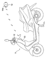
図1〜図4は本発明の第1実施例を示すもので、図1はリモコンロック装置を備えた自動二輪車の全体側面図、図2はリモコンロック装置のブロック図、図3は通常モードの作用を説明するタイムチャート、図4は長期放置モードの作用を説明するタイムチャートである。
【0010】
図1に示すように、スクータ型の自動二輪車Vのレッグシールド11の上部に、ステアリングハンドル12の回動をロックあるいはアンロックするリモコンロック装置13が設けられる。リモコンロック装置13は、乗員が手に持って操作するリモコン送信機14から送信される電波で作動する。
【0011】
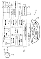
図2に示すように、リモコンロック装置13にはロック制御手段15を備えており、ロック制御手段15にはIDコード取得手段16と、IDコード照合手段17と、間欠駆動回路18と、電源回路19と、電源スイッチング回路20と、メインリレー駆動手段21と、アクチュエータ駆動手段22と、インジケータ出力手段23とが含まれる。
【0012】
メインリレー駆動手段21は、車載のバッテリ24を種々の電装品負荷25に接続するメインリレー26に接続され、アクチュエータ駆動手段22は、自動二輪車Vのステアリングハンドル12を回動不能にロックするハンドルロック装置27のアクチュエータ28に接続される。また手動でメインスイッチ29を開閉すれば、ロック制御手段15を介さずにメインリレー26およびハンドルロック装置27を操作することができる。更にインジケータ出力手段23は、メータパネル30に設けられたインジケータ31の点灯・消灯を制御する。
【0013】
ロック制御手段15は待機電流の消費量が異なる通常モードおよび長期放置モードを切り換え可能であり、乗員が車両を離れるべくメインスイッチ29をオフするとロック制御手段15は通常モードになり、通常モードが予め設定した時間継続すると長期放置モードに切り換わる。
【0014】
図3および図4を併せて参照すると明らかなように、IDコード取得手段16およびIDコード照合手段17には、車載のバッテリ24から電源回路19および電源スイッチング回路20を介して電流が供給される。このときIDコード照合手段17の内部に備えられたタイマ、あるいは間欠駆動回路18のタイマが所定時間毎にパルス信号を出力し、それらのパルス信号に基づいてIDコード取得手段16およびIDコード照合手段17への待機電流の供給が制御される。
【0015】
図3に示す通常モードでは、IDコード照合手段17に連続的に電流が供給され、IDコード取得手段16にはIDコード照合手段17の内部に備えられたタイマからのパルス信号に基づいて間欠的に電流が供給される。このときの間欠供給レシオ(全時間に対する電流が供給される時間の比)は比較的に大きい3.3%〜20%程度であり、これによりロック制御手段15の待機電流は1.5mA〜3.0mA程度となる。この通常モードでは、メータパネル30に設けられたインジケータ31は点滅する。
【0016】
また図4に示す長期放置モードでは、間欠駆動回路18のタイマが出力するパルス信号に基づいて、IDコード照合手段17およびIDコード取得手段16の両方に間欠的に電流が供給される。このときの間欠供給レシオ(全時間に対する電流が供給される時間の比)は比較的に小さい0.5%程度であり、これによりロック制御手段15の待機電流は100μA〜500μAとなる。この長期放置モードでは、メータパネル30に設けられたインジケータ31は消灯する。
【0017】
リモコン送信機14のロック・アンロックボタン14aを押して離すと起動コード信号およびIDコード信号が送信される。ロック・アンロックボタン14aを短い時間(例えば、0.5sec未満)押すと、起動コード信号が短い時間(例えば、50〜300msec)送信され(図3参照)、ロック・アンロックボタン14aを長い時間(例えば、0.5sec以上)押すと、起動コード信号が長い時間(例えば、300〜1000msec)送信される(図4参照)。
【0018】
次に、上記構成を備えた本発明の実施例の作用を説明する。
【0019】
停車中の車両を走行させるべくハンドルロック装置27の作動を解除するには、先ずメータパネル30に設けられたインジケータ31の状態を確認し、インジケータ31が点滅していればロック制御手段15が通常モードの状態にあると判断し、図3に示すようにリモコン送信機14のロック・アンロックボタン14aを短時間(0.5sec未満)だけ押す。ロック・アンロックボタン14aを離した瞬間にリモコン送信機14は起動コード信号およびIDコード信号を出力するが、通常モードにおける起動コード信号の出力時間Aは比較的に短い50〜300msecとされる。そして前記起動コード信号の出力時間AはIDコード取得手段16に電流が間欠的に供給される周期Aに一致しているため、起動コード信号が出力されている間に必ずIDコード取得手段16に電流が供給されている状態があり、その間に確実に起動コード信号が受信される。
【0020】
起動コード信号が受信されると、それまで間欠的に電流が供給されていたIDコード取得手段16に連続的に電流が供給されるようになるため、リモコン送信機14が起動コード信号に続いて送信したIDコード信号がIDコード取得手段16に確実に受信される。このようにしてIDコード取得手段16が取得したIDコードは、IDコード照合手段17において予め記憶されていたIDコードと比較され、両者が一致するとアクチュエータ駆動手段22が作動してハンドルロック装置27の作動を解除するとともに、メインリレー駆動手段21がメインリレー26を閉成して電装品負荷25にバッテリ24から電力を供給する。この通常モードでは、ロック・アンロックボタン14aを押してからハンドルロック装置27の作動が解除するまでの時間は比較的に短いCとなる。
【0021】
一方、メータパネル30に設けられたインジケータ31が消灯していればロック制御手段15が長期放置モードの状態にあると判断し、図4に示すようにリモコン送信機14のロック・アンロックボタン14aを長時間(0.5sec以上)押す。ロック・アンロックボタン14aを離した瞬間にリモコン送信機14は起動コード信号およびIDコード信号を出力するが、長期放置モードにおける起動コード信号の出力時間Bは比較的に長い300〜1000msecとされる。そして前記起動コード信号の出力時間Bは間欠駆動回路18のタイマが出力するパルス信号の周期、つまりIDコード取得手段16およびIDコード照合手段17に電流が間欠的に供給される周期Bに一致しているため、起動コード信号が出力されている間に必ずIDコード取得手段16に電流が供給されている状態があり、その間に確実に起動コード信号が受信される。
【0022】
起動コード信号が受信されると、それまで間欠的に電流が供給されていたIDコード取得手段16およびIDコード照合手段17に連続的に電流が供給されるようになるため、リモコン送信機14が起動コード信号に続いて送信したIDコード信号がIDコード取得手段16に確実に受信され、かつIDコード照合手段17においてIDコードの照合が行われる。そして取得したIDコードと予め記憶されていたIDコードとが一致するとアクチュエータ駆動手段22が作動してハンドルロック装置27の作動を解除するとともに、メインリレー駆動手段21がメインリレー26を閉成して電装品負荷25にバッテリ24から電力を供給する。この長期放置モードでは、ロック・アンロックボタン14aを押してからハンドルロック装置27の作動が解除するまでの時間は比較的に長いDとなる。
【0023】
上述のようにして起動コードが受信されると、IDコード取得手段16およびIDコード照合手段17が連続的に駆動されるため(通常モードでは、IDコード照合手段17は連続的に駆動されている)、次に乗員が車両を離れる際に、リモコン送信機14のロック・アンロックボタン14aを押してハンドルロック装置27を支障なく作動させることができる。尚、ハンドルロック装置27の作動が解除された状態では、車両が走行してバッテリ24が充電されるため、IDコード取得手段16およびIDコード照合手段17を連続的に駆動しても何ら問題はない。
【0024】
以上のように、ハンドルロック装置27が作動した直後は通常モードが選択され、IDコード取得手段16に比較的に大きい間欠供給レシオで(つまり比較的に短い時間間隔で)待機電流が供給されるので、ある程度の節電効果を発揮させながら、比較的に短い時間C(図3参照)でハンドルロック装置27の作動を解除して応答性を確保することができる。一方、ハンドルロック装置27が作動してから所定時間が経過すると長期放置モードが選択され、IDコード取得手段16およびIDコード照合手段17の両方に比較的に小さい間欠供給レシオで(つまり比較的に長い時間間隔で)待機電流が供給されるので、大きな節電効果を発揮させることができる。但し、この場合にはハンドルロック装置27の作動を解除するのに、比較的に長い時間D(図4参照)が必要になって応答性が若干低下する。
【0025】
以上、本発明の実施例を詳述したが、本発明はその要旨を逸脱することなく種々の設計変更を行うことが可能である。
【0026】
例えば、図5に示す第2実施例の如く、リモコン送信機14に長期放置モード用のアンロックボタン14bを設け、このアンロックボタン14bを瞬間的に押すことで、起動コード信号およびIDコード信号を出力可能にすれば、ロック・アンロックボタン14aを長押しする必要がなくなって操作性が向上する。
【0027】
また実施例では、待機時間の間欠供給レシオの選択に当たり、通常モードと長期放置モードの2種類のモードを設定しているが、3種類以上のモードを設定することも可能である。
【0028】
【発明の効果】
以上のように本発明によれば、ロック制御手段の待機時間が短い通常モードではIDコード取得手段だけを間欠駆動してIDコード照合手段を連続駆動し、ロック制御手段の待機時間が長い長期放置モードではIDコード取得手段およびIDコード照合手段の両方を間欠駆動するので、電力の節減が特に必要となる待機時間が長い長期放置モードにおいて、電力の効果的な節減を可能とすることができる。
【0029】
また特に請求項2の発明によれば、ハンドルロック装置の作動中にロック制御手段に待機電流を間欠的に供給して電力の節減を図る際に、電力の節減がさほど必要でない待機時間が短いモード、例えば通常モードでは、間欠供給レシオを大きくしてハンドルロック装置の作動解除の応答性を高めることができ、また電力の節減が特に必要となる待機時間が長いモード、例えば長期放置モードでは、間欠供給レシオを小さくして電力の効果的な節減を可能とすることができ、これによりハンドルロック装置の作動解除の応答性および電力の節減を両立させることが可能になる。また待機時間が長い場合にもロック制御手段への電流供給が完全に遮断されることがないため、ロック制御手段を再起動するための特別の操作が不要になる。
【図面の簡単な説明】
【図1】 リモコンロック装置を備えた自動二輪車の全体側面図
【図2】 リモコンロック装置のブロック図
【図3】 通常モードの作用を説明するタイムチャート
【図4】 長期放置モードの作用を説明するタイムチャート
【図5】 本発明の第2実施例に係るリモコン送信機の正面図
【符号の説明】
14 リモコン送信機
15 ロック制御手段
16 IDコード取得手段
17 IDコード照合手段
27 ハンドルロック装置
28 アクチュエータ[0001]
BACKGROUND OF THE INVENTION
The present invention comprises a lock control means for controlling an actuator for operating and releasing a vehicle handle lock device with a remote control transmitter, and intermittently supplies a standby current to the lock control means during operation of the handle lock device. The present invention relates to a remote control lock device for a vehicle for saving energy.
[0002]
[Prior art]
A remote control lock device that activates and deactivates a door lock device by operating a remote control transmitter outside the vehicle is well known in four-wheeled vehicles. In such a remote control lock device, the ID code transmitted from the remote control transmitter is received by the lock control means and compared with the ID code stored in advance, and when the two match, the door lock device is deactivated and the vehicle is stolen. In order to prevent unauthorized use, it is necessary to always allow a standby current to flow through the lock control means while the occupant leaves the vehicle. However, if a standby current is allowed to flow through the lock control unit for a long period of time, the burden on the battery increases. Therefore, power is saved by intermittently supplying the standby current to the lock control unit. For example, the standby current can be suppressed to about 1.5 mA by intermittently driving the ID code acquisition unit of the lock control unit, and the standby current can be reduced to 1 by intermittently driving both the ID code acquisition unit and the ID code verification unit. It can be suppressed to about 0.0 mA.
[0003]
[Problems to be solved by the invention]
By the way, when the above-mentioned four-wheeled vehicle remote control lock device is applied to a handle lock device of a small vehicle such as a motorcycle or a three-wheeled vehicle, the battery of the small vehicle has a small capacity, so that a standby current is intermittently supplied. Even if power saving is attempted, there is a possibility that the battery will rise. In order to prevent this, it is conceivable to reduce the intermittent supply ratio of standby current (ratio of the time during which standby current is supplied to the total time), but this increases the time interval during which standby current flows. There is a problem that the response from the operation of the remote control transmitter to the operation of the handle lock device is lowered. As another method, when the vehicle is left unused for a certain period of time, it may be considered to cut off the supply of standby current to the lock control means. In this way, the remote controller is used the next time the vehicle is used. As a matter of course, the handle lock device cannot be operated by the transmitter, and there is a problem that an operation for restarting the lock control means using an activation switch or the like is required.
[0004]
The present invention has been made in view of the above circumstances, and an object of the present invention is to prevent battery consumption by minimizing standby current while ensuring the responsiveness of a remote control lock device to the maximum.
[Means for Solving the Problems]
In order to achieve the above object, according to the first aspect of the present invention, there is provided lock control means for controlling an actuator for operating and deactivating the vehicle handle lock device with a remote control transmitter, and the operation of the handle lock device is provided. In a remote control lock device for a vehicle that saves power by intermittently supplying standby current to the lock control means , the lock control means includes an ID code acquisition means for receiving an ID code transmitted from a recommon transmitter, An ID code verification unit that compares the acquired ID code with a pre-stored ID code, and in a normal mode in which the lock control unit has a short standby time, the ID code acquisition unit is intermittently driven to continuously drive the ID code verification unit. , Both the ID code acquisition means and the ID code verification means in the long-term neglect mode where the waiting time of the lock control means is long Remote lock apparatus for a vehicle, characterized in that the intermittent driving is proposed. According to the above configuration, in the normal mode where the waiting time of the lock control means is short, only the ID code obtaining means is intermittently driven and the ID code collating means is continuously driven, and in the long-term leaving mode where the waiting time of the lock control means is long, the ID code is obtained Since both the means and the ID code collating means are intermittently driven, it is possible to effectively reduce the power in the long-term leaving mode in which the power saving is particularly required and the standby time is long.
[0005]
According to the second aspect of the present invention, in addition to the configuration of the first aspect, a plurality of modes having different standby current intermittent supply ratios can be selected, and the standby time of the lock control means is short. The intermittent supply ratio is increased as the standby time of the lock control means is longer, and the intermittent supply ratio is decreased as the mode is longer. The plurality of modes include the normal mode and the long-term neglect mode . A remote control lock device is proposed.
[0006]
According to the above configuration, when the standby current is intermittently supplied to the lock control means during operation of the handle lock device to save power, a mode in which the standby time in which the power saving is not so necessary is short , for example, the normal mode In this mode , the intermittent supply ratio can be increased to improve the responsiveness of releasing the operation of the handle lock device, and the intermittent supply ratio can be reduced in the long standby time mode in which power saving is particularly necessary , for example, in the long-term leaving mode. Thus, it is possible to effectively reduce the electric power, thereby making it possible to achieve both the response of releasing the operation of the handle lock device and the electric power. Further, even when the standby time is long, the current supply to the lock control means is not completely cut off, so that a special operation for restarting the lock control means becomes unnecessary.
[0007]
According to a third aspect of the invention, in addition to the configuration of the first or second aspect, an indicator for determining that the state is in the normal mode is provided.
[0008]
DETAILED DESCRIPTION OF THE INVENTION
Embodiments of the present invention will be described below based on the embodiments of the present invention shown in the accompanying drawings.
[0009]
1 to 4 show a first embodiment of the present invention. FIG. 1 is an overall side view of a motorcycle equipped with a remote control lock device, FIG. 2 is a block diagram of the remote control lock device, and FIG. FIG. 4 is a time chart for explaining the operation of the long-term leaving mode.
[0010]
As shown in FIG. 1, a remote
[0011]
As shown in FIG. 2, the remote
[0012]
The main relay driving means 21 is connected to a
[0013]
The lock control means 15 can switch between a normal mode and a long-term leaving mode in which standby current consumption is different. When the occupant turns off the
[0014]
As is apparent when referring to FIGS. 3 and 4, current is supplied to the ID
[0015]
In the normal mode shown in FIG. 3, current is continuously supplied to the ID
[0016]
Further, in the long-term leaving mode shown in FIG. 4, current is intermittently supplied to both the ID
[0017]
When the lock /
[0018]
Next, the operation of the embodiment of the present invention having the above configuration will be described.
[0019]
In order to release the operation of the
[0020]
When the activation code signal is received, since the current is continuously supplied to the ID
[0021]
On the other hand, if the
[0022]
When the activation code signal is received, since the current is continuously supplied to the ID
[0023]
When the activation code is received as described above, the ID
[0024]
As described above, immediately after the
[0025]
As mentioned above, although the Example of this invention was explained in full detail, this invention can perform a various design change, without deviating from the summary.
[0026]
For example, as in the second embodiment shown in FIG. 5, the
[0027]
In the embodiment , when selecting the intermittent supply ratio of the standby time, two types of modes , the normal mode and the long-term leaving mode, are set. However, three or more modes can be set.
[0028]
【The invention's effect】
As described above, according to the present invention, in the normal mode in which the waiting time of the lock control means is short, only the ID code obtaining means is intermittently driven to continuously drive the ID code checking means, and the lock control means is left standing for a long time. Since both the ID code acquisition means and the ID code verification means are intermittently driven in the mode, it is possible to effectively save the power in the long-term leaving mode in which the power saving is particularly required.
[0029]
In particular, according to the invention of claim 2, when the standby current is intermittently supplied to the lock control means during the operation of the handle lock device to reduce the power consumption, the standby time that does not require much power saving is short. mode, for example, in the normal mode, the intermittent supply ratio was significantly can increase the responsiveness of the deactivation of the steering lock device, also power-latency mode savings is particularly required, for example, long-standing mode, It is possible to reduce the intermittent supply ratio and to effectively reduce the power, thereby making it possible to achieve both the responsiveness of releasing the operation of the handle lock device and the power saving. Further, even when the standby time is long, the current supply to the lock control means is not completely cut off, so that a special operation for restarting the lock control means becomes unnecessary.
[Brief description of the drawings]
FIG. 1 is an overall side view of a motorcycle equipped with a remote control lock device. FIG. 2 is a block diagram of the remote control lock device. FIG. 3 is a time chart explaining the operation of a normal mode. [FIG. 5] Front view of a remote control transmitter according to the second embodiment of the present invention [Explanation of symbols]
14
Claims (3)
ロック制御手段(15)は、リコモン送信機(14)から送信されるIDコードを受信するIDコード取得手段(16)と、前記取得したIDコードを予め記憶したIDコードと比較するIDコード照合手段(17)とを備え、
ロック制御手段(15)の待機時間が短い通常モードではIDコード取得手段(16)を間欠駆動してIDコード照合手段(17)を連続駆動し、ロック制御手段(15)の待機時間が長い長期放置モードではIDコード取得手段(16)およびIDコード照合手段(17)の両方を間欠駆動することを特徴とする、車両のリモコンロック装置。A lock control means (15) for controlling an actuator (28) for operating and deactivating the vehicle handle lock device (27) with a remote control transmitter (14) is provided. In a remote control lock device for a vehicle that saves power by intermittently supplying standby current to (15),
The lock control means (15) includes an ID code acquisition means (16) for receiving an ID code transmitted from the recommon transmitter (14), and an ID code verification means for comparing the acquired ID code with an ID code stored in advance. (17)
In the normal mode in which the waiting time of the lock control means (15) is short, the ID code acquisition means (16) is intermittently driven and the ID code collating means (17) is continuously driven, and the waiting time of the lock control means (15) is long. A remote control lock device for a vehicle, characterized in that both the ID code acquisition means (16) and the ID code verification means (17) are intermittently driven in the idle mode.
Priority Applications (4)
| Application Number | Priority Date | Filing Date | Title |
|---|---|---|---|
| JP2001160048A JP3854094B2 (en) | 2001-05-29 | 2001-05-29 | Remote control lock device for vehicle |
| US10/131,023 US6734578B2 (en) | 2001-05-29 | 2002-04-25 | Vehicular remote control lock apparatus |
| DE2002600813 DE60200813T2 (en) | 2001-05-29 | 2002-05-17 | Remote locking device for vehicles |
| EP20020011070 EP1262925B1 (en) | 2001-05-29 | 2002-05-17 | Vehicular remote control lock apparatus |
Applications Claiming Priority (1)
| Application Number | Priority Date | Filing Date | Title |
|---|---|---|---|
| JP2001160048A JP3854094B2 (en) | 2001-05-29 | 2001-05-29 | Remote control lock device for vehicle |
Publications (2)
| Publication Number | Publication Date |
|---|---|
| JP2002347577A JP2002347577A (en) | 2002-12-04 |
| JP3854094B2 true JP3854094B2 (en) | 2006-12-06 |
Family
ID=19003527
Family Applications (1)
| Application Number | Title | Priority Date | Filing Date |
|---|---|---|---|
| JP2001160048A Expired - Fee Related JP3854094B2 (en) | 2001-05-29 | 2001-05-29 | Remote control lock device for vehicle |
Country Status (1)
| Country | Link |
|---|---|
| JP (1) | JP3854094B2 (en) |
Families Citing this family (1)
| Publication number | Priority date | Publication date | Assignee | Title |
|---|---|---|---|---|
| JP4523584B2 (en) * | 2006-12-28 | 2010-08-11 | 本田技研工業株式会社 | Motorcycle handle lock device |
-
2001
- 2001-05-29 JP JP2001160048A patent/JP3854094B2/en not_active Expired - Fee Related
Also Published As
| Publication number | Publication date |
|---|---|
| JP2002347577A (en) | 2002-12-04 |
Similar Documents
| Publication | Publication Date | Title |
|---|---|---|
| US6734578B2 (en) | Vehicular remote control lock apparatus | |
| EP2072354A1 (en) | Keyless alert system and method of automobiles | |
| CN109606338A (en) | A kind of electronic brake system and the method for waking up the system under suspend mode | |
| JP2002539652A5 (en) | ||
| JP2000515955A (en) | Actuator of control device in automobile | |
| US9963039B1 (en) | Method and system for controlling lock of charging inlet | |
| JP3854094B2 (en) | Remote control lock device for vehicle | |
| JP5294078B2 (en) | Power control device | |
| CN113547925B (en) | Control system and electric automobile | |
| US7456730B2 (en) | Anomaly judgment system for operator detection device and process for judging normality/anomaly of operator detection device | |
| CN110603172A (en) | On-board system for a motor vehicle for powering and controlling the lights of a trailer | |
| JP3923277B2 (en) | Remote control lock device for vehicle | |
| KR200255066Y1 (en) | Using of minute ampere to burglar alarm | |
| JPH0744211A (en) | Power consumption controller for vehicle | |
| JP2000344054A (en) | Antitheft device for vehicle | |
| CN205075763U (en) | Automatic skylight device that closes of lock car | |
| CN115520307A (en) | Control system of electric motorcycle | |
| JP3220494B2 (en) | Ventilation control device for vehicles | |
| JP2964346B2 (en) | Car door unlocking device | |
| JPH0744209A (en) | Power consumption controller for vehicle | |
| CN110843528A (en) | Automatic on-off control system for low-voltage auxiliary power supply of pure electric vehicle | |
| JPH0428835Y2 (en) | ||
| KR19980031453A (en) | Window automatic closing device | |
| CN113022761A (en) | Method and device for powering on and powering off electric motorcycle | |
| KR970008544B1 (en) | Room lamp control device for a car |
Legal Events
| Date | Code | Title | Description |
|---|---|---|---|
| A621 | Written request for application examination |
Free format text: JAPANESE INTERMEDIATE CODE: A621 Effective date: 20041203 |
|
| A977 | Report on retrieval |
Free format text: JAPANESE INTERMEDIATE CODE: A971007 Effective date: 20060323 |
|
| A131 | Notification of reasons for refusal |
Free format text: JAPANESE INTERMEDIATE CODE: A131 Effective date: 20060329 |
|
| A521 | Written amendment |
Free format text: JAPANESE INTERMEDIATE CODE: A523 Effective date: 20060529 |
|
| A131 | Notification of reasons for refusal |
Free format text: JAPANESE INTERMEDIATE CODE: A131 Effective date: 20060614 |
|
| A521 | Written amendment |
Free format text: JAPANESE INTERMEDIATE CODE: A523 Effective date: 20060807 |
|
| TRDD | Decision of grant or rejection written | ||
| A01 | Written decision to grant a patent or to grant a registration (utility model) |
Free format text: JAPANESE INTERMEDIATE CODE: A01 Effective date: 20060823 |
|
| A61 | First payment of annual fees (during grant procedure) |
Free format text: JAPANESE INTERMEDIATE CODE: A61 Effective date: 20060907 |
|
| R150 | Certificate of patent or registration of utility model |
Free format text: JAPANESE INTERMEDIATE CODE: R150 |
|
| FPAY | Renewal fee payment (event date is renewal date of database) |
Free format text: PAYMENT UNTIL: 20100915 Year of fee payment: 4 |
|
| FPAY | Renewal fee payment (event date is renewal date of database) |
Free format text: PAYMENT UNTIL: 20100915 Year of fee payment: 4 |
|
| FPAY | Renewal fee payment (event date is renewal date of database) |
Free format text: PAYMENT UNTIL: 20110915 Year of fee payment: 5 |
|
| FPAY | Renewal fee payment (event date is renewal date of database) |
Free format text: PAYMENT UNTIL: 20110915 Year of fee payment: 5 |
|
| FPAY | Renewal fee payment (event date is renewal date of database) |
Free format text: PAYMENT UNTIL: 20120915 Year of fee payment: 6 |
|
| FPAY | Renewal fee payment (event date is renewal date of database) |
Free format text: PAYMENT UNTIL: 20120915 Year of fee payment: 6 |
|
| FPAY | Renewal fee payment (event date is renewal date of database) |
Free format text: PAYMENT UNTIL: 20130915 Year of fee payment: 7 |
|
| FPAY | Renewal fee payment (event date is renewal date of database) |
Free format text: PAYMENT UNTIL: 20140915 Year of fee payment: 8 |
|
| LAPS | Cancellation because of no payment of annual fees |