JP3852352B2 - Life activity measurement device - Google Patents
Life activity measurement device Download PDFInfo
- Publication number
- JP3852352B2 JP3852352B2 JP2002070440A JP2002070440A JP3852352B2 JP 3852352 B2 JP3852352 B2 JP 3852352B2 JP 2002070440 A JP2002070440 A JP 2002070440A JP 2002070440 A JP2002070440 A JP 2002070440A JP 3852352 B2 JP3852352 B2 JP 3852352B2
- Authority
- JP
- Japan
- Prior art keywords
- pulse rate
- user
- life activity
- exercise
- determination result
- Prior art date
- Legal status (The legal status is an assumption and is not a legal conclusion. Google has not performed a legal analysis and makes no representation as to the accuracy of the status listed.)
- Expired - Fee Related
Links
Images


Classifications
-
- A—HUMAN NECESSITIES
- A61—MEDICAL OR VETERINARY SCIENCE; HYGIENE
- A61B—DIAGNOSIS; SURGERY; IDENTIFICATION
- A61B5/00—Measuring for diagnostic purposes; Identification of persons
- A61B5/02—Detecting, measuring or recording pulse, heart rate, blood pressure or blood flow; Combined pulse/heart-rate/blood pressure determination; Evaluating a cardiovascular condition not otherwise provided for, e.g. using combinations of techniques provided for in this group with electrocardiography or electroauscultation; Heart catheters for measuring blood pressure
- A61B5/024—Detecting, measuring or recording pulse rate or heart rate
- A61B5/02438—Detecting, measuring or recording pulse rate or heart rate with portable devices, e.g. worn by the patient
-
- A—HUMAN NECESSITIES
- A61—MEDICAL OR VETERINARY SCIENCE; HYGIENE
- A61B—DIAGNOSIS; SURGERY; IDENTIFICATION
- A61B5/00—Measuring for diagnostic purposes; Identification of persons
- A61B5/74—Details of notification to user or communication with user or patient ; user input means
- A61B5/7475—User input or interface means, e.g. keyboard, pointing device, joystick
-
- A—HUMAN NECESSITIES
- A61—MEDICAL OR VETERINARY SCIENCE; HYGIENE
- A61B—DIAGNOSIS; SURGERY; IDENTIFICATION
- A61B2562/00—Details of sensors; Constructional details of sensor housings or probes; Accessories for sensors
- A61B2562/02—Details of sensors specially adapted for in-vivo measurements
- A61B2562/0219—Inertial sensors, e.g. accelerometers, gyroscopes, tilt switches
-
- A—HUMAN NECESSITIES
- A61—MEDICAL OR VETERINARY SCIENCE; HYGIENE
- A61B—DIAGNOSIS; SURGERY; IDENTIFICATION
- A61B5/00—Measuring for diagnostic purposes; Identification of persons
- A61B5/72—Signal processing specially adapted for physiological signals or for diagnostic purposes
- A61B5/7235—Details of waveform analysis
- A61B5/7253—Details of waveform analysis characterised by using transforms
- A61B5/726—Details of waveform analysis characterised by using transforms using Wavelet transforms
Description
【0001】
【発明の属する技術分野】
本発明は、利用者の生体活動を計測する生体活動計測装置に関する。
【0002】
【従来の技術】
近年では、心疾患患者の数は、約80万人に達すると言われている。心疾患とは、冠動脈内に狭窄や閉塞が発生し、心臓への血液供給が減少するか、途絶えるかなどして、心臓の機能障害が発生するものであり、その症状から、急性心筋梗塞と狭心症とに大別されている。近年では、医療技術の進歩に伴い、心疾患が発症してから約3時間以内であれば、急性期再潅流療法などを用いて、心臓への損傷を抑えた処置が可能となっている。さらに、症状が軽症であった場合には、入院から約1週間での退院が可能となってきている。このように、心疾患を発症した患者の救命率は、高くなっている。しかしながら、心疾患は、所謂、生活習慣病と密接に関係すると言われており、生活習慣病が改善されなければ、患者が心疾患を再発する可能性は、非常に高いと言え、心疾患治療の根本的解決にはならない。
【0003】
そこで、生活習慣病を改善すべく、心疾患の患者に対して、発症から数ヶ月(例えば6ヶ月)以内に運動を含むリハビリテーション(以下、「心疾患リハビリテーション」と称する)をさせるのが一般的となっている。例えば、心疾患の症状が重症であった場合には、患者の体力が低下するため、心疾患リハビリテーションには、必ず運動が取り入れられている。また、心疾患の症状が軽症であった場合でも、心疾患の再発防止のために、生活習慣病の改善に重点が置かれ、心疾患リハビリテーションに運動が取り入れられている。生活習慣病の改善には、高血圧の治療、高脂血症の改善、糖尿病のコントロールおよび禁煙が特に効果的であると言われており、このため、「食事」、「運動」および「薬」の各々がバランス良く処方されることが大事であるとされている。
【0004】
ところで、心疾患患者は、少なからず心臓にダメージを受けていることから、心臓に過度の負担となるような強すぎる運動をすることは、患者にとって危険である。このため、患者が運動する際には、心臓への負担の度合いを監視すべく、患者の脈拍数などの生体活動の測定が必要とされている。近年では、患者が自宅でも心疾患リハビリテーションのための運動をすることを可能とすべく、運動時の生体活動として脈拍数を計測する装置が開発されている。
【0005】
【発明が解決しようとする課題】
しかしながら、患者は、運動中の脈拍数だけでは、日常生活における活動量が把握できないといった問題がある。さらに説明すると、生活習慣病の改善には、医者によって処方された強度での運動と日常生活における活動量の把握とが重要であり、この強度の運動と活動量とが的確に成されているかは、運動中の脈拍数と、日常生活における活動量から判断されるものである。患者などの利用者がこれを継続して利用した場合、運動に対する意欲や励みになり、こういった装置が健康増進にも利用されるようになる。
【0006】
本発明は、上述した事情に鑑みてなされたものであり、利用者の生体活動とともに、活動量を記録することが可能な生体活動計測装置を提供することを目的とする。
【0007】
【課題を解決するための手段】
上記目的を達成するために、本発明は、利用者の体動を検出する体動検出手段と、前記利用者の生体反応を検出する生体反応検出手段と、前記生体反応検出手段の検出結果から前記利用者の生体活動情報を算出する生体活動情報算出手段と、前記利用者が運動を開始したか否かを判別する判別手段と、前記体動検出手段の検出結果と、前記判別結果が肯定になったときからの前記生体活動情報とを記憶する記憶手段とを備える生体活動計測装置を提供する。
【0008】
上述した生体活動計測装置によれば、利用者の運動時においては、利用者の生体活動情報が記憶手段に記憶され、また、運動時以外においては、利用者の体動が記憶手段に記憶される。
【0009】
ここで、前記生体活動情報算出手段は、前記体動検出手段と生体反応検出手段との各々の検出結果から前記利用者の生体活動情報を算出する構成であっても良い。更に、前記記憶手段は、前記判別結果が肯定になったときからの前記体動検出手段による検出結果を、更に記憶する構成であっても良い。また、前記利用者からの入力を取得する入力取得手段を更に備え、前記判別手段は、前記入力取得手段が前記利用者からの入力を取得した場合に、前記利用者が運動を開始したと判別する構成であっても良く、また、前記判別手段は、前記体動検出手段の検出結果に従って前記利用者が運動を開始したか否かを判別する構成であっても良い。
【0010】
更に、前記記憶手段は、前記体動検出手段の1日あたりの検出結果、および、前記判別結果が肯定となったときからの1日分の前記生体活動情報を、予め定められた日数分だけ記憶する構成が望ましい。また、前記記憶手段は、前記判別結果が肯定になったときからの、前記体動検出手段の1日分の検出結果を、更に記憶することが望ましい。さらにまた、前記記憶手段は、前記体動検出手段の1日あたりの検出結果と、前記判別結果が肯定となったときからの1日分の前記生体活動情報と、前記判別結果が肯定になったときからの、前記体動検出手段の1日分の検出結果とを日付と対応付けて記憶する構成が望ましい。
【0011】
また、上述した生体活動計測装置において、前記判別結果が肯定となるときまでは、前記体動検出手段からの検出結果を告知する一方、前記判別結果が肯定となったときからは、前記生体活動情報を告知する告知手段とを備える構成が望ましい。前記告知手段は、前記判別結果が肯定になったときからは、前記判別結果が肯定になったときからの前記体動検出手段の検出結果を更に告知することが好ましい。なお、告知手段は、利用者に対して表示により情報を告知するものでも良く、また、音声により情報を告知するものでも良い。
【0012】
さて、上述した生体活動計測装置において、前記体動検出手段は、前記体動に応じた加速度を検出する加速度検出手段と、当該検出された加速度に従って前記利用者の歩数を算出する歩数算出手段とを備え、前記生体反応検出手段は、前記利用者の脈波を検出し、前記生体活動情報算出手段は、検出された脈波から生体活動情報である脈拍数を算出する構成が望ましい。また、前記生体活動情報算出手段は、検出された脈波と加速度とから前記脈拍数を算出する構成も望ましい。
【0013】
ここで、前記記憶手段は、複数の脈拍数範囲を記憶し、前記生体活動情報算出手段により算出された脈拍数が前記複数の脈拍数範囲のうち、どの脈拍数範囲に収まっているかを判別する脈拍数判別手段と、前記脈拍数判別手段の判別結果に従って、当該算出された脈拍数が前記脈拍数範囲の各々に収まっている累積時間を前記複数の脈拍数範囲毎に算出する累積時間算出手段とを更に備え、前記記憶手段は、前記算出された累積時間を前記複数の脈拍数範囲毎に記憶する構成が好ましい。
【0014】
また、前記記憶手段は、前記歩数算出手段により1日あたりに算出された総歩数と、前記複数の脈拍数範囲毎の1日あたりの累積時間とを予め定められた日数分だけ記憶する構成が望ましい。なお、前記記憶手段は、前記判別結果が肯定となったときからの1日分の運動時の歩数を更に記憶する構成であっても良い。
【0015】
また、前記脈拍数判別手段の判別結果に応じた図像を表示する表示手段とを更に備える構成が好ましい。また、前記利用者によって設定された脈拍数である設定脈拍数に応じて前記複数の脈拍数範囲を算出する脈拍数範囲算出手段とを更に備える構成も好ましい。この好ましい構成において、前記設定脈拍数は、処方脈拍数における上限脈拍数であり、前記脈拍数範囲算出手段は、前記上限脈拍数と、前記処方脈拍数の脈拍数幅とから前記複数の脈拍数範囲を算出することが好ましい。
この構成によれば、利用者は、表示された図像を見ることで、運動中の脈拍数変化を把握でき、運動強度が適切か否かを判断することができる。また、記憶手段に記憶された各累積時間から、利用者は、例えば運動中において、適切な強度の運動をどの程度の割合で行ったかが把握できる。
【0016】
さらに、前記記憶手段は、前記利用者の体格を含む個人情報を更に記憶し、前記体動検出手段の検出結果と、前記個人情報とから前記利用者の運動量を算出する運動量算出手段とを更に備え、前記記憶手段は、当該算出された1日あたりの運動量を予め定められた日数分だけ記憶する構成が好ましい。この好ましい構成において、前記記憶手段は、前記利用者の体格を含む個人情報を更に記憶し、前記判別手段の判別結果が肯定となったときからの前記生体活動情報と、前記個人情報とから前記利用者の運動量を算出する運動量算出手段とを更に備え、前記記憶手段は、当該算出された1日あたりの運動量を予め定められた日数分だけ記憶することが好ましい。
この構成によれば、利用者は、運動中の活動量を運動量として定量的に把握することができる。
【0017】
また、前記記憶手段は、基礎代謝量と性別および年齢との対応関係を更に記憶し、前記対応関係と前記個人情報とから前記利用者の基礎代謝量を特定する基礎代謝量特定手段と、前記運動量算出手段により算出された運動量と前記基礎代謝量特定手段により特定された基礎代謝量とから1日当たりの総エネルギー消費量を算出する総エネルギー消費量算出手段とを備え、前記記憶手段は、前記算出された総エネルギー消費量を予め定められた日数分だけ記憶することが望ましい。この構成によれば、利用者は、運動によって消費したエネルギーの他にも、基礎代謝量などを加味した1日当たりの総エネルギー消費量を知ることができる。すなわち、利用者は、総エネルギー消費量から定量的に活動量を把握することができる。なお、前記予め定められた日数は、7日間単位であることが好ましい。
【0018】
【発明の実施の形態】
以下、図面を参照して本発明の実施形態について説明する。以下にあっては、腕装着型の装置である腕時計に本発明を適用した場合について例示する。
【0019】
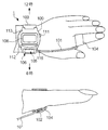
図1は、本発明の実施形態に係る腕装着型の生体活動計測装置の概観構成とともに、使用の態様を示す図である。生体活動計測装置1は、腕時計構造を有する装置本体100を備えている。装置本体100には、腕時計における12時方向から利用者(例えば患者)の腕に巻きついて6時方向で固定されるリストバンド103が設けられており、装置本体100は、リストバント103によって利用者の腕から着脱自在となっている。
【0020】
装置本体100には、液晶表示部108が設けられており、この液晶表示部108には、図2に示すように、日付、現在時刻および利用者が歩いた歩数が表示されるようになっている。装置本体100の外周部の2時方向には、ボタンスイッチ111が設けられており、詳細については後述するが、このボタンスイッチ111の押下によって液晶表示部108の表示が切り替るようになっている。ボタンスイッチ111の他にも、装置本体100の外周部の7時方向には、ボタンスイッチ112が設けられており、また、11時方向には、ボタンスイッチ113が設けられている。ボタンスイッチ112、113の各々は、利用者が各種情報を入力する際に用いられる。また、ボタンスイッチ113は、液晶表示部108が備えるEL(Electro Luminescence)バックライトを点灯させるためにも用いられる。さらに、装置本体100の表面(液晶表示部108が設けられた面)には、開始・終了ボタン116が設けられている。この開始・終了ボタン116は、利用者が運動時に当該生体活動計測装置1に対して、生体活動たる脈拍数の計測、および、体動情報たる歩数の計数の開始および終了を指示するために用いられる。
【0021】
また、図1に示すように、装置本体100の6時方向の外周部には、コネクタ部105が設けられている。このコネクタ部105には、コネクタピース106が着脱自在に取り付けられている。コネクタピース106には、ケーブル101の一端が接続されている。一方、ケーブル101の他端には、利用者の脈拍数を計測するための脈波センサユニット102が接続されている。脈波センサユニット102は、センサ用固定バンド104によって、利用者の指の根元に固定されている。この構成において、コネクタピース106がコネクタ部105と着脱自在になっているため、利用者がコネクタピース106をコネクタ部105から外すことにより、図2に示すように、本装置を腕時計としても利用できるようになっている。
【0022】
さらに、本実施形態では、コネクタ部105を保護する目的から、ケーブル101と脈波センサユニット102をコネクタ部105から外した状態では、所定のコネクタカバー(不図示)を装着するようになっている。コネクタカバーとしては、コネクタピース106と同様に構成された部品から電極部などを除いたものが用いられる。このように構成されたコネクタ構造によれば、コネクタ部105が利用者から見て手前側に配置されることになり、利用者にとって操作が簡単となる。また、コネクタ部105が装置本体100から腕時計の3時の方向に突出することのない構造となっており、利用者の手の甲がコネクタ部105に接触することがない、すなわち、利用者の手首の動きを規制することがないようになっている。
【0023】
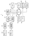
図3は、生体活動計測装置1の機能的構成を示すブロック図である。同図において、CPU130は、生体活動計測装置1の各部の動作を制御するほか、各種演算処理を実行する。ROM132は、例えばEEPROM(Electrically Erasable Programmable ROM)などの書き換え可能なものであり、CPU130によって実行される制御プログラムや各種データを記憶する。RAM134は、CPU130のワークエリアとして用いられ、CPU130による演算結果や各種データを一時的に記憶する。RAM134が記憶するデータとしては、例えば、日付や歩数の計数値、利用者の個人情報などがある。ここで、個人情報は、利用者の性別および年齢の他、身長および体重といった利用者の体格を示す情報を含むものである。計時回路136は、時刻を計時するものであり、計時結果をCPU130に出力する。入力部138は、上述したボタンスイッチ111〜113および開始・終了ボタン116に対応するものであり、利用者の各ボタン操作に応じた信号をCPU130に出力する。液晶表示部108は、上述したように各種情報を表示するものであり、CPU130の制御に従って画面表示を行う。アラーム発生部139は、CPU130からの指示に応じた音量のアラーム音を発生する。なお、アラーム発生部139は、音を発生する他にも、例えば振動モータを備え、CPU130からの指示に応じた強さの振動を発生するものであっても良い。
【0024】
脈波センサユニット102は、上述したように、利用者の生体反応たる脈波を検出し、脈波信号として脈波信号増幅回路120に出力するものである。より具体的に説明すると、図4に示すように、脈波センサユニット102は、ケース本体としてのセンサ枠1020を備えている。このセンサ枠1020の内側には、LED1022とフォトトランジスタ1024と回路基板1026が設けられている。LED1022の光放射方向には、ガラス板などから形成される透過板1028が設けられており、この透過板1028と対向するように回路基板1026が配置されている。この構成の下、LED1022から放射された光は、利用者の皮膚下の血管を介して反射され、フォトトランジスタ1024にて受光される。そして、このフォトトランジスタ1024にて光電変換された結果、脈波検出信号が得られ、回路基板1026に接続されたケーブル101を介して装置本体100に内蔵された脈波信号増幅回路120に出力される。なお、脈波センサユニット102への電力供給は、装置本体100に内蔵された電池(不図示)からケーブル101を介して行われる。
【0025】
脈波信号増幅回路120は、脈波センサユニット102からの脈波信号を増幅してA/D変換回路122に出力する。A/D変換回路122は、CPU130から制御信号が入力されている間だけ、受け取った脈波信号をアナログ/デジタル変換して、周波数分析回路124に出力する。さらに説明すると、CPU130は、A/D変換回路122を動作させる場合に、制御信号をA/D変換回路122に出力する。すなわち、CPU130がA/D変換回路122に制御信号を出力しなければ、脈波信号増幅回路120からの脈波信号は、このA/D変換回路122にて破棄されることとなる。周波数分析回路124は、デジタル信号に変換された脈波信号を一定期間取り込んで、FFT(高速フーリエ変換)処理を実行することにより脈波信号の周波数成分を算出し、脈波スペクトル信号fmgとしてCPU130に出力する。
【0026】
加速度センサユニット140は、利用者の体動たる歩行を検出するために設けられたものであり、歩行に伴う腕の振りの繰り返し運動の加速度を検出する加速度センサを備えている。加速度センサは、装置本体100に内蔵されており、利用者が歩行に伴って腕を振ったときの加速度を検出し、加速度信号として加速度信号増幅回路142に出力する。加速度信号増幅回路142は、受け取った加速度信号を増幅して、A/D変換回路122と矩形波変換回路144との各々に出力する。A/D変換回路122は、上述したように、CPU130から制御信号が入力されている間だけ、受け取った加速度信号をアナログ/デジタル変換して、周波数分析回路124に出力する。より詳細には、A/D変換回路122は、脈波信号増幅回路120からの脈波信号と加速度信号増幅回路142からの加速度信号を一定時間ごとに交互に受け取って(すなわち、時分割)周波数分析回路124に出力する。周波数分析回路124は、デジタル信号に変換された加速度信号を一定期間取り込んで、FFT処理を実行することにより加速度信号の周波数成分を算出し、加速度スペクトル信号fsgとしてCPU130に出力する。
【0027】
このように、CPU130には、周波数分析回路124から出力された脈波スペクトル信号fmgと加速度スペクトル信号fsgの各々が交互に入力されることとなる。CPU130は、受け取った脈波スペクトル信号fmgと加速度スペクトル信号fsgとから脈波を算出して、脈拍数を求めるとともに、加速度スペクトル信号fsgから歩数を求める処理を行う。なお、この処理については、後に詳述する。
【0028】
矩形波変換回路144は、加速度信号増幅回路142からの加速度信号を略矩形波に順次波形整形するものである。さらに説明すると、図5に示すように、加速度信号増幅回路142からの加速度信号1420は、利用者の歩行に伴う腕の振りの繰り返し運動に応じて略正弦波となっており、矩形波変換回路144は、加速度信号の振幅値が所定の閾値を越えた場合に、矩形パルス1422を形成する。また、矩形波変換回路144は、矩形パルス1422を形成するごとに、CPU130に歩数検出信号を出力する。CPU130は、歩数検出信号を受け取った回数を計数することで、利用者の腕の振りといった繰り返し運動の回数から歩数を計数する。ここで、矩形波変換回路144が矩形パルスを形成するときの閾値は、任意の値に設定可能である。しかしながら、上記構成にあっては、利用者が腕だけを軽く動かした場合であっても、係る動作に応じて加速度センサユニット140から加速度信号が出力されるため、閾値としては、利用者が歩行に伴って腕を動かしたときに出力される加速度信号の平均振幅値を用いることが望ましい。これにより、軽い腕の動きが排除され、より確実に利用者の歩数が検出される。
【0029】
ところで、CPU130は、利用者の歩数を求める方法として、周波数分析回路124からの加速度スペクトル信号fsgから歩数を演算する方法と、矩形波変換回路144からの歩数検出信号歩数を計数する方法との2通りの方法を用いることができるようになっている。本実施形態では、脈拍数計測が行われない場合(すなわち、運動時以外)において、利用者の1日当たりの歩数を計数すべく、矩形波変換回路144からの歩数検出信号に従って歩数の計数を行うようになっている。一方、脈拍数計測時(つまり運動時)には、周波数分析回路124からの加速度スペクトル信号fsgを基により歩数(以下、「運動時歩数」と称する)の計数を行うようになっている。運動が終了した時点で、CPU130は、運動時歩数と脈拍数計測が行われない場合(すなわち、運動時以外)の歩数とを加算する。つまり、加算された歩数は、利用者1日当りの歩数(以下、「総歩数」と称する)となる。
【0030】
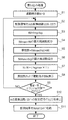
加速度スペクトル信号fsgを用いた運動時歩数の計数、および、脈波スペクトル信号fmgを用いた脈拍数計測は、利用者が開始・終了ボタン116を押下することで行われる。具体的には、CPU130が係る操作を検知すると、図6に示す割り込み処理を実行する。同図に示すように、CPU130は、運動時歩数Nを「0」に初期化する(ステップS1)。次いで、CPU130は、周波数分析回路124から信号を得るために、制御信号をA/D変換回路122に出力して、停止状態のA/D変換回路122を動作させる(ステップS2)。これにより、A/D変換回路122からデジタル信号に変換された脈波信号と加速度信号とが周波数分析回路124に出力される。周波数分析回路124は、デジタル信号に変換された脈波信号および加速度信号の各々を一定期間取り込んで、FFT処理を実行し、脈波スペクトル信号fmgと加速度スペクトル信号fsgとをCPU130に出力する。
【0031】
CPU130は、脈波スペクトル信号fmgと加速度スペクトル信号fsgとを受け取ると、脈拍数を算出すべく、脈波成分を抽出する。すなわち、CPU130は、脈波スペクトル信号fmgから加速度スペクトル信号fsgを減算して減算スペクトル信号fMを算出する(ステップS3)。ここで、脈波スペクトル信号fmgから加速度スペクトル信号fsgを減算するのは、次の理由による。すなわち、図7(a)に示すように、運動中に検出される脈波スペクトル信号fmgには、体動(すなわち、腕の動き)に応じた周波数成分である加速度スペクトル信号fsg(図7(b)参照)が含まれており、この加速度スペクトル信号fsgを除去するために、脈波スペクトル信号fmgから加速度スペクトル信号fsgを減算するのである。
【0032】
次いで、CPU130は、減算スペクトルfMに含まれる周波数成分のうち、脈波に相当する周波数として、パワーが最大である最大周波数fMmaxを求める(ステップS4)。このようにして脈波(fMmax)が求められた後、CPU130は、ステップS3にて求めた最大周波数fMmax(すなわち、脈波)を(式1)に代入して脈拍数(拍/分)を算出する(ステップS5)。
脈拍数(拍/分)=最大周波数fMmax(Hz)×60 ・・・(式1)
【0033】
次に、CPU130は、加速度スペクトル信号fsgから歩数を求めるべく、次の処理を実行する。すなわち、CPU130は、加速度スペクトル信号fsgに含まれる周波数成分のうち、1秒間当たりの歩数に相当する周波数として、パワーが最大となる最大周波数fsgmaxを求める(ステップS6)。そして、CPU130は、当該割り込み処理を1回実行する間(開始から終了までの間)に利用者が歩いた歩数を算出すべく、当該割り込み処理の実行時間に対応する時間T(sec)と最大周波数fsgmaxとを積算し、この積算結果を前回までの累積歩数である運動時歩数Nに加算する(ステップS7)。そして、CPU130は、ステップS5において算出した脈拍数と、ステップS7において算出した運動時歩数Nとを液晶表示部108に表示させる(ステップS8)。
【0034】
次に、CPU130は、利用者が脈拍数の測定を終了させるべく、開始・終了ボタン116を押下したか否かを判別する(ステップS9)。この判別結果がNOであれば、CPU130は、引き続き脈拍数の測定と歩数の計数を行うべく、処理手順をステップS2に戻す。一方、ステップS9における判別結果がYESである場合、CPU130は、A/D変換回路122への制御信号の出力を停止して(ステップS10)、A/D変換回路122の動作を停止させる。そして、CPU130は、計数した運動時歩数および脈拍数などの計測結果を日付および計測時刻等と対応付けてRAM134に記憶させ(ステップS11)、処理を終了する。また、この計測結果には、計測を開始すべく開始・終了ボタン116が押下されたときの時刻(運動開始時刻)や、割り込み処理を実行していた時間(すなわち、計測時間)なども含まれているが、これについては後述する。なお、上述した割り込み処理において、ステップS5において脈拍数を求めた後に、ステップS7において運動時歩数Nを求めたが、運動時歩数Nを求めた後に脈拍数を求めても良いことは勿論である。
【0035】
次に、生体活動計測装置1が使用されるときの具体的動作について詳述する。利用者は、生体活動計測装置1を初めて使用する場合に、先ず、日付、現在時刻および個人情報の入力、アラームの設定などを行う。具体的には、図8に示すように、日付、時刻および1日の総歩数が示されている標準画面ST1が液晶表示部108に表示されている状態において、利用者がボタンスイッチ111を所定時間(例えば3秒など)押下し続けると、CPU130が係る操作を検知して、時刻設定を行う旨を利用者に通知する時刻設定通知画面ST2を液晶表示部108に表示させる。続いて、CPU130は、時刻設定画面ST3を液晶表示部108に表示させる。ここで、時刻設定通知画面ST2にあっては、利用者が次に行うべき動作を把握しやすくするために、コントラストの強い反転表示がなされている。また、以下に説明する各通知画面にあっても、同様の理由から反転表示がなされている。
【0036】
さて、時刻設定画面ST3にあっては、設定対象となる数字が反転表示されている(図示例では、秒が設定対象)。時刻設定画面ST3が最初に表示されたときには、日付の年が最初の設定対象として反転表示されるようになっており、利用者は、日付、時刻の順で設定するようになっている。設定対象の数値変更は、利用者がボタンスイッチ112、113の各々を押下することにより行われる。具体的には、CPU130は、ボタンスイッチ112が押下されるごとに、設定対象の数値を増加させる一方、ボタンスイッチ113が押下されるごとに、設定対象の数値を減少させる。そして、利用者がボタンスイッチ111を押下すると、CPU130は、次の設定対象を反転表示させる。このようにして、利用者によって日付の年から現在時刻の秒まで順次設定される。
【0037】
そして、時刻設定画面ST3における最後の設定対象(図示例では、秒)が反転表示された状態において、利用者がボタンスイッチ111を押下すると、CPU130は、修正された日付および現在時刻をRAM134に記憶させる。次いで、CPU130は、個人情報の入力を利用者に促すべく、液晶表示部108に個人情報設定通知画面ST4を表示させた後、個人情報設定画面ST5を表示させる。
【0038】
個人情報設定画面ST5にあっては、利用者の個人情報として、性別、年齢、身長および体重が設定される。各設定対象の設定は、時刻設定画面ST3において説明した手順と同様にして行われる。そして、個人情報設定画面ST5における最後の設定対象(図示例では、体重)が反転表示された状態において、利用者がボタンスイッチ111を押下すると、CPU130は、設定された個人情報(性別、年齢、身長および体重)をRAM134に記憶させる。次いで、CPU130は、上限脈拍数とアラームの設定を利用者に促すべく、液晶表示部108に上限脈拍数・アラーム設定通知画面ST6を表示させた後、上限脈拍数・アラーム設定画面ST7を表示させる。
【0039】
この上限脈拍数・アラーム設定画面ST7にあっては、利用者に対して警告を報知すべき脈拍数の上限値と、脈拍数が上限値に達した場合に、アラーム音を鳴らすか否かの設定が行われる。脈拍数の上限値は、利用者の病状にあわせて医師が処方した処方脈拍数に応じて設定される。この処方脈拍数は、上限脈拍数と下限脈拍数とを以って示されるものであり、上限脈拍数と下限脈拍数との間に脈拍数が収まる程度の運動であれば、心臓に負担をかけすぎない適切な運動ということになる。図12は、処方脈拍数を示す図である。同図に示すように、脈拍数の上限値(以下、「上限脈拍数300a」と称する)と脈拍数の下限値(以下、「下限脈拍数300b」と称する)との拍数差は、20拍となる(以下、上限脈拍数300aと下限脈拍数300bとの間を、「許容範囲脈拍数300」と称する)。従って、この上限脈拍数・アラーム設定画面ST7において、利用者は、上限脈拍数300aを脈拍数の上限値として設定する。
【0040】
また、利用者は、上限脈拍数300aを設定するとともに、脈拍数が上限脈拍数300aを越えた旨を報知するアラーム音のオン/オフを、ボタンスイッチ112を押下することで選択する。このように、アラーム音のオン/オフが選択可能となっているので、心臓の弱い利用者(例えば、お年よりなど)がアラーム音に驚かなくて済むように、このアラーム音をオフにすることができるようになっている。
【0041】
利用者がアラーム音のオン/オフを設定した後に、ボタンスイッチ111を押下すると、CPU130は、設定された上限脈拍数300aと、アラーム音のオン/オフとをRAM134に記憶させる。また、CPU130は、設定された上限脈拍数300aから許容範囲脈拍数300の幅に相当する20拍を減算して求めた下限脈拍数300bもRAM134に記憶させる。そして、CPU130は、液晶表示部108に標準画面ST1を表示させ、これにより、各種情報の入力、設定が完了する。
【0042】
さて、利用者は、運動時の脈拍数を計測させる場合、標準画面ST1が液晶表示部108に表示されている状態において、開始・終了ボタン116を押下する。CPU130は、係る操作を検知すると、上述した割り込み処理(図6参照)を開始し、これにより脈拍数計測および運動時歩数の計数が開始される。ここで、CPU130は、周波数分析回路124から出力される脈拍数の変動幅が所定範囲内に収まるまで、図9に示すように、脈拍計測準備画面ST10を液晶表示部108に表示させるようになっている。
【0043】
そして、CPU130は、脈拍数の変動幅が所定範囲内に収まった後、利用者に対して脈拍数計測の指示を促す測定開始指示画面ST11を液晶表示部108に表示させる。利用者が脈拍数測定を開始すべく、開始・終了ボタン116を押下すると、CPU130が係る操作を検知して、測定を開始した旨を通知する測定開始通知画面ST12を液晶表示部108に表示させた後に、上述した割り込み処理を実行して測定した脈拍数および運動時歩数を示す計測画面ST13を表示させる。
【0044】
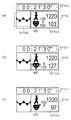
より具体的に説明すると、この計測画面ST13には、運動開始時からの経過時間を表示する経過時間表示領域ST13−1と、脈拍数と運動時歩数の測定値を表示する測定値表示領域ST13−3と、脈波波形を表示する脈波表示領域ST13−5とが含まれている。測定値表示領域ST13−3の上段側には、人が動いていることを示すマークの右横に運動時歩数が表示され、下段側には、ハートマーク400とともに脈拍数が表示される。このハートマーク400は、脈拍数に応じて異なる図像が表示されるようになっている。
【0045】
具体的には、脈拍数が許容範囲脈拍数300に収まっているときには、図10(a)に示すように、にこやかな表情をしたハートマーク400が表示される。また、利用者の脈拍数が上限脈拍数300aを越えているときには、大変そうな表情をしたハートマーク400が表示される(図10(b)参照)。さらにまた、利用者の脈拍数が下限脈拍数300bを下回っているときには、怒った表情をしたハートマーク400が表示される(図10(c)参照)。このように、利用者の脈拍数が許容範囲脈拍数300に収まっているかに応じてハートマーク400の表情が変化して表示されるので、利用者が液晶表示部108を一見すれば、心臓にかかっている負担の度合いを判断することができるようになっている。従って、利用者は、ハートマーク400が示す表情に応じて運動の激しさを調整することにより、医師に指示された適度な運動をすることができるのである。また、最近では、高強度なトレーニング(運動)の心機能の改善への有効性が示唆されている。そこで、利用者(特に心疾患患者)に対して脈拍数が下限脈拍数300bを下回っていることを示す表示を行うことにより、利用者が下限(運動)強度を意識して、適度な運動を行うことができる。
【0046】
次いで、利用者が運動を止めて測定を終了させる場合には、開始・終了ボタン116を押下する。CPU130は、係る操作を検出すると、A/D変換回路122への制御信号の出力を停止して、A/D変換回路122から周波数分析回路124への脈波信号と加速度信号の出力を停止させる。そして、CPU130は、計測結果をRAM134に記憶させる一方で、計測終了通知画面ST14を液晶表示部108に表示させた後に、標準表示画面ST15を表示させる。ここで、標準表示画面ST15に表示される総歩数には、運動前の総歩数に運動時歩数が加算された値が示されるようになっている。
【0047】
計測結果には、図13に示すように、日付と、内容とが対応付けれている。ここで内容は、計測結果が、1日における何回目の運動について記録されたものかを示すか、または、1日の各運動の合計について記録されたものであることを示す。また、計測結果には、1日分の活動情報と運動時の情報とが日付と対応付けられている。ここで、運動時の情報は、各運動ごとに計測された結果を示すものであり、時間情報と、脈拍数情報と、活動情報とを含んでいる。さらに、この時間情報は、計測開始時刻(運動開始時刻)と、計測時間(利用者が運動していた時間)とを含んでいる。また、脈拍数情報は、計測時の最高脈拍数、最低脈拍数および平均脈拍数の各々を含んでいる。さらにまた、脈拍数情報は、運動時の利用者の脈拍数が許容範囲脈拍数300に収まっていた有効累積時間と、脈拍数が上限脈拍数300aから上限脈拍数プラス10拍以内に収まっていた上限逸脱累積時間と、脈拍数が下限脈拍数300bから下限脈拍数マイナス10拍以内に収まっていた下限逸脱累積時間との各々を含んでいる。また、活動情報は、運動時の歩数と運動時の運動量とを含んでいる。この運動量の算出方法については後述する。ここで、測定結果に計測開始時刻を含めるのは、利用者が服用した薬や利用者の糖の代謝を医師などが把握できるようにするためである。また、計測結果に、有効累積時間と、上限逸脱累積時間と、下限逸脱累積時間との各々を含めるのは、利用者がどの程度の強さの運動をどの位の時間に渡って行ったかを把握できるようにするためである。
【0048】
さて、記録の内容が1日の各運動の合計である場合は、図13に示す1日分の活動情報には、1日の総歩数と、1日の基礎代謝量と、1日の運動量とが含まれている。1日の総歩数には、1日における運動回数分の運動時歩数と運動時以外歩数の合計値が記録され、また、1日の運動量には、1日における運動回数分の運動量と運動時以外の運動量の合計値が記録される。ここで、内容が1日の各運動の合計を示す場合、運動時情報と活動情報とに含まれる各項目には、次の情報が記録される。すなわち、時間情報には、1日における運動回数分の計測時間を合計した時間が記録される。また、脈拍数情報の最高脈拍数には、各運動の中で最も高い脈拍数が記録される一方、最低脈拍数には、各運動の中で最も低い脈拍数が記録される。上限逸脱累積時間、有効累積時間および下限逸脱累積時間の各々には、運動回数分の合計値が記録される。また、活動情報の運動時歩数には、運動回数分の歩数の合計値が記録され、運動時の運動量には、運動回数分の運動量の合計値が記録される。
【0049】
なお、上述したRAM134は、あらかじめ定められた日数分以上の計測結果を記憶できる容量を有することが望ましい。このあらかじめ定められた日数は、利用者(患者)が通院する日数間隔(例えば1週間など)に相当することが好ましい。このような構成とすることで、医師は、利用者(患者)が行った運動を把握できるようになる。なお、これに限らず、RAM134が数週間分の計測結果を週毎に分けて記憶する構成であっても良く、この構成により、利用者にとっては、週単位での計測結果の管理が容易となる。
【0050】
さて、上述の運動量は、次の式から求められている。
運動量(kcal)≒METS×体重(kg)×運動時間(hour)・・・(式2)
ここで、METS(Metabolic equivalents)は、運動量が安静時のエネルギー消費量の何倍に相当するかを示した指数である。METSは、米国スポーツ医学会(ACSM)によって発表されたもので、運動の強さを計る単位として一般化されている。詳細には、METSは、安静時の酸素摂取量を3.5ml/kg/minとしたときの、運動時の酸素摂取量との比を示している。なお、METSとエネルギー消費量の間には、次式の関係が成り立っている。
1METS≒1kcal/kg/hour ・・・(式3)
【0051】
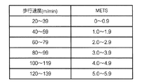
このMETSは、歩行速度から求められ、ACSMから発表されているMETSと歩行速度との対応関係を簡易に計算しやすいように換算した値が図14である。従って、運動時の歩行速度を求めることにより、運動時のMETSが特定され、そして、運動量が求められる。歩行速度は、次の式から求められる。
歩行速度=歩幅×歩数/歩行時間 ・・・(式4)
歩幅(cm)≒身長(cm)−100(cm) ・・・(式5)
(式4)の歩行速度は、単位歩行(運動)時間当たりの歩行距離であり、この歩行距離は、歩幅と歩数の乗算から算出される。なお、歩幅は歩いたときの両足のかかとからかかとまでの距離のことである。(式4)は、一般的に使用されている。また、(式5)の歩幅は、簡易的な算出方法であり、成人が通常歩行をする場合に適応される。より精度が高い運動消費量の算出を行う場合には、利用者により正確な歩幅が入力される事が好ましい。
【0052】
従って、(式5)により、利用者によって設定された身長から歩幅が求められ、さらに、この歩幅と、測定された運動時歩数と運動時間とから(式4)により、歩行速度が求められる。そして、図14に示すMETSと歩行速度との対応関係から運動時のMETSが特定され、(式2)により、運動量が求められる。CPU130は、このようにして運動量を算出して、この運動量を含む測定結果をRAM134に記憶させる。
【0053】
さて、本実施形態の生体活動計測装置1にあっては、現在時刻が「午前零時」になるごとに、1日の総歩数と、総エネルギー消費量とが算出される。より具体的に説明すると、CPU130は、現在時刻が「午前零時」になったことを検知すると、その時点までに計数した総歩数を日付と対応付けてRAM134に記憶する一方、標準画面ST1に表示すべき歩数をリセットし、歩数を0歩からカウントする。また、CPU130は、総エネルギー消費量を算出し、日付と対応付けてRAM134に記憶する。ここで、総エネルギー消費量は、次式に示すように基礎代謝量と運動量との加算により求められる。
総エネルギー消費量(kcal)=基礎代謝量+運動量 ・・・(式6)
【0054】
基礎代謝量とは、身体を維持するために生理的に必要となる最小限のエネルギー代謝量のことであり、次式によって求められる。
基礎代謝量(kcal)=基礎代謝基準値(kcal/kg/日)×体重(kg)・・・(式7)
ここで、基礎代謝基準値は、次のようにして求められる。図15は、性・年齢階層別に基礎代謝基準値を示す図であり、平成11年6月に、厚生省(現厚生労働省)によって発表された「第六次改定 日本人の栄養所要量−食事摂取基準」によるものである。この図15に従って、利用者によって設定された年齢および性別から基礎代謝基準値が特定される。そして、この基礎代謝基準値と、利用者によって設定された体重とから(式7)により基礎代謝量が求められる。CPU130は、このようにして求めた基礎代謝量と、脈拍数測定終了時に求めた運動量とから(式6)により総エネルギー消費量を求め、日付と対応付けてRAM134に記憶させる。なお、算出された1日当たりの総エネルギー消費量も、運動量と同様に、週単位でRAM134に記憶される構成が望ましい。また、体動たる歩数から総エネルギー消費量が算出される場合について例示したが、生体活動情報たる脈拍数から総エネルギー消費量が算出されるようにしても良いことは勿論である。
【0055】
利用者がRAM134に記憶された計測結果などの各種情報を液晶表示部108に表示させる場合には、標準画面ST1が表示された状態において、ボタンスイッチ112を押下する。CPU130は、係る操作を検知すると、図11に示すように、計測結果として表示すべき日付の選択を促す日付選択画面ST20を表示させる。ここで、同図において、日付選択画面ST20に示される「11月14日−1」は、11月14日の1回目の運動結果を示し、「11月14日−2」は11月14日の2回目の運動結果を示している。また、「11月14日−K」は、11月14日の1日分の運動回数分を合計した結果を表示する事を示している。
さて、利用者がボタンスイッチ112を押下して日付を選択すると、CPU130が計測結果を表示する旨を通知する結果表示通知画面ST21を液晶表示部108に表示させた後、計測開始時刻表示画面ST22を表示させる。この計測開始時刻表示画面ST22にあっては、運動開始時刻(計測開始時刻)が表示される。
【0056】
次いで、利用者がボタンスイッチ112を押下するごとに、CPU130は、運動時歩数表示画面ST23、脈拍数表示画面ST24、累積時間表示画面ST25、および総エネルギー消費量表示画面ST26を順次切り替えて液晶表示部108に表示させる。運動時歩数表示画面ST23には、計測時間(利用者が運動を行っていた時間)と、運動時歩数と、運動量(ST23の例では、213kcal)とが表示され、また、脈拍数表示画面ST24には、運動時の最高脈拍数と、最低脈拍数と、平均脈拍数とが表示される。累積時間表示画面ST25には、上限逸脱累積時間と、有効累積時間と、下限逸脱累積時間との各々が表示される。総エネルギー消費量表示画面ST26は、利用者が1日分の運動回数分を合計した結果を表示する事を日付選択画面ST20で選択した場合のみ表示されるものであり、この総エネルギー消費量表示画面ST26には、1日当たりの総歩数と、運動量と、総エネルギー消費量とが表示される。
【0057】
そして、総エネルギー消費量表示画面ST26が液晶表示部108に表示されている状態において、利用者がボタンスイッチ112を押下すると、CPU130は、結果表示終了通知画面ST27を液晶表示部108に表示させて、標準画面ST1を表示させる。
【0058】
このように、本実施形態に係る生体活動計測装置1によれば、運動中の脈拍数計測と運動時歩数の計数が行われる他、一日当たりの総歩数が計数される。さらに、運動時歩数から利用者の運動量が算出され、また、総歩数から利用者の総エネルギー消費量が算出される。これにより、利用者に対して運動中の生体活動たる脈拍数と、体動たる歩数とを示すとともに、1日当たりの総エネルギー消費量を示すことが可能となる。従って、利用者は、運動中にあっては、表示される脈拍数から、心臓にどの程度の負担がかかっているか(すなわち、運動の強度)を把握でき、さらに、総歩数や総エネルギー消費量から、一日の活動量を把握できる。
【0059】
<変形例>
上述した実施形態は、本発明の一態様を示すものであり、本発明の範囲内で任意に変更可能である。そこで以下に、各種の変形例を説明する。
【0060】
(変形例1)
上述した実施形態において、利用者の体動として歩行時の歩数が計数される構成について例示した。しかしながら、これに限らず、例えば懸垂運動や腹筋運動、縄跳び運動など利用者の動きによって回数を計数できる運動であれば、その回数を計数するようにしても良い。また、例えば、体動を検出するものとして、加速度センサユニット140を備える構成について例示したが、これに限らず、GPS(Global Positioning System)からの測位情報に従って、利用者の移動距離から歩数が算出される構成であっても良い。さらにまた、体動として歩行を検出するのではなく、例えば生体活動計測装置1が気圧センサを備え、利用者が登山した場合や、ダイビング(潜水)した場合などに生じる気圧変化から、この利用者の体動を検出するようにしても良い。
【0061】
(変形例2)
上述した実施形態において、利用者が上限脈拍数300aを設定する構成について例示したが、これに限らず、平均脈拍数の目標値(以下、「目標平均脈拍数」と称する)を設定する構成であっても良い。生体活動計測装置1は、利用者によって目標平均脈拍数が設定されると、この目標平均脈拍数から許容範囲脈拍数300や上限脈拍数300a、下限脈拍数300bなどを算出して記憶する。そして、生体活動計測装置1は、実施形態で述べたように、利用者の脈拍数の計測時にあっては、ハートマーク400の表情といった図像を変えるなどして、利用者の脈拍数がどの範囲に属しているかを表示し、また、上限逸脱累積時間や有効累積時間、下限逸脱累積時間の各々を求める。なお、生体活動計測装置1は、平均脈拍数を算出する際に、計測した脈拍数が、上限脈拍数300aを逸脱していたときの脈拍数の平均値、許容範囲脈拍数300に収まっていたときの脈拍数の平均値、および、下限脈拍数300bを下回っていたときの平均値の各々を算出しても良い。
【0062】
(変形例3)
上述した実施形態において、図12に示すように、脈拍数の範囲が3つの範囲に区分けされている場合について例示したが、これに限らず、変形例2にて説明した目標平均脈拍数を堺とした2つの範囲に区分けされても良い。また、脈拍数の範囲が3つよりも更に細かく区分けされても良い。例えば、図12において、脈拍数が上限脈拍数300a(+10拍)を越える範囲と、下限脈拍数300b(−10拍)を下回る範囲との2つの範囲を更に設けるようにしても良い。このようにすることで、利用者は、より正確に運動による心臓への負担の度合いを把握でき、運動が適正であるかを判断できる。
【0063】
(変形例4)
上述した実施形態において、利用者の脈拍数に応じた表情のハートマーク400が液晶表示部108に表示される構成について例示した。しかしながら、これに限らず、液晶表示部108がカラーで表示可能に構成され、この液晶表示部108に利用者の脈拍数に応じて異なる色のハートマーク400が表示されるようにしても良いし、また、計測された脈拍数に応じて、この脈拍数を示す数字を表示する際の態様(色、大きさなど)が変わるようにしても良い。このようにすることで、視認性が向上し、利用者が現在の脈拍数が適正かどうかを把握し易くなる。
【0064】
(変形例5)
上述した実施形態において、開始・終了ボタン116が押下された場合に、利用者の脈拍数が計測される構成について例示したが、これに限らず、CPU130が矩形波変換回路144からの歩数検出信号に従って利用者が運動を開始したかを判断し、脈拍数の計測(すなわち、図6に示す割り込み処理)を開始するようにしても良い。
【0065】
(変形例6)
上述した実施形態において、生体活動計測装置1の脈波センサユニット102が利用者の指に配置される構成について例示した。しかしながら、図16に示すように、利用者が生体活動計測装置1を装着したときに、裏蓋12に接触する部位(すなわち、手首の甲)から脈波を検出するような構成としても良い。より具体的に説明すると、図16に示すように、裏蓋12の略中央には、ガラスなどから形成された透明板1028が設けられており、その透明板1028を介して光が照射されるようにLED(不図示)が装置本体 100に内蔵される。また、フォトトランジスタ(不図示)も、透明板1028を介して受光するように、装置本体100に内蔵される。この構成によれば、利用者は、装置本体100のみを装着すれば良いこととなる。
【0066】
(変形例7)
上述した実施形態において、コネクタ部105には、ケーブル101を介して脈波センサユニット102が接続される構成について例示した。この他にも、コネクタ部105にパーソナルコンピュータなどの各種情報機器が接続されるようにしても良い。このような構成にすることで、生体活動計測装置1のRAM134に記憶された計測結果などを他の機器に記憶させることができる。また、生体活動計測装置1と医師が所有する情報機器と接続可能となれば、医師は、この情報機器にて利用者(患者)の計測結果を管理することができ、この利用者に対する適切な処方に役立てることができる。
【0067】
(変形例8)
上述した実施形態に係る生体活動計測装置1には、電池が内蔵されていた。そこで、図17に示すように、電池が消耗した場合に、利用者に対して電池交換を促す画面が液晶表示部108に表示されるように、実施形態を変形しても良い。
【0068】
(変形例9)
上述した実施形態において、脈波信号および加速度信号を周波数分析回路124にてFFT処理し、この処理によって得られた脈波スペクトル信号fmgおよび加速度スペクトル信号fsg各々の差分から脈波を算出して脈拍数を求める構成について説明した。しかしながら、これに限らず、脈波信号のみを時間周波数分析回路を用いて時間周波数分析で処理することにより脈波成分のみを取り出して脈拍数を求めるようにしても良い。時間周波数分析処理には、ウェーブレット変換処理やヴィグナービル分布が使用される。
【0069】
【発明の効果】
以上説明したように、利用者の生体活動とともに、活動量を記録することが可能な生体活動計測装置が提供される。
【図面の簡単な説明】
【図1】 本発明の実施形態に係る生体活動計測装置の概観構成とともに、使用の態様を示す図である。
【図2】 同生体活動計測装置からコネクタピースを外したときの概観構成を示す図である。
【図3】 同生体活動計測装置の機能的構成を示すブロック図である。
【図4】 同脈波センサユニットの構成を示す側断面図である。
【図5】 同矩形波変換回路の動作を説明するための図である。
【図6】 同CPUによって実行される割り込み処理の手順を示すフローチャートである。
【図7】 (a)脈波スペクトル信号を示す図である。(b)加速度スペクトル信号を示す図である。(c)脈波スペクトル信号から加速度スペクトル信号を差し引いた図である。
【図8】 同表示画面の遷移を示す図である。
【図9】 同表示画面の遷移を示す図である。
【図10】 同表示画面の遷移を示す図である。
【図11】 同表示画面の遷移を示す図である。
【図12】 同脈拍数の区分を示す図である。
【図13】 同計測結果の構成を示す図である。
【図14】 同METSと歩行速度との対応関係を示す図である。
【図15】 性・年齢階層別に基礎代謝基準値を示す図である。
【図16】 本発明の第6の変形例に係る生体活動計測装置を裏側からみた概観構成を示す図である。
【図17】 本発明の第8の変形例に係る表示画面を示す図である。
【符号の説明】
1・・・生体活動計測装置、102・・・脈波センサユニット、108・・・液晶表示部、124・・・周波数分析回路、130・・・CPU、132・・・ROM、134・・・RAM、136・・・計時回路、139・・・アラーム発生部、140・・・加速度センサユニット、144・・・矩形波変換回路、300・・・許容範囲脈拍数、300a・・・上限脈拍数、300b・・・下限脈拍数。[0001]
BACKGROUND OF THE INVENTION
The present invention relates to a life activity measuring apparatus for measuring a user's life activity.
[0002]
[Prior art]
In recent years, the number of heart disease patients is said to reach about 800,000. Cardiac disease is a condition in which coronary artery stenosis or occlusion occurs and the blood supply to the heart decreases or stops, causing cardiac dysfunction. It is broadly divided into angina. In recent years, with the advancement of medical technology, treatment within a period of about 3 hours after the onset of heart disease has been made possible by using acute reperfusion therapy or the like to suppress damage to the heart. Furthermore, when the symptom is mild, it has become possible to leave the hospital about one week after hospitalization. Thus, the survival rate of patients who have developed heart disease is high. However, heart disease is said to be closely related to so-called lifestyle-related diseases, and if lifestyle-related diseases are not improved, it is very likely that patients will recur heart disease. It is not the fundamental solution of
[0003]
Therefore, in order to improve lifestyle-related diseases, it is common for patients with heart disease to undergo rehabilitation including exercise (hereinafter referred to as “heart disease rehabilitation”) within a few months (eg, 6 months) from the onset. It has become. For example, when the symptom of heart disease is severe, the physical strength of the patient is reduced, so exercise is always taken into heart disease rehabilitation. Even if the symptoms of heart disease are mild, in order to prevent recurrence of heart disease, emphasis is placed on improving lifestyle-related diseases, and exercise is incorporated in heart disease rehabilitation. It is said that treatment of hypertension, improvement of hyperlipidemia, control of diabetes and smoking cessation are particularly effective in improving lifestyle-related diseases. For this reason, "meal", "exercise" and "drugs" It is said that it is important that each of these is prescribed in a well-balanced manner.
[0004]
By the way, since the heart disease patient has damaged the heart not a little, it is dangerous for the patient to exercise too hard so as to overload the heart. For this reason, when a patient exercises, in order to monitor the degree of burden on the heart, it is necessary to measure biological activity such as the patient's pulse rate. In recent years, in order to enable patients to exercise for heart disease rehabilitation even at home, an apparatus for measuring a pulse rate as a biological activity during exercise has been developed.
[0005]
[Problems to be solved by the invention]
However, the patient has a problem that the amount of activity in daily life cannot be grasped only by the pulse rate during exercise. Furthermore, to improve lifestyle-related diseases, it is important to exercise at the intensity prescribed by the doctor and to grasp the amount of activity in daily life. Is this intensity of exercise and activity accurately established? Is determined from the pulse rate during exercise and the amount of activity in daily life. If a user such as a patient continues to use it, it will be motivated and encouraged for exercise, and these devices will be used for health promotion.
[0006]
The present invention has been made in view of the above-described circumstances, and an object thereof is to provide a life activity measuring apparatus capable of recording an activity amount together with a user's life activity.
[0007]
[Means for Solving the Problems]
In order to achieve the above-described object, the present invention provides a body motion detection unit that detects a user's body motion, a biological reaction detection unit that detects a biological reaction of the user, and a detection result of the biological reaction detection unit. The life activity information calculation means for calculating the user's life activity information, the determination means for determining whether or not the user has started exercise, the detection result of the body movement detection means, and the determination result is affirmative There is provided a life activity measuring device comprising storage means for storing the life activity information from the time of becoming.
[0008]
According to the above-described life activity measuring device, the user's life activity information is stored in the storage means when the user is exercising, and the user's body movement is stored in the storage means when not exercising. The
[0009]
Where Life activity information calculation means May be configured to calculate the biological activity information of the user from the detection results of the body motion detection means and the biological reaction detection means. Further, the storage means may be configured to further store a detection result by the body movement detection means from when the determination result becomes affirmative. Further, the apparatus further comprises input acquisition means for acquiring an input from the user, and the determination means determines that the user has started exercising when the input acquisition means has acquired an input from the user. The determination unit may be configured to determine whether or not the user has started exercising according to the detection result of the body movement detection unit.
[0010]
Furthermore, the storage means stores the detection results per day of the body movement detection means and the life activity information for one day from when the determination result is affirmative for a predetermined number of days. A memorizing configuration is desirable. In addition, it is preferable that the storage unit further stores a detection result for one day of the body movement detection unit from when the determination result becomes affirmative. Furthermore, the storage means has a positive detection result per day from the body movement detection means, the life activity information for one day from when the determination result is positive, and the determination result is positive. It is desirable to store the detection result for one day of the body movement detection means in association with the date.
[0011]
Further, in the above-described life activity measuring device, until the determination result becomes affirmative, the detection result from the body motion detection unit is notified, while from the time when the determination result becomes affirmative, the life activity information It is desirable to have a notification means for notifying. Preferably, the notification means further notifies the detection result of the body movement detection means from when the determination result becomes affirmative after the determination result becomes affirmative. The notification means may notify the user of information by display, or may notify the information by voice.
[0012]
In the life activity measuring apparatus described above, the body motion detecting means includes an acceleration detecting means for detecting an acceleration corresponding to the body motion, and a step count calculating means for calculating the number of steps of the user according to the detected acceleration. Preferably, the biological reaction detection means detects the pulse wave of the user, and the life activity information calculation means calculates a pulse rate that is life activity information from the detected pulse wave. In addition, it is desirable that the life activity information calculating unit calculates the pulse rate from the detected pulse wave and acceleration.
[0013]
Here, the storage means stores a plurality of pulse rate ranges, and determines in which pulse rate range the pulse rate calculated by the life activity information calculation means falls within the plurality of pulse rate ranges. And a cumulative time calculating means for calculating, for each of the plurality of pulse rate ranges, a cumulative time during which the calculated pulse rate is within each of the pulse rate ranges in accordance with a determination result of the pulse rate determining means. The storage means preferably stores the calculated accumulated time for each of the plurality of pulse rate ranges.
[0014]
The storage means stores the total number of steps calculated per day by the step count calculating means and the accumulated time per day for each of the plurality of pulse rate ranges for a predetermined number of days. desirable. In addition, the structure which further memorize | stores the step count at the time of the exercise | movement for one day after the said determination result becomes affirmation may be sufficient as the said memory | storage means.
[0015]
Further, it is preferable that the apparatus further comprises display means for displaying a graphic image according to the discrimination result of the pulse rate discrimination means. In addition, it is preferable that the apparatus further includes a pulse rate range calculating unit that calculates the plurality of pulse rate ranges according to a set pulse rate that is a pulse rate set by the user. In this preferred configuration, the set pulse rate is an upper limit pulse rate in a prescription pulse rate, and the pulse rate range calculation means is configured to calculate the plurality of pulse rates from the upper limit pulse rate and the pulse rate width of the prescription pulse rate. It is preferable to calculate the range.
According to this structure, the user can grasp | ascertain the pulse rate change during exercise | movement by seeing the displayed icon, and can judge whether exercise intensity is appropriate. In addition, from each accumulated time stored in the storage unit, the user can grasp, for example, the rate at which exercise with an appropriate intensity is performed during exercise.
[0016]
Further, the storage means further stores personal information including the user's physique, and further includes an exercise amount calculation means for calculating the user's exercise amount from the detection result of the body movement detection means and the personal information. The storage means preferably stores the calculated amount of exercise per day for a predetermined number of days. In this preferred configuration, the storage means further stores personal information including the physique of the user, and the life activity information from when the determination result of the determination means becomes affirmative and the personal information It is preferable to further include an exercise amount calculating means for calculating the exercise amount of the user, and the storage means stores the calculated exercise amount per day for a predetermined number of days.
According to this configuration, the user can quantitatively grasp the amount of activity during exercise as the amount of exercise.
[0017]
Further, the storage means further stores a correspondence relationship between the basal metabolism amount and sex and age, and a basal metabolism amount specifying means for identifying the basal metabolism amount of the user from the correspondence relationship and the personal information, Total energy consumption calculating means for calculating a total energy consumption per day from the exercise quantity calculated by the exercise quantity calculating means and the basal metabolic rate specified by the basal metabolic rate specifying means; and the storage means, It is desirable to store the calculated total energy consumption for a predetermined number of days. According to this configuration, the user can know the total energy consumption amount per day in consideration of the basal metabolic rate in addition to the energy consumed by the exercise. That is, the user can grasp the amount of activity quantitatively from the total energy consumption. Note that the predetermined number of days is preferably in units of 7 days.
[0018]
DETAILED DESCRIPTION OF THE INVENTION
Hereinafter, embodiments of the present invention will be described with reference to the drawings. Below, the case where this invention is applied to the wristwatch which is an arm mounting | wearing type | mold apparatus is illustrated.
[0019]
FIG. 1 is a diagram showing an aspect of use together with an overview configuration of an arm-mounted life activity measuring apparatus according to an embodiment of the present invention. The life
[0020]
The apparatus
[0021]
Further, as shown in FIG. 1, a
[0022]
Furthermore, in this embodiment, for the purpose of protecting the
[0023]
FIG. 3 is a block diagram showing a functional configuration of the life
[0024]
As described above, the pulse
[0025]
The pulse wave
[0026]
The
[0027]
As described above, the pulse wave spectrum signal fmg and the acceleration spectrum signal fsg output from the
[0028]
The rectangular
[0029]
By the way, the
[0030]
Counting the number of steps during exercise using the acceleration spectrum signal fsg and measuring the pulse rate using the pulse wave spectrum signal fmg are performed by the user pressing the start /
[0031]
When receiving the pulse wave spectrum signal fmg and the acceleration spectrum signal fsg, the
[0032]
Next, the
Pulse rate (beats / minute) = maximum frequency fMmax (Hz) × 60 (Expression 1)
[0033]
Next, the
[0034]
Next, the
[0035]
Next, a specific operation when the life
[0036]
Now, on the time setting screen ST3, the number to be set is highlighted (in the example shown, the second is set). When the time setting screen ST3 is displayed for the first time, the year of the date is highlighted as the first setting target, and the user sets the date and time in this order. The numerical value to be set is changed when the user presses each of the button switches 112 and 113. Specifically, the
[0037]
When the user presses the
[0038]
On the personal information setting screen ST5, sex, age, height and weight are set as personal information of the user. Each setting target is set in the same manner as the procedure described in the time setting screen ST3. When the user presses the
[0039]
In the upper limit pulse rate / alarm setting screen ST7, an upper limit value of the pulse rate at which a warning is to be notified to the user, and whether or not an alarm sound is sounded when the pulse rate reaches the upper limit value. Settings are made. The upper limit value of the pulse rate is set according to the prescription pulse rate prescribed by the doctor in accordance with the medical condition of the user. This prescription pulse rate is indicated by an upper limit pulse rate and a lower limit pulse rate, and if the exercise is such that the pulse rate falls between the upper limit pulse rate and the lower limit pulse rate, the heart rate is burdened. It is an appropriate exercise that does not take too much. FIG. 12 is a diagram showing a prescription pulse rate. As shown in the figure, the pulse rate difference between the upper limit value of the pulse rate (hereinafter referred to as “upper limit pulse rate 300a”) and the lower limit value of the pulse rate (hereinafter referred to as “lower limit pulse rate 300b”) is 20 It becomes a beat (hereinafter, the range between the upper limit pulse rate 300a and the lower limit pulse rate 300b is referred to as “allowable pulse rate 300”). Therefore, on this upper limit pulse rate / alarm setting screen ST7, the user sets the upper limit pulse rate 300a as the upper limit value of the pulse rate.
[0040]
In addition, the user sets the upper limit pulse rate 300a and selects ON / OFF of the alarm sound for notifying that the pulse rate has exceeded the upper limit pulse rate 300a by pressing the
[0041]
When the user presses the
[0042]
When the user measures the pulse rate during exercise, the user presses the start /
[0043]
Then, after the fluctuation range of the pulse rate falls within a predetermined range,
[0044]
More specifically, on this measurement screen ST13, an elapsed time display area ST13-1 for displaying the elapsed time from the start of exercise, and a measured value display area ST13 for displaying measured values of the pulse rate and the number of steps during exercise. -3 and a pulse wave display area ST13-5 for displaying a pulse wave waveform. On the upper side of the measurement value display area ST13-3, the number of steps during exercise is displayed to the right of the mark indicating that a person is moving, and the
[0045]
Specifically, when the pulse rate is within the allowable range of 300, the
[0046]
Next, when the user stops the exercise and ends the measurement, the start /
[0047]
As shown in FIG. 13, the measurement result is associated with the date and the content. Here, the content indicates whether the measurement result is recorded for the number of exercises in one day, or indicates that the measurement result is recorded for the total of each exercise in one day. In addition, in the measurement result, activity information for one day and exercise information are associated with the date. Here, the information at the time of exercise | movement shows the result measured for every exercise | movement, and contains time information, pulse rate information, and activity information. Further, the time information includes a measurement start time (exercise start time) and a measurement time (time during which the user was exercising). The pulse rate information includes each of the maximum pulse rate, the minimum pulse rate, and the average pulse rate at the time of measurement. Furthermore, the pulse rate information includes the effective cumulative time that the user's pulse rate during exercise was within the allowable pulse rate 300, and the pulse rate was within the upper limit pulse rate plus 10 beats from the upper limit pulse rate 300a. Each of the upper limit deviation accumulated time and the lower limit deviation accumulated time in which the pulse rate is within the lower limit pulse rate minus 10 beats from the lower limit pulse rate 300b is included. The activity information includes the number of steps during exercise and the amount of exercise during exercise. A method for calculating this momentum will be described later. Here, the measurement start time is included in the measurement result so that a doctor or the like can grasp the medicine taken by the user and the metabolism of the user's sugar. In addition, including each of the effective accumulated time, the upper limit deviation accumulated time, and the lower limit deviation accumulated time in the measurement result indicates how much exercise the user has performed over how long. This is so that it can be grasped.
[0048]
Now, if the content of the record is the total of each exercise per day, the activity information for one day shown in FIG. 13 includes the total number of steps per day, the daily basal metabolic rate, and the daily exercise amount. And are included. The total number of steps per day for the number of exercises per day and the total number of steps other than those during the exercise are recorded in the total number of steps per day. The total value of momentum other than is recorded. Here, when the content indicates the total of each exercise for the day, the following information is recorded in each item included in the exercise information and the activity information. That is, the time information records a total time of measurement times for the number of exercises per day. The highest pulse rate in each exercise is recorded as the highest pulse rate in the pulse rate information, while the lowest pulse rate in each exercise is recorded as the lowest pulse rate. In each of the upper limit deviation accumulated time, the effective accumulation time, and the lower limit deviation accumulated time, a total value corresponding to the number of exercises is recorded. In addition, the total number of steps for the number of exercises is recorded in the number of steps in the activity information, and the total amount of exercise for the number of exercises is recorded in the amount of exercise in the exercise information.
[0049]
Note that the
[0050]
Now, the above momentum is obtained from the following equation.
Exercise amount (kcal) ≒ METS x body weight (kg) x exercise time (hour) (Equation 2)
Here, METS (Metabolic equivalents) is an index indicating how many times the amount of exercise corresponds to the energy consumption at rest. METS was published by the American Society of Sports Medicine (ACSM) and is generalized as a unit for measuring exercise intensity. Specifically, METS shows the ratio of the oxygen intake during exercise when the oxygen intake at rest is 3.5 ml / kg / min. In addition, the relationship of following Formula is formed between METS and energy consumption.
1METS ≒ 1kcal / kg / hour (Formula 3)
[0051]
This METS is obtained from the walking speed, and FIG. 14 shows a value converted so that the correspondence between the METS and the walking speed announced by ACSM can be easily calculated. Therefore, by obtaining the walking speed during exercise, the METS during exercise is specified, and the amount of exercise is obtained. The walking speed can be obtained from the following equation.
Walking speed = step length × number of steps / walking time (Formula 4)
Step length (cm) ≒ Height (cm)-100 (cm) (Formula 5)
The walking speed of (Expression 4) is a walking distance per unit walking (exercise) time, and this walking distance is calculated from multiplication of the step length and the number of steps. The stride means the distance from the heel to the heel of both feet when walking. (Formula 4) is generally used. Moreover, the stride of (Formula 5) is a simple calculation method, and is applied when an adult normally walks. When calculating the exercise consumption with higher accuracy, it is preferable that the user inputs an accurate stride.
[0052]
Therefore, the stride is obtained from the height set by the user by (Equation 5), and the walking speed is obtained from (Equation 4) from this stride, the measured number of steps during exercise, and the exercise time. Then, the METS at the time of exercise is specified from the correspondence relationship between the METS and the walking speed shown in FIG. 14, and the amount of exercise is obtained by (Equation 2). The
[0053]
Now, in the life
Total energy consumption (kcal) = basal metabolic rate + momentum (Equation 6)
[0054]
The basal metabolic rate is the minimum amount of energy metabolism that is physiologically necessary to maintain the body, and is obtained by the following equation.
Basal metabolism (kcal) = Basal metabolism reference value (kcal / kg / day) x Body weight (kg) (Equation 7)
Here, the basal metabolism reference value is obtained as follows. Fig. 15 is a diagram showing basal metabolic standard values by sex and age group. In June 1999, published by the Ministry of Health and Welfare (current Ministry of Health, Labor and Welfare) It is based on "standard". According to FIG. 15, the basal metabolism reference value is specified from the age and sex set by the user. Then, the basal metabolic rate is obtained from (Equation 7) from this basal metabolism reference value and the body weight set by the user. The
[0055]
When the user displays various information such as measurement results stored in the
When the user presses the
[0056]
Next, every time the user presses the
[0057]
When the user presses the
[0058]
As described above, according to the life
[0059]
<Modification>
The above-described embodiment shows one aspect of the present invention, and can be arbitrarily changed within the scope of the present invention. Accordingly, various modifications will be described below.
[0060]
(Modification 1)
In embodiment mentioned above, it illustrated about the structure by which the step count at the time of a walk is counted as a user's body movement. However, the present invention is not limited to this. For example, the number of times may be counted as long as the number of times can be counted by the movement of the user, such as a suspension exercise, an abdominal muscle exercise, and a jump rope exercise. In addition, for example, the configuration including the
[0061]
(Modification 2)
In the above-described embodiment, the configuration in which the user sets the upper limit pulse rate 300a is exemplified. However, the configuration is not limited to this, and a configuration in which a target value of the average pulse rate (hereinafter referred to as “target average pulse rate”) is set. There may be. When the target average pulse rate is set by the user, the life
[0062]
(Modification 3)
In the above-described embodiment, as illustrated in FIG. 12, the case where the range of the pulse rate is divided into three ranges is illustrated, but not limited to this, the target average pulse rate described in
[0063]
(Modification 4)
In the above-described embodiment, the configuration in which the
[0064]
(Modification 5)
In the above-described embodiment, the configuration in which the user's pulse rate is measured when the start /
[0065]
(Modification 6)
In embodiment mentioned above, it illustrated about the structure by which the pulse
[0066]
(Modification 7)
In the above-described embodiment, the
[0067]
(Modification 8)
The life
[0068]
(Modification 9)
In the above-described embodiment, the pulse wave signal and the acceleration signal are subjected to the FFT processing in the
[0069]
【The invention's effect】
As described above, a life activity measuring apparatus capable of recording an activity amount together with a user's life activity is provided.
[Brief description of the drawings]
FIG. 1 is a diagram showing an aspect of use together with an overview configuration of a life activity measuring apparatus according to an embodiment of the present invention.
FIG. 2 is a diagram showing a general configuration when a connector piece is removed from the biological activity measuring device.
FIG. 3 is a block diagram showing a functional configuration of the life activity measuring apparatus.
FIG. 4 is a side sectional view showing a configuration of the pulse wave sensor unit.
FIG. 5 is a diagram for explaining the operation of the rectangular wave conversion circuit;
FIG. 6 is a flowchart showing a procedure of interrupt processing executed by the CPU.
FIG. 7A is a view showing a pulse wave spectrum signal. (B) It is a figure which shows an acceleration spectrum signal. (C) It is the figure which deducted the acceleration spectrum signal from the pulse wave spectrum signal.
FIG. 8 is a diagram showing transition of the display screen.
FIG. 9 is a diagram showing transition of the display screen.
FIG. 10 is a diagram showing transition of the display screen.
FIG. 11 is a diagram showing transition of the display screen.
FIG. 12 is a diagram showing divisions of the pulse rate.
FIG. 13 is a diagram showing a configuration of the measurement result.
FIG. 14 is a diagram showing a correspondence relationship between the METS and walking speed.
FIG. 15 is a diagram showing basal metabolism reference values by sex and age group.
FIG. 16 is a diagram showing a general configuration of a life activity measuring apparatus according to a sixth modification of the present invention as seen from the back side.
FIG. 17 is a diagram showing a display screen according to an eighth modification of the present invention.
[Explanation of symbols]
DESCRIPTION OF
Claims (13)
当該検出された加速度に従って前記利用者の歩数を算出する歩数算出手段と、
前記利用者の脈波を検出する生体反応検出手段と、
当該検出された脈波から前記利用者の生体活動情報である脈拍数を算出する生体活動情報算出手段と、
前記利用者が運動を開始したか否かを判別する判別手段と、
前記生体活動情報算出手段により算出された脈拍数が、予め設定された少なくとも3つの脈拍数範囲のうち、どの脈拍数範囲に収まっているかを判別する脈拍数判別手段と、
前記脈拍数判別手段の判別結果に従って、当該算出された脈拍数が前記脈拍数範囲の各々に収まっている累積時間を前記複数の脈拍数範囲毎に算出する累積時間算出手段と、
前記判別結果が肯定になったときから、前記算出された累積時間を前記脈拍数範囲毎に記憶する記憶手段と、
前記生体活動情報算出手段により脈拍数を算出している場合に、その旨を示すハートマークを表示するとともに、当該ハートマークを、当該算出された脈拍数が収まる脈拍数範囲に対応させた表情とさせる表示手段と
を具備することを特徴とする生体活動計測装置。Body motion detection means for detecting acceleration according to the user's body motion;
Step number calculating means for calculating the number of steps of the user according to the detected acceleration;
A biological reaction detection means for detecting the pulse wave of the user;
Life activity information calculating means for calculating a pulse rate that is the user's life activity information from the detected pulse wave;
Discriminating means for discriminating whether or not the user has started exercise;
A pulse rate discriminating unit that discriminates in which pulse rate range the pulse rate calculated by the life activity information calculating unit is included in at least three preset pulse rate ranges;
In accordance with the determination result of the pulse rate determination unit, an accumulated time calculation unit that calculates the accumulated time in which the calculated pulse rate is within each of the pulse rate ranges for each of the plurality of pulse rate ranges;
Storage means for storing the calculated cumulative time for each pulse rate range since the determination result is affirmative;
When the pulse rate is calculated by the life activity information calculating means, a heart mark indicating that is displayed, and the heart mark is an expression that corresponds to a pulse rate range in which the calculated pulse rate falls A biological activity measuring device comprising: a display means for causing
ことを特徴とする請求項1に記載の生体活動計測装置。The life activity measuring device according to claim 1, wherein the life activity information calculating means calculates the life activity information of the user from detection results of the body movement detecting means and the life reaction detecting means. .
ことを特徴とする請求項2に記載の生体活動計測装置。The life activity measuring apparatus according to claim 2, wherein the storage unit further stores a detection result by the body movement detection unit from when the determination result becomes affirmative.
前記判別手段は、前記入力取得手段が前記利用者からの入力を取得した場合に、前記利用者が運動を開始したと判別する
ことを特徴とする請求項1乃至3のいずれかに記載の生体活動計測装置。It further comprises input acquisition means for acquiring input from the user,
The living body according to any one of claims 1 to 3, wherein the determination unit determines that the user has started exercise when the input acquisition unit acquires an input from the user. Activity measuring device.
ことを特徴とする請求項1乃至3のいずれかに記載の生体活動計測装置。The life activity measuring device according to any one of claims 1 to 3, wherein the determining means determines whether or not the user has started exercise according to a detection result of the body motion detecting means.
ことを特徴とする請求項1乃至3のいずれかに記載の生体活動計測装置。The storage means stores the detection result per day of the body movement detection means and the life activity information for one day from when the determination result becomes affirmative for a predetermined number of days. The life activity measuring apparatus according to any one of claims 1 to 3, wherein
ことを特徴とする請求項6に記載の生体活動計測装置。The life activity measuring apparatus according to claim 6, wherein the storage unit further stores a detection result for one day of the body movement detection unit from when the determination result becomes affirmative.
前記体動検出手段の1日あたりの検出結果と、
前記判別結果が肯定となったときからの1日分の前記生体活動情報と、
前記判別結果が肯定になったときからの、前記体動検出手段の1日分の検出結果と
を日付と対応付けて記憶する
ことを特徴とする請求項7に記載の生体活動計測装置。The storage means
A detection result per day of the body movement detection means;
The life activity information for one day from when the determination result is affirmative,
The life activity measuring apparatus according to claim 7, wherein a day-by-day detection result of the body movement detection unit from when the determination result is affirmative is stored in association with a date.
を具備することを特徴とする請求項1乃至3のいずれかに記載の生体活動計測装置。Until the determination result becomes affirmative, the detection result from the body movement detection means is notified, and when the determination result becomes affirmative, notification means for notifying the life activity information is provided. The life activity measuring device according to any one of claims 1 to 3.
ことを特徴とする請求項9に記載の生体活動計測装置。The said notification means further notifies the detection result of the said body movement detection means from when the said discrimination | determination result became affirmation from when the said discrimination | determination result became affirmation. Life activity measuring device.
前記歩数算出手段により1日あたりに算出された総歩数と、前記複数の脈拍数範囲毎の1日あたりの累積時間とを予め定められた日数分だけ記憶する
ことを特徴とする請求項1に記載の生体活動計測装置。The storage means
The total number of steps calculated per day by the step count calculating means and the accumulated time per day for each of the plurality of pulse rate ranges are stored for a predetermined number of days. The life activity measuring device described.
Priority Applications (3)
| Application Number | Priority Date | Filing Date | Title |
|---|---|---|---|
| JP2002070440A JP3852352B2 (en) | 2002-03-14 | 2002-03-14 | Life activity measurement device |
| US10/310,516 US20030176815A1 (en) | 2002-03-14 | 2002-12-05 | Physical activity measurement apparatus |
| EP03250579A EP1369082A3 (en) | 2002-03-14 | 2003-01-30 | Physical activity measurement apparatus |
Applications Claiming Priority (1)
| Application Number | Priority Date | Filing Date | Title |
|---|---|---|---|
| JP2002070440A JP3852352B2 (en) | 2002-03-14 | 2002-03-14 | Life activity measurement device |
Publications (3)
| Publication Number | Publication Date |
|---|---|
| JP2003265441A JP2003265441A (en) | 2003-09-24 |
| JP2003265441A5 JP2003265441A5 (en) | 2005-04-07 |
| JP3852352B2 true JP3852352B2 (en) | 2006-11-29 |
Family
ID=28035057
Family Applications (1)
| Application Number | Title | Priority Date | Filing Date |
|---|---|---|---|
| JP2002070440A Expired - Fee Related JP3852352B2 (en) | 2002-03-14 | 2002-03-14 | Life activity measurement device |
Country Status (3)
| Country | Link |
|---|---|
| US (1) | US20030176815A1 (en) |
| EP (1) | EP1369082A3 (en) |
| JP (1) | JP3852352B2 (en) |
Families Citing this family (81)
| Publication number | Priority date | Publication date | Assignee | Title |
|---|---|---|---|---|
| US20040264174A1 (en) * | 2003-06-30 | 2004-12-30 | Tetsushiro Tsuchiya | Light having a minus-ion generator |
| JP4758605B2 (en) * | 2003-11-20 | 2011-08-31 | 旭化成エレクトロニクス株式会社 | Step calculation device |
| US8040319B2 (en) * | 2007-04-13 | 2011-10-18 | Apple Inc. | Modifying a value based on a user's directional motions independent of cursor position |
| JP2006187469A (en) * | 2005-01-06 | 2006-07-20 | Seiko Instruments Inc | Exercise intensity evaluation apparatus |
| DE102005054152A1 (en) * | 2005-11-14 | 2007-05-16 | Viasys Healthcare Gmbh | Pulse sensor, pulse meter, oximeter, joystick and helmet |
| DE102005059435A1 (en) * | 2005-12-13 | 2007-06-14 | Robert Bosch Gmbh | Device for noninvasive blood pressure measurement |
| JP4800782B2 (en) * | 2006-02-07 | 2011-10-26 | セイコーインスツル株式会社 | Biological information measuring device |
| US20070276277A1 (en) * | 2006-05-24 | 2007-11-29 | John Booth | Device and method of manual measurement of pulse or respiratory rate |
| US8250921B2 (en) * | 2007-07-06 | 2012-08-28 | Invensense, Inc. | Integrated motion processing unit (MPU) with MEMS inertial sensing and embedded digital electronics |
| JP5338092B2 (en) * | 2008-03-07 | 2013-11-13 | セイコーエプソン株式会社 | Biological information management system |
| KR101096057B1 (en) | 2008-12-11 | 2011-12-19 | (주)마미엘 | Physical Activity Meter Using by MEMS Accelerometer |
| BRPI1016158A2 (en) * | 2009-04-26 | 2016-10-11 | Nike International Ltd | "system and method for monitoring athletic performance, and system and method for monitoring athletic performance." |
| CN102421355B (en) * | 2010-01-29 | 2014-07-16 | 北京超思电子技术股份有限公司 | Method for measuring blood oxygen of fingers and finger gripping oximeter |
| JP5432789B2 (en) * | 2010-03-25 | 2014-03-05 | シチズンホールディングス株式会社 | Athletic ability judgment device |
| JP5573282B2 (en) * | 2010-03-26 | 2014-08-20 | アイシン精機株式会社 | Biological information detection device |
| EP2437227A1 (en) * | 2010-05-26 | 2012-04-04 | Vladimir Kranz | The activation of alarm of persons in danger |
| CN108734922A (en) * | 2010-08-19 | 2018-11-02 | 斐拉迪米尔·克兰兹 | The location determination and activation of alarm of people under dangerous situation |
| US10004406B2 (en) | 2010-09-30 | 2018-06-26 | Fitbit, Inc. | Portable monitoring devices for processing applications and processing analysis of physiological conditions of a user associated with the portable monitoring device |
| US9339691B2 (en) | 2012-01-05 | 2016-05-17 | Icon Health & Fitness, Inc. | System and method for controlling an exercise device |
| US10390762B2 (en) | 2012-01-16 | 2019-08-27 | Valencell, Inc. | Physiological metric estimation rise and fall limiting |
| EP2804526A1 (en) | 2012-01-16 | 2014-11-26 | Valencell, Inc. | Reduction of physiological metric error due to inertial cadence |
| US10300334B1 (en) | 2012-02-04 | 2019-05-28 | Thomas Chu-Shan Chuang | Athletic training optimization |
| US10456077B1 (en) * | 2012-02-04 | 2019-10-29 | Thomas Chu-Shan Chuang | Athletic training optimization |
| US11103747B1 (en) | 2012-02-04 | 2021-08-31 | Thomas Chu-Shan Chuang | Athletic training optimization |
| US10499849B1 (en) * | 2012-02-04 | 2019-12-10 | Thomas Chu-Shan Chuang | Athletic training intensity |
| JP6095042B2 (en) * | 2012-07-12 | 2017-03-15 | セイコーエプソン株式会社 | Server, remote rehabilitation method, information generation method, information generation program, and remote rehabilitation system |
| EP2705789A1 (en) * | 2012-09-10 | 2014-03-12 | General Electric Company | Sensor, monitoring system and method for physiological measurement |
| USD732556S1 (en) | 2012-12-03 | 2015-06-23 | Michael Shunock | Display screen with graphical user interface |
| USD732557S1 (en) | 2012-12-03 | 2015-06-23 | Michael Shunock | Display screen with graphical user interface |
| USD743414S1 (en) * | 2012-12-03 | 2015-11-17 | Michael Shunock | Display screen with graphical user interface |
| JP6130669B2 (en) * | 2013-01-07 | 2017-05-17 | セイコーインスツル株式会社 | Biological information detection apparatus and biological information detection program |
| CN104969035B (en) | 2013-01-09 | 2019-05-10 | 瓦伦赛尔公司 | Step detection method and system based on inertia harmonic wave |
| US9728059B2 (en) | 2013-01-15 | 2017-08-08 | Fitbit, Inc. | Sedentary period detection utilizing a wearable electronic device |
| EP2969058B1 (en) | 2013-03-14 | 2020-05-13 | Icon Health & Fitness, Inc. | Strength training apparatus with flywheel and related methods |
| US20160166176A1 (en) * | 2013-07-25 | 2016-06-16 | Mayo Foundation For Medical Education And Research | Computer-based analysis of oscillatory ventilation |
| EP3974036A1 (en) | 2013-12-26 | 2022-03-30 | iFIT Inc. | Magnetic resistance mechanism in a cable machine |
| JP6281290B2 (en) * | 2014-01-15 | 2018-02-21 | Tdk株式会社 | Wristband arm movement determination device |
| WO2015131065A1 (en) | 2014-02-28 | 2015-09-03 | Valencell, Inc. | Method and apparatus for generating assessments using physical activity and biometric parameters |
| WO2015138339A1 (en) | 2014-03-10 | 2015-09-17 | Icon Health & Fitness, Inc. | Pressure sensor to quantify work |
| US9293023B2 (en) | 2014-03-18 | 2016-03-22 | Jack Ke Zhang | Techniques for emergency detection and emergency alert messaging |
| US8952818B1 (en) | 2014-03-18 | 2015-02-10 | Jack Ke Zhang | Fall detection apparatus with floor and surface elevation learning capabilites |
| EP2921105B1 (en) * | 2014-03-20 | 2018-02-28 | Physical Enterprises, Inc. (dba Mio Global) | Health risk indicator determination |
| US10117600B2 (en) * | 2014-04-15 | 2018-11-06 | Apple Inc. | Pacing activity data of a user |
| WO2015191445A1 (en) | 2014-06-09 | 2015-12-17 | Icon Health & Fitness, Inc. | Cable system incorporated into a treadmill |
| WO2015195965A1 (en) | 2014-06-20 | 2015-12-23 | Icon Health & Fitness, Inc. | Post workout massage device |
| US9852264B1 (en) * | 2014-07-21 | 2017-12-26 | Padmanabaiah Srirama | Authentic and verifiable electronic wellness record |
| JP2016047154A (en) | 2014-08-27 | 2016-04-07 | セイコーエプソン株式会社 | Biological information measurement device |
| US20160089033A1 (en) * | 2014-09-29 | 2016-03-31 | Microsoft Corporation | Determining timing and context for cardiovascular measurements |
| US9848825B2 (en) | 2014-09-29 | 2017-12-26 | Microsoft Technology Licensing, Llc | Wearable sensing band |
| US10694960B2 (en) | 2014-09-29 | 2020-06-30 | Microsoft Technology Licensing, Llc | Wearable pulse pressure wave sensing device |
| KR102315880B1 (en) * | 2014-10-22 | 2021-10-21 | 삼성전자주식회사 | Method and apparatus for managing exercise |
| US9197082B1 (en) | 2014-12-09 | 2015-11-24 | Jack Ke Zhang | Techniques for power source management using a wrist-worn device |
| US10258828B2 (en) | 2015-01-16 | 2019-04-16 | Icon Health & Fitness, Inc. | Controls for an exercise device |
| US10391361B2 (en) | 2015-02-27 | 2019-08-27 | Icon Health & Fitness, Inc. | Simulating real-world terrain on an exercise device |
| US9300925B1 (en) | 2015-05-04 | 2016-03-29 | Jack Ke Zhang | Managing multi-user access to controlled locations in a facility |
| KR20170002035A (en) * | 2015-06-29 | 2017-01-06 | 엘지전자 주식회사 | Portable device and method for evaluating physicalfitness thereof |
| US10953305B2 (en) | 2015-08-26 | 2021-03-23 | Icon Health & Fitness, Inc. | Strength exercise mechanisms |
| US10080530B2 (en) * | 2016-02-19 | 2018-09-25 | Fitbit, Inc. | Periodic inactivity alerts and achievement messages |
| US10625137B2 (en) | 2016-03-18 | 2020-04-21 | Icon Health & Fitness, Inc. | Coordinated displays in an exercise device |
| US10561894B2 (en) | 2016-03-18 | 2020-02-18 | Icon Health & Fitness, Inc. | Treadmill with removable supports |
| US10272317B2 (en) | 2016-03-18 | 2019-04-30 | Icon Health & Fitness, Inc. | Lighted pace feature in a treadmill |
| US10493349B2 (en) | 2016-03-18 | 2019-12-03 | Icon Health & Fitness, Inc. | Display on exercise device |
| US10293211B2 (en) | 2016-03-18 | 2019-05-21 | Icon Health & Fitness, Inc. | Coordinated weight selection |
| CN105911310B (en) * | 2016-04-27 | 2020-06-09 | 广州市香港科大霍英东研究院 | User motion mode detection method and device |
| US10252109B2 (en) | 2016-05-13 | 2019-04-09 | Icon Health & Fitness, Inc. | Weight platform treadmill |
| US10441844B2 (en) | 2016-07-01 | 2019-10-15 | Icon Health & Fitness, Inc. | Cooling systems and methods for exercise equipment |
| US10471299B2 (en) | 2016-07-01 | 2019-11-12 | Icon Health & Fitness, Inc. | Systems and methods for cooling internal exercise equipment components |
| WO2018023894A1 (en) * | 2016-08-01 | 2018-02-08 | 广东乐源数字技术有限公司 | Method for lighting screen of smart wristband by raising hand and smart wristband |
| CN108363475B (en) * | 2016-09-09 | 2021-04-02 | 福州扬清环保科技有限公司 | Bracelet touch reset method |
| US10671705B2 (en) | 2016-09-28 | 2020-06-02 | Icon Health & Fitness, Inc. | Customizing recipe recommendations |
| US10500473B2 (en) | 2016-10-10 | 2019-12-10 | Icon Health & Fitness, Inc. | Console positioning |
| US10376736B2 (en) | 2016-10-12 | 2019-08-13 | Icon Health & Fitness, Inc. | Cooling an exercise device during a dive motor runway condition |
| US10661114B2 (en) | 2016-11-01 | 2020-05-26 | Icon Health & Fitness, Inc. | Body weight lift mechanism on treadmill |
| TWI646997B (en) | 2016-11-01 | 2019-01-11 | 美商愛康運動與健康公司 | Distance sensor for console positioning |
| TWI680782B (en) | 2016-12-05 | 2020-01-01 | 美商愛康運動與健康公司 | Offsetting treadmill deck weight during operation |
| TWI722450B (en) | 2017-08-16 | 2021-03-21 | 美商愛康運動與健康公司 | System for opposing axial impact loading in a motor |
| US10729965B2 (en) | 2017-12-22 | 2020-08-04 | Icon Health & Fitness, Inc. | Audible belt guide in a treadmill |
| AT521597B1 (en) * | 2018-11-13 | 2020-03-15 | Smaxtec Animal Care Gmbh | Method, device and system for determining at least one state variable of the organism of a farm animal |
| US20210169355A1 (en) * | 2019-12-06 | 2021-06-10 | Savan Patel | Systems & Methods for Vascular Disease Prediction, Indication, or Diagnosis |
| CN111048211A (en) * | 2020-03-04 | 2020-04-21 | 东北师范大学 | Human motion energy consumption measuring system |
| US11426089B1 (en) * | 2020-06-25 | 2022-08-30 | Angel Medical Systems Inc. | Advanced cardiovascular monitoring system with normal, elevated, and high heartrate thresholds |
Family Cites Families (14)
| Publication number | Priority date | Publication date | Assignee | Title |
|---|---|---|---|---|
| US4367752A (en) * | 1980-04-30 | 1983-01-11 | Biotechnology, Inc. | Apparatus for testing physical condition of a subject |
| DE69215204T2 (en) * | 1992-01-29 | 1997-03-13 | Hewlett Packard Gmbh | Process and system for monitoring vital functions |
| JP3220271B2 (en) * | 1993-02-22 | 2001-10-22 | セイコーインスツルメンツ株式会社 | Pedometer with pulse meter |
| AU3070495A (en) * | 1994-07-13 | 1996-02-16 | Gw Scientific Inc. | Detection of abnormal and induction of normal heart rate variability |
| JPH08317912A (en) * | 1995-03-23 | 1996-12-03 | Seiko Instr Inc | Pulse rate meter |
| DE69632116T2 (en) * | 1995-05-12 | 2004-08-19 | Seiko Epson Corp. | DEVICE FOR DIAGNOSTICING THE STATE OF THE LIVING ORGANISM AND CONTROL UNIT |
| DE69735683T2 (en) * | 1996-03-22 | 2006-10-19 | Seiko Epson Corp. | Device for measuring the intensity of movement |
| CN1310616C (en) * | 1996-04-08 | 2007-04-18 | 精工爱普生株式会社 | Motion prescription support device |
| US6030342A (en) * | 1996-06-12 | 2000-02-29 | Seiko Epson Corporation | Device for measuring calorie expenditure and device for measuring body temperature |
| JP3523978B2 (en) * | 1997-03-18 | 2004-04-26 | セイコーエプソン株式会社 | Pulse meter |
| US5976083A (en) * | 1997-07-30 | 1999-11-02 | Living Systems, Inc. | Portable aerobic fitness monitor for walking and running |
| US6675041B2 (en) * | 1999-05-18 | 2004-01-06 | Physi-Cal Enterprises Lp | Electronic apparatus and method for monitoring net calorie intake |
| US6478736B1 (en) * | 1999-10-08 | 2002-11-12 | Healthetech, Inc. | Integrated calorie management system |
| MXPA02012643A (en) * | 2000-06-23 | 2004-09-10 | Bodymedia Inc | System for monitoring health, wellness and fitness. |
-
2002
- 2002-03-14 JP JP2002070440A patent/JP3852352B2/en not_active Expired - Fee Related
- 2002-12-05 US US10/310,516 patent/US20030176815A1/en not_active Abandoned
-
2003
- 2003-01-30 EP EP03250579A patent/EP1369082A3/en not_active Withdrawn
Also Published As
| Publication number | Publication date |
|---|---|
| JP2003265441A (en) | 2003-09-24 |
| EP1369082A2 (en) | 2003-12-10 |
| EP1369082A3 (en) | 2004-05-26 |
| US20030176815A1 (en) | 2003-09-18 |
Similar Documents
| Publication | Publication Date | Title |
|---|---|---|
| JP3852352B2 (en) | Life activity measurement device | |
| EP1338241B1 (en) | Exercise workout support device | |
| KR101000467B1 (en) | Wrist wearable type apparatus for measuring pulse and method for controlling the same | |
| EP0841034B1 (en) | Arrhythmia detector | |
| US7034694B2 (en) | Body motion detector | |
| EP0875199B1 (en) | Organism state measuring device and relaxation state indicator device | |
| JP5708341B2 (en) | Biological information processing apparatus and biological information processing method | |
| JP3301294B2 (en) | Health condition management device | |
| JPH021218A (en) | Monitor for psychotonic degree | |
| JP2003521972A (en) | Physiological monitoring device and associated calculation, display and communication device | |
| WO1997022295A1 (en) | Health care device and exercise supporting device | |
| WO2001041645A1 (en) | Calorie calculator | |
| JP3582211B2 (en) | Exercise support device | |
| JP2009240404A (en) | Physical activity level meter | |
| JP3794410B2 (en) | Health condition management device | |
| JPH09294727A (en) | Calorie consumption measuring instrument | |
| JP2004261608A (en) | Exercise aid apparatus | |
| JP3562469B2 (en) | Health condition management device | |
| JP5012866B2 (en) | Biological information processing apparatus and biological information processing method | |
| JP2004113821A (en) | Exercise formulation support system | |
| JP2004121864A (en) | Health condition managing apparatus | |
| JP5432789B2 (en) | Athletic ability judgment device | |
| JP3704829B2 (en) | Portable small electronic equipment | |
| JP3794409B2 (en) | Health condition management device | |
| JP5924426B2 (en) | Biological information processing device |
Legal Events
| Date | Code | Title | Description |
|---|---|---|---|
| A521 | Request for written amendment filed |
Free format text: JAPANESE INTERMEDIATE CODE: A523 Effective date: 20040513 |
|
| A621 | Written request for application examination |
Free format text: JAPANESE INTERMEDIATE CODE: A621 Effective date: 20040513 |
|
| A977 | Report on retrieval |
Free format text: JAPANESE INTERMEDIATE CODE: A971007 Effective date: 20050401 |
|
| A131 | Notification of reasons for refusal |
Free format text: JAPANESE INTERMEDIATE CODE: A131 Effective date: 20060516 |
|
| A521 | Request for written amendment filed |
Free format text: JAPANESE INTERMEDIATE CODE: A523 Effective date: 20060711 |
|
| TRDD | Decision of grant or rejection written | ||
| A01 | Written decision to grant a patent or to grant a registration (utility model) |
Free format text: JAPANESE INTERMEDIATE CODE: A01 Effective date: 20060815 |
|
| A61 | First payment of annual fees (during grant procedure) |
Free format text: JAPANESE INTERMEDIATE CODE: A61 Effective date: 20060828 |
|
| R150 | Certificate of patent or registration of utility model |
Free format text: JAPANESE INTERMEDIATE CODE: R150 |
|
| FPAY | Renewal fee payment (event date is renewal date of database) |
Free format text: PAYMENT UNTIL: 20090915 Year of fee payment: 3 |
|
| FPAY | Renewal fee payment (event date is renewal date of database) |
Free format text: PAYMENT UNTIL: 20100915 Year of fee payment: 4 |
|
| FPAY | Renewal fee payment (event date is renewal date of database) |
Free format text: PAYMENT UNTIL: 20100915 Year of fee payment: 4 |
|
| FPAY | Renewal fee payment (event date is renewal date of database) |
Free format text: PAYMENT UNTIL: 20110915 Year of fee payment: 5 |
|
| FPAY | Renewal fee payment (event date is renewal date of database) |
Free format text: PAYMENT UNTIL: 20120915 Year of fee payment: 6 |
|
| FPAY | Renewal fee payment (event date is renewal date of database) |
Free format text: PAYMENT UNTIL: 20130915 Year of fee payment: 7 |
|
| S531 | Written request for registration of change of domicile |
Free format text: JAPANESE INTERMEDIATE CODE: R313531 |
|
| R350 | Written notification of registration of transfer |
Free format text: JAPANESE INTERMEDIATE CODE: R350 |
|
| LAPS | Cancellation because of no payment of annual fees |