JP2016047154A - Biological information measurement device - Google Patents
Biological information measurement device Download PDFInfo
- Publication number
- JP2016047154A JP2016047154A JP2014173295A JP2014173295A JP2016047154A JP 2016047154 A JP2016047154 A JP 2016047154A JP 2014173295 A JP2014173295 A JP 2014173295A JP 2014173295 A JP2014173295 A JP 2014173295A JP 2016047154 A JP2016047154 A JP 2016047154A
- Authority
- JP
- Japan
- Prior art keywords
- heart rate
- display
- biological information
- unit
- warning
- Prior art date
- Legal status (The legal status is an assumption and is not a legal conclusion. Google has not performed a legal analysis and makes no representation as to the accuracy of the status listed.)
- Withdrawn
Links
- 238000005259 measurement Methods 0.000 title abstract description 53
- 238000000034 method Methods 0.000 description 48
- 230000008569 process Effects 0.000 description 44
- 238000001514 detection method Methods 0.000 description 29
- 238000012545 processing Methods 0.000 description 17
- 239000011521 glass Substances 0.000 description 14
- 230000006870 function Effects 0.000 description 13
- 229920005989 resin Polymers 0.000 description 13
- 239000011347 resin Substances 0.000 description 13
- 238000010586 diagram Methods 0.000 description 10
- 238000002360 preparation method Methods 0.000 description 9
- 210000000707 wrist Anatomy 0.000 description 8
- 239000000463 material Substances 0.000 description 7
- 239000011152 fibreglass Substances 0.000 description 6
- 230000004048 modification Effects 0.000 description 6
- 238000012986 modification Methods 0.000 description 6
- 239000003365 glass fiber Substances 0.000 description 5
- 239000004417 polycarbonate Substances 0.000 description 5
- 230000001133 acceleration Effects 0.000 description 4
- 210000004204 blood vessel Anatomy 0.000 description 4
- 238000004891 communication Methods 0.000 description 4
- 239000013078 crystal Substances 0.000 description 4
- 230000001186 cumulative effect Effects 0.000 description 4
- 230000000694 effects Effects 0.000 description 4
- 230000010355 oscillation Effects 0.000 description 4
- 229920000515 polycarbonate Polymers 0.000 description 4
- 230000009467 reduction Effects 0.000 description 4
- 229920000122 acrylonitrile butadiene styrene Polymers 0.000 description 3
- 239000003822 epoxy resin Substances 0.000 description 3
- 230000036541 health Effects 0.000 description 3
- 229920000647 polyepoxide Polymers 0.000 description 3
- XLYOFNOQVPJJNP-UHFFFAOYSA-N water Chemical compound O XLYOFNOQVPJJNP-UHFFFAOYSA-N 0.000 description 3
- 229920000178 Acrylic resin Polymers 0.000 description 2
- 239000004925 Acrylic resin Substances 0.000 description 2
- RYGMFSIKBFXOCR-UHFFFAOYSA-N Copper Chemical compound [Cu] RYGMFSIKBFXOCR-UHFFFAOYSA-N 0.000 description 2
- 229920002430 Fibre-reinforced plastic Polymers 0.000 description 2
- 229930182556 Polyacetal Natural products 0.000 description 2
- 239000012141 concentrate Substances 0.000 description 2
- 239000011889 copper foil Substances 0.000 description 2
- 239000011151 fibre-reinforced plastic Substances 0.000 description 2
- 238000005286 illumination Methods 0.000 description 2
- 239000007788 liquid Substances 0.000 description 2
- 229920006324 polyoxymethylene Polymers 0.000 description 2
- 229920005992 thermoplastic resin Polymers 0.000 description 2
- 230000007704 transition Effects 0.000 description 2
- WHXSMMKQMYFTQS-UHFFFAOYSA-N Lithium Chemical compound [Li] WHXSMMKQMYFTQS-UHFFFAOYSA-N 0.000 description 1
- NIXOWILDQLNWCW-UHFFFAOYSA-N acrylic acid group Chemical group C(C=C)(=O)O NIXOWILDQLNWCW-UHFFFAOYSA-N 0.000 description 1
- 230000002411 adverse Effects 0.000 description 1
- 210000003423 ankle Anatomy 0.000 description 1
- 230000005540 biological transmission Effects 0.000 description 1
- 230000004397 blinking Effects 0.000 description 1
- 230000000903 blocking effect Effects 0.000 description 1
- 230000008859 change Effects 0.000 description 1
- 238000012937 correction Methods 0.000 description 1
- 239000000835 fiber Substances 0.000 description 1
- 210000003811 finger Anatomy 0.000 description 1
- 230000005484 gravity Effects 0.000 description 1
- 238000009532 heart rate measurement Methods 0.000 description 1
- 239000004973 liquid crystal related substance Substances 0.000 description 1
- 229910052744 lithium Inorganic materials 0.000 description 1
- 230000006996 mental state Effects 0.000 description 1
- 239000000203 mixture Substances 0.000 description 1
- 238000000465 moulding Methods 0.000 description 1
- 230000002093 peripheral effect Effects 0.000 description 1
- 239000005011 phenolic resin Substances 0.000 description 1
- 229920003023 plastic Polymers 0.000 description 1
- 229920005668 polycarbonate resin Polymers 0.000 description 1
- 229920001225 polyester resin Polymers 0.000 description 1
- 239000004645 polyester resin Substances 0.000 description 1
- 238000003825 pressing Methods 0.000 description 1
- 238000010526 radical polymerization reaction Methods 0.000 description 1
- 230000002787 reinforcement Effects 0.000 description 1
- 230000004044 response Effects 0.000 description 1
- 210000004243 sweat Anatomy 0.000 description 1
- 229920001169 thermoplastic Polymers 0.000 description 1
- 229920001187 thermosetting polymer Polymers 0.000 description 1
- 239000004416 thermosoftening plastic Substances 0.000 description 1
- 210000003813 thumb Anatomy 0.000 description 1
- 238000012546 transfer Methods 0.000 description 1
- 229920001567 vinyl ester resin Polymers 0.000 description 1
Images


Classifications
-
- A—HUMAN NECESSITIES
- A61—MEDICAL OR VETERINARY SCIENCE; HYGIENE
- A61B—DIAGNOSIS; SURGERY; IDENTIFICATION
- A61B5/00—Measuring for diagnostic purposes; Identification of persons
- A61B5/02—Detecting, measuring or recording pulse, heart rate, blood pressure or blood flow; Combined pulse/heart-rate/blood pressure determination; Evaluating a cardiovascular condition not otherwise provided for, e.g. using combinations of techniques provided for in this group with electrocardiography or electroauscultation; Heart catheters for measuring blood pressure
- A61B5/024—Detecting, measuring or recording pulse rate or heart rate
- A61B5/02438—Detecting, measuring or recording pulse rate or heart rate with portable devices, e.g. worn by the patient
-
- A—HUMAN NECESSITIES
- A61—MEDICAL OR VETERINARY SCIENCE; HYGIENE
- A61B—DIAGNOSIS; SURGERY; IDENTIFICATION
- A61B5/00—Measuring for diagnostic purposes; Identification of persons
- A61B5/68—Arrangements of detecting, measuring or recording means, e.g. sensors, in relation to patient
- A61B5/6801—Arrangements of detecting, measuring or recording means, e.g. sensors, in relation to patient specially adapted to be attached to or worn on the body surface
- A61B5/6802—Sensor mounted on worn items
- A61B5/681—Wristwatch-type devices
-
- A—HUMAN NECESSITIES
- A61—MEDICAL OR VETERINARY SCIENCE; HYGIENE
- A61B—DIAGNOSIS; SURGERY; IDENTIFICATION
- A61B5/00—Measuring for diagnostic purposes; Identification of persons
- A61B5/74—Details of notification to user or communication with user or patient ; user input means
- A61B5/742—Details of notification to user or communication with user or patient ; user input means using visual displays
-
- A—HUMAN NECESSITIES
- A61—MEDICAL OR VETERINARY SCIENCE; HYGIENE
- A61B—DIAGNOSIS; SURGERY; IDENTIFICATION
- A61B5/00—Measuring for diagnostic purposes; Identification of persons
- A61B5/74—Details of notification to user or communication with user or patient ; user input means
- A61B5/746—Alarms related to a physiological condition, e.g. details of setting alarm thresholds or avoiding false alarms
-
- A—HUMAN NECESSITIES
- A61—MEDICAL OR VETERINARY SCIENCE; HYGIENE
- A61B—DIAGNOSIS; SURGERY; IDENTIFICATION
- A61B5/00—Measuring for diagnostic purposes; Identification of persons
- A61B5/02—Detecting, measuring or recording pulse, heart rate, blood pressure or blood flow; Combined pulse/heart-rate/blood pressure determination; Evaluating a cardiovascular condition not otherwise provided for, e.g. using combinations of techniques provided for in this group with electrocardiography or electroauscultation; Heart catheters for measuring blood pressure
- A61B5/024—Detecting, measuring or recording pulse rate or heart rate
- A61B5/02416—Detecting, measuring or recording pulse rate or heart rate using photoplethysmograph signals, e.g. generated by infrared radiation
- A61B5/02427—Details of sensor
Abstract
Description
本発明は、生体情報計測装置に関する。 The present invention relates to a biological information measuring device.
近年、ユーザーの心拍数を計測して表示する腕時計型の計測装置が普及している。このような計測装置は、例えば脈波センサーを備え、当該脈波センサーによってユーザーの脈波を検出する。例えば特許文献1には、ユーザーの指に固定される脈波センサーを備える計測装置が開示されている。脈波に基づいて心拍数を計測することができるので、当該計測装置を装着することで、ユーザーは心拍数の変化を確認することができる。 In recent years, wristwatch-type measuring devices that measure and display a user's heart rate have become widespread. Such a measuring device includes, for example, a pulse wave sensor, and detects the pulse wave of the user by the pulse wave sensor. For example, Patent Document 1 discloses a measuring device including a pulse wave sensor fixed to a user's finger. Since the heart rate can be measured based on the pulse wave, the user can confirm the change in the heart rate by wearing the measurement device.
心拍数を複数段階の「心拍ゾーン(以下、ゾーンという。)」に分類し、現時点の心拍数がいずれのゾーンに属しているかをユーザーに提示する計測装置が登場し始めている。このような計測装置では、各ゾーンごとに心拍数について所定の数値範囲が予め設定されている。
近年の腕時計型の計測装置の中には、各ゾーンごとに予め設定された色の光を発光することで、当該ゾーンをユーザーに提示するものがある。ゾーンをユーザーに提示する提示部は、一つの表示部(発光部)である。
ところで、ユーザーの中には、各ゾーンに対応する心拍数の数値範囲を、複数のゾーンで重複して設定することを所望する者も存在する。このように設定することで、例えばランニングの行程における特定の一区間では最も心拍数が多いゾーンを達成しつつ、他の区間では一段階低い心拍数のゾーンに係る数値範囲の上半分の心拍数は許容するといった柔軟な走行プランを実行することが容易となる。
しかしながら、上述した従来の計測装置の構成では、このようにゾーンを設定することはできず、また、提示部も互いに排他的に数値範囲が設定されたゾーンの提示のみにしか対応できない。
なお、生体情報計測装置は身体に装着して利用するものであるので、従来より小型化、薄型化、電源の長持続化が実現した使い勝手の良い構成が望まれている。具体的には、脈波センサーも外装ケース内に収納して小型化及び薄型化を実現すると共に、電源の持続時間を確保することが望まれている。
本発明は、前記の事情を鑑みて成されたものであり、携帯性(小型化・薄型化)、表示の視認性、及び電源の持続性のうちの少なくともいずれか1つを解決して使い勝手を向上させることを解決課題の一つとする。
Measuring devices that classify heart rate into a plurality of “heart rate zones (hereinafter referred to as zones)” and present to the user which zone the current heart rate belongs to have started to appear. In such a measuring apparatus, a predetermined numerical range for the heart rate is preset for each zone.
Some recent wristwatch-type measuring devices emit a light of a preset color for each zone to present the zone to the user. The presentation unit that presents the zone to the user is one display unit (light emitting unit).
By the way, some users desire to set the numerical value range of the heart rate corresponding to each zone redundantly in a plurality of zones. By setting in this way, for example, the zone with the highest heart rate is achieved in a specific section of the running process, while the heart rate in the upper half of the numerical range related to the heart rate zone that is one step lower in the other section It is easy to execute a flexible travel plan such as to allow.
However, in the configuration of the conventional measuring device described above, the zone cannot be set in this way, and the presentation unit can only deal with the presentation of the zone in which the numerical range is set exclusively.
Since the biological information measuring device is used by being worn on the body, it is desired to have a user-friendly configuration that is smaller, thinner, and lasts longer than before. Specifically, it is desired that the pulse wave sensor is also housed in the outer case to achieve a reduction in size and thickness, and to ensure the duration of the power source.
The present invention has been made in view of the above circumstances, and solves at least one of portability (downsizing / thinning), visibility of display, and sustainability of a power source, and is easy to use. It is one of the issues to be solved.
以上の課題を解決するため、本発明の一態様に係る生体情報計測装置は、生体の心拍数を示す心拍数情報を生成する心拍数情報生成部と、前記心拍数情報に基づいて、生体の心拍数が予め定められた複数の心拍範囲のうちいずれの心拍範囲に属するかを特定する特定部と、前記複数の心拍範囲の各々に対応して設けられた各表示領域と、前記特定部で特定された心拍範囲に対応する表示領域において、生体の心拍数が当該心拍範囲に属することを表示するように制御する制御部と、を備える。
この態様によれば、表示領域が複数の心拍範囲の各々に対応して二以上設けられ、各心拍領域がそれぞれ別個の表示領域で表示される。これにより、各心拍範囲に対応する心拍数の数値範囲を、複数の心拍範囲で互いに重複するように設定した場合であって、計測された心拍数が複数の心拍範囲に属する場合であっても、それぞれの心拍範囲に属することが各表示領域により適切に表示される。
In order to solve the above problems, a biological information measuring apparatus according to an aspect of the present invention includes a heart rate information generation unit that generates heart rate information indicating a heart rate of a living body, and a biological information based on the heart rate information. A specifying unit for specifying which heart rate range of a plurality of predetermined heart rate ranges, a display area provided corresponding to each of the plurality of heart rate ranges, and the specifying unit; And a control unit that controls to display that the heart rate of the living body belongs to the heart rate range in a display area corresponding to the specified heart rate range.
According to this aspect, two or more display areas are provided corresponding to each of the plurality of heartbeat ranges, and each heartbeat area is displayed in a separate display area. Thereby, even when the numerical ranges of the heart rate corresponding to each heart rate range are set so as to overlap each other in a plurality of heart rate ranges, and even when the measured heart rate belongs to a plurality of heart rate ranges, Each display area appropriately displays that it belongs to each heartbeat range.
本発明の他の態様に係る生体情報計測装置は、前記一態様に係る生体情報計測装置であって、人の入力操作に応じた操作信号を出力する操作部と、前記操作信号にもとづいて、前記複数の心拍範囲の各々について、下限の心拍数と上限の心拍数とを設定可能な設定部とを備え、前記特定部は、前記複数の心拍範囲の各々について、前記設定部によって設定された下限の心拍数及び上限の心拍数を参照して、生体の心拍数がいずれの心拍範囲に属するかを特定する。
この態様によれば、利用者が、各心拍範囲に対応する心拍数の数値範囲を、それぞれ所望の値に設定することが可能となる。
A biological information measuring device according to another aspect of the present invention is the biological information measuring device according to the one aspect, and is based on an operation unit that outputs an operation signal according to a human input operation, and the operation signal. A setting unit capable of setting a lower limit heart rate and an upper limit heart rate for each of the plurality of heart rate ranges, and the specifying unit is set by the setting unit for each of the plurality of heart rate ranges With reference to the lower limit heart rate and the upper limit heart rate, the heart rate range to which the living body belongs is specified.
According to this aspect, the user can set the heart rate numerical value ranges corresponding to the respective heart rate ranges to desired values.
本発明の他の態様に係る生体情報計測装置は、前記一態様に係る生体情報計測装置であって、前記複数の心拍範囲は、第1の心拍範囲と第2の心拍範囲とを含み、前記第1の心拍範囲に対応する表示領域が第1表示領域、前記第2の心拍範囲に対応する表示領域が第2表示領域であり、前記第1の心拍範囲の下限の心拍数を第1下限心拍数、前記第1の心拍範囲の上限の心拍数を第1上限心拍数、及び前記第2の心拍範囲の下限の心拍数を第2下限心拍数、前記第2の心拍範囲の上限の心拍数を第2上限心拍数とし、前記第2下限心拍数は、前記第1下限心拍数より大きく、且つ前記第1上限心拍数より小さいとしたとき、前記心拍数情報が示す心拍数が、前記第2下限心拍数より大きく、且つ前記第1上限心拍数より小さい場合、前記特定部は、生体の心拍数が、前記第1の心拍範囲及び前記第2の心拍範囲に属すると特定し、前記制御部は、前記第1表示部において生体の心拍数が前記第1の心拍範囲に属すること表示するように制御し、且つ前記第2表示部において生体の心拍数が前記第2の心拍範囲に属すること表示するように制御する。
この態様によれば、心拍範囲に対応する心拍数の数値範囲を、複数の心拍範囲で互いに重複するように設定することでき、例えばランニングの行程における特定の一区間では最も心拍数が多い心拍範囲を達成しつつ、他の区間では一段階低い心拍数の心拍範囲に係る数値範囲の上半分の心拍数は許容するといった柔軟な走行プランを実行することが容易となる。なお、従来の生体情報計測装置の構成では、このように心拍範囲を設定することはできない。さらに言えば、従来の生体情報計測装置の構成では、このように複数の心拍範囲を個別に表現することができないため、互いに排他的に数値範囲が設定された心拍範囲のみにしか対応できない。
The biological information measuring device according to another aspect of the present invention is the biological information measuring device according to the one aspect, wherein the plurality of heart rate ranges include a first heart rate range and a second heart rate range, The display area corresponding to the first heart rate range is the first display area, the display area corresponding to the second heart rate range is the second display area, and the lower limit heart rate of the first heart rate range is the first lower limit. The heart rate, the upper limit heart rate of the first heart rate range is the first upper limit heart rate, the lower limit heart rate of the second heart rate range is the second lower limit heart rate, and the upper limit heart rate of the second heart rate range is When the number is a second upper limit heart rate, and the second lower limit heart rate is greater than the first lower limit heart rate and less than the first upper limit heart rate, the heart rate indicated by the heart rate information is In a case where it is larger than the second lower limit heart rate and smaller than the first upper limit heart rate, the specifying unit The heart rate is specified as belonging to the first heart rate range and the second heart rate range, and the control unit displays on the first display unit that the heart rate of the living body belongs to the first heart rate range. And controlling that the second display unit displays that the heart rate of the living body belongs to the second heart rate range.
According to this aspect, the numerical value range of the heart rate corresponding to the heart rate range can be set so as to overlap each other in a plurality of heart rate ranges, for example, the heart rate range with the highest heart rate in a specific section in the running process In other sections, it is easy to execute a flexible driving plan that allows the upper half of the numerical value range related to the heart rate range of one lower heart rate in other sections. In addition, in the structure of the conventional biological information measuring device, the heart rate range cannot be set in this way. Furthermore, in the configuration of the conventional biological information measuring device, a plurality of heart rate ranges cannot be individually expressed in this way, and therefore, only a heart rate range in which a numerical range is set exclusively can be handled.
本発明の他の態様に係る生体情報計測装置は、前記一態様に係る生体情報計測装置であって、前記複数の表示領域は、画像を表示する表示部の画面に割り当てられた領域であり、当該画面のうち時計の12時方向に配置される。
この態様によれば、複数の表示領域が、当該生体情報計測装置が正置時のときの表示部の上部側に配置されるため、利用者にとって当該表示領域を視認しやすくなる。
The biological information measuring device according to another aspect of the present invention is the biological information measuring device according to the one aspect, wherein the plurality of display areas are areas assigned to a screen of a display unit that displays an image, The screen is arranged in the 12 o'clock direction of the clock.
According to this aspect, since the plurality of display areas are arranged on the upper side of the display unit when the biological information measuring device is in the normal position, the user can easily view the display areas.
本発明の他の態様に係る生体情報計測装置は、前記一態様に係る生体情報計測装置であって、利用者に警告を知らせる警告部を備え、前記設定部は、前記操作信号に基づいて、警告の対象となる一又は複数の心拍範囲である警告心拍範囲を設定可能であり、前記制御部は、前記心拍情報の示す心拍数が前記警告心拍範囲に属する場合に、警告を発するように前記警告部を制御する。
この態様によれば、利用者は警告心拍範囲を所望の数値範囲に設定することができ、利用者の心拍数が当該警告心拍範囲に属すると当該利用者に対して警告部により警告が発される。これにより、例えば利用者が自身にとって健康を害し得る危険な心拍数を警告心拍範囲として設定しておくことで、利用者自身が心拍数を常に確認せずとも、危険な心拍数に至ったときには即時そのことが利用者に警告されるため、利用者はランニングなどに集中することができる。
The biological information measuring device according to another aspect of the present invention is the biological information measuring device according to the one aspect, and includes a warning unit that notifies a user of a warning, and the setting unit is based on the operation signal, A warning heart rate range that is one or a plurality of heart rate ranges to be alerted can be set, and the control unit is configured to issue a warning when a heart rate indicated by the heart rate information belongs to the warning heart rate range. Control the warning section.
According to this aspect, the user can set the warning heart rate range to a desired numerical value range, and if the user's heart rate belongs to the warning heart rate range, the warning unit issues a warning to the user. The Thus, for example, by setting a dangerous heart rate as a warning heart rate range that can be harmful to the user's health, when the user himself reaches a dangerous heart rate without always checking the heart rate Since the user is immediately warned about this, the user can concentrate on running and the like.
本発明の他の態様に係る生体情報計測装置は、前記一態様に係る生体情報計測装置であって、利用者に警告を知らせる警告部を備え、前記設定部は、前記操作信号に基づいて、警告の対象から除外する一又は複数の心拍範囲である目標心拍範囲を設定可能であり、前記制御部は、前記心拍情報の示す心拍数が前記目標心拍範囲に属しない場合に、警告を発するように前記警告部を制御する。
この態様によれば、利用者は目標心拍範囲を所望の数値範囲に設定することができ、利用者の心拍数が当該目標心拍範囲から外れると、当該利用者に対して警告部により警告が発される。これにより、例えば利用者がランニングなどにおいて目標とする心拍数を目標心拍範囲として設定しておくことで、利用者自身が心拍数を常に確認せずとも、目標とする心拍数を外れたときには即時そのことが利用者に警告されるため、利用者はランニングなどに集中することができる。
The biological information measuring device according to another aspect of the present invention is the biological information measuring device according to the one aspect, and includes a warning unit that notifies a user of a warning, and the setting unit is based on the operation signal, A target heart rate range that is one or a plurality of heart rate ranges to be excluded from the target of warning can be set, and the control unit issues a warning when the heart rate indicated by the heart rate information does not belong to the target heart rate range. The warning unit is controlled.
According to this aspect, the user can set the target heart rate range to a desired numerical range, and if the user's heart rate is out of the target heart rate range, the warning unit issues a warning to the user. Is done. As a result, for example, by setting the target heart rate as a target heart rate range for the user in running or the like, the user does not always confirm the heart rate, but immediately when the user deviates from the target heart rate. Since this is warned to the user, the user can concentrate on running and the like.
本発明の他の態様に係る生体情報計測装置は、前記一態様に係る生体情報計測装置であって、前記複数の表示領域は、画像を表示する表示部の画面に割り当てられた領域であり、前記設定部は、前記操作信号に基づいて、警告の対象となる一又は複数の心拍範囲である警告心拍範囲を設定可能であり、前記制御部は、前記心拍情報の示す心拍数が前記警告心拍範囲に属する場合に、前記表示部に前記複数の表示領域を設定する代わりに、警告を表示する。
この態様によれば、表示部に警告を表示するときには、心拍範囲に係る表示領域を表示部に表示させない。これにより、警告を表示する面積をより大きくとることができるため、警告の効果が高められる。
The biological information measuring device according to another aspect of the present invention is the biological information measuring device according to the one aspect, wherein the plurality of display areas are areas assigned to a screen of a display unit that displays an image, The setting unit can set a warning heart rate range that is one or a plurality of heart rate ranges to be warned based on the operation signal, and the control unit can set a heart rate indicated by the heart rate information to the warning heart rate. When belonging to a range, a warning is displayed instead of setting the plurality of display areas on the display unit.
According to this aspect, when the warning is displayed on the display unit, the display area related to the heart rate range is not displayed on the display unit. Thereby, since the area which displays a warning can be taken larger, the effect of a warning is heightened.
以下、本発明の実施形態について説明する。なお、以下に説明する本実施形態は、特許請求の範囲に記載された本発明の内容を不当に限定するものではない。また本実施形態で説明される構成の全てが、本発明の必須構成要件であるとは限らない。 Hereinafter, embodiments of the present invention will be described. In addition, this embodiment demonstrated below does not unduly limit the content of this invention described in the claim. In addition, all the configurations described in the present embodiment are not necessarily essential configuration requirements of the present invention.
1.本実施形態の手法
まず本実施形態の手法について説明する。ユーザーの手首等に装着されるウェアラブル型の生体情報計測装置(いわゆるランニングウオッチ)において、光電センサーを用いて生体情報を取得する手法が知られている。光電センサーである生体センサーとしては例えば脈波センサーが考えられ、当該脈波センサーを用いることで脈拍数等の脈波信号を取得することが可能である。
1. First, the method of this embodiment will be described. 2. Description of the Related Art A technique for acquiring biological information using a photoelectric sensor in a wearable biological information measuring device (so-called running watch) worn on a user's wrist or the like is known. As a biological sensor that is a photoelectric sensor, for example, a pulse wave sensor can be considered. By using the pulse wave sensor, a pulse wave signal such as a pulse rate can be acquired.
以下では、手首に装着される腕時計型の装置を例にとって説明するが、本実施形態に係る生体情報計測装置は頸部や足首等、ユーザーの他の部位に装着されてもよい。また、本実施形態の生体センサー(光電センサー)は脈波センサーに限定されず、脈波信号以外の生体情報を取得する光電センサーが用いられてもよい。また、本実施形態の生体情報計測装置は光電センサー以外の生体センサーを含んでもよい。 In the following, a wristwatch type device attached to the wrist will be described as an example. However, the biological information measuring device according to the present embodiment may be attached to other parts of the user such as the neck and ankle. Further, the biological sensor (photoelectric sensor) of the present embodiment is not limited to the pulse wave sensor, and a photoelectric sensor that acquires biological information other than the pulse wave signal may be used. Moreover, the biological information measuring device of the present embodiment may include a biological sensor other than the photoelectric sensor.
光電センサーを含む生体情報計測装置では、必要な光を受光し、且つ不要な光を遮光する必要がある。脈波センサーの例であれば、被検体(特に計測対象の血管が含まれる部位)で反射された反射光は脈波成分を含むため受光すべきであるが、それ以外の光はノイズ成分となるため遮光すべきである。ここでの「それ以外の光」とは、発光部から射出され受光部に直接的に入射する直接光や、上記被検体以外で反射された反射光、或いは日光や照明光等の環境光が考えられる。 In a biological information measuring device including a photoelectric sensor, it is necessary to receive necessary light and shield unnecessary light. In the case of a pulse wave sensor, the reflected light reflected by the subject (particularly the site including the blood vessel to be measured) contains a pulse wave component, but should be received. Therefore, it should be shielded from light. Here, “other light” refers to direct light that is emitted from the light emitting portion and directly incident on the light receiving portion, reflected light that is reflected from other than the subject, or ambient light such as sunlight or illumination light. Conceivable.
このような透光、遮光を適切に制御するためには、生体情報計測装置は透光部と遮光部とを含んで構成されるとよい。一例としては図1等を用いて後述するように、生体情報計測装置のうち被検体側に設けられる部分(狭義にはボトムケース)における、透光部と遮光部の配置等を考慮すればよい。 In order to appropriately control such light transmission and light shielding, the biological information measuring device may include a light transmitting part and a light shielding part. As an example, as will be described later with reference to FIG. 1 and the like, the arrangement of the light transmitting portion and the light shielding portion in a portion (bottom case in a narrow sense) provided on the subject side of the biological information measuring device may be considered. .
ただし、本実施形態に係る生体情報計測装置のユースケースを想定した場合、透光部と遮光部の位置関係以外にも種々の要件を満たすことでより適切な機器を実現可能となる。 However, when a use case of the biological information measuring apparatus according to the present embodiment is assumed, a more appropriate device can be realized by satisfying various requirements in addition to the positional relationship between the light transmitting part and the light shielding part.
第1に、生体情報計測装置は高い防水性が求められる。生体情報計測装置の内部(図1の例であればトップケース21とボトムケース22の間の空間)には、回路基板40やバッテリー(二次電池128)、振動モーター(振動部129)等が含まれるため、防水性が低いとそれらの故障のおそれが生じるためである。特に腕時計型等のウェアラブル型デバイスは、運動時に装着され、運動強度等の情報提示に用いられることも考えられる。その場合、ユーザーの皮膚表面が汗でぬれることも多く、機器内部への液体、或いは水蒸気等の気体の流入の危険性を抑止しておくとよい。
First, the biological information measuring device is required to have high waterproofness. A
回路基板40には、一方の面に表示部120などの表示パネルを案内するパネル枠42が配置され、他方の面に二次電池128などを案内する回路ケース44が配置されている。
なお、回路基板40には、ガラス繊維入りのエポキシ樹脂系の基板などが用いられ、両面に銅箔などからなる配線パターンが形成されている。また、パネル枠42、回路ケース44には、ポリアセタールやポリカーボネートなどの樹脂が用いられている。
回路基板40には、光電センサーを駆動し脈拍を測定する回路、表示部120を駆動する回路、各回路を制御する回路などを構成する素子が実装されている。回路基板40は、一方の面に表示部120との接続用電極が形成され、表示部120の電極と図示しないコネクターを介して導通されている。
表示部120では、各動作モードに応じて脈拍数などの脈拍測定データや、現在時刻などの時刻情報などが表示される。各動作モードについては後述する。
On the
For the
The
The
回路ケース44には、充電可能なボタン型の二次電池128(リチウム二次電池)が格納されている。二次電池128は、両極の端子が回路基板40に接続され、電源を制御する回路へ電源を供給する。電源は、この回路で所定の電圧に変換されるなどして各回路へ供給され、光電センサーを駆動し脈拍を検出する回路、表示部120を駆動する回路、各回路を制御する回路などを動作させる。二次電池128の充電は、コイルばねなどの導通部材により回路基板40と導通された一対の充電端子を介して行われる。なお、ここでは電池として二次電池128を用いる例を説明したが、電池には、充電が不要な一次電池を用いてもよい。
The
なお、本実施形態に係る生体情報検出装置1の利用態様として、例えば運動状況の計測、及び、健康度の計測が含まれることを想定している。よって本出願人は、脈波センサー部160や、回路基板40、或いはその他部品の構成、制御手法を考慮することで長時間の連続使用が可能な生体情報検出装置1が実現する。後述する二次電池60としては、例えば150mAhのものを用いることができる。
In addition, as a utilization aspect of the biological information detection apparatus 1 which concerns on this embodiment, it is assumed that the measurement of an exercise condition and the measurement of a health degree are included, for example. Therefore, the applicant realizes the biological information detection apparatus 1 that can be used continuously for a long time by considering the configuration and control method of the pulse
第2に、ケース部(トップケース、ボトムケース)の強度が高い必要がある。上述したように、機器内部には種々の部品が配置されるが、ウェアラブル型の生体情報計測装置は、ユーザーの動きに連動して種々の力が加えられる。例えば、ユーザーがジョギング等をしていれば、腕を振ったりする動きにより、機器が押す力や、ねじる力が加えられたりする。この場合、回路基板40等の内部部品に当該力が加わってしまうと、当該部品の故障につながる。
Secondly, the case part (top case, bottom case) needs to have high strength. As described above, various components are arranged inside the device, but the wearable biological information measuring device is applied with various forces in conjunction with the movement of the user. For example, if the user is jogging or the like, a force that the device pushes or twists is applied by a movement of swinging an arm. In this case, if the force is applied to an internal component such as the
第3に、ユーザーの装着感を良好なものとする必要がある。ウェアラブル型の生体情報計測装置は、使用時にユーザーに装着される必要がある。上述したように運動時に用いるのであれば、データの取得を望む期間(例えば運動の開始時から終了時まで)、装着を継続する必要がある。或いは、ユーザーの健康度を判定する例であれば、長時間(例えば12時間、24時間、数日間と行ったスパン)、継続して生体情報の取得をする必要があり、当該期間では機器の装着を行う。そのため、生体情報計測装置の装着により、ユーザーの運動や日常生活が阻害されることは好ましくなく、良好な装着感は重要な要素となる。具体的には、生体情報計測装置は小型(薄型)であり、軽量であるとよい。つまり、生体情報計測装置は、必要な光の受光及び不要な光の遮光ができ、防水性、強度が高く、さらに小型軽量であることが望ましい。 Thirdly, it is necessary to improve the user's wearing feeling. The wearable biological information measuring device needs to be worn by the user when in use. If it is used during exercise as described above, it is necessary to continue wearing during a period when data acquisition is desired (for example, from the start to the end of exercise). Alternatively, in the example of determining the health level of a user, it is necessary to continuously acquire biometric information for a long time (for example, a span of 12 hours, 24 hours, and several days). Install. Therefore, it is not preferable that the user's exercise and daily life are hindered by wearing the biological information measuring device, and a good wearing feeling is an important factor. Specifically, the biological information measuring device is small (thin) and may be lightweight. That is, it is desirable that the biological information measuring apparatus can receive necessary light and shield unnecessary light, has high waterproofness and strength, and is small and light.
なお、図1ではケース部20はトップケース21とボトムケース22とから構成されており、ボトムケース22が透光部221及び遮光部222を有する構造としているが、これには限定されない。例えば、ケース部20を一体の部材で形成してもよいし、透明な板状部材である天板と、当該天板と組み合わされる樹脂部材とからケース部20を構成する等、種々の変形実施が可能である。以下、本明細書ではケース部20を図1の構造であるものとして説明するが、本実施形態の手法は透光部221と遮光部222を有する他の構造のケース部20を用いる場合にも適用可能である。また、図1では脈波センサー部160、検出窓2211、及び検出窓2211の周辺部分の構成を簡略化している。
このようにした場合、透光部221と遮光部222により、光電センサーで適切な光を計測に用いることが可能になる。その際、透光部221と遮光部222を一体形成しておけば、ケース部20(特にボトムケース22)の作成が容易となる。
In FIG. 1, the
In such a case, the
上記第1,第2の要求に対しては、ケース部20を変形しにくいものとすればよい。ケース部20に変形が生じやすいと、当該変形により液体や水蒸気が流入する経路が生じてしまったり、外部からの圧力が内部部品に伝わりやすくなってしまう。ここでの流入経路としては、透光部221と遮光部222の隙間が考えられる。例えば透光部221と遮光部222を共通の樹脂ベースを用いて二色成型により形成したとしても、表面が少し溶けてくっついているだけなので、水蒸気等がその間の小さな隙間に侵入する可能性がある。しかし、変形しにくいケース部20であればこれらの事態を抑止可能である。一般的に部材の厚みを増すことで変形しにくい構造とすることができるが、それでは生体情報計測装置の小型軽量化が難しく、上記第3の要求に対応できない。
In response to the first and second requests, the
その点本実施形態では、遮光部222をガラス含有樹脂材料とすることで、遮光部222を変形しにくいものとできる。そのため、遮光部222の厚みを厚くする必要がなく、防水性、強度を高くしつつ、生体情報計測装置1自体の薄型化、軽量化が可能である。つまり、遮光部222をガラス含有樹脂材料とすることで、上記の種々の課題を効率的に解決することが可能になる。
In this regard, in the present embodiment, the
さらにいえば、生体情報計測装置1を薄型にすることで、生体情報の検出精度を高くする(精度低下を抑止する)効果も期待できる。なぜなら、生体情報計測装置1に厚みがあると、長袖の服を着る時期であれば袖に触れることになり、機器自体が袖の動きに応じて揺れることになるためである。脈波センサー等の生体センサーは肌に密着させて使用したいのに、機器が揺れると浮きが生じたりするため、計測精度が低下してしまうことになる。その点、生体情報計測装置1を薄型化しておけば、袖等が接触することによる機器の浮きを抑止でき、検出精度を高くすることが可能である。 Furthermore, the effect of increasing the detection accuracy of biological information (suppressing a decrease in accuracy) can be expected by making the biological information measuring device 1 thin. This is because if the biological information measuring apparatus 1 is thick, the sleeve will be touched when it is time to wear long-sleeved clothes, and the device itself will sway according to the movement of the sleeve. Although a biological sensor such as a pulse wave sensor is desired to be used in close contact with the skin, if the device is shaken, it may be lifted, resulting in a decrease in measurement accuracy. In that respect, if the biological information measuring apparatus 1 is made thin, it is possible to suppress the floating of the device due to contact of sleeves and the like, and it is possible to increase the detection accuracy.
以下、本一実施形態に係る生体情報計測装置1の具体的な構成例について説明する。
2.生体情報計測装置の構成
図2(A)、図2(B)に本実施形態に係る生体情報計測装置1の斜視図を示す。図2(A)はトップケース21側から見た斜視図であり、図2(B)はボトムケース22側から見た斜視図である。本実施形態に係る生体情報計測装置1は、ユーザーの所与の部位(例えば手首)に装着され、脈波信号等の生体情報を検出する。生体情報計測装置1は、ユーザーに密着されて生体情報を検出する機器本体10と、機器本体10に取り付けられ機器本体10をユーザーに装着するためのバンド部15と、を有する。
Hereinafter, a specific configuration example of the biological information measuring apparatus 1 according to the present embodiment will be described.
2. Configuration of Biological Information Measuring Device FIGS. 2A and 2B are perspective views of the biological information measuring device 1 according to this embodiment. 2A is a perspective view seen from the
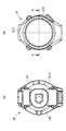
機器本体10は、トップケース21と、ボトムケース22とを有する。図3(A)、図3(B)は生体情報計測装置1のうちの機器本体10部分を表す図である。図3(A)はボトムケース22からトップケース21へ向かう方向、すなわち生体情報計測装置1がユーザーに装着されて使用される状況における、被検体(ユーザー手首)側から観察した方向での平面図である。また、図3(B)は図3(A)とは反対側、すなわちトップケース21からボトムケース22へ向かう方向での平面図である。つまり、図3(A)は主としてボトムケース22の構造を表す平面図であり、図3(B)は主としてトップケース21の構造を表す平面図である。
The device
図3(A)に示したように、ボトムケース22には検出窓2211が設けられ、検出窓2211に対応する位置に脈波センサー部160が設けられる。検出窓2211においては光が透過する構成となっており、脈波センサー部160に設けられる光電センサー(脈波を検出するセンサー)のうちの発光部から発光される光は、検出窓2211を透過して被検体に対して照射される。また、被検体での反射光も検出窓2211を透過し、脈波センサーのうちの受光部において受光される。つまり、検出窓2211を設けることで、光電センサーを用いた生体情報の検出が可能になる。具体的には、検出窓2211は透光部221(図1参照)により実現される(透光部221が検出窓2211を含む)ものとすればよい。透光部221の具体的な構造については後述する。
As shown in FIG. 3A, the
図3(B)に示したように、トップケース21は、胴部211とガラス板212を備えてもよい。この場合、胴部211及びガラス板212は、内部構造を保護する外壁として用いられるとともに、ガラス板212を介して、ガラス板212の直下に設けられる液晶ディスプレイ(図1に示す表示部120)等の表示をユーザーが閲覧可能な構成としてもよい。つまり本実施形態の生体情報計測装置1では、検出した生体情報や運動状態を表す情報、或いは時刻情報等の種々の情報を表示部120を用いて表示し、当該表示をトップケース21側からユーザーに提示するものであってもよい。なお、ここでは生体情報計測装置1の天板部分をガラス板212により実現する例を示したが、表示部120を閲覧可能な透明部材であり、表示部120等のケース部20の内部に含まれる構成を保護可能な程度の強度を有する部材であれば、透明のプラスチック等、ガラス以外の材料により天板部分を構成することが可能である。
As shown in FIG. 3B, the
次に、生体情報計測装置1のうちの機器本体10(図2参照)の詳細な断面構造の例を図1を用いて説明する。図1は図3(B)におけるA−A’での断面図であり、図1の紙面上方がトップケース21側であり、紙面下方がボトムケース22側である。
Next, an example of a detailed cross-sectional structure of the device main body 10 (see FIG. 2) in the biological information measuring apparatus 1 will be described with reference to FIG. FIG. 1 is a cross-sectional view taken along line A-A ′ in FIG. 3B, and the upper side of the drawing in FIG. 1 is the
図1に示したように、機器本体10は、トップケース21とボトムケース22の他に、脈波センサー部160と、回路基板40と、パネル枠42と、回路ケース44と、二次電池128と、表示部120と、振動部129と、アンテナ130と、を含む。ただし、生体情報計測装置1の構成は図1に限定されず、他の構成を追加したり、一部の構成を省略することが可能である。
As shown in FIG. 1, in addition to the
脈波センサー部160は、上述したように光電センサーを備えている。これによれば、生体情報計測装置1は、脈波センサー部160が光電センサーを備えてなることから、その特性により、生体情報として例えば脈波を計測し、これに基づいて脈拍数や血管の固さ、運動に関する状態や精神的な状態などを導出することができる。
The pulse
光電センサーは、LED(Light Emitting Diode)などの発光部からユーザーの手首に向けて照射され手首の血管で反射された光を、集光ミラーで集光し、フォトダイオードなどの受光部で受光する。この際、光電センサーは、血管の拡張時と収縮時とで光の反射率が異なる現象を利用してユーザーの脈拍を計測する。このことから、脈波センサー部160は、計測ノイズとなる光が光電センサーの受光素子で受光されないように、手首に押圧されていることが好ましく、手首に密着していることがより好ましい。
The photoelectric sensor collects light reflected from the blood vessel of the wrist irradiated from the light-emitting unit such as an LED (Light Emitting Diode) by a condenser mirror and received by a light-receiving unit such as a photodiode. . At this time, the photoelectric sensor measures a user's pulse by using a phenomenon in which the reflectance of light is different between when the blood vessel is dilated and when it is contracted. Therefore, it is preferable that the pulse
回路基板40には、一方の面に表示部120等の表示パネルを案内するパネル枠42が配置され、他方の面に二次電池128などを案内する回路ケース44が配置されている。
On the
なお、回路基板40には、ガラス繊維入りのエポキシ樹脂系の基板などが用いられ、両面に銅箔などからなる配線パターンが形成されている。また、パネル枠42、回路ケース44には、ポリアセタールやポリカーボネートなどの樹脂が用いられている。
For the
回路基板40は、表示部120の表示を制御したり、アンテナ30で受信した衛星信号を処理したりする各種IC等で構成されるMCU(メモリーコントロールユニット)136が実装されている。このMCU136に実装されたメインコントロールの制御により、表示部120上には、走行速度、走行距離、走行時間、走行ペース(例えば、1km当たりの所要時間(分))、ピッチ(1分当たりの歩数)、歩数などの走行情報を表示するようになっている。回路基板40は、一方の面に表示部120との接続用電極が形成され、表示部120の電極と図示しないコネクターを介して導通されている。
The
以上に示したように、本実施形態に係る生体情報計測装置1は、ケース部20に設けられる二次電池128と、ケース部20のうち、二次電池128に対して被検体との接触面側とは反対側に設けられ、生体情報計測装置1の処理装置が実装される回路基板40を含む。生体情報計測装置1が図1の構成であれば、生体情報計測装置1は、トップケース21とボトムケース22の間に設けられる二次電池128と、二次電池128とトップケース21との間に設けられ、生体情報計測装置1の処理装置が実装される回路基板40を含む、と言い換えることも可能である。ここで、二次電池128と回路基板40は、被検体との接触面側から見た平面視(図3(A)に対応)において、生体情報計測装置1の中央部に設けられるものであってもよい。
As described above, the biological information measuring apparatus 1 according to the present embodiment includes the
また、生体情報計測装置1は、ケース部20(狭義にはボトムケース22)を被検体との接触面側から見た平面視において、二次電池128に比べて生体情報計測装置1の端部側に設けられる振動部129(振動モーター)を含んでもよい。振動部129は例えば何らかの通知をユーザーに行うものであってもよく、表示部120とは異なるユーザーインターフェースとして利用可能である。図1の例であれば、振動部129は二次電池128よりも右端側に設けられている。
In addition, the biological information measuring apparatus 1 has an end portion of the biological information measuring apparatus 1 as compared with the
次に、透光部221と遮光部222の断面構造の詳細について説明する。図1からわかるように、遮光部222は、検出窓2211以外の部分において、被検体側から透光部221を覆うように設けられる。
検出窓2211では透光部221は遮光部222に覆われることはない、言い換えれば検出窓2211は透光部221により実現される。このため、上述したように脈波センサー部160に設けられる光電センサーでは、発光部311から被検体に対して光を照射することや、受光部において被検体での反射光を受光することができ、脈波信号等の生体情報を検出することが可能になる。
Next, details of the cross-sectional structures of the
In the
一方、検出窓2211以外の部分では、透光部221は、被検体側(図1の紙面下方側)から遮光部222により覆われる。このようにすれば、脈波センサー部160に入射する光を制限することが可能になる。そのため、受光したい光、すなわち発光部から照射され被検体により反射された反射光を受光可能としつつ、ノイズ源となる光、例えば太陽光や照明光等の環境光の受光を抑止することができ、生体情報の検出精度を向上させることが可能である。
On the other hand, in a portion other than the
また、遮光部222が透光部221を覆うという構造は他の観点から捉えることも可能である。具体的には、本実施形態の生体情報計測装置1では、生体情報計測装置1がユーザー(被検体)に装着された状態において、被検体からケース部20へと向かう方向(狭義にはボトムケース22からトップケース21へと向かう方向)を第1の方向DR1とした場合に、検出窓2211以外の部分において、遮光部222の第1の方向DR1側に、透光部221が設けられている。
Further, the structure in which the
透光部221は光を透過する以上、透光部221が設けられる部分は、当該部分を介して光の流入の可能性を考慮しなくてはいけない。ここで、透光部221はボトムケース22に設けられるのであるから、考慮すべき光の入射方向とは、被検体からボトムケース22へ向かう方向、すなわち第1の方向DR1である。この際、遮光部222のDR1側に透光部221が設けられるものとすれば、検出窓2211以外での透光部221への光は、遮光部222による遮光の影響を受けると考えられるため、脈波センサー部160へのノイズ源となる光の入射を抑止できる。
Since the
なお、図1の例からもわかるように、遮光部222のDR1側に透光部221が設けられるとは、遮光部222の全ての領域に関して、それよりもDR1側に透光部221が設けられることを表すものではない。例えば図1のRBに示した領域のように、遮光部222のDR1側に透光部221が配置されない領域があってもよい。つまり、遮光部222のDR1側に透光部221が設けられるとは、透光部221が設けられる場合には、検出窓2211の部分を除いて、それよりもDR1とは反対方向側に遮光部222が設けられるということであってもよい。具体的には図1のRAに示した領域、すなわち検出窓2211以外の透光部221が設けられる領域では、透光部221は遮光部222よりもDR1側となっている。
As can be seen from the example of FIG. 1, the provision of the
ここで、透光部221は樹脂材料で形成され、遮光部222はガラス(狭義にはガラス繊維)を含有させたガラス含有樹脂材料で形成される。具体的には、透光部221は、ポリカーボネート又はABS樹脂又はアクリル樹脂により形成され、遮光部222は、ガラスが含有されたポリカーボネート、又はガラスが含有されたABS樹脂、又はガラスが含有されたアクリル樹脂により形成されてもよい。
Here, the
つまり本実施形態に係る遮光部222は、FRP(Fiber Reinforced Plastics、繊維強化樹脂)であってもよく、特にそのうちの、強化に用いる繊維としてガラス繊維を用いたGFRP(Glass Fiber Reinforced Plastics)であってもよい。GFRPでは、ガラス繊維とともに用いる樹脂として、熱可塑性樹脂を用いてもよく、本実施形態では熱可塑性樹脂としてポリカーボネートやABS樹脂を用いることが可能である。また、アクリル樹脂は熱可塑性のものと熱硬化性のものが知られているが、本実施形態ではそのどちらを用いることも可能である。GFRPはFRPの中でも安価であり、一般的なものであるため、GFRPを採用することで本実施形態に係る遮光部222を容易に実現することが可能である。なお、GFRPにおける樹脂材料としてはポリエステル樹脂、ビニルエステル樹脂、エポキシ樹脂、フェノール樹脂等、種々の樹脂材料が利用可能であり、本実施形態に係る遮光部222はそれらを広く用いることが可能である。
That is, the light-shielding
以上説明した構造を採用することで、小型(薄型)化及び軽量化が実現し、具体的には本実施形態に係る生体情報検出装置1は、重量を60gに抑えることが可能になり、外装ケース(ケース部20)の平面サイズを6cm以下、ケース厚みを15mm以下で構成することが可能になった。ここでケース部20の平面サイズとは、後述する図3(A)のように、生体情報検出装置1がユーザーに装着されて使用される状況における、被検体(ユーザー手首)側から観察した方向での平面図でのサイズを表し、ケース厚みとはそれに直交する方向(例えば図1におけるDR1方向)でのサイズを表す。具体的には、平面図でのケース部20の長さのうちの最大値が6cm以下とし、DR1方向での厚みのうちの最大値が15mm以下とすることが可能である。
By adopting the structure described above, a reduction in size (thinness) and a reduction in weight can be realized. Specifically, the biological information detection apparatus 1 according to the present embodiment can suppress the weight to 60 g, and the exterior The case (case part 20) can be configured to have a planar size of 6 cm or less and a case thickness of 15 mm or less. Here, the planar size of the
図4は、生体情報計測装置1のシステム構成の一例を示すブロック図である。同図に示すように、生体情報計測装置1には、電源回路124、表示部120、フラッシュROM134、アンテナ130、無線通信部135、振動部129、ライト137、加速度センサー138、水晶発振回路139、リセット回路141、記憶部159、脈波センサー部160、及び操作ボタン151〜154が、MCU136に接続されて設けられている。
FIG. 4 is a block diagram illustrating an example of a system configuration of the biological information measuring apparatus 1. As shown in the figure, the biological information measuring apparatus 1 includes a
MCU136は、内部にプログラムを記憶するメモリーを備えており、生体情報計測装置1の各部の制御を行う他、時刻情報の生成処理、後述するようなタップ検出処理、使用者の走行状態の記憶処理、及び、速度算出処理などを行うようになっている。電源回路124は、接続端子(不図示)を介してACアダプタ142と接続された場合、二次電池128を充電する。二次電池128は、表示部120やアンテナ130などに駆動電力を供給する。
The
フラッシュROM134には、例えば時差情報が記憶されている。時差情報は、時差データ(座標値(例えば、緯度及び経度)に関連付けられたUTCに対する補正量等)が定義された情報である。また、後述するように、体振動周波数と、速度との相関関係もこのフラッシュROM134に記録される。
アンテナ130は、例えば1.5GHz帯の衛星信号から航法メッセージに含まれる衛星軌道情報、GPS時刻情報、あるいは位置情報等の衛星情報を取得する処理を行う。
る。
The
The
The
無線通信部135は、生体情報計測装置1とパーソナルコンピュータ等との無線通信を行い、生体情報計測装置1に記憶したログデータ等をパーソナルコンピュータ等に送信できるようになっている。ライト137は、使用者による操作ボタンの操作により、表示部120に光を照射して、夜間などに使用者による視認を容易にするために用いられる。なお、図示していないが、使用者の設定処理の完了を知らせるため等に用いられるブザーも設けられている。
The
水晶発振回路139は、温度補償回路付きの水晶発振回路であり、温度に関係なくほぼ一定の周波数の基準クロック信号を生成する。リセット回路141は、ユーザーによる所定の操作に応じて、生体情報計測装置1の計測状態をリセットさせるために用いられる。
The
ここで、本一実施形態に係る生体情報計測装置1が有する動作モードと、動作モードの切り替えに関して操作ボタン151〜154が担う主要な機能について詳細に説明する。
本実施形態に係る生体情報計測装置1は、少なくとも、第1のモードである「時刻表示モード」と、第2のモードである「計測モード」と、第3のモードである「心拍表示モード」との三つの動作モードを有する。
Here, an operation mode of the biological information measuring apparatus 1 according to the present embodiment and main functions of the
The biological information measuring apparatus 1 according to this embodiment includes at least a “time display mode” that is a first mode, a “measurement mode” that is a second mode, and a “heart rate display mode” that is a third mode. And has three operation modes.
図5は、生体情報計測装置1が「時刻表示モード」であるときの表示部120の表示例を示す図である。時刻表示モードは、当該生体情報計測装置1を主に時刻表示のために(腕時計として)利用する際に設定する動作モードである。
時刻表示モードでは、脈波センサー部160(光電センサー)及びアンテナ130は、MCU136によって停止状態に設定され、脈波信号の取得及び衛星情報の取得に係る処理は実行されない。そして、主要な表示として図5に示すように時刻情報505が表示部120に表示される。なお、図5に示す例では、日付情報504も表示部120に表示されている。
図5に示す電池表示451は、二次電池128の残量を示す表示であり、矩形形状のマーク451sの表示個数が少ないほど二次電池128の残量が少ないことを示す。
FIG. 5 is a diagram illustrating a display example of the
In the time display mode, the pulse wave sensor unit 160 (photoelectric sensor) and the
A
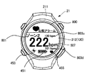
図6は、生体情報計測装置1が「計測モード」であるときの表示部120の表示例を示す図である。計測モードは、当該生体情報計測装置1をいわゆるランニングウォッチとして利用する際に設定する動作モードである。
計測モードでは、MCU136によって、脈波センサー部160及びアンテナ130が動作状態に設定され、脈波信号の取得と衛星情報の取得に係る処理が実行される。同図に示す衛星表示453は、アンテナ130が動作状態であることを示す表示である。同図に示すハート表示455は脈波センサー部160が動作状態であることを示す表示である。
FIG. 6 is a diagram illustrating a display example of the
In the measurement mode, the pulse
また、ゾーン表示506は、現在のユーザーの心拍数が、予め設定された複数(本例では五つ)の心拍ゾーン(上限値と下限値とで規定された心拍数の数値範囲;心拍範囲)のいずれに属するかを示す表示である。
ここでは、ゾーン表示506を構成する五つの円形表示は、左から順に「心拍ゾーン1」、「心拍ゾーン2」、「心拍ゾーン3」、「心拍ゾーン4」、「心拍ゾーン5」に対応しており、点灯(同図において黒色表示)されている円形表示がユーザーの現在の心拍数が属する心拍ゾーンである。図6に示す例では、ユーザーの心拍数は、心拍ゾーン4に属する。以下、心拍ゾーンを単に「ゾーン」という。
In addition, the
Here, the five circular displays constituting the
計測モードにおいて、MCU136は、脈波センサー部160によって取得された脈波信号に基づいて、一定の時間(本例では1分間)に心臓が拍動する回数(以下、「心拍数」という。)を算出し、該心拍数を示す心拍数情報を生成して記憶部159に記憶させると共に、図6に示すように心拍数情報507を表示部120に表示させる。
なお、心拍数は実測値であってもよいし、推定値であってもよい。また、心拍数情報を算出・記憶する時間間隔、及び、表示部120に表示された心拍数情報507の更新間隔は任意である。図6に示す「HR」はHeart Rateの略称であり、「bpm」は「beats per minute」の略称である。
In the measurement mode, the
The heart rate may be a measured value or an estimated value. The time interval for calculating and storing the heart rate information and the update interval of the
また、計測モードにおいては、MCU136は、例えば衛星情報と時刻情報とに基づいて、1kmを走るのに要した時間(以下、「ラップペース(Lap Pace)」という。)を示すラップペース情報を算出し、図6に示すように表示部120にラップペース情報509を表示させる。同図に示す例は、ラップペースが3分34秒[/km]であることを示している。
さらに、計測モードにおいては、MCU136は、例えば衛星情報に基づいて、累積の移動距離を示す累積移動距離情報を算出し、図6に示すように表示部120に累積移動距離情報511を表示させる。同図に示す例は、累積移動距離が11.103kmであることを示している。なお、図6において「Dist.」はDistanceの略称である。
In the measurement mode, the
Further, in the measurement mode, the
図7(A)は、生体情報計測装置1が「心拍表示モード」であるときの表示部120の表示例を示す図である。心拍表示モードは、ユーザーが一時的にその時点での心拍数を知りたいときに設定する動作モードである。
心拍表示モードと計測モードとの主な相違点は、心拍表示モードでは、アンテナ130が停止状態に設定され、且つ、心拍数情報が記憶部159に記憶されない点である。これにより、心拍表示モードによれば、アンテナ130を動作状態に設定して衛星情報を取得して種々の情報を算出する処理に要する消費電力及び処理負荷が低減されると共に、記憶部159の記憶容量の無駄な使用が防止される。
FIG. 7A is a diagram illustrating a display example of the
The main difference between the heart rate display mode and the measurement mode is that, in the heart rate display mode, the
心拍表示モードでは、脈波センサー部160が動作状態に設定されるので、計測モードと同様に表示部120には図7(A)に示すようにハート表示455が表示される。
そして、心拍表示モードにおいて、MCU136は、脈波センサー部160によって取得された脈波信号に基づいて心拍数を算出し、当該心拍数を示す心拍数情報507を図7(A)に示すように主要な表示として表示部120に表示させる。
なお、計測モードにおける場合と同様に心拍数は推定値であってもよいし、実測値であってもよい。また、図7(A)に示す例のように、心拍数情報507と共に時刻表示505を表示部120に表示させてもよい。
In the heart rate display mode, the pulse
In the heart rate display mode, the
As in the measurement mode, the heart rate may be an estimated value or an actually measured value. Further, as in the example shown in FIG. 7A, a
詳細は後述するが、生体情報計測装置1は所定の操作によって時刻表示モードから心拍表示モードに移行するところ、実際に脈波信号から心拍数情報を算出して表示するには、脈波センサー部160が動作状態に設定されてから一定の準備時間を要する。この準備時間にMCU136が実行する処理については、図9を参照して後に説明する。
この準備時間においては、例えば図7(B)に示す「準備画面」が表示部120に表示される。準備画面は、心拍表示モードにおいて心拍数情報507が表示される位置に「---」との心拍準備情報507pが表示される。また、心拍表示モードにおいてハート表示455が表示される位置には、点滅するハート表示455fが表示される。
Although details will be described later, when the biological information measuring apparatus 1 shifts from the time display mode to the heart rate display mode by a predetermined operation, a pulse wave sensor unit is used to actually calculate and display heart rate information from the pulse wave signal. A certain preparation time is required after 160 is set to the operation state. The processing executed by the
In this preparation time, for example, a “preparation screen” shown in FIG. In the preparation screen, heart
ところで、生体情報計測装置1は、通常は図5に示す時刻表示モードに設定されており、操作ボタン151〜154の操作に応じて、後述する他のモードに移行する。以下、操作ボタン151〜154が担う機能のうち、主に動作モードの移行に関する機能について説明する。
By the way, the biological information measuring device 1 is normally set to the time display mode shown in FIG. 5, and shifts to another mode to be described later according to the operation of the
ユーザーが手動操作するための操作ボタン151〜154は、例えば図5に示すように、ケース部20の側面において、外方に向けて突出して設けられている。具体的には、9時の位置を含む6時の位置から12時の位置までの範囲に第1操作ボタン(以下、「第1ボタン」という。)151及び第4操作ボタン154(以下、「第4ボタン」という。)が配置され、3時の位置を含む12時の位置から6時の位置までの範囲に第2操作ボタン(以下、「第2ボタン」という。)152及び第3操作ボタン(以下、「第3ボタン」という。)153が配置されている。
For example, as shown in FIG. 5, the
第1ボタン151が担う機能の一つは、「時刻表示モード」から「心拍表示モード」へ移行させる機能である。具体的には、当該生体情報計測装置1が時刻表示モードのときに、第1ボタン151が短押し操作(以下、単に「短押し」という。)されたことを示す操作信号が当該第1ボタン151から出力されると、MCU136は、当該生体情報計測装置1を心拍表示モードに移行させる処理を実行する。
One of the functions of the
第2ボタン152が担う機能の一つは、「時刻表示モード」から「計測モード」へ移行させる機能である。具体的には、当該生体情報計測装置1が時刻表示モードのときに、第2ボタン152が長押し操作(以下、単に「長押し」という。)されたことを示す操作信号が当該第2ボタン152から出力されると、MCU136は、当該生体情報計測装置1を計測モードに移行させる処理を実行する。なお、計測モードへの移行は、第2ボタン152の前記長押し操作を、短押し操作で行われるように構成しても良い。
One of the functions of the
第3ボタン153が担う機能の一つは、計測モードにおける計測状態をリセットさせる機能である。具体的には、当該生体情報計測装置1が計測モードのときに、第3ボタン153が長押しされたことを示す操作信号が当該第3ボタン153から出力されると、MCU136は、リセット回路141によって計測状態をリセットする処理を実行する。
リセット回路141によりリセットされた計測状態は、ラップペース情報及び累積移動距離情報などが初期化された計測状態であり、計測モードに移行した後にユーザーが何ら移動しない状態と等価な計測状態である。この計測状態を計測初期状態と称する。
One of the functions of the
The measurement state reset by the reset circuit 141 is a measurement state in which lap pace information, accumulated movement distance information, and the like are initialized, and is a measurement state equivalent to a state in which the user does not move at all after shifting to the measurement mode. This measurement state is referred to as a measurement initial state.
第4ボタン154は、本実施形態に係る生体情報計測装置1では、動作モードの切り替えに関する機能を担わない。第4ボタン154は、ライト137の点灯/消灯を設定する機能を担う。具体的には、第4ボタン154が短押しされたことを示す操作信号が当該第4ボタン154から出力されると、MCU136は、所定時間だけライト137を発光させて表示部120に光を照射させる処理を実行する。
なお、操作ボタン151〜154は、動作モード(計測モードや時刻表示モードなど)を切り替えたり、表示部120の表示設定や各種設定入力を行うために用いられる。
In the biological information measuring apparatus 1 according to the present embodiment, the
The
説明を図4に戻す。
振動部129は、振動により使用者に警告などを報知するための装置であり、例えば、偏心のある回転分銅部分を有しており、振動部129に電流が流れるとこの回転分銅部分が回転することで振動を発生し、生体情報計測装置1を介して使用者の腕に振動が伝達されることで、告知を行うことができる。
加速度センサー138は、回路基板40に設けられ、3軸方向の加速度の検出が可能なセンサーである。つまり、3軸方向としては、具体的には、生体情報計測装置1を腕に装着し、親指が上になるようにして走る状態では、使用者の進行方向がX軸方向、使用者の上下動方向(重力)方向がY軸方向、そして、使用者の左右の動きの方向がZ軸方向となる。
なお、脈波センサー部160は、上述したように生体情報として脈波を計測する光電センサーを備えており、ユーザーの脈波信号を取得してMCU136へ出力する。
Returning to FIG.
The
The
Note that the pulse
図8は、動作モードの切り替え処理のフローチャートを示す図である。本一実施形態に係る生体情報計測装置1は、上述したように通常は図5に示す時刻表示モードに設定されており、操作ボタン151〜154の操作に応じて他のモードに移行する。以下、動作モードの切り替え処理の一例について、図8を参照して具体的に説明する。
FIG. 8 is a flowchart of the operation mode switching process. As described above, the biological information measuring apparatus 1 according to the present embodiment is normally set to the time display mode shown in FIG. 5, and shifts to another mode according to the operation of the
MCU136は、当該生体情報計測装置1が時刻表示モードに設定されている状態において、第1ボタン151の短押し操作に応じた操作信号が入力されたか否かを判定する(ステップS101)。ステップS101の判定結果が肯定の場合、換言すれば第1ボタン151の短押し操作に応じた操作信号が入力された場合、MCU136は、当該生体情報計測装置1を「心拍表示モードに移行させる処理」を実行する(ステップS102)。
The
図9は、ステップS102のサブルーチン(心拍表示モードへの移行処理のフローチャート)を示す図である。
図9に示す処理は、次の課題を鑑みた処理である。すなわち、生体情報計測装置1がユーザーに装着されていない状態で、何らかの要因により第1ボタン151が短押しされてしまった場合、脈波センサー部160が、ユーザーの脈波信号を取得することはないにも関わらず動作状態に設定され、消費電力及び処理負荷が無駄に増大してしまう。このような事象は、本実施形態に係る生体情報計測装置1の特徴部の一つである心拍表示モードによって達成される消費電力及び処理負荷の低減効果に悪影響を及ぼし得る。
そこで、本実施形態に係る生体情報計測装置1では、図9に示すフローチャートの処理を実行することで、当該生体情報計測装置1がユーザーに装着されたか否かを判定し、未装着の場合には心拍表示モードに移行させず、時刻表示モードを維持させる。
なお、図9に示すフローチャートの処理は、上述した図7(B)を参照して説明した準備時間にMCU136が実行する処理である。
FIG. 9 is a diagram showing a subroutine of step S102 (a flowchart of a process for shifting to the heart rate display mode).
The process shown in FIG. 9 is a process in consideration of the following problems. That is, when the
Therefore, the biological information measuring apparatus 1 according to the present embodiment determines whether or not the biological information measuring apparatus 1 is attached to the user by executing the processing of the flowchart shown in FIG. Keeps the time display mode without shifting to the heart rate display mode.
Note that the processing of the flowchart shown in FIG. 9 is processing executed by the
まず、MCU136は、脈波センサー部160を動作状態に設定する(ステップS202)。続いて、MCU136は、脈波センサー部160から出力された脈波信号から心拍成分を抽出することが可能であるか否かを判定する(ステップS203)。ステップS203の判定結果が否定である場合、換言すれば心拍成分の抽出が可能でない場合、MCU136は、当該生体情報計測装置1はユーザーに装着されていない(未装着である)と判定する(ステップS206)。ここでMCU136は、未装着の状態が所定時間継続したか否かを判定する(ステップS207)。ステップS207の判定結果が否定の場合、換言すれば未装着の状態が所定時間継続しなかった場合、MCU136はステップS203の処理に戻る。他方、ステップS207の判定結果が肯定の場合、換言すれば未装着の状態が所定時間継続した場合、MCU136は、脈波センサー部160を停止状態に設定し(ステップS208)、心拍表示モードに移行せずに時刻表示モードの表示画面に遷移させてステップS101の処理へ戻る。
First, the
ところで、ステップS203の判定結果が肯定の場合、換言すれば心拍成分の抽出が可能である場合、安定した心拍数を継続して計測可能である(急激な脈波信号の乱れがない)か否かを判定する(ステップS204)。ステップS204の判定結果が否定の場合、換言すれば安定した心拍数を継続して計測可能でない(急激な脈波信号の乱れがある)場合、ステップS208の処理へ移行する。他方、ステップS204の判定結果が肯定の場合、換言すれば安定した心拍数を継続して計測可能である(急激な脈波信号の乱れがない)場合、当該生体情報計測装置1を心拍表示モードに設定し(ステップS205)、後述するステップS103の処理へ移行する。 By the way, if the determination result in step S203 is affirmative, in other words, if a heart rate component can be extracted, whether or not a stable heart rate can be continuously measured (there is no sudden disturbance of the pulse wave signal). Is determined (step S204). If the determination result in step S204 is negative, in other words, if the stable heart rate cannot be continuously measured (there is a sudden disturbance in the pulse wave signal), the process proceeds to step S208. On the other hand, if the determination result in step S204 is affirmative, in other words, if the stable heart rate can be continuously measured (there is no sudden disturbance of the pulse wave signal), the biological information measuring device 1 is set in the heart rate display mode. (Step S205), and the process proceeds to step S103 described later.
ステップS205の処理を完了した後、換言すれば当該生体情報計測装置1を心拍表示モードに移行した後、MCU136は、再び、第1ボタン151の短押し操作に応じた操作信号が入力されたか否かを判定する(ステップS103)。ステップS103の判定結果が肯定の場合、換言すれば第1ボタン151の短押し操作に応じた操作信号が入力された場合、MCU136は、当該生体情報計測装置1を時刻表示モードに移行させる処理を実行し(ステップS104)、ステップS101の処理へ戻る。
他方、ステップS103の判定結果が否定の場合、換言すれば第1ボタン151の短押し操作に応じた操作信号が入力されていない場合、MCU136は当該ステップS103の処理へ戻る。つまり、当該生体情報計測装置1は心拍表示モードを維持する。
After completing the process of step S205, in other words, after the biological information measuring apparatus 1 has shifted to the heartbeat display mode, the
On the other hand, if the determination result of step S103 is negative, in other words, if the operation signal corresponding to the short press operation of the
ところで、ステップS101の判定結果が否定の場合、換言すれば第1ボタン151の短押し操作に応じた操作信号が入力されていない場合、MCU136は、第2ボタン152の長押し操作に応じた操作信号が入力されたか否かを判定する(ステップS105)。ステップS105の判定結果が否定の場合、換言すれば第2ボタン152の長押し操作に応じた操作信号が入力されていない場合、ステップS101の処理へ戻る。
By the way, when the determination result of step S101 is negative, in other words, when the operation signal corresponding to the short press operation of the
他方、ステップS105の判定結果が肯定の場合、換言すれば第2ボタン152の長押し操作に応じた操作信号が入力された場合、MCU136は、当該生体情報計測装置1を計測モードに移行させる処理を実行する(ステップS106)。
ステップS106の処理が完了して当該生体情報計測装置1が計測モードに移行した後、MCU136は、当該生体情報計測装置1が上述した「計測初期状態」であって、且つ、第1ボタン151又は第2ボタン152の長押し操作に応じた操作信号が入力されたか否かを判定する(ステップS107)。ステップS107の判定結果が肯定の場合、換言すれば第1ボタン151の短押し操作に応じた操作信号が入力された場合、MCU136は、当該生体情報計測装置1を時刻表示モードに移行させる処理を実行し(ステップS104)、ステップS101の処理へ戻る。
On the other hand, when the determination result in step S105 is affirmative, in other words, when an operation signal corresponding to the long press operation of the
After the process of step S106 is completed and the biological information measuring apparatus 1 shifts to the measurement mode, the
他方、ステップS107の判定結果が否定の場合、換言すれば当該生体情報計測装置1が計測初期状態でないか、計測初期状態であっても第1ボタン151又は第2ボタン152の長押し操作に応じた操作信号が入力されていない場合、当該ステップS107の処理へ戻る。つまり、当該生体情報計測装置1は計測モードを維持する。
ステップS104の処理が完了して当該生体情報計測装置1が時刻表示モードに移行した後は、ステップS101の処理に戻る。
On the other hand, if the determination result in step S107 is negative, in other words, the biological information measurement device 1 is not in the measurement initial state or is in the measurement initial state, depending on the long press operation of the
After the process of step S104 is completed and the biological information measuring apparatus 1 shifts to the time display mode, the process returns to step S101.
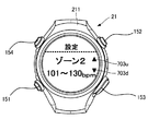
ところで、上述した「ゾーン」は、具体的にはユーザーが次のように設定可能である。図10及び図11は、ユーザーがゾーンを設定する際に表示部120に表示される画面の一例を示す図である。
当該生体情報計測装置1が時刻表示モードのときに操作ボタン151〜154を用いて所定の操作が行われると、表示部120には、図10に示す「設定ゾーン選択画面」が表示される。ユーザーは、数値範囲の設定を所望するゾーンを、当該設定ゾーン選択画面上で選択マーク701を上下させて選択して決定する。選択マーク701の上移動を示すアップマーク703uは第2ボタン152に対応し、選択マーク701の下移動を示すダウンマーク703dは第3ボタン153に対応する。また、選択マーク701を当て嵌めたゾーンを設定対象として決定するには、例えば第1ボタン151を利用する。
By the way, the above-mentioned “zone” can be specifically set by the user as follows. 10 and 11 are diagrams illustrating an example of a screen displayed on the
When a predetermined operation is performed using the
図10に示す設定ゾーン選択画面において、例えばゾーン2が選択されて設定対象として決定された場合、表示部120には、例えば図11に示す数値範囲設定画面が表示される。ユーザーは、操作ボタン151〜154を用いた所定の操作で、当該ゾーン(本例ではゾーン2)の数値範囲を設定する。
When, for example,
図12は、ゾーンの数値範囲の設定例を説明する図である。
図12(A)に示す設定例(通常設定例)は、各ゾーンの数値範囲が互いに重複しないように(排他的に)設定されている例である。すなわち、同図に示す例では、ゾーン1は30〜100bpm、ゾーン2は101〜130bpm、ゾーン3は131〜160bpm、ゾーン4は161〜190bpm、ゾーン5は191〜240bpmの数値範囲に設定されている。
FIG. 12 is a diagram for explaining an example of setting the numerical range of the zone.
The setting example (normal setting example) shown in FIG. 12A is an example in which the numerical ranges of the zones are set so as not to overlap each other (exclusively). That is, in the example shown in the figure, zone 1 is set to 30 to 100 bpm,
図12(B)に示す設定例(重複設定例)は、少なくともつ二以上のゾーン(本例では二つのゾーン)の数値範囲が重複して設定された例である。すなわち、同図に示す例では、ゾーン1は30〜100bpm、ゾーン2は101〜130bpm、ゾーン3は131〜165bpm、ゾーン4は160〜190bpm、ゾーン5は191〜240bpmの数値範囲に設定されている。同図において、網掛けで示されているゾーンが、互いに重複する数値範囲に設定されたゾーンである。
The setting example (duplicate setting example) shown in FIG. 12B is an example in which the numerical value ranges of at least two or more zones (two zones in this example) are set to overlap. That is, in the example shown in the figure, zone 1 is set to a numerical value range of 30 to 100 bpm,
ここで、図12(A)に示す通常設定例に対応するゾーン表示は、上述した図6に示すゾーン表示506である。すなわち、計測モードにおいて当該時点における心拍数が165bpmである場合、この心拍数165が属するゾーン4を示す左から4つ目の円形表示が点灯(同図において黒色表示)される。ユーザーは、このゾーン表示506を視認することで、自身が所望の数値範囲に設定した各ゾーンのいずれに属する心拍数であるかを容易に把握することができる。
Here, the zone display corresponding to the normal setting example shown in FIG. 12A is the
他方、図12(B)に示す重複設定例に対応するゾーン表示は、図13に示すゾーン表示506である。すなわち、図13は、ゾーンの数値範囲が重複設定された場合の、計測モードにおける表示部120の表示例を示す図である。同図に示すように、計測モードにおいて当該時点における心拍数が165bpmである場合、この心拍数165はゾーン3及びゾーン4に属する。従って、ゾーン3を示す左から3つ目の円形表示と、ゾーン4を示す左から4つ目の円形表示とが点灯(同図において黒色表示)される。ユーザーは、このゾーン表示506を視認することで、自身が所望の数値範囲に設定した各ゾーンのいずれに属する心拍数であるかを容易に把握することができる。
このようにゾーンの数値範囲を重複設定することで、例えばランニングの行程における特定の一区間では最も心拍数が多いゾーンを達成しつつ、他の区間では一段階低い心拍数のゾーンに係る数値範囲の上半分の心拍数は許容するといった柔軟な走行プランを実行することが容易となる。
On the other hand, the zone display corresponding to the overlap setting example shown in FIG. 12B is the
By overlapping the numerical value ranges of the zones in this way, for example, while achieving a zone with the highest heart rate in a specific section in the running process, the numerical range related to the heart rate zone one step lower in the other sections It is easy to execute a flexible driving plan that allows the upper half of the heart rate.
なお、従来の生体情報計測装置の構成では、このようにゾーンを設定することはできない。さらに言えば、従来の生体情報計測装置の構成では、ゾーン表示506のように複数のゾーンを個別に表現することができないため、互いに排他的に数値範囲が設定されたゾーンのみにしか対応できない。
In addition, in the structure of the conventional biological information measuring device, a zone cannot be set in this way. Furthermore, in the configuration of the conventional biological information measuring apparatus, since a plurality of zones cannot be individually expressed like the
図14は、ユーザーに警告を知らせる「心拍アラーム」が作動したときの表示部120の表示例を示す図である。「心拍アラーム」とは、ユーザーの心拍数が、警告の対象となる一又は複数のゾーンである「警告ゾーン」に属した場合に、MCU136によって表示部120に図14に示すような警告画面が表示される機能である。心拍アラームが作動したとき、表示部120はユーザーに警告を知らせる警告部として機能する。ここで、「警告ゾーン」は、ユーザーが操作ボタン151〜154を用いて所定の操作を行うことで設定可能である。
なお、心拍アラームが作動したときには、スピーカー(不図示)によって所定の警告音を発してユーザーの注意を喚起してもよいし、振動部129によってユーザーの腕に振動を伝達させてユーザーの注意を喚起してもよい。
図14に示す警告画面の例では、心拍アラームが作動したことを示す警告表示800と、当該時点における心拍数情報507と、警告ゾーンを示す警告ゾーン表示801と、当該警告ゾーンの下限値803d及び上限値803uとが表示部120に表示される。
FIG. 14 is a diagram illustrating a display example of the
When the heartbeat alarm is activated, a predetermined warning sound may be emitted from a speaker (not shown) to alert the user, or the
In the example of the warning screen shown in FIG. 14, a
なお、上述した例ではユーザーの心拍数が警告ゾーンに属したときに心拍アラームが作動する例であるが、逆に、ユーザーの心拍数が所定のゾーン(目標ゾーン)から外れたときに心拍アラームが作動する構成としてもよい。この場合、ユーザーは警告の対象から除外する一又は複数の目標ゾーンを設定し、心拍数が目標ゾーンに属しない場合に、MCU136は、警告を発するように警告部(表示部120、振動部129など)を制御する。上述した警告ゾーンを設定する心拍アラームと、目標ゾーンを設定する心拍アラームとは実質的に等価である。
In the above example, the heart rate alarm is activated when the user's heart rate belongs to the warning zone, but conversely, the heart rate alarm is activated when the user's heart rate deviates from a predetermined zone (target zone). It is good also as composition which operates. In this case, the user sets one or a plurality of target zones to be excluded from the target of warning, and when the heart rate does not belong to the target zone, the
以上説明したように、本発明の一実施形態によれば、各ゾーンに対応する心拍数の数値範囲を、複数のゾーンで重複して設定可能とすると共に、このように設定されたゾーンをユーザーに適切に提示することが可能な生体情報計測装置を提供することができる。
なお、以上のように本実施形態について詳細に説明したが、本発明の新規事項および効果から実体的に逸脱しない多くの変形が可能であることは当業者には容易に理解できるであろう。従って、このような変形例はすべて本発明の範囲に含まれるものとする。例えば、明細書又は図面において、少なくとも一度、より広義または同義な異なる用語と共に記載された用語は、明細書又は図面のいかなる箇所においても、その異なる用語に置き換えることができる。また生体情報計測装置の構成、動作も本実施形態で説明したものに限定されず、種々の変形実施が可能である。
As described above, according to an embodiment of the present invention, it is possible to set the heart rate numerical range corresponding to each zone in a plurality of zones, and to set the zone set in this way as a user. It is possible to provide a biological information measuring device that can be presented appropriately.
Although the present embodiment has been described in detail as described above, it will be easily understood by those skilled in the art that many modifications can be made without departing from the novel matters and effects of the present invention. Accordingly, all such modifications are intended to be included in the scope of the present invention. For example, a term described at least once together with a different term having a broader meaning or the same meaning in the specification or the drawings can be replaced with the different term in any part of the specification or the drawings. Further, the configuration and operation of the biological information measuring device are not limited to those described in the present embodiment, and various modifications can be made.
[第1変形例]
上述した一実施形態に係る生体情報計測装置1において、図8に示すフローチャートのステップS103の処理内容を次のように変更してもよい。
すなわち、ステップS103からステップS104の処理へ進んで時刻表示モードに移行する条件を、「第1ボタン151の短押し操作」とする代わりに、「例えば1分間などの所定時間の経過」としてもよい。
この場合、MCU136は、ステップS103において所定時間が経過したか否かを判定する。判定結果が肯定の場合にはステップS104の処理へ進む。なお、このように所定時間の経過でステップS104の処理へ進む構成としつつ、当該所定時間の経過前であれば第1ボタン151の短押し操作でステップS104の処理へ進むように構成してもよい。
[First Modification]
In the biological information measuring apparatus 1 according to the embodiment described above, the processing content of step S103 in the flowchart shown in FIG. 8 may be changed as follows.
That is, the condition for proceeding from step S103 to step S104 and shifting to the time display mode may be “elapse of a predetermined time such as 1 minute” instead of “short pressing operation of the
In this case, the
[第2変形例]
上述した一実施形態に係る生体情報計測装置1において、図8に示すフローチャートのステップS107の処理内容を次のように変更してもよい。
すなわち、ステップS107からステップS104の処理へ進んで時刻表示モードに移行する条件を、「計測初期状態であって、且つ、第1ボタン151又は第2ボタン152の長押し操作」とする代わりに、「例えば1時間などの所定時間の経過」としてもよい。
この場合、MCU136は、ステップS107において所定時間が経過したか否かを判定する。判定結果が肯定の場合にはステップS104の処理へ進む。なお、このように所定時間の経過でステップS104の処理へ進む構成としつつ、当該所定時間の経過前であれば、計測初期状態での第1ボタン151又は第2ボタン152の長押し操作でステップS104の処理へ進むように構成してもよい。
[Second Modification]
In the biological information measuring apparatus 1 according to the embodiment described above, the processing content of step S107 in the flowchart shown in FIG. 8 may be changed as follows.
That is, instead of setting the condition for proceeding from step S107 to step S104 and shifting to the time display mode as "measurement initial state and long press operation of
In this case, the
[応用例]
上述した各モードの他に、アンテナ130及び脈波センサー部160を、それぞれ個別に動作状態/停止状態に設定できる第4のモードを加えてもよい。
駆動時間は動作状況によっても変化する。例えば、GPS(アンテナ130)による毎秒の測位、及び脈波センサー部160による脈波情報の計測を同時に行った場合、生体情報計測装置1は、20時間の駆動が可能である。また、脈波センサー部160を停止状態とし、且つ、アンテナ130を動作状態としてGPSによる毎秒測位を行った場合、生体情報検出装置1は24時間の駆動が可能である。さらには、アンテナ130を停止状態とし、脈波センサー部160の計測を行った場合、生体情報検出装置1は60時間の駆動が可能である。
[Application example]
In addition to the above-described modes, a fourth mode in which the
The driving time also varies depending on the operating conditions. For example, when positioning by GPS (antenna 130) per second and measurement of pulse wave information by the pulse
1…生体情報計測装置、30…アンテナ、40…回路基板、42…パネル枠、44…回路ケース、120…表示部、124…電源回路、128…二次電池、129…振動部、130…アンテナ、135…無線通信部、137…ライト、138…加速度センサー、139…水晶発振回路、141…リセット回路、142…アダプタ、151…第1操作ボタン、152…第2操作ボタン、153…第3操作ボタン、154…第4操作ボタン、159…記憶部、160…脈波センサー部、211…胴部、212…ガラス板、221…透光部、2211…検出窓、222…遮光部、311…発光部、451…電池表示、453…衛星表示、455,455f…ハート表示、504…日付情報、505…時刻表示、506…ゾーン表示、507…心拍数情報、507p…心拍準備情報、509…ラップペース情報、511…累積移動距離情報。
DESCRIPTION OF SYMBOLS 1 ... Biological information measuring device, 30 ... Antenna, 40 ... Circuit board, 42 ... Panel frame, 44 ... Circuit case, 120 ... Display part, 124 ... Power supply circuit, 128 ... Secondary battery, 129 ... Vibrating part, 130 ...
Claims (7)
前記心拍数情報に基づいて、生体の心拍数が予め定められた複数の心拍範囲のうちいずれの心拍範囲に属するかを特定する特定部と、
前記複数の心拍範囲の各々に対応して設けられた表示領域と、
前記特定部で特定された心拍範囲に対応する表示領域において、生体の心拍数が当該心拍範囲に属することを表示するように制御する制御部と、
を備える生体情報計測装置。 A heart rate information generating unit for generating heart rate information indicating a heart rate of a living body;
Based on the heart rate information, a specifying unit that specifies which heart rate range of a plurality of predetermined heart rate ranges belong to a living body,
A display area provided corresponding to each of the plurality of heartbeat ranges;
A control unit that controls to display that the heart rate of the living body belongs to the heart rate range in a display region corresponding to the heart rate range specified by the specifying unit;
A biological information measuring device comprising:
前記操作信号にもとづいて、前記複数の心拍範囲の各々について、下限の心拍数と上限の心拍数とを設定可能な設定部とを備え、
前記特定部は、前記複数の心拍範囲の各々について、前記設定部によって設定された下限の心拍数及び上限の心拍数を参照して、生体の心拍数がいずれの心拍範囲に属するかを特定する、
請求項1に記載の生体情報計測装置。 An operation unit that outputs an operation signal according to a human input operation;
A setting unit capable of setting a lower limit heart rate and an upper limit heart rate for each of the plurality of heart rate ranges based on the operation signal;
The identifying unit refers to the lower limit heart rate and the upper limit heart rate set by the setting unit for each of the plurality of heart rate ranges, and identifies to which heart rate range the heart rate of the living body belongs. ,
The biological information measuring device according to claim 1.
前記第1の心拍範囲に対応する表示領域が第1表示領域、前記第2の心拍範囲に対応する表示領域が第2表示領域であり、
前記第1の心拍範囲の下限の心拍数を第1下限心拍数、前記第1の心拍範囲の上限の心拍数を第1上限心拍数、及び前記第2の心拍範囲の下限の心拍数を第2下限心拍数、前記第2の心拍範囲の上限の心拍数を第2上限心拍数とし、
前記第2下限心拍数は、前記第1下限心拍数より大きく、且つ前記第1上限心拍数より小さいとしたとき、
前記心拍数情報が示す心拍数が、前記第2下限心拍数より大きく、且つ前記第1上限心拍数より小さい場合、
前記特定部は、生体の心拍数が、前記第1の心拍範囲及び前記第2の心拍範囲に属すると特定し、
前記制御部は、前記第1表示部において生体の心拍数が前記第1の心拍範囲に属すること表示するように制御し、且つ前記第2表示部において生体の心拍数が前記第2の心拍範囲に属すること表示するように制御する、
請求項2に記載の生体情報計測装置。 The plurality of heart rate ranges include a first heart rate range and a second heart rate range;
A display area corresponding to the first heart rate range is a first display area, and a display area corresponding to the second heart rate range is a second display area;
The lower heart rate of the first heart rate range is the first lower heart rate, the upper heart rate of the first heart rate range is the first upper heart rate, and the lower heart rate of the second heart rate range is the first heart rate. 2 lower limit heart rate, the upper limit heart rate of the second heart rate range as the second upper limit heart rate,
When the second lower limit heart rate is larger than the first lower limit heart rate and smaller than the first upper limit heart rate,
When the heart rate indicated by the heart rate information is larger than the second lower limit heart rate and smaller than the first upper limit heart rate,
The specifying unit specifies that the heart rate of the living body belongs to the first heart rate range and the second heart rate range;
The control unit controls the first display unit to display that the heart rate of the living body belongs to the first heart rate range, and the second display unit displays the heart rate of the living body in the second heart rate range. Control to show that it belongs to,
The biological information measuring device according to claim 2.
請求項1乃至3のうちいずれか1項に記載の生体情報計測装置。 The plurality of display areas are areas allocated to a screen of a display unit that displays an image, and are arranged in the 12 o'clock direction of the clock among the screens.
The biological information measuring device according to any one of claims 1 to 3.
前記設定部は、前記操作信号に基づいて、警告の対象となる一又は複数の心拍範囲である警告心拍範囲を設定可能であり、
前記制御部は、前記心拍情報の示す心拍数が前記警告心拍範囲に属する場合に、警告を発するように前記警告部を制御する、
請求項1乃至4のうちいずれか1項に記載の生体情報計測装置。 A warning section is provided to notify the user of the warning,
The setting unit can set a warning heart rate range that is one or a plurality of heart rate ranges to be warned based on the operation signal,
The control unit controls the warning unit to issue a warning when the heart rate indicated by the heart rate information belongs to the warning heart rate range.
The biological information measuring device according to any one of claims 1 to 4.
前記設定部は、前記操作信号に基づいて、警告の対象から除外する一又は複数の心拍範囲である目標心拍範囲を設定可能であり、
前記制御部は、前記心拍情報の示す心拍数が前記目標心拍範囲に属しない場合に、警告を発するように前記警告部を制御する、
請求項1乃至4のうちいずれか1項に記載の生体情報計測装置。 A warning section is provided to notify the user of the warning,
The setting unit is capable of setting a target heart rate range that is one or a plurality of heart rate ranges to be excluded from warning targets based on the operation signal,
The control unit controls the warning unit to issue a warning when the heart rate indicated by the heart rate information does not belong to the target heart rate range.
The biological information measuring device according to any one of claims 1 to 4.
前記設定部は、前記操作信号に基づいて、警告の対象となる一又は複数の心拍範囲である警告心拍範囲を設定可能であり、
前記制御部は、前記心拍情報の示す心拍数が前記警告心拍範囲に属する場合に、前記表示部に前記複数の表示領域を設定する代わりに、警告を表示する、
請求項1乃至3のうちいずれか1項に記載の生体情報計測装置。
The plurality of display areas are areas allocated to a screen of a display unit that displays an image,
The setting unit can set a warning heart rate range that is one or a plurality of heart rate ranges to be warned based on the operation signal,
When the heart rate indicated by the heart rate information belongs to the warning heart rate range, the control unit displays a warning instead of setting the plurality of display areas on the display unit.
The biological information measuring device according to any one of claims 1 to 3.
Priority Applications (3)
| Application Number | Priority Date | Filing Date | Title |
|---|---|---|---|
| JP2014173295A JP2016047154A (en) | 2014-08-27 | 2014-08-27 | Biological information measurement device |
| CN201510490427.9A CN105380629A (en) | 2014-08-27 | 2015-08-11 | Biological information measuring device |
| US14/833,374 US9737221B2 (en) | 2014-08-27 | 2015-08-24 | Biological information measuring device |
Applications Claiming Priority (1)
| Application Number | Priority Date | Filing Date | Title |
|---|---|---|---|
| JP2014173295A JP2016047154A (en) | 2014-08-27 | 2014-08-27 | Biological information measurement device |
Publications (2)
| Publication Number | Publication Date |
|---|---|
| JP2016047154A true JP2016047154A (en) | 2016-04-07 |
| JP2016047154A5 JP2016047154A5 (en) | 2017-09-28 |
Family
ID=55401124
Family Applications (1)
| Application Number | Title | Priority Date | Filing Date |
|---|---|---|---|
| JP2014173295A Withdrawn JP2016047154A (en) | 2014-08-27 | 2014-08-27 | Biological information measurement device |
Country Status (3)
| Country | Link |
|---|---|
| US (1) | US9737221B2 (en) |
| JP (1) | JP2016047154A (en) |
| CN (1) | CN105380629A (en) |
Families Citing this family (25)
| Publication number | Priority date | Publication date | Assignee | Title |
|---|---|---|---|---|
| CN110251080B (en) | 2014-02-11 | 2022-04-26 | 苹果公司 | Detecting a limb wearing a wearable electronic device |
| US10827268B2 (en) | 2014-02-11 | 2020-11-03 | Apple Inc. | Detecting an installation position of a wearable electronic device |
| US10092197B2 (en) * | 2014-08-27 | 2018-10-09 | Apple Inc. | Reflective surfaces for PPG signal detection |
| US9723997B1 (en) | 2014-09-26 | 2017-08-08 | Apple Inc. | Electronic device that computes health data |
| US10537284B1 (en) | 2015-09-30 | 2020-01-21 | Apple Inc. | Enhanced sensor signal collection and reflection of reflected and/or scattered light |
| EP3515301A4 (en) * | 2016-09-16 | 2021-07-07 | Honeywell Safety Products USA, Inc. | Systems, devices, and methods for biometric assessment |
| WO2018096631A1 (en) | 2016-11-24 | 2018-05-31 | オリンパス株式会社 | Data processing device, computer readable medium, data processing method, and program |
| US10845955B2 (en) | 2017-05-15 | 2020-11-24 | Apple Inc. | Displaying a scrollable list of affordances associated with physical activities |
| JP2019027880A (en) * | 2017-07-28 | 2019-02-21 | セイコーエプソン株式会社 | Wearable apparatus |
| ES2963483T3 (en) | 2017-09-05 | 2024-03-27 | Apple Inc | Wearable electronic device with electrodes to detect biological parameters |
| EP3459447A3 (en) | 2017-09-26 | 2019-07-10 | Apple Inc. | Optical sensor subsystem adjacent a cover of an electronic device housing |
| DK179980B1 (en) * | 2018-03-12 | 2019-11-27 | Apple Inc. | User interfaces for health monitoring |
| DK179992B1 (en) | 2018-05-07 | 2020-01-14 | Apple Inc. | Visning af brugergrænseflader associeret med fysiske aktiviteter |
| US11317833B2 (en) | 2018-05-07 | 2022-05-03 | Apple Inc. | Displaying user interfaces associated with physical activities |
| CN109819110B (en) * | 2019-01-18 | 2021-05-04 | Oppo广东移动通信有限公司 | Motion control method and related device |
| EP4167830A1 (en) * | 2019-05-05 | 2023-04-26 | Rehn, Annabelle | Smart band for alerting during emergencies |
| DK201970534A1 (en) | 2019-06-01 | 2021-02-16 | Apple Inc | User interfaces for monitoring noise exposure levels |
| US11152100B2 (en) | 2019-06-01 | 2021-10-19 | Apple Inc. | Health application user interfaces |
| US11209957B2 (en) | 2019-06-01 | 2021-12-28 | Apple Inc. | User interfaces for cycle tracking |
| US11234077B2 (en) | 2019-06-01 | 2022-01-25 | Apple Inc. | User interfaces for managing audio exposure |
| US11228835B2 (en) | 2019-06-01 | 2022-01-18 | Apple Inc. | User interfaces for managing audio exposure |
| GB2584492B (en) | 2019-06-07 | 2021-08-18 | Prevayl Ltd | Method, garment and system |
| CN114706505A (en) | 2019-09-09 | 2022-07-05 | 苹果公司 | Research user interface |
| DK181037B1 (en) | 2020-06-02 | 2022-10-10 | Apple Inc | User interfaces for health applications |
| US11698710B2 (en) | 2020-08-31 | 2023-07-11 | Apple Inc. | User interfaces for logging user activities |
Citations (2)
| Publication number | Priority date | Publication date | Assignee | Title |
|---|---|---|---|---|
| JPS5979108U (en) * | 1982-11-19 | 1984-05-29 | 小山内 恒 | pulse meter |
| JPH05220120A (en) * | 1992-02-18 | 1993-08-31 | Casio Comput Co Ltd | Kinetic intensity display device |
Family Cites Families (8)
| Publication number | Priority date | Publication date | Assignee | Title |
|---|---|---|---|---|
| US6149602A (en) * | 1996-09-10 | 2000-11-21 | Arcelus; Almudena | User-worn electrocardiogram viewer device |
| FI113402B (en) * | 2000-10-06 | 2004-04-15 | Polar Electro Oy | wrist device |
| JP3852352B2 (en) | 2002-03-14 | 2006-11-29 | セイコーエプソン株式会社 | Life activity measurement device |
| US8504145B2 (en) * | 2006-12-11 | 2013-08-06 | Seiko Epson Corporation | Biometric information processing device, biometric information processing method, and control program |
| US8092381B2 (en) * | 2007-05-31 | 2012-01-10 | Heart Zones Usa | Threshold training system |
| CN103955131B (en) * | 2009-04-26 | 2017-04-12 | 耐克创新有限合伙公司 | GPS features and functionality in an athletic watch system |
| US8200323B2 (en) * | 2009-05-18 | 2012-06-12 | Adidas Ag | Program products, methods, and systems for providing fitness monitoring services |
| US20150209615A1 (en) * | 2014-01-27 | 2015-07-30 | Sally Edwards | Zoning Method of Processing Threshold and Metabolic and Heart Rate Training Data and Sensors and Apparatus for Displaying the Same |
-
2014
- 2014-08-27 JP JP2014173295A patent/JP2016047154A/en not_active Withdrawn
-
2015
- 2015-08-11 CN CN201510490427.9A patent/CN105380629A/en active Pending
- 2015-08-24 US US14/833,374 patent/US9737221B2/en active Active
Patent Citations (2)
| Publication number | Priority date | Publication date | Assignee | Title |
|---|---|---|---|---|
| JPS5979108U (en) * | 1982-11-19 | 1984-05-29 | 小山内 恒 | pulse meter |
| JPH05220120A (en) * | 1992-02-18 | 1993-08-31 | Casio Comput Co Ltd | Kinetic intensity display device |
Also Published As
| Publication number | Publication date |
|---|---|
| US20160058313A1 (en) | 2016-03-03 |
| US9737221B2 (en) | 2017-08-22 |
| CN105380629A (en) | 2016-03-09 |
Similar Documents
| Publication | Publication Date | Title |
|---|---|---|
| JP2016047154A (en) | Biological information measurement device | |
| WO2016031193A1 (en) | Biological information measuring device | |
| US10172529B2 (en) | Systems and methods for detecting physiological information of a user | |
| US11963590B2 (en) | Ring-type wearable device | |
| US7778118B2 (en) | Watch device having touch-bezel user interface | |
| EP3344121B1 (en) | Display arrangement for watch case | |
| JP6476656B2 (en) | Biological information detection device | |
| US20140221854A1 (en) | Measuring device, including a heart rate sensor, configured to be worn on the wrist of a user | |
| US6745069B2 (en) | Electronic wrist-worn device and method of controlling the same | |
| JP5998780B2 (en) | Biometric information notification device, biometric information notification method, and biometric information notification program | |
| JP2018529416A (en) | Heart rate monitor | |
| CN106959769B (en) | Function driving device and function driving method | |
| JP2016047086A (en) | Biological information detector | |
| US20130187786A1 (en) | Goggles, system and method for providing feedback | |
| JP2016016203A (en) | Biological information detection device | |
| US20160041531A1 (en) | Biofeedback watches | |
| US20180321640A1 (en) | Wearable apparatus and display method | |
| JP7098982B2 (en) | Portable electronic devices | |
| JP5790694B2 (en) | Biological information processing method and biological information processing apparatus | |
| JP5239370B2 (en) | Biological information processing apparatus and biological information processing method | |
| CN202458381U (en) | Finger-clamping blood oxygen saturation measuring device having the capability of automatic power on/off and provided with pedometer | |
| JP5071148B2 (en) | Biological information processing apparatus and control method of biological information processing apparatus | |
| JP2015161542A (en) | Notification device and control method | |
| JP2017127458A (en) | Athletic performance measuring device | |
| JP2019170773A (en) | Biological information measuring apparatus and biological information processing method |
Legal Events
| Date | Code | Title | Description |
|---|---|---|---|
| A521 | Request for written amendment filed |
Free format text: JAPANESE INTERMEDIATE CODE: A523 Effective date: 20170816 |
|
| A621 | Written request for application examination |
Free format text: JAPANESE INTERMEDIATE CODE: A621 Effective date: 20170816 |
|
| A977 | Report on retrieval |
Free format text: JAPANESE INTERMEDIATE CODE: A971007 Effective date: 20180417 |
|
| A131 | Notification of reasons for refusal |
Free format text: JAPANESE INTERMEDIATE CODE: A131 Effective date: 20180605 |
|
| A761 | Written withdrawal of application |
Free format text: JAPANESE INTERMEDIATE CODE: A761 Effective date: 20180711 |