JP3848637B2 - Ultrasonic bonding equipment - Google Patents
Ultrasonic bonding equipment Download PDFInfo
- Publication number
- JP3848637B2 JP3848637B2 JP2003127739A JP2003127739A JP3848637B2 JP 3848637 B2 JP3848637 B2 JP 3848637B2 JP 2003127739 A JP2003127739 A JP 2003127739A JP 2003127739 A JP2003127739 A JP 2003127739A JP 3848637 B2 JP3848637 B2 JP 3848637B2
- Authority
- JP
- Japan
- Prior art keywords
- ultrasonic
- ultrasonic horn
- stage
- horn
- slide
- Prior art date
- Legal status (The legal status is an assumption and is not a legal conclusion. Google has not performed a legal analysis and makes no representation as to the accuracy of the status listed.)
- Expired - Lifetime
Links
Images


Classifications
-
- H—ELECTRICITY
- H01—ELECTRIC ELEMENTS
- H01L—SEMICONDUCTOR DEVICES NOT COVERED BY CLASS H10
- H01L2224/00—Indexing scheme for arrangements for connecting or disconnecting semiconductor or solid-state bodies and methods related thereto as covered by H01L24/00
- H01L2224/01—Means for bonding being attached to, or being formed on, the surface to be connected, e.g. chip-to-package, die-attach, "first-level" interconnects; Manufacturing methods related thereto
- H01L2224/10—Bump connectors; Manufacturing methods related thereto
- H01L2224/15—Structure, shape, material or disposition of the bump connectors after the connecting process
- H01L2224/16—Structure, shape, material or disposition of the bump connectors after the connecting process of an individual bump connector
-
- H—ELECTRICITY
- H01—ELECTRIC ELEMENTS
- H01L—SEMICONDUCTOR DEVICES NOT COVERED BY CLASS H10
- H01L2224/00—Indexing scheme for arrangements for connecting or disconnecting semiconductor or solid-state bodies and methods related thereto as covered by H01L24/00
- H01L2224/74—Apparatus for manufacturing arrangements for connecting or disconnecting semiconductor or solid-state bodies and for methods related thereto
- H01L2224/75—Apparatus for connecting with bump connectors or layer connectors
- H01L2224/759—Means for monitoring the connection process
Description
【0001】
【発明の属する技術分野】
本発明は、横振動方式の超音波ホーンを使用し、例えば、集積回路のベアチップのバンプを直接プリント基板のランド部に超音波で接合する超音波接合装置に関し、特に、超音波ホーンの保持構造を改良した超音波接合装置に関するものである。
【0002】
【従来の技術】
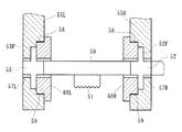
従来の超音波接合装置は、図6および図7に示すように、超音波の予め定めた少なくとも周波数の1波長の長さを有し、この周波数における共振時に、少なくとも両端および中央に、長手方向へ3つの最大振動振幅点を有する超音波ホーン50と、この超音波ホーン50の中央の最大振動振幅点に超音波ホーンの外側に突出し被接合部材W1、W2と係合する係合用チップ51と、超音波ホーン50の両端の最大振動振幅点に同軸上に連結され、超音波の周波数の半波調の長さを有し、その両端に最大振動振幅点を、外部中央にノーダルポイント(波長の振動振幅のゼロ点)Pn、Pnを有するブースタ52、53と、これらブースタ52、53の一方に同軸上に連結された超音波振動子54と、各ブースタ52、53における外部ノーダルポイントPn、Pnを機械的なクランプ手段でクランプした支持部材55R、55Lと、これらの支持部材55R、55Lと被接合部材W1、W2を載置した受台56とを相対的に移動せしめて被接合部材W1、W2に係合用チップ51を加圧せしめる加圧手段とを備えている。
【0003】
支持部材55R、55Lには段付穴57R、57Lが形成されていると共に、この段付穴57R、57Lの大径部の内周面には雌ねじ58、58が形成されている。そして、支持部材52、53の段付穴57R、57Lにブースタ52、53を挿入し、外周面に雄ねじ59、59が形成された締付部材60R、60Lを螺合して締付けることにより、ブースタ52、53の凸部52F、53Fが支持部材55R、55Lに強固にクランプされている。
【0004】
ここで、ブースタ52、53が支持された支持部材55R、55Lを加圧手段で振動方向と直交した方向へ移動させて超音波ホーン50に配設された係合用チップ51を被接合部材W1、W2に接触させると共に、加圧しながら加振して超音波接合が行なわれる。この時、超音波ホーン50を挟持する各ブースタ52、53は、ノーダルポイントPn、Pnで支持部材55R、55Lに機械的に強固に連結されているから、接合時に被接合部材W1、W2と超音波ホーン50の付着が抑制される。したがって、超音波ホーン50の寿命が伸び、超音波のエネルギーロスが低減される(例えば、特許文献1参照。)。
【0005】
【特許文献1】
特許第2583398号公報(第3、4頁、第2、3図)
【0006】
【発明が解決しようとする課題】
しかしながら、こうした従来の超音波接合装置では、予め定めた超音波の周波数における1波長の長さを有する超音波ホーン50を、超音波の周波数の半波調の長さを有する一対のブースタ52、53で挟持し、これら各ブースタ52、53におけるノーダルポイントPn、Pnで支持部材55R、55Lに対して機械的に連結しているから、超音波振動子54で加振する振動体(超音波ホーン50とブースタ52、53)は、予め定めた超音波の周波数の少なくとも2波長の長さとなる。これでは振動体の重量が嵩み、ひいてはこの振動体を含む可動体の重量が嵩んで位置決め精度が低下すると共に、位置決め制御に時間がかかり、接合するための作業時間を短縮してチップ部品を低コスト化するには限界があった。
【0007】
本発明は、このような事情に鑑みてなされたもので、超音波振動を利用した半導体部品等の超音波接合装置において、超音波ホーンを含む振動体の重量を低減し、位置決め精度を向上させると共に、位置決め制御を容易にして接合作業時間を抑制した超音波接合装置を提供することを目的としている。
【0010】
【課題を解決するための手段】
係る目的を達成すべく、本発明のうち請求項1に記載の発明は、横振動方式の超音波ホーンを利用して電子部品に水平方向の超音波振動を付与することで溶融接合し実装する超音波接合装置において、超音波の周波数の1波長分の長さに予め設定され、その両端部および長手方向中央部に最大振動振幅点を有する超音波ホーンと、この超音波ホーンの長手方向中央の最大振動振幅点に設けられた接合作用部と、この接合作用部と相対する上面に固着された摺動部と、前記超音波ホーンの一端部に同軸上に連結され、当該超音波ホーンを横振動させる超音波振動子と、前記超音波ホーンの2つのノーダルポイントを固定ボルトを介して着脱自在に固定した支持部材とを備え、前記摺動部を摩擦係数の小さい部材で構成し、前記超音波ホーンの加圧受け部とした。
【0011】
このように、前記摺動部を摩擦係数の小さい部材で構成し、前記超音波ホーンの加圧受け部とすることにより、接合性を高め、効果的に接合作業を行うことができる。
【0012】
好ましくは、請求項2に記載の発明のように、前記加圧手段は、静圧軸受を介してガイドバーで軸方向移動自在に案内されたZステージと、このZステージを進退自在に位置決めするZスライドとを備え、このZスライドにモータを装着し、このモータの回転をボールねじによって前記Zステージを直線運動に変換するようにすれば、Zステージのスティックスリップを可及的に抑制することができ、超音波ホーンのZ軸制御精度が向上すると共に、ボールねじの直線運動をスムーズに行うことができ、位置決め精度を格段に向上させることができる。
【0013】
また、請求項3に記載の発明は、前記超音波ホーンの長手方向中央部の最大振動振幅点で、その上面に突出した摺動部を設けると共に、前記Zステージの下端部にドグを突設し、このドグに対峙する圧力検出器を介して前記摺動部を加圧したので、加圧力の精度を向上させると共に、接合強度を低下させることなく安定した超音波接合を行うことができ、接合部の品質向上を図ることができる。
【0014】
また、請求項4に記載の発明は、前記支持部材は、静圧軸受を介して前記ガイドバーで軸方向移動自在に案内されているので、超音波ホーンを傾き等なく、安定して精度良く支持することができ、加圧力の精度を向上させる。
【0015】
好ましくは、請求項5に記載の発明のように、前記支持部材が前記Zステージに対してばねで吊下げられていれば、支持部材等の重量が超音波ホーンにかかることはなく、超音波ホーンを含む振動体の重量をさらに低減することができるので、位置決め制御が容易となり接合作業時間を短縮することができる。
【0016】
【発明の実施の形態】
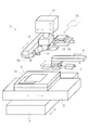
以下、本発明の実施形態を図面に基いて詳細に説明する。図1は、本発明に係る超音波接合装置の実施形態を示す概略図である。本実施形態では、プリント基板15にベアチップ(半導体チップ)14を実装するフリップチップボンダーを例として説明する。このフリップチップボンダー1は、基台上に配設されたY1スライド2、このY1スライド2に載置されたX1スライド3、このX1スライド3に設けられた基板ステージ4、Y2スライド5とX2スライド6とで支持されたベアチップ用カメラ7、Y3スライド8で支持されたボンディングコレット9、X3スライド10、Zスライド11で支持された超音波ホーン12、ベアチップ位置決めステージ13、および図示しないトレーステージと制御用コンピュータを備えている。トレーステージは上下動自在に配設され、ベアチップ14がその電極形成面を上に向けて多数収容されている。
【0017】
Y1スライド2、X1スライド3は、2つのACサーボモータの回転をボールねじ機構(図示せず)で直線方向に変換し、水平面内で直交する2方向に移動可能である。X1スライド3上には基板ステージ4が設けられ、図示しない移載手段によりプリント基板15が1枚ずつ移載される。移載されたプリント基板15は、基板ステージ4上で反りや歪みが矯正され、図示しないヒータにて予加熱される。
【0018】
ベアチップ用カメラ7は、例えばCCDカメラ等の上下2視野小型カメラからなり、基板ステージ4の上方で進退自在に配設されている。ベアチップ14をプリント基板15の手前でベアチップ位置決めステージ13に表裏を反転させて降ろし、Y3スライド8とX3スライド10で位置決めした後に、Y3スライド8に設けられたボンディングコレット9でベアチップ14を保持してプリント基板15上に載置する。このボンディングコレット9は、ベアチップ14をエアで吸着保持する吸着ノズル9aを有し、ベアチップ14の形状やサイズに応じて適宜交換自在となっている。Y2スライド5、X2スライド6、Y3スライド8、X3スライド10は、それぞれ2つのACサーボモータの回転をボールねじ機構(図示せず)で直線方向に変換し、水平面内で直交する2方向に移動可能である。
【0019】
基板ステージ4上に位置決めされたプリント基板15と、このプリント基板15に位置決めされたベアチップ14の上方に超音波ホーン12がZスライド11に支持されて下降し、所定の位置で停止する。この超音波ホーン12の先端部に、ヘッド回転中心と同軸芯になるようにバキューム孔(図示せず)を形成し、ベアチップ14を吸着保持する。バキューム孔はここで、キーボード、CRTを備えた制御用コンピュータは、このCRTの表示画面を見ながらキーボードから入力されるベアチップ14の種類等の情報パラメータと、その制御用コンピュータに内蔵されたプログラムにしたがって、フリップチップボンダー1の各部の動作を制御する。また、ベアチップ用カメラ7の撮影画像を画像処理し、その結果からボンディングコレット9で移送中のベアチップ14とプリント基板15との相対位置を確認する。
【0020】
図2は、本発明に係るフリップチップボンダー1におけるZスライドの実施形態を示す一部を断面した正面図である。このZスライド11は、ACサーボモータ16と、このモータ16のモータ軸16aにカップリング17を介して連結されたボールねじ軸18aと、このボールねじ軸18aに外嵌されたナット18bと、ナット18bを固着するZステージ19とを備えている。ボールねじ軸18aの外周面およびナット18bの内周面には螺旋状のねじ溝(図示せず)が形成され、これらねじ溝で形成されるボール転走路に多数のボール(図示せず)を転動自在に収容した、所謂ボールねじ18を構成している。このボールねじ18によってモータ16の回転をZ軸方向の直線運動に変換している。
【0021】
ボールねじ軸18aは、ハウジング20に対して転がり軸受21を介して回転自在に、かつ軸方向移動不可に支承されている。一方、ナット18bはZステージ19に固着され、回転不可に、かつ軸方向移動自在に配設されている。
【0022】
Zステージ19は後述する静圧軸受24を介して一対のガイドバー25に対して軸方向移動自在に支持されている。このZステージ19の下端部には、支持部材26が配設されている。この支持部材26は、静圧軸受24を介して一対のガイドバー25に対して軸方向移動自在に支持されている。これにより、超音波ホーン12を傾き等なく、安定して精度良く支持することができ、加圧力の精度を向上させることができる。
【0023】
超音波ホーン12はこの支持部材26に脱着可能に装着され、支持部材26は、一対のコイルばね27によりZステージ19に吊下げられている。したがって、支持部材26の自重はキャンセルされ、超音波振動子32で加振する振動体は、実質的に超音波ホーン12のみとなり、振動体の重量が格段に低減される。
【0024】
Zステージ19の下端部にはドグ28が突設され、このドグ28に対峙してロードセル29が配設されている。このロードセル29によって、超音波ホーン12の加圧力を検出することができる。そして、このロードセル29の出力信号に基き荷重制御が行なわれる。
【0025】
超音波ホーン12は矩形断面に形成され、その両端部および長手方向中央部に最大振動振幅点を有し、両端から略1/4の内部の点にノーダルポイントPnを有すると共に、超音波の周波数の1波長分の長さに予め設定されている(図4参照)。また、超音波ホーン12は、その中央部の最大振動振幅点で、上面に突出した摺動部12a、下面に突出した接合作用部12bを有している。そして、前述したドグ28に対峙する圧力検出器29を介して摺動部12a、すなわち超音波ホーン12の長手方向中央部を加圧する。これにより、加圧力の精度を向上させると共に、接合強度を低下させることなく安定した超音波接合を行うことができ、接合部の品質向上を図ることができる。なお、摺動部12aおよび接合作用部12bの少なくとも表面は、超硬合金や超硬材をバインダとするダイヤ合金等の耐摩耗性に富み、摩擦係数の小さい材質で形成されている。これにより、耐久性を向上させると共に、接合性を向上させてことができる。また、接合作用部12bにはベアチップ14を吸着するための吸引孔(図示せず)が形成されている。
【0026】
超音波ホーン12は一対の固定ボルト30を介して支持部材26に締結されているが、図3に示すように、その固定部はノーダルポイントPnに設定されている。この超音波ホーン12の内部のノーダルポイントPn位置には上下方向に固定ボルト30の外径より大径に挿入孔31形成されている。この挿入孔31の中央、すなわち、超音波ホーン12の断面中央のノーダルポイントPnには雌ねじ31aが形成され、この雌ねじ31に固定ボルト30を螺合することにより、超音波ホーン12は着脱可能に支持部材26に締結することができる。なお、雌ねじ31に変え、内部のノーダルポイントPnに固定ボルト30を嵌挿し、固定ナット(図示せず)で締結しても良い。ここで、超音波ホーン12の材質としては、アルミ合金、黄銅、ステンレス鋼、チタン合金等を例示することができる。
【0027】
超音波ホーン12の一端部には同軸上に超音波振動子32が連結されている。この超音波振動子32は、図示しない超音波発生器より電力が供給され、所定の周波数からなる縦波の超音波を発生して出力する電気エネルギーを機械エネルギーに変換する圧電素子あるいは磁歪素子等のようなエネルギー変換器である。前述したように、超音波ホーン12のノーダルポイントPnを固定ボルト30を介して支持部材26に固定し、超音波ホーン12の接合作用部12bにベアチップ14を吸着した状態で、超音波ホーン12の長手方向に超音波振動を付与すると共に、モータ16を駆動させてボールねじ18を介してZステージ19を下降させて超音波ホーン12を下方に移動させる。すると、受台33上に載置されたプリント基板15とベアチップ14とが接触し、両者が加圧される。このように、プリント基板15とベアチップ14を加圧させながら超音波振動を付与することにより、接触面の酸化膜が排除されて活性化した金属面が露出し、摩擦による境界部での局部温度上昇が加わって、活性原子間の距離が近付き金属接合が行なわれる。
【0028】
図5は静圧軸受24の実施形態を示す断面斜視図である。この静圧軸受24は、多孔質燒結合金からなる軸受部36と、この軸受部36に外嵌されたバックメタル37とから構成されている。このバックメタル37の内周面には、環状の吸気溝37aが形成され、この吸気溝37aを連通する吸気室37bを通して吸気口37cに開口している。吸気口37cは図示しない吸気管を介してエア供給源に連通している。
【0029】
軸受部36は、銅系の燒結金属と黒鉛等の固体潤滑材およびこれらを結合させるバインダーからなり、所定の圧力で金型内で成形し、その後熱処理されている。粉体の粒子サイズや成形圧力によって所望のサイズの気孔を形成することができ、さらに軸受面となる内周面を適宜目つぶし加工により所望の多孔質絞りを形成して高剛性な軸受を構成することができる。この多孔質燒結合金からなる軸受部36は、摩擦係数が極めて小さく、スティックスリップを可及的に抑制することができる。また、潤滑油が不要で、使用環境をクリーンに維持できると共に、メンテナンスフリーが実現できる特徴を有している。
【0030】
静圧軸受24とガイドバー25とのラジアルすきまは、5〜15μmの範囲に規制し、流量を調整することにより、適宜所望の軸受剛性と負荷容量を設定することができる。通常軸受剛性は軸受のラジアルすきまに反比例するため、可能な限り小さく設定することで高精度なスライダーが得られるが、一対のガイドバー25の平行度や直角度および真円度を考慮し、本実施形態では7〜12μmの範囲に設定している。
【0031】
本実施形態では、静圧軸受の中で最も負荷容量を高くできる多孔質燒結合金からなる静圧軸受24を例示したが、これに限らず、オリフィス絞りや表面絞り、あるいは自成絞り形式の静圧軸受であっても良い。また、ここではガイドバー25は断面円形のバー材を使用したが、断面矩形の角材を使用しても良い。本出願人が実施した試験では、多孔質の燒結合金からなる静圧軸受24をZスライド11の案内機構として使用すると、超音波ホーン12のZ軸制御精度が格段に向上し、1.0〜1.2μmの分解能が得られ、ベアチップ14の装着精度±5μm以下を達成することができた。また、加圧力を5〜100Nの範囲で、±0.5N以下の加圧精度を達成することができた。したがって、従来に比べ接合強度が向上し、シェア強度は単位バンプ当たり0.5N以上を達成することができ、接合における不良率を格段に抑制することができた。
【0032】
本実施形態では、超音波ホーン12の振動振幅のないノーダルポイントPnを固定ボルト30を介して支持部材26に固定すると共に、長手方向中央部の最大振動振幅点を加圧するようにしたので、従来のような半波長分の長さをもつ一対のブースタは不要となり、超音波振動子32で加振する振動体は、実質的に1波長分の長さの超音波ホーン12のみとなり、振動体の重量が格段に低減されるので、超音波のエネルギーロスを抑制することができる。さらに、従来、ベアチップ14がプリント基板15に衝突してダメージを与えないように、超音波ホーン12を下降させて両者14、15が接触する寸前で、下降速度を減速させる必要があったが、超音波ホーン12を含む振動体の重量が低減されたことにより、こうした位置決め制御が容易となり接合作業時間を短縮することができる。超音波接合における作業時間の短縮は、チップ部品の低コスト化に大きく貢献するため、量産における効果は多大なるものがある。
【0033】
また、本実施形態では、フリップチップボンダーについて説明したが、本発明に係る超音波接合装置はこれに限らず、例えばギャングボンダーやその他端子接合等半導体部品一般の超音波接合装置に適用できることは言うまでもない。
【0034】
以上、本発明の実施の形態について説明を行ったが、本発明はこうした実施の形態に何等限定されるものではなく、あくまで例示であって、本発明の要旨を逸脱しない範囲内において、さらに種々なる形態で実施し得ることは勿論のことであり、本発明の範囲は、特許請求の範囲の記載によって示され、さらに特許請求の範囲に記載の均等の意味、および範囲内のすべての変更を含む。
【0035】
【発明の効果】
以上詳述したように、本発明に係る超音波接合装置は、横振動方式の超音波ホーンを利用して電子部品に水平方向の超音波振動を付与することで溶融接合し実装する超音波接合装置において、超音波の周波数の1波長分の長さに予め設定され、その両端部および長手方向中央部に最大振動振幅点を有する超音波ホーンと、この超音波ホーンの長手方向中央の最大振動振幅点に設けられた接合作用部と、この接合作用部と相対する上面に固着された摺動部と、前記超音波ホーンの一端部に同軸上に連結され、当該超音波ホーンを横振動させる超音波振動子と、前記超音波ホーンの2つのノーダルポイントを固定ボルトを介して着脱自在に固定した支持部材とを備え、前記摺動部を摩擦係数の小さい部材で構成し、前記超音波ホーンの加圧受け部としているので、接合性を高め、効果的に接合作業を行うことができる。
【図面の簡単な説明】
【図1】本発明に係る超音波接合装置の実施形態を示す模式図である。
【図2】本発明に係るZスライドの実施形態を示す正面図である。
【図3】同上、要部拡大断面図である。
【図4】本発明に係る超音波ホーンと超音波の振動との関係を示した説明図である。
【図5】本発明に係る静圧軸受を示す断面斜視図である。
【図6】従来の超音波接合装置における要部拡大図である。
【図7】従来の超音波の振動と超音波ホーン、ブースタとの関係を示した説明図である。
【符号の説明】
1・・・・・・・・・・・・・・・フリップチップボンダー
2・・・・・・・・・・・・・・・Y1スライド
3・・・・・・・・・・・・・・・X1スライド
4・・・・・・・・・・・・・・・基板ステージ
5・・・・・・・・・・・・・・・Y2スライド
6・・・・・・・・・・・・・・・X2スライド
7・・・・・・・・・・・・・・・カメラ
8・・・・・・・・・・・・・・・Y3スライド
9・・・・・・・・・・・・・・・ボンディングコレット
9a・・・・・・・・・・・・・・吸着ノズル
10・・・・・・・・・・・・・・X3スライド
11・・・・・・・・・・・・・・Zスライド
12・・・・・・・・・・・・・・超音波ホーン
12a・・・・・・・・・・・・・摺動部
12b・・・・・・・・・・・・・接合作用部
13・・・・・・・・・・・・・・ベアチップ位置決めステージ
14・・・・・・・・・・・・・・ベアチップ
15・・・・・・・・・・・・・・プリント基板
16・・・・・・・・・・・・・・モータ
16a・・・・・・・・・・・・・モータ軸
17・・・・・・・・・・・・・・カップリング
18・・・・・・・・・・・・・・ボールねじ
18a・・・・・・・・・・・・・ボールねじ軸
18b・・・・・・・・・・・・・ナット
19・・・・・・・・・・・・・・Zステージ
20・・・・・・・・・・・・・・ハウジング
21・・・・・・・・・・・・・・転がり軸受
24・・・・・・・・・・・・・・静圧軸受
25・・・・・・・・・・・・・・ガイドバー
26・・・・・・・・・・・・・・支持部材
27・・・・・・・・・・・・・・ばね
28・・・・・・・・・・・・・・ドグ
29・・・・・・・・・・・・・・ロードセル
30・・・・・・・・・・・・・・固定ボルト
31・・・・・・・・・・・・・・挿入孔
31a・・・・・・・・・・・・・雌ねじ
32・・・・・・・・・・・・・・超音波振動子
36・・・・・・・・・・・・・・軸受部
37・・・・・・・・・・・・・・バックアップメタル
37a・・・・・・・・・・・・・吸気溝
37b・・・・・・・・・・・・・吸気室
37c・・・・・・・・・・・・・吸気口
50・・・・・・・・・・・・・・超音波ホーン
51・・・・・・・・・・・・・・係合用チップ
52、53・・・・・・・・・・・ブースタ
52F、53F・・・・・・・・・凸部
54・・・・・・・・・・・・・・超音波振動子
55R、55L・・・・・・・・・支持部材
56・・・・・・・・・・・・・・受台
57R、57L・・・・・・・・・段付孔
58・・・・・・・・・・・・・・雌ねじ
59・・・・・・・・・・・・・・雄ねじ
60R、60L・・・・・・・・・締付部材
Pn・・・・・・・・・・・・・・ノーダルポイント
W1、W2・・・・・・・・・・・被接合部材[0001]
BACKGROUND OF THE INVENTION
The present invention relates to an ultrasonic bonding apparatus that uses a transverse vibration type ultrasonic horn, for example, an ultrasonic bonding device for directly bonding a bump of a bare chip of an integrated circuit to a land portion of a printed circuit board, and in particular, a holding structure of the ultrasonic horn. The present invention relates to an ultrasonic bonding apparatus improved.
[0002]
[Prior art]
As shown in FIGS. 6 and 7, the conventional ultrasonic bonding apparatus has a length of one wavelength of at least a predetermined frequency of ultrasonic waves, and at the both ends and the center at the time of resonance at this frequency, the longitudinal direction An
[0003]
The
[0004]
Here, the supporting
[0005]
[Patent Document 1]
Japanese Patent No. 2583398 (
[0006]
[Problems to be solved by the invention]
However, in such a conventional ultrasonic bonding apparatus, an
[0007]
The present invention has been made in view of such circumstances, and in an ultrasonic bonding apparatus such as a semiconductor component using ultrasonic vibration, the weight of a vibrating body including an ultrasonic horn is reduced and positioning accuracy is improved. Another object of the present invention is to provide an ultrasonic bonding apparatus that facilitates positioning control and suppresses the bonding work time.
[0010]
[Means for Solving the Problems]
According to an aspect of an invention of claim 1 of the present invention utilizes an ultrasonic horn of the lateral vibration method and melt bonding by giving an ultrasonic vibration in the horizontal direction in the electronic component mounting In an ultrasonic bonding apparatus, an ultrasonic horn that is preset to a length corresponding to one wavelength of the frequency of ultrasonic waves and has maximum vibration amplitude points at both ends and a central portion in the longitudinal direction, and a longitudinal center of the ultrasonic horn A joint acting portion provided at the maximum vibration amplitude point, a sliding portion fixed to the upper surface opposite to the joint acting portion, and one end portion of the ultrasonic horn coaxially connected to each other. Comprising an ultrasonic transducer that vibrates laterally, and a support member that removably fixes two nodal points of the ultrasonic horn via a fixing bolt, and the sliding portion is made of a member having a small friction coefficient, Adding the ultrasonic horn And a receiving portion.
[0011]
As described above, the sliding portion is made of a member having a small friction coefficient and is used as the pressure receiving portion of the ultrasonic horn, so that the joining property can be improved and the joining operation can be performed effectively.
[0012]
Preferably, as in a second aspect of the present invention, the pressurizing means includes a Z stage guided by a guide bar so as to be movable in an axial direction via a hydrostatic bearing, and positions the Z stage so as to be movable forward and backward. If the Z slide is equipped with a motor, and the rotation of the motor is converted to linear motion by a ball screw, the Z stage stick slip can be suppressed as much as possible. Thus, the Z-axis control accuracy of the ultrasonic horn can be improved, and the linear motion of the ball screw can be performed smoothly, and the positioning accuracy can be greatly improved.
[0013]
According to a third aspect of the present invention, there is provided a sliding portion protruding on the upper surface at the maximum vibration amplitude point in the longitudinal center portion of the ultrasonic horn, and a dog protruding at the lower end portion of the Z stage. And since the sliding part was pressurized via the pressure detector facing the dog, the accuracy of the pressing force can be improved and stable ultrasonic bonding can be performed without reducing the bonding strength. The quality of the joint can be improved.
[0014]
In the invention according to claim 4 , since the support member is guided by the guide bar so as to be movable in the axial direction via a hydrostatic bearing, the ultrasonic horn is not tilted and is stable and accurate. It can be supported and the accuracy of the applied pressure is improved.
[0015]
Preferably, as in the invention described in
[0016]
DETAILED DESCRIPTION OF THE INVENTION
Hereinafter, embodiments of the present invention will be described in detail with reference to the drawings. FIG. 1 is a schematic view showing an embodiment of an ultrasonic bonding apparatus according to the present invention. In the present embodiment, a flip chip bonder in which a bare chip (semiconductor chip) 14 is mounted on a printed
[0017]
The
[0018]
The
[0019]
The
[0020]
FIG. 2 is a partial cross-sectional front view showing an embodiment of a Z slide in the flip chip bonder 1 according to the present invention. The
[0021]
The
[0022]
The
[0023]
The
[0024]
A
[0025]
The
[0026]
The
[0027]
An
[0028]
FIG. 5 is a cross-sectional perspective view showing an embodiment of the
[0029]
The bearing
[0030]
The radial clearance between the
[0031]
In the present embodiment, the
[0032]
In the present embodiment, the nodal point Pn having no vibration amplitude of the
[0033]
In the present embodiment, the flip chip bonder has been described. However, the ultrasonic bonding apparatus according to the present invention is not limited to this, and can be applied to, for example, an ultrasonic bonding apparatus for general semiconductor components such as a gang bonder and other terminal bonding. Yes.
[0034]
The embodiment of the present invention has been described above, but the present invention is not limited to such an embodiment, and is merely an example, and various modifications can be made without departing from the scope of the present invention. Of course, the scope of the present invention is indicated by the description of the scope of claims, and further, the equivalent meanings described in the scope of claims and all modifications within the scope of the scope of the present invention are included. Including.
[0035]
【The invention's effect】
As described above in detail, the ultrasonic bonding apparatus according to the present invention uses ultrasonic vibration horns of a lateral vibration method to apply ultrasonic vibration in the horizontal direction to electronic components and perform ultrasonic bonding for mounting. In the apparatus, an ultrasonic horn having a maximum vibration amplitude point at both ends and a longitudinal central portion, which is preset to a length corresponding to one wavelength of the ultrasonic frequency, and a maximum vibration at the longitudinal center of the ultrasonic horn. A joint acting portion provided at the amplitude point, a sliding portion fixed to the upper surface opposite to the joint acting portion, and one end portion of the ultrasonic horn are coaxially connected to laterally vibrate the ultrasonic horn. An ultrasonic transducer; and a support member in which two nodal points of the ultrasonic horn are detachably fixed via a fixing bolt, and the sliding portion is formed of a member having a small friction coefficient, and the ultrasonic wave Horn receiving part of horn Since it has to enhance the bonding property, it is possible to perform effectively joining operation.
[Brief description of the drawings]
FIG. 1 is a schematic view showing an embodiment of an ultrasonic bonding apparatus according to the present invention.
FIG. 2 is a front view showing an embodiment of a Z slide according to the present invention.
FIG. 3 is an enlarged cross-sectional view of the main part of the above.
FIG. 4 is an explanatory diagram showing a relationship between an ultrasonic horn and ultrasonic vibration according to the present invention.
FIG. 5 is a cross-sectional perspective view showing a hydrostatic bearing according to the present invention.
FIG. 6 is an enlarged view of a main part of a conventional ultrasonic bonding apparatus.
FIG. 7 is an explanatory diagram showing a relationship between conventional ultrasonic vibrations, an ultrasonic horn, and a booster.
[Explanation of symbols]
1
Claims (5)
超音波の周波数の1波長分の長さに予め設定され、その両端部および長手方向中央部に最大振動振幅点を有する超音波ホーンと、この超音波ホーンの長手方向中央の最大振動振幅点に設けられた接合作用部と、この接合作用部と相対する上面に固着された摺動部と、前記超音波ホーンの一端部に同軸上に連結され、当該超音波ホーンを横振動させる超音波振動子と、前記超音波ホーンの2つのノーダルポイントを固定ボルトを介して着脱自在に固定した支持部材とを備え、前記摺動部を摩擦係数の小さい部材で構成し、前記超音波ホーンの加圧受け部としたことを特徴とする超音波接合装置。In an ultrasonic bonding apparatus that uses a transverse vibration type ultrasonic horn to melt and mount the electronic component by applying horizontal ultrasonic vibration to the electronic component,
An ultrasonic horn having a maximum vibration amplitude point at both ends and a longitudinal center of the ultrasonic horn, and a maximum vibration amplitude point at the longitudinal center of the ultrasonic horn. An ultrasonic vibration that is coaxially connected to one end portion of the ultrasonic horn and laterally vibrates the ultrasonic horn, the provided bonding action portion, a sliding portion fixed to the upper surface opposite to the bonding action portion And a support member in which the two nodal points of the ultrasonic horn are detachably fixed via fixing bolts, and the sliding portion is formed of a member having a small friction coefficient, and the ultrasonic horn is added. An ultrasonic bonding apparatus characterized by being a pressure receiving portion.
Priority Applications (1)
| Application Number | Priority Date | Filing Date | Title |
|---|---|---|---|
| JP2003127739A JP3848637B2 (en) | 2003-05-06 | 2003-05-06 | Ultrasonic bonding equipment |
Applications Claiming Priority (1)
| Application Number | Priority Date | Filing Date | Title |
|---|---|---|---|
| JP2003127739A JP3848637B2 (en) | 2003-05-06 | 2003-05-06 | Ultrasonic bonding equipment |
Related Child Applications (1)
| Application Number | Title | Priority Date | Filing Date |
|---|---|---|---|
| JP2006199696A Division JP4292277B2 (en) | 2006-07-21 | 2006-07-21 | Ultrasonic bonding equipment |
Publications (2)
| Publication Number | Publication Date |
|---|---|
| JP2004330228A JP2004330228A (en) | 2004-11-25 |
| JP3848637B2 true JP3848637B2 (en) | 2006-11-22 |
Family
ID=33504133
Family Applications (1)
| Application Number | Title | Priority Date | Filing Date |
|---|---|---|---|
| JP2003127739A Expired - Lifetime JP3848637B2 (en) | 2003-05-06 | 2003-05-06 | Ultrasonic bonding equipment |
Country Status (1)
| Country | Link |
|---|---|
| JP (1) | JP3848637B2 (en) |
Families Citing this family (14)
| Publication number | Priority date | Publication date | Assignee | Title |
|---|---|---|---|---|
| US7828192B2 (en) * | 2005-01-03 | 2010-11-09 | 3M Innovative Properties Company | Amplitude adjustment of an ultrasonic horn |
| US7769551B2 (en) | 2005-01-03 | 2010-08-03 | 3M Innovative Properties Company | Method and system for determining a gap between a vibrational body and fixed point |
| US7775413B2 (en) | 2005-01-03 | 2010-08-17 | 3M Innovative Properties Company | Cantilevered bar gap adjustment for an ultrasonic welding system |
| JP4917957B2 (en) * | 2007-04-27 | 2012-04-18 | パナソニック株式会社 | Ultrasonic bonding apparatus and electronic component bonding method |
| WO2008139668A1 (en) | 2007-04-27 | 2008-11-20 | Panasonic Corporation | Electronic part mounting apparatus and method of mounting electronic part |
| JP2012099758A (en) * | 2010-11-05 | 2012-05-24 | Shibaura Mechatronics Corp | Ultrasonic packaging tool and packaging device of electronic component |
| KR101361059B1 (en) * | 2011-08-31 | 2014-02-25 | 한국생산기술연구원 | Ultrasonic bonding apparatus having Elastic Part to align the Pressure surface |
| KR101791102B1 (en) * | 2016-06-08 | 2017-10-27 | 주식회사 크레셈 | Method of attaching semiconductor chip using ultrasonic wave |
| JP2019029324A (en) * | 2017-08-04 | 2019-02-21 | 日産自動車株式会社 | Method of manufacturing film-coated battery |
| CN107790996A (en) * | 2017-11-14 | 2018-03-13 | 河南中烟工业有限责任公司 | A kind of bearing compresses erecting device |
| CN107824954A (en) * | 2017-11-20 | 2018-03-23 | 苏州凯尔博精密机械有限公司 | A kind of welding module for intelligent transport welding production line |
| JP2019102762A (en) * | 2017-12-08 | 2019-06-24 | パナソニックIpマネジメント株式会社 | Joint device, joint tool and manufacturing method of joint tool |
| JP6757837B1 (en) | 2019-08-30 | 2020-09-23 | 株式会社高田工業所 | Support structure of ultrasonic resonator and ultrasonic vibration processing equipment |
| CN112809219B (en) * | 2021-02-05 | 2022-06-21 | 大连交通大学 | Ultrasonic friction stir welding composite welding system |
Family Cites Families (4)
| Publication number | Priority date | Publication date | Assignee | Title |
|---|---|---|---|---|
| JP2583398B2 (en) * | 1994-07-06 | 1997-02-19 | 日立化成商事株式会社 | Ultrasonic welding equipment |
| JP3373810B2 (en) * | 1999-08-02 | 2003-02-04 | 株式会社アルテクス | Ultrasonic horn for ultrasonic vibration bonding |
| JP4270729B2 (en) * | 2000-08-29 | 2009-06-03 | 株式会社カイジョー | Bonding head and bonding apparatus provided with the same |
| JP2002219606A (en) * | 2001-01-22 | 2002-08-06 | Masao Murakawa | Ultrasonic milling device |
-
2003
- 2003-05-06 JP JP2003127739A patent/JP3848637B2/en not_active Expired - Lifetime
Also Published As
| Publication number | Publication date |
|---|---|
| JP2004330228A (en) | 2004-11-25 |
Similar Documents
| Publication | Publication Date | Title |
|---|---|---|
| JP4292277B2 (en) | Ultrasonic bonding equipment | |
| JP3848637B2 (en) | Ultrasonic bonding equipment | |
| TW578246B (en) | Electronic component bonder and bonding tool | |
| JP4249120B2 (en) | Pressure device and circuit chip mounting device | |
| KR100950977B1 (en) | Full-wavelength ultrasonic welder of horizontal vibration type, and ultrasonic bonding apparatus having the same | |
| Friend et al. | A simple bidirectional linear microactuator for nanopositioning-the" Baltan" microactuator | |
| Zarepour et al. | A new approach for force measurement and workpiece clamping in micro-ultrasonic machining | |
| JP4595020B2 (en) | Bonding apparatus, bonding tool amplitude measurement method, and bonding tool amplitude calibration method | |
| CN214585860U (en) | Testing device for semiconductor chip | |
| CN104440140A (en) | Single electrical signal excitation ultrasonic elliptic vibration micro-machining working platform | |
| JP3487162B2 (en) | Bonding tools and bonding equipment | |
| JP3477304B2 (en) | Ultrasonic motor drive | |
| JP2004345061A (en) | Mobile ultrasonic machining device and ultrasonic machining method | |
| KR100950980B1 (en) | Half-wavelength ultrasonic welder of horizontal vibration type, and ultrasonic bonding apparatus having the same | |
| JP2018038992A (en) | Ultrasonic processing langevin-type ultrasonic vibrator, and support method therefor | |
| TWI320957B (en) | ||
| JP2006062017A (en) | Vibration exciter | |
| JP2004063696A (en) | Flip chip bonder | |
| JP3882792B2 (en) | Joining device and joining tool | |
| CN204321616U (en) | A kind of single-electrical signal excitation ultrasonic elliptical vibratory microfabrication workbench | |
| JP4626810B2 (en) | Electronic component mounting equipment | |
| JP2004335592A (en) | Ultrasonic bonding device | |
| JP2018176136A (en) | Method of supporting langevin type ultrasonic vibrator and driving method thereof | |
| JP3729153B2 (en) | Electronic component bonding apparatus and bonding tool | |
| JP3590336B2 (en) | Tilt adjustment mechanism and parallelism adjustment mechanism for component mounting head using the same |
Legal Events
| Date | Code | Title | Description |
|---|---|---|---|
| A977 | Report on retrieval |
Free format text: JAPANESE INTERMEDIATE CODE: A971007 Effective date: 20050810 |
|
| A131 | Notification of reasons for refusal |
Free format text: JAPANESE INTERMEDIATE CODE: A131 Effective date: 20050816 |
|
| A02 | Decision of refusal |
Free format text: JAPANESE INTERMEDIATE CODE: A02 Effective date: 20060110 |
|
| A521 | Request for written amendment filed |
Free format text: JAPANESE INTERMEDIATE CODE: A523 Effective date: 20060120 |
|
| A911 | Transfer to examiner for re-examination before appeal (zenchi) |
Free format text: JAPANESE INTERMEDIATE CODE: A911 Effective date: 20060227 |
|
| A131 | Notification of reasons for refusal |
Free format text: JAPANESE INTERMEDIATE CODE: A131 Effective date: 20060523 |
|
| A521 | Request for written amendment filed |
Free format text: JAPANESE INTERMEDIATE CODE: A523 Effective date: 20060721 |
|
| TRDD | Decision of grant or rejection written | ||
| A01 | Written decision to grant a patent or to grant a registration (utility model) |
Free format text: JAPANESE INTERMEDIATE CODE: A01 Effective date: 20060822 |
|
| A61 | First payment of annual fees (during grant procedure) |
Free format text: JAPANESE INTERMEDIATE CODE: A61 Effective date: 20060825 |
|
| R150 | Certificate of patent or registration of utility model |
Ref document number: 3848637 Country of ref document: JP Free format text: JAPANESE INTERMEDIATE CODE: R150 Free format text: JAPANESE INTERMEDIATE CODE: R150 |
|
| FPAY | Renewal fee payment (event date is renewal date of database) |
Free format text: PAYMENT UNTIL: 20090901 Year of fee payment: 3 |
|
| S111 | Request for change of ownership or part of ownership |
Free format text: JAPANESE INTERMEDIATE CODE: R313114 |
|
| S531 | Written request for registration of change of domicile |
Free format text: JAPANESE INTERMEDIATE CODE: R313532 |
|
| FPAY | Renewal fee payment (event date is renewal date of database) |
Free format text: PAYMENT UNTIL: 20090901 Year of fee payment: 3 |
|
| R350 | Written notification of registration of transfer |
Free format text: JAPANESE INTERMEDIATE CODE: R350 |
|
| FPAY | Renewal fee payment (event date is renewal date of database) |
Free format text: PAYMENT UNTIL: 20100901 Year of fee payment: 4 |
|
| R250 | Receipt of annual fees |
Free format text: JAPANESE INTERMEDIATE CODE: R250 |
|
| FPAY | Renewal fee payment (event date is renewal date of database) |
Free format text: PAYMENT UNTIL: 20100901 Year of fee payment: 4 |
|
| FPAY | Renewal fee payment (event date is renewal date of database) |
Free format text: PAYMENT UNTIL: 20110901 Year of fee payment: 5 |
|
| R250 | Receipt of annual fees |
Free format text: JAPANESE INTERMEDIATE CODE: R250 |
|
| FPAY | Renewal fee payment (event date is renewal date of database) |
Free format text: PAYMENT UNTIL: 20120901 Year of fee payment: 6 |
|
| R250 | Receipt of annual fees |
Free format text: JAPANESE INTERMEDIATE CODE: R250 |
|
| FPAY | Renewal fee payment (event date is renewal date of database) |
Free format text: PAYMENT UNTIL: 20130901 Year of fee payment: 7 |
|
| R250 | Receipt of annual fees |
Free format text: JAPANESE INTERMEDIATE CODE: R250 |
|
| R250 | Receipt of annual fees |
Free format text: JAPANESE INTERMEDIATE CODE: R250 |
|
| R250 | Receipt of annual fees |
Free format text: JAPANESE INTERMEDIATE CODE: R250 |
|
| R250 | Receipt of annual fees |
Free format text: JAPANESE INTERMEDIATE CODE: R250 |
|
| R250 | Receipt of annual fees |
Free format text: JAPANESE INTERMEDIATE CODE: R250 |
|
| R250 | Receipt of annual fees |
Free format text: JAPANESE INTERMEDIATE CODE: R250 |
|
| R250 | Receipt of annual fees |
Free format text: JAPANESE INTERMEDIATE CODE: R250 |
|
| R250 | Receipt of annual fees |
Free format text: JAPANESE INTERMEDIATE CODE: R250 |
|
| R250 | Receipt of annual fees |
Free format text: JAPANESE INTERMEDIATE CODE: R250 |
|
| R250 | Receipt of annual fees |
Free format text: JAPANESE INTERMEDIATE CODE: R250 |
|
| R250 | Receipt of annual fees |
Free format text: JAPANESE INTERMEDIATE CODE: R250 |
|
| EXPY | Cancellation because of completion of term |