JP3848371B2 - Dialysis machine equipment - Google Patents
Dialysis machine equipment Download PDFInfo
- Publication number
- JP3848371B2 JP3848371B2 JP50508297A JP50508297A JP3848371B2 JP 3848371 B2 JP3848371 B2 JP 3848371B2 JP 50508297 A JP50508297 A JP 50508297A JP 50508297 A JP50508297 A JP 50508297A JP 3848371 B2 JP3848371 B2 JP 3848371B2
- Authority
- JP
- Japan
- Prior art keywords
- support member
- dialysis machine
- lid
- cartridge
- machine according
- Prior art date
- Legal status (The legal status is an assumption and is not a legal conclusion. Google has not performed a legal analysis and makes no representation as to the accuracy of the status listed.)
- Expired - Fee Related
Links
Images


Classifications
-
- A—HUMAN NECESSITIES
- A61—MEDICAL OR VETERINARY SCIENCE; HYGIENE
- A61M—DEVICES FOR INTRODUCING MEDIA INTO, OR ONTO, THE BODY; DEVICES FOR TRANSDUCING BODY MEDIA OR FOR TAKING MEDIA FROM THE BODY; DEVICES FOR PRODUCING OR ENDING SLEEP OR STUPOR
- A61M1/00—Suction or pumping devices for medical purposes; Devices for carrying-off, for treatment of, or for carrying-over, body-liquids; Drainage systems
- A61M1/14—Dialysis systems; Artificial kidneys; Blood oxygenators ; Reciprocating systems for treatment of body fluids, e.g. single needle systems for hemofiltration or pheresis
- A61M1/16—Dialysis systems; Artificial kidneys; Blood oxygenators ; Reciprocating systems for treatment of body fluids, e.g. single needle systems for hemofiltration or pheresis with membranes
- A61M1/1654—Dialysates therefor
- A61M1/1656—Apparatus for preparing dialysates
- A61M1/1666—Apparatus for preparing dialysates by dissolving solids
-
- A—HUMAN NECESSITIES
- A61—MEDICAL OR VETERINARY SCIENCE; HYGIENE
- A61M—DEVICES FOR INTRODUCING MEDIA INTO, OR ONTO, THE BODY; DEVICES FOR TRANSDUCING BODY MEDIA OR FOR TAKING MEDIA FROM THE BODY; DEVICES FOR PRODUCING OR ENDING SLEEP OR STUPOR
- A61M1/00—Suction or pumping devices for medical purposes; Devices for carrying-off, for treatment of, or for carrying-over, body-liquids; Drainage systems
- A61M1/14—Dialysis systems; Artificial kidneys; Blood oxygenators ; Reciprocating systems for treatment of body fluids, e.g. single needle systems for hemofiltration or pheresis
- A61M1/16—Dialysis systems; Artificial kidneys; Blood oxygenators ; Reciprocating systems for treatment of body fluids, e.g. single needle systems for hemofiltration or pheresis with membranes
- A61M1/1654—Dialysates therefor
- A61M1/1656—Apparatus for preparing dialysates
- A61M1/1668—Details of containers
-
- A—HUMAN NECESSITIES
- A61—MEDICAL OR VETERINARY SCIENCE; HYGIENE
- A61M—DEVICES FOR INTRODUCING MEDIA INTO, OR ONTO, THE BODY; DEVICES FOR TRANSDUCING BODY MEDIA OR FOR TAKING MEDIA FROM THE BODY; DEVICES FOR PRODUCING OR ENDING SLEEP OR STUPOR
- A61M2209/00—Ancillary equipment
- A61M2209/08—Supports for equipment
- A61M2209/082—Mounting brackets, arm supports for equipment
Landscapes
- Health & Medical Sciences (AREA)
- Heart & Thoracic Surgery (AREA)
- Urology & Nephrology (AREA)
- Anesthesiology (AREA)
- Vascular Medicine (AREA)
- Engineering & Computer Science (AREA)
- Emergency Medicine (AREA)
- Biomedical Technology (AREA)
- Hematology (AREA)
- Life Sciences & Earth Sciences (AREA)
- Animal Behavior & Ethology (AREA)
- General Health & Medical Sciences (AREA)
- Public Health (AREA)
- Veterinary Medicine (AREA)
- External Artificial Organs (AREA)
Abstract
Description
本発明は透析機械において液体のための入口と出口の間にパウダカートリッジを交換可能に接続するための装置に関する。
ヨーロッパ特許公報第B1 0278100号に開示された透析システムでは、透析液は使用現場において閉じられた容器、つまりカートリッジ内のパウダ(重炭酸ナトリウム)から準備される。カートリッジは、透析機械のホルダに装着され、水を供給するための入口と、前記パウダの濃厚溶液のための出口に接続される。前記濃厚液は、前記カートリッジに水を通して前記パウダを溶かし込むことにより得られる。透析機械内でこの濃厚液に正確に計量した水を加え所定濃度の透析液を得る。
このシステムで作動する市販されている透析機械、ガンブロAK100(Gambro AK 100)では、カートリッジは透析機械の鉛直壁面に回動自在に取り付けられた2つの支持部材(yaw)の間に装着される。支持部材の一方が水の入口を有し、他方が、カートリッジを通して水を流通させ水にパウダを溶かし込んで得られた濃厚液のための出口を有している。前記カートリッジの両端に設けられた中空スタッドに前記入口と出口が接続される。中空スタッドを閉じるために薄膜が設けられており、この薄膜を貫通させてカートリッジが連結される。カートリッジを2つの支持部材の間に配置するとき、或いは、カートリッジをこの位置から取り外すときに、上側の支持部材を上方に回動させるが、然しながら、2つの支持部材は、また、透析機械の前記壁面に向かって回動させることができる。つまり、上側の支持部材を下方に、下側の支持部材を上方に回動させ、前記出入口を前記壁面に設けられた前記カートリッジの中空スタッドと同じ寸法の接続要素に接続させる前記接続要素の間には短絡回路が配設されており、一方の支持部材から他方の支持部材へカートリッジを介することなく前記短絡回路にて液体を流通させることができる。この短絡回路は、2つの透析処理の間で1回の透析処理が終了し他の透析処理を行う際に、透析機械を通して消毒液を流通、循環させて洗浄、消毒を行うときに用いられる。
透析処理の後に、カートリッジ内に液体がいくらか残留する。透析処理が終了した後にカートリッジを従来技術の透析機械から取り外すとき、液体により下側の支持部材はもちろん、カートリッジの中空スタッドの周囲をシールするためのシールリングが濡れ、それがそこに固化することを防止することができない。水が蒸発すると、シールリングには固化したパウダが残る。これは、洗浄サイクルでは除去されない。と言うのは、シールリングが透析機械の短絡回路の接続要素の周囲をシールするからである。シールリングに固化した或いは堆積したパウダは、シールリングを損傷しそのシール作用を低下させ、その交換が必要となる。従来技術の透析機械では、リングの交換は面倒で時間を要する取付作業を必要とする。
本発明の目的は、カートリッジの中空スタッドと出入口の間をシールするシールリングを洗浄、殺菌サイクルの間に露出させて洗浄、殺菌すると共に、大がかりな取外、取付作業を行うことなく簡単にリールリングを支持部材に取り付け可能とした既述した種類の装置を提供することにより、上述した欠点を除去することである。
上述した本発明の目的は、請求項1の特徴部分に記載された本発明によるカートリッジにより達成される。
本発明をより詳細に説明するために、添付図面を参照して実施形態を説明する。添付図面において、
図1は、本発明による装置を備えた透析機械の斜視図である。
図2は、透析機械に取り付けられたパウダカートリッジの斜視図である。
図3は、パウダカートリッジの分解斜視図である。
図4は、頸部とネジキャップとを有するパウダカートリッジの下方部分およびネジキャップに設けられた閉止位置にある弁の断面図である。
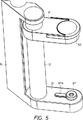
図5は、パウダカートリッジのためのホルダの斜視図である。
図6は、ホルダの下支持部材の分解斜視図である。
図7は、ホルダの下支持部材の断面図である。
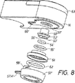
図8は、ホルダの上支持部材の分解斜視図である。
図9は、ホルダの上支持部材の断面図である。
図10は、パウダカートリッジを取り付けていないホルダの側面図である。
図11は、パウダカートリッジを取り付けたホルダの側面図である。
図12は、開放位置にある弁と共に示すパウダカートリッジの下方部分の図4と同様の断面図である。
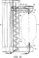
図13は、液体の流と共に示す図11と同様の側面図である。
図14は、水の流れと共に示すホルダおよび上支持部材の平面図である。
図15は、上支持部材が下位置にある状態のホルダの側面図である。
図16は、洗浄、消毒サイクルを実施するために支持部材を連結した状態で示すホルダの側面図である。
図17は、図16に示す位置にある支持部材の断面図である。
図18は、洗浄サイクルの間の水の流を示す図16と同様の図である。
図1を参照すると、本実施形態ではパウダ濃厚物(重炭酸ナトリウム)からの透析液と共に作動するように設定された透析機械10が図示されている。透析機械は、ドゥレークシステム1000(商標)タイプの機械とすることができる。パウダ濃厚物は、1または複数回の処方のための所定量を以て使い捨て可能なカートリッジ11に充填されている。このカートリッジは、固定された下支持部材12と、中空ガイド13において下支持部材12に接近、離反可能に設けられた上支持部材14の間において前記機械に取り付けられている。前記ガイドは、前記機械の外側に設けられた鉛直取付レール16に取り付けられたホルダ15により支持されている。図1には詳細に図示されていないが、それ自体透析機械に関連して周知のように、前記カートリッジに水を通して前記パウダを水に溶かし込むための手段が設けられている。
カートリッジ11(図2、3)は、半球形のドーム形端部を有した円筒形状を呈しており、射出成形されたプラスチック製、好ましくは、ポリプロピレン製の2つの部分11A、11Bから成り、この2つの部分は、外方に突き出した周フランジ17A、17Bにおいて溶接(mirror welding)により相互連結されている。一方の部分11A、つまり上部は、他の部分11B、つまり下部よりも大きな軸方向寸法を有しており、フランジ17A、17Bにおける2つの部分の接合はカートリッジの中心とはなっていない。上部のドーム形の端部には中空スタッドが形成されている。該中空スタッドは、上部11Aに連結された部分18と、部分18から突き出した部分19を有しており、部分18は部分19よりも大きな直径を有している。前記中空スタッドは、カートリッジ内部に連通し、かつ、外側の端部が該スタッドの端壁として形成された薄膜20により閉じられている。
カートリッジの他方の部分11Bのドーム形の端部には、外ネジ22を有する頸部21が形成されている。前記頸部は、軸方向に延びる円形カラー23を有している。該カラーは、平滑な内周面24と、周方向に配列された鋸歯状の外周面25とを有している。キャップ26が、前記頸部に螺着される寸法にて形成され、溝が形成された或いはローレット処理された外周面と、内ネジ27と、端壁28とを有する。キャップの周部に複数のシヤーウェブ29が配設され、かつ、端壁とキャップにおけるその余の部分の間にスリットまたは切欠30が配設されており、該シヤーウェブとスリットにより、前記端壁が前記キャップにおけるその余の部分に連結される。前記スリットまたは切欠は前記シヤーウェブ29により架橋される。端壁28とシヤーウェブ29を有する前記キャップはプラスチック、好ましくは、カートリッジを形成するプラスチック、つまり、ポリプロピレンから射出成形により一体成形される。端壁28は中空スタッド31を有している。該中空スタッドは、前記端壁から突き出しており、かつ、該スタッドの端壁を形成する薄膜32により外側の端部が閉じられている。
端壁28は、周方向に配列された鋸歯状の内周面33を有している。この鋸歯状の内周面は、前記頸部の鋸歯状の外周面25に対して反対方向に向けられている。更に、端壁28には、外周面35を有する環状膨出部34が形成されている。膨出部34には弁要素36が取り付けられている。弁要素は、軸方向に延びるカラー38を有する円形リング37を具備している。このカラーは、その内周面で外周面35に嵌合する寸法を有しており、かつ、内周面に環状ビード39が形成されている。該弁要素を正しく膨出部34に取り付けると、前記ビードが外周面35に形成された環状溝にスナップ式に嵌まり込む。前記弁要素は、また、弁部材40を具備している。弁部材40は、概ね円筒状の形状をしており、かつ、円錐部41により連結された大径部42、小径部43、および、弁部材の下端部に設けられた端壁44とを有して成り、小径部43の外径は、前記中空スタッド31内に突出できるように、該中空スタッドの内径よりも小さくなっている。弁部材は上端部において、4つの細い弾性腕45により、リング37に対して軸方向に移動可能にリング37に連結されている。弁要素を膨出部34に取り付けると、弁部材40の小径部43がスタッド31内に突き出し、腕45のバネ作用により所定の圧力を以て円錐部41が、端壁28においてスタッド31が接合されている部分の内面に当接し、前記弁部材が端壁28に対して密封、係合状態で保持される。また、弁要素36は、好ましくは、ポリプロピレンから射出成形される。
織物から成る、または、射出成形された、好ましくはポリプロピレン製のフィルタネット46が、リング37の上面に形成された凹所に配設され、かつ、超音波溶接により前記リングに連結されている。
このように形成されたカートリッジは、フランジ17A、17Bにおける溶接の気密性を管理するために圧力試験を行った後に、1回の透析処理または複数回の透析処理のための量のパウダ(重炭酸ナトリウム)が前記頸部21から充填され、次いで、端壁28が前記頸部の端面に係合するまで、前記頸部にキャップ26が螺着される。カラー23の平滑な内周面24がカラー38の外周面に嵌合する。カラー38の外周面には前記頸部のカラー23と前記弁要素のカラー38の間をシールするための環状ビード47が形成されている。カラー38は、カラー23の内周面24と膨出部34の外周面35の間にクランプされ、弁要素36と頸部21の間および弁要素36と膨出部34の間に必要なシールを維持する。頸部21は半径方向のフランジ48を有している。該フランジは、前記キャップを螺着したときに、その内縁部49においてフィルタネット46の周縁部の上面に対して密封、係合し、弁要素36を前記キャップに対して位置決めする作用をなす。キャップが完全に螺着される直前に、前記キャップの内周面33と前記頸部の外周面35は相互に係合するが、これらの内外周面に形成されたは歯は小さいので、前記キャップの内周面33は前記頸部の外周面35に対して係合することなく摺動する。次いで、カートリッジは、透析機械に連結されるまで、貯蔵および輸送のために完全に閉じられる。前記ネット、弁要素、および、キャップを含むカートリッジの全ての部品は、一種類の同じプラスチックにより形成されるべきであり、その好ましい材料の1つは既述したようにポリプロピレンである。
次に、図1に示す支持部材12、14を含み既述したカートリッジが取り付けられるホルダを、図5から図11および図13から図18を参照して説明する。固定式の下支持部材12に形成された孔51にブッシュ50が挿入される。該ブッシュの外周フランジ52により形成される肩部が前記支持部材の上面に当接する。大径部53にOリング54から成るガスケットが配設され、フランジにはOリング55から成る他のガスケットが配設される。ブッシュ50内には管56が配設されている。該管は、前記ブッシュに取付可能に形成され、或いは、前記ブッシュと一体成形することができる。前記管の上端は、套管に類似させて斜めに切り欠くことによりテーパ状に形成されており、かつ、下端は、他の管に連結するように形成されている。中心開口部58を有する蓋57がブッシュ52の上方に設けられ、下支持部材12に形成されたスロット59Aに係合する差込みカップリング手段59により支持部材12に取り付けられる。蓋57は腕57Aを有している。該腕の下面には突起57Bが形成されている。蓋を配置して回転させることにより差込みカップリングが係合し、蓋が正しい位置にくると、突起57Bが下支持部材の窪み60にスナップ式に受承される。蓋57は、Oリング54、55を下支持部材に対して正しい位置に保持する。
上支持部材も同様の構成を有しており、既述した構成要素と同様の構成要素は、ダッシュを付して同じ参照番号にて指示されている。然しながら上支持部材の場合、リング61と、Oリング62から成るシールとが配設されている。蓋57′は、下支持部材の蓋57よりも大きな直径を有し、かつ、リング61を上支持部材に対して押圧、保持する。リング61が、次いで、開口部51′内にブッシュ50′を保持すると共に、Oリング54′、55′を正しい位置に保持する。リング61と蓋57′の間に配設されるOリング62は、リング61に受承され、かつ、このリングと前記蓋により正しい位置に保持される。
上支持部材14に設けられた作動部材63は、水平軸64を中心として、図5から図8に示す位置から上方へ図10に示す位置に回動可能に設けられている。前記作動部材には、上支持部材14の内側において、レバー65が連結されている作動部材63が図5から図8に示す位置にあるとき、レバー65の先端は、ガイド13に設けられた切欠66に係合する(図11参照)。こうして、上支持部材14は図11に示す位置に保持される。上支持部材に設けられ、かつ、腕65の凹所65Bに係合する突起65Aにより、作動部材はこの位置に保持される。作動部材63が、上方に回動すると、上支持部材14は、切欠66に係合するレバー65によりガイド13に沿って上方に2cm程移動する。ガイド13の切欠66は、持ち上げられる上支持部材のための当接部を形成する。作動部材63が、更に上方へ図10に示す位置に回動すると、レバー65が切欠66から解除され、上支持部材14はガイド13に沿って自由に下方へ移動可能となる。図10に示す位置において、作動部材は凹所65Bに係合する上支持部材14の他の突起65Cにより保持される。上支持部材14が下方へ下支持部材12の方へ移動し(図15)、レバー65がガイド13の切欠67と係合するとき下位置(図16)となる。
らせん状の管68(図13、14)が中空のガイド13内に配設されている。前記らせん状の管は、端部において下支持部材12と上支持部材14に取り付けられており、透析機械10内に設けられた水管路(図示せず)に連通し、上端において上支持部材14内の管56′に水を供給するために管56′に接続されている。他の管(図示せず)が下支持部材12内の管56に接続されており、これにより透析機械は、透析機械で使用するために濃厚な重炭酸ナトリウム溶液が供給される。
パウダが充填されキャップ26により閉じられた既述のカートリッジ11が、図13において一点鎖線で示すように、下支持部材12と上支持部材14の間に以下に説明するように取り付けられる。
作動部材63を上方へ回動させて(図10)上支持部材14が上方へ2cm程度持ち上げられる。上支持部材14がこの位置において、カートリッジ11のキャップ26のスタッド31を下支持部材12の蓋57の中心開口部からブッシュ50へ挿通させる。スタッド31の周囲をOリング54がシールする。管56の先端が端壁32に対して移動し、カートリッジに十分な圧力が付与され、端壁が貫通される。図4において一点鎖線で示すように管56が端壁に対して押圧されたときに、回動式の蓋として上方に折れ曲がるように、端壁には円形の剪断線(shear line)が形成されている。管56は、ネジキャップ26が下支持部材12の蓋57に係合したときに、前記管が弁部材40に係合して腕45のバネ付勢力に対抗して端壁28の弁座から弁部材を持ち上げる長さを有している。カートリッジの下端をこのように下支持部材12に適用した後、作動部材63は、図11に示す位置へ下方に移動させられ、上支持部材14は、カートリッジ11の上端の中空スタッドの内径よりも小さな直径を有する部分19を上支持部材14のブッシュ50′内に受承し、Oリング54′が該スタッドの周囲をシールする。挿入に際して套管状の管56′の先端が中空スタッドの端壁20を貫通する。カートリッジの上端の中空スタッドの大きいほうの直径を有する部分18が、上支持部材14の蓋57′の中心開口部よりも非常に小さな直径を有しているので、この位置でリング62によるシールは機能しない。この時点で、透析処理用にカートリッジに水を供給してカートリッジ内に充填されたパウダを水に溶かすために、カートリッジは上支持部材14の管56′と下支持部材12の管56の間に取り付けられる。カートリッジからの溶液は濃厚されており、透析機械内で透析処理のために要求される濃度まで希釈される。図13に液体の流れを図示する。図13において、カートリッジ11は一点鎖線でのみ図示されている。然しながら図12の矢印は、カートリッジから頸部21、フィルタネット46、カラー23、38により形成される通路を通過し、腕45を通過し、上動した弁部材40と端壁28により形成される弁座の間を中空スタッド31へ流通し、そしてそこから管56へ流出する液体を示している。液体通路の外側にスリットまたは切欠30が配設されている。
1回または複数回の処理が完了すると、作動部材53を上方に回動させることにより(図10)、上支持部材14が2cm程度持ち上げられ、使用済みカートリッジが取り外される。上支持部材の管56′がカートリッジの上端の中空スタッド19から引き抜かれ、カートリッジが下支持部材から持ち上げられ、ネジキャップ26が管56から引き抜かれ、腕45により弁部材40が再び端壁28の弁座に押圧される。これは、既述のカートリッジの重要な作用である。と言うのは、カートリッジを透析機械から取り外すときに、従来のカートリッジのように、カートリッジ内に残留する液体がカートリッジの下端から流出することがないからである。流出する液体が下支持部材および下支持部材の下側にある透析機械の部品を汚し、そしてこのことが透析機械を取り扱う者にとって非常に好ましくないことであることは言うまでもない。この時点で、カートリッジは流し等に運ぶことが可能となり、そこでカートリッジの下端のネジキャップが取り外され、カートリッジを空にすることができる。頸部21の歯の付いた外周面25と、ネジキャップ26の端壁28の歯の付いた内周面33の間の係合により、ネジキャップを緩めることはそれ自体防止されており、種壁28とネジキャップにおけるその余の部分との間のシヤーウェブ29を切断して、弁要素36と共に端壁28をネジキャップにおけるその余の部分から取り外さなければ、ネジキャップを緩めることができない。端壁を緩めてカートリッジ内部からキャップを通して液体を排出するための通路を開くために、キャップを少し回転させればよい。従って、キャップを完全に緩めて取り外す必要はない。端壁28は、端壁の膨出部34と弁のカラー38の間を十分にシールするために、両者間のとまりばめが必要であるとの事実のために、端壁28が緊密に前記頸部に張り付いている限り、キャップを緩めた後に、指により頸部から端壁を引き離す必要があるかもしれない。端壁が緩み落下すると、或いは、指で引き離すと、キャップは直ちにカートリッジを閉じるために使用することができなくなり、従って、間違った量、パウダを充填したり、カートリッジ内部が汚染される危険を伴って、使用現場でカートリッジにパウダを再充填することができなくなる。
カートリッジは使用後廃棄されなければならないが、好ましい実施形態で説明したようにネジキャップと弁要素が1つの材料、例えばポリプロピレンで形成されている場合には、端壁を含むネジキャップと弁要素が同じであるので、その材料は再生可能であり、特定の都合の良い方法にて再生のために集めることができる。
透析処理の後に、透析機械の洗浄、消毒サイクルが実施され、消毒液を一方の支持部材から他方の支持部材へ、両者間に取り付けたカートリッジを通して流通させる。洗浄、消毒サイクルを実施するために、既述したように、上支持部材14を下位置に移動させて下支持部材12に係合させる。作動部材63を上方へ回動させ(図10)、腕65をガイド13の上切欠66から解除し、管68を圧縮しながら上支持部材をガイドに沿って下方に図15の位置へ押し下げ、かつ、作動部材63を下方へ回動させ下切欠67に係合させ、上支持部材14を下支持部材12に係合させる(図16、18)。下支持部材12の蓋57が、上支持部材14の蓋57′を受承する(図17)。下支持部材12の蓋57は、図17に示すように、上支持部材14のOリング62が蓋57の外面に対してシールできる寸法にて形成されている。然しながら、支持部材の該位置においてOリング54、54′は、シール作用を果たさない。このとき、洗浄、消毒液を管68を通して上支持部材14に供給可能となる。流れの回路は、図18に示すように下支持部材12への短絡回路となる。図17から理解されるように、Oリング54、54′は、洗浄、消毒サイクルにおいて流通する液体に曝されている。このことは重要である。と言うのは、これらのOリングは、カートリッジの2つの端部における連結部をシールしなければならないが、Oリングに重炭酸塩の堆積やコーティングがあると、このシールが害されるからである。然しながら、Oリング62は洗浄する必要はない。と言うのは、このOリングは透析に際してシール作用を果たさないからである。
必要に応じて差込みカップリングにより蓋57、57′を関連する支持部材から容易に取り外して、Oリングに接近、交換することができるので、前記Oリングは容易に交換可能である。また、管56、56′を有するブッシュ50、50′は、何回か使用した後に前記管の先端が鈍くなったときに、必要に応じて同じ理由から容易に交換することができる。このカートリッジのホルダは、メンテナンスおよび修理に適している。
既述した実施形態は本発明の請求の範囲内で修正することができ、前記ネジキャップは他の形態にて構成することができる。
図示する実施形態では、シールリングは差込みカップリングにより支持部材に着脱自在に取り付けられた蓋により正しい位置に保持されているが、支持部材に中空スタッドを設けて、この中空スタッドに螺着するようにできる蓋を取り付けるために他のタイプの迅速カップリングを用いても良い。
移動可能な支持部材をガイド上にて異なる複数の位置に係止するための装置は図示する構成とは異なる構成とすることができる。移動可能な支持部材をガイド上において異なる位置にクランプしてもよいし、ネジ/ナット装置やラック/ギア装置により移動させても良い。リンク装置を用いて2つの支持部材を互いに平行に接近、離反させてもよい。
突起65A、65Cの各々はバネにより付勢され座に取り付けられたボールに置換することができる。このボールは、腕65によりバネの付勢力に対抗して凹所65bにスナップ式に押圧される。
Oリングは適切なシールリングであるが、既述した装置に他の形式のシールリングを用いることができることは言うまでもない。
本発明の装置は、支持部材との連結をシールするために中空のスタッドを有するが図示する実施形態とは異なる適応例でカートリッジを取り付けるために用いることができる。The present invention relates to an apparatus for replaceably connecting a powder cartridge between an inlet and an outlet for liquid in a dialysis machine.
In the dialysis system disclosed in European Patent Publication No. B1 0278100, dialysate is prepared from a closed container, ie, powder (sodium bicarbonate) in a cartridge at the point of use. The cartridge is mounted on a dialysis machine holder and connected to an inlet for supplying water and an outlet for a concentrated solution of the powder. The concentrated liquid is obtained by dissolving the powder through water into the cartridge. In the dialysis machine, precisely metered water is added to this concentrated solution to obtain a dialysate having a predetermined concentration.
In a commercially available dialysis machine, Gambro AK 100, operating with this system, the cartridge is mounted between two support members (yaw) that are pivotally attached to the vertical wall of the dialysis machine. One of the support members has an inlet for water, and the other has an outlet for concentrated liquid obtained by circulating water through the cartridge and dissolving powder in the water. The inlet and outlet are connected to hollow studs provided at both ends of the cartridge. A thin film is provided to close the hollow stud, and the cartridge is connected through the thin film. When placing the cartridge between the two support members, or when removing the cartridge from this position, the upper support member is pivoted upwards, however, the two support members are also used in the dialysis machine. It can be rotated toward the wall surface. That is, the upper support member is rotated downward, the lower support member is rotated upward, and the inlet / outlet is connected between the connection elements having the same dimensions as the hollow stud of the cartridge provided on the wall surface. Is provided with a short circuit, and the liquid can be circulated in the short circuit from one support member to the other support member without a cartridge. This short circuit is used when cleaning and disinfection are performed by circulating and circulating a disinfectant solution through a dialysis machine when one dialysis treatment is completed between two dialysis treatments and another dialysis treatment is performed.
After dialysis, some liquid remains in the cartridge. When the cartridge is removed from the prior art dialysis machine after the dialysis process is finished, the liquid will wet the seal ring to seal the periphery of the cartridge's hollow stud as well as the lower support member and it will solidify there Can not be prevented. As the water evaporates, solid powder remains on the seal ring. This is not removed in the wash cycle. This is because the seal ring seals around the connection element of the short circuit of the dialysis machine. The powder solidified or deposited on the seal ring damages the seal ring, lowers its sealing action, and requires replacement. In prior art dialysis machines, changing the ring requires a cumbersome and time-consuming installation operation.
It is an object of the present invention to clean and sterilize a seal ring that seals between a hollow stud and an inlet / outlet of a cartridge, exposes it during a sterilization cycle, and easily removes a reel without performing extensive removal and installation work. By providing an apparatus of the type already described that allows the ring to be attached to the support member, the above-mentioned drawbacks are eliminated.
The object of the invention described above is achieved by a cartridge according to the invention as described in the characterizing part of claim 1.
In order to describe the present invention in more detail, embodiments will be described with reference to the accompanying drawings. In the accompanying drawings,
FIG. 1 is a perspective view of a dialysis machine equipped with a device according to the present invention.
FIG. 2 is a perspective view of a powder cartridge attached to a dialysis machine.
FIG. 3 is an exploded perspective view of the powder cartridge.
FIG. 4 is a cross-sectional view of the lower portion of the powder cartridge having a neck and a screw cap and the valve in the closed position provided on the screw cap.
FIG. 5 is a perspective view of a holder for the powder cartridge.
FIG. 6 is an exploded perspective view of the lower support member of the holder.
FIG. 7 is a cross-sectional view of the lower support member of the holder.
FIG. 8 is an exploded perspective view of the upper support member of the holder.
FIG. 9 is a cross-sectional view of the upper support member of the holder.
FIG. 10 is a side view of a holder to which no powder cartridge is attached.
FIG. 11 is a side view of the holder to which the powder cartridge is attached.
12 is a cross-sectional view similar to FIG. 4 of the lower portion of the powder cartridge shown with the valve in the open position.
FIG. 13 is a side view similar to FIG.
FIG. 14 is a plan view of the holder and the upper support member shown together with the flow of water.
FIG. 15 is a side view of the holder with the upper support member in the lower position.
FIG. 16 is a side view of the holder shown in a state where the support members are connected to perform the cleaning and disinfection cycle.
17 is a cross-sectional view of the support member in the position shown in FIG.
FIG. 18 is a view similar to FIG. 16 showing the flow of water during the wash cycle.
Referring to FIG. 1, a dialysis machine 10 is shown in this embodiment that is set up to operate with dialysate from a powder concentrate (sodium bicarbonate). The dialysis machine may be a Drake System 1000 ™ type machine. The powder concentrate is filled in a
The cartridge 11 (FIGS. 2 and 3) has a cylindrical shape with a hemispherical dome-shaped end and consists of two
A
The
A
The cartridge formed in this manner is subjected to a pressure test to manage the gas tightness of the welds at the
Next, a holder to which the above-described cartridge including the
The upper support member has the same configuration, and components similar to those described above are indicated by the same reference numerals with dashes. However, in the case of the upper support member, a
The
A helical tube 68 (FIGS. 13 and 14) is disposed in the
The above-described
The
When one or more processes are completed, the
The cartridge must be discarded after use, but if the screw cap and valve element are formed of one material, for example polypropylene, as described in the preferred embodiment, the screw cap and valve element including the end wall Since they are the same, the material is recyclable and can be collected for regeneration in a particular convenient way.
After the dialysis treatment, a dialysis machine cleaning and disinfecting cycle is performed, and the disinfecting liquid is circulated from one support member to the other support member through a cartridge attached therebetween. In order to perform the cleaning and disinfection cycle, the
If necessary, the O-rings can be easily replaced because the
The above-described embodiments can be modified within the scope of the claims of the present invention, and the screw cap can be configured in other forms.
In the illustrated embodiment, the seal ring is held in the correct position by a lid that is detachably attached to the support member by an insertion coupling. However, the support member is provided with a hollow stud and is screwed to the hollow stud. Other types of quick couplings may be used to attach the lid that can be made.
The device for locking the movable support member at a plurality of different positions on the guide may have a different configuration from that shown. The movable support member may be clamped at a different position on the guide, or may be moved by a screw / nut device or a rack / gear device. Two support members may be approached and separated in parallel with each other using a link device.
Each of the
O-rings are suitable seal rings, but it will be appreciated that other types of seal rings can be used in the previously described apparatus.
The apparatus of the present invention has a hollow stud to seal the connection with the support member, but can be used to mount the cartridge in a different application than the illustrated embodiment.
Claims (15)
該装置は:
第1の支持部材および第2の支持部材であって、該第1の支持部材が該入口を備え、そして該第2の支持部材が該出口を備える、支持部材、
該第1の支持部材および該第2の支持部材の少なくとも1つを、他の支持部材に対して、直線状に接近および離反可能に案内する手段であって、該案内する手段が、該支持部材を該パウダカートリッジと係合し、そして該入口と該出口とを流体連結し、そして該支持部材を脱係合し、
ここで、該支持部材と該パウダカートリッジとの係合に際し、該支持部材の各々が、該カートリッジを通じて液体を導くため、かつ該入口および該出口を直接相互接続するように該第1の支持部材および該第2の支持部材を互いに係合するために、該支持部材の間に位置する該パウダカートリッジ上の該中空スタッドの1つに係合する、手段、および
該パウダカートリッジの対向する端部上の中空スタッドの1つに対し該支持部材の各々をシールするための各支持部材上のシール手段を備える、透析機械。 End liquids inlet port and a liquid outlet, and, a dialysis machine having the form of a device to exchange coupling the powder cartridge between an inlet and outlet, the powder cartridge, you its opposite Each part includes a hollow stud ,
The device:
A first support member and second support member, with the first support member inlet and the second support member comprises a outlet, the support member,
Means for guiding at least one of the first support member and the second support member relative to the other support members so as to be linearly approachable and disengageable, the guiding means being the support the member engages the said powder cartridge and the inlet and outlet fluid connection, and disengages the support member,
In here, when the engagement between the support member and the powder cartridge, each of said support members, because the directing liquid through the cartridge, and the inlet and the first to directly interconnect the outlet for engaging the support member and the second support member to each other, engage in one of the hollow studs on the powder cartridge located between the support member, means, and a counter of the powder cartridge one of the hollow studs on the ends that respect provided with sealing means on the support members for sealing each of the support members, the dialysis machine.
Applications Claiming Priority (3)
| Application Number | Priority Date | Filing Date | Title |
|---|---|---|---|
| SE9502397-4 | 1995-07-03 | ||
| SE9502397A SE504633C2 (en) | 1995-07-03 | 1995-07-03 | Device for dialysis machine |
| PCT/SE1996/000897 WO1997002056A1 (en) | 1995-07-03 | 1996-07-03 | A device in a dialysis machine |
Related Child Applications (1)
| Application Number | Title | Priority Date | Filing Date |
|---|---|---|---|
| JP2006031614A Division JP2006122719A (en) | 1995-07-03 | 2006-02-08 | Device in dialysis machine |
Publications (2)
| Publication Number | Publication Date |
|---|---|
| JPH11508469A JPH11508469A (en) | 1999-07-27 |
| JP3848371B2 true JP3848371B2 (en) | 2006-11-22 |
Family
ID=20398819
Family Applications (2)
| Application Number | Title | Priority Date | Filing Date |
|---|---|---|---|
| JP50508297A Expired - Fee Related JP3848371B2 (en) | 1995-07-03 | 1996-07-03 | Dialysis machine equipment |
| JP2006031614A Withdrawn JP2006122719A (en) | 1995-07-03 | 2006-02-08 | Device in dialysis machine |
Family Applications After (1)
| Application Number | Title | Priority Date | Filing Date |
|---|---|---|---|
| JP2006031614A Withdrawn JP2006122719A (en) | 1995-07-03 | 2006-02-08 | Device in dialysis machine |
Country Status (12)
| Country | Link |
|---|---|
| US (1) | US6036858A (en) |
| EP (1) | EP0841959B1 (en) |
| JP (2) | JP3848371B2 (en) |
| AT (1) | ATE225194T1 (en) |
| AU (1) | AU6325996A (en) |
| DE (1) | DE69624118T2 (en) |
| DK (1) | DK0841959T3 (en) |
| ES (1) | ES2183963T3 (en) |
| PT (1) | PT841959E (en) |
| RU (1) | RU2159634C2 (en) |
| SE (1) | SE504633C2 (en) |
| WO (1) | WO1997002056A1 (en) |
Families Citing this family (69)
| Publication number | Priority date | Publication date | Assignee | Title |
|---|---|---|---|---|
| GR970100152A (en) * | 1997-04-18 | 1998-12-31 | Doctum ������������ �. �������� ��� ��� �� | Innovative device-dispenser, containing sodium bicarbonate, incorporating filters on both ends, used in hemodialysis with bicarbonates. |
| SE520638C2 (en) * | 1998-01-21 | 2003-08-05 | Gambro Lundia Ab | Safety device for dialysis machine |
| DE19852982C1 (en) * | 1998-11-17 | 2000-03-16 | Braun Melsungen Ag | Cartridge holder for dialysis machine has lower cheek with outlet connection and upper cheek with inflow connection, with cartridge being insertable between cheeks |
| IT1307734B1 (en) * | 1999-01-29 | 2001-11-19 | Bieffe Medital Spa | CARTRIDGE FOR DIALYSIS CONTAINING SODIUM BICARBONATE. |
| US6355161B1 (en) | 1999-10-12 | 2002-03-12 | Aksys, Ltd. | Bottles for dialysis machines and method for automatically identifying such bottles |
| DE10152105A1 (en) * | 2001-10-23 | 2003-05-08 | Fresenius Medical Care De Gmbh | Container for use in dialysis |
| US7247146B2 (en) | 2003-02-07 | 2007-07-24 | Gambro Lundia Ab | Support element for an integrated blood treatment module, integrated blood treatment module and extracorporeal blood treatment apparatus equipped with said integrated module |
| US7314554B2 (en) | 2003-02-07 | 2008-01-01 | Gambro Lundia Ab | Extracorporeal blood treatment machine |
| US7223338B2 (en) | 2003-02-07 | 2007-05-29 | Gambro Lundia Ab | Support element for an integrated module for blood treatment, an integrated module for blood treatment, and a manufacturing process for an integrated module for blood treatment |
| US7223336B2 (en) | 2003-02-07 | 2007-05-29 | Gambro Lundia Ab | Integrated blood treatment module and extracorporeal blood treatment apparatus |
| US7591945B2 (en) | 2003-02-07 | 2009-09-22 | Gambro Lundia Ab | Support device for containers in extracorporeal blood treatment machines |
| US7850659B1 (en) * | 2003-08-18 | 2010-12-14 | Medrad, Inc. | Fluid container holding device, fluid delivery system and method of use therefor |
| US8029454B2 (en) * | 2003-11-05 | 2011-10-04 | Baxter International Inc. | High convection home hemodialysis/hemofiltration and sorbent system |
| US8038639B2 (en) | 2004-11-04 | 2011-10-18 | Baxter International Inc. | Medical fluid system with flexible sheeting disposable unit |
| JP4655296B2 (en) * | 2005-05-23 | 2011-03-23 | 日機装株式会社 | Container holder |
| US7871391B2 (en) | 2005-10-21 | 2011-01-18 | Fresenius Medical Care Holdings, Inc. | Extracorporeal fluid circuit |
| US8631683B2 (en) | 2007-02-06 | 2014-01-21 | Fresenius Medical Care Holdings, Inc. | Dialysis systems including non-invasive multi-function sensor systems |
| DE102007009269B4 (en) * | 2007-02-26 | 2010-11-11 | Fresenius Medical Care Deutschland Gmbh | Device and method for filling and / or emptying a dialysis machine |
| EP3150238B1 (en) | 2007-09-19 | 2018-03-14 | Fresenius Medical Care Holdings, Inc. | Dialysis systems and related components |
| US7938967B2 (en) | 2007-09-19 | 2011-05-10 | Fresenius Medical Care Holdings, Inc. | Safety vent structure for extracorporeal circuit |
| WO2009044221A1 (en) | 2007-10-04 | 2009-04-09 | Gambro Lundia Ab | An infusion apparatus |
| US8114276B2 (en) | 2007-10-24 | 2012-02-14 | Baxter International Inc. | Personal hemodialysis system |
| NZ600274A (en) * | 2007-11-16 | 2013-03-28 | Fresenius Med Care Hldg Inc | Dialysis systems and methods |
| US8889004B2 (en) | 2007-11-16 | 2014-11-18 | Fresenius Medical Care Holdings, Inc. | Dialysis systems and methods |
| WO2011017215A1 (en) | 2009-08-04 | 2011-02-10 | Fresenius Medical Care Holdings, Inc. | Dialysis systems, components, and methods |
| US9220832B2 (en) | 2010-01-07 | 2015-12-29 | Fresenius Medical Care Holdings, Inc. | Dialysis systems and methods |
| US8500994B2 (en) | 2010-01-07 | 2013-08-06 | Fresenius Medical Care Holdings, Inc. | Dialysis systems and methods |
| US8449686B2 (en) | 2010-04-26 | 2013-05-28 | Fresenius Medical Care Holdings, Inc. | Methods for cleaning a drain line of a dialysis machine |
| WO2012041790A1 (en) * | 2010-09-28 | 2012-04-05 | Akzo Nobel Chemicals International B.V. | Process and container for dissolving salt |
| US8784668B2 (en) | 2010-10-12 | 2014-07-22 | Fresenius Medical Care Holdings, Inc. | Systems and methods for compensation of compliant behavior in regenerative dialysis systems |
| CN102125707B (en) * | 2011-01-27 | 2012-07-25 | 重庆山外山科技有限公司 | Dry powder cylinder device for blood purification |
| DE102011009908A1 (en) | 2011-01-31 | 2012-08-02 | Fresenius Medical Care Deutschland Gmbh | Clamping holder for a syringe of a dosing device, dosing device and blood treatment device |
| US9333286B2 (en) | 2011-05-12 | 2016-05-10 | Fresenius Medical Care Holdings, Inc. | Medical tubing installation detection |
| US8836519B2 (en) | 2011-05-12 | 2014-09-16 | Fresenius Medical Care Holdings, Inc. | Determining the absence or presence of fluid in a dialysis system |
| WO2013028809A2 (en) * | 2011-08-22 | 2013-02-28 | Medtronic, Inc. | Dual flow sorbent cartridge |
| US8906240B2 (en) | 2011-08-29 | 2014-12-09 | Fresenius Medical Care Holdings, Inc. | Early detection of low bicarbonate level |
| US8992777B2 (en) | 2011-11-18 | 2015-03-31 | Fresenius Medical Care Holdings, Inc. | Systems and methods for providing notifications in dialysis systems |
| AU343633S (en) * | 2012-01-12 | 2012-08-01 | Draegerwerk Ag & Co Kgaa | Anaesthetic apparatus |
| US9165112B2 (en) | 2012-02-03 | 2015-10-20 | Fresenius Medical Care Holdings, Inc. | Systems and methods for displaying objects at a medical treatment apparatus display screen |
| DE102012002497A1 (en) * | 2012-02-10 | 2013-08-14 | Fresenius Medical Care Deutschland Gmbh | Connector with a container for the production of a customized solution for dialysis |
| DE102012111428A1 (en) * | 2012-11-26 | 2014-05-28 | B. Braun Avitum Ag | Cartridge holder for a dialysis machine |
| DE102012111429A1 (en) * | 2012-11-26 | 2014-06-18 | B. Braun Avitum Ag | Cartridge holder of a dialysis machine with integrated positioning aid |
| US9713666B2 (en) | 2013-01-09 | 2017-07-25 | Medtronic, Inc. | Recirculating dialysate fluid circuit for blood measurement |
| US9144640B2 (en) | 2013-02-02 | 2015-09-29 | Medtronic, Inc. | Sorbent cartridge configurations for improved dialysate regeneration |
| US9433721B2 (en) | 2013-06-25 | 2016-09-06 | Fresenius Medical Care Holdings, Inc. | Vial spiking assemblies and related methods |
| US9884145B2 (en) | 2013-11-26 | 2018-02-06 | Medtronic, Inc. | Parallel modules for in-line recharging of sorbents using alternate duty cycles |
| US9895477B2 (en) | 2013-11-26 | 2018-02-20 | Medtronic, Inc. | Detachable module for recharging sorbent materials with optional bypass |
| US10052612B2 (en) | 2013-11-26 | 2018-08-21 | Medtronic, Inc. | Zirconium phosphate recharging method and apparatus |
| US10004839B2 (en) | 2013-11-26 | 2018-06-26 | Medtronic, Inc. | Multi-use sorbent cartridge |
| US9943780B2 (en) | 2013-11-26 | 2018-04-17 | Medtronic, Inc. | Module for in-line recharging of sorbent materials with optional bypass |
| US10537875B2 (en) | 2013-11-26 | 2020-01-21 | Medtronic, Inc. | Precision recharging of sorbent materials using patient and session data |
| WO2015199761A1 (en) | 2014-06-24 | 2015-12-30 | Medtronic, Inc. | Sorbent pouch |
| WO2015199766A1 (en) | 2014-06-24 | 2015-12-30 | Medtronic, Inc. | Modular dialysate regeneration assembly |
| US10272363B2 (en) | 2014-06-24 | 2019-04-30 | Medtronic, Inc. | Urease introduction system for replenishing urease in a sorbent cartridge |
| EP3160529B1 (en) | 2014-06-24 | 2019-11-13 | Medtronic Inc. | Replenishing urease in dialysis systems using urease pouches |
| CN106659828B (en) | 2014-06-24 | 2019-05-03 | 美敦力公司 | Use the urase in urase introducer supplement dialysis system |
| WO2015199768A1 (en) | 2014-06-24 | 2015-12-30 | Medtronic, Inc. | Stacked sorbent assembly |
| EP2979712B1 (en) * | 2014-07-31 | 2017-03-22 | Gambro Lundia AB | Medical apparatus for the preparation of medical fluid |
| US9974942B2 (en) | 2015-06-19 | 2018-05-22 | Fresenius Medical Care Holdings, Inc. | Non-vented vial drug delivery |
| JP2018201532A (en) * | 2015-09-29 | 2018-12-27 | 日機装株式会社 | Dialysis liquid supply device |
| US10981148B2 (en) | 2016-11-29 | 2021-04-20 | Medtronic, Inc. | Zirconium oxide module conditioning |
| US11167070B2 (en) | 2017-01-30 | 2021-11-09 | Medtronic, Inc. | Ganged modular recharging system |
| US10960381B2 (en) | 2017-06-15 | 2021-03-30 | Medtronic, Inc. | Zirconium phosphate disinfection recharging and conditioning |
| US11213616B2 (en) | 2018-08-24 | 2022-01-04 | Medtronic, Inc. | Recharge solution for zirconium phosphate |
| CA3133332A1 (en) * | 2019-04-30 | 2020-11-05 | Dean Hu | Dialysis system and methods |
| CN110124141B (en) * | 2019-06-11 | 2021-09-21 | 聊城市人民医院 | Blood perfusion device |
| EP3791903A1 (en) * | 2019-09-12 | 2021-03-17 | Fresenius Medical Care Deutschland GmbH | System and method for connecting a concentrate container with a blood treatment device |
| WO2021048301A1 (en) * | 2019-09-12 | 2021-03-18 | Fresenius Medical Care Deutschland Gmbh | System and method for connecting a concentrate container with a blood treatment device |
| CN112472893A (en) * | 2019-09-12 | 2021-03-12 | 费森尤斯医疗护理德国有限责任公司 | System and method for connecting a concentrate container to a blood processing device |
Family Cites Families (10)
| Publication number | Priority date | Publication date | Assignee | Title |
|---|---|---|---|---|
| US3872868A (en) * | 1973-09-27 | 1975-03-25 | Joel B Kline | Universal hospital container |
| US4005844A (en) * | 1975-08-25 | 1977-02-01 | Stryker Corporation | Solution bottle holder |
| US4387873A (en) * | 1981-03-16 | 1983-06-14 | Baxter Travenol Laboratories, Inc. | Device for suspension of a solution container |
| US4676467A (en) * | 1985-10-31 | 1987-06-30 | Cobe Laboratories, Inc. | Apparatus for supporting a fluid flow cassette |
| US4784495A (en) * | 1987-02-06 | 1988-11-15 | Gambro Ab | System for preparing a fluid intended for a medical procedure by mixing at least one concentrate in powder form with water |
| SE505967C2 (en) * | 1990-10-15 | 1997-10-27 | Gambro Ab | The respective method for preparing a medical solution, for example a dialysis solution |
| DE4138140C2 (en) * | 1991-11-20 | 1993-12-23 | Fresenius Ag | Device for disinfecting hemodialysis machines with a powdered concentrate |
| US5275724A (en) * | 1991-12-10 | 1994-01-04 | Millipore Corporation | Connector apparatus and system |
| SE504572C2 (en) * | 1995-06-06 | 1997-03-10 | Gambro Ab | Combined holder and connector for dialyzer |
| US5641144A (en) * | 1995-06-07 | 1997-06-24 | Cobe Laboratories, Inc. | Dialyzer holder |
-
1995
- 1995-07-03 SE SE9502397A patent/SE504633C2/en not_active IP Right Cessation
-
1996
- 1996-07-03 DE DE69624118T patent/DE69624118T2/en not_active Expired - Lifetime
- 1996-07-03 DK DK96922362T patent/DK0841959T3/en active
- 1996-07-03 EP EP96922362A patent/EP0841959B1/en not_active Expired - Lifetime
- 1996-07-03 RU RU98101630/14A patent/RU2159634C2/en not_active IP Right Cessation
- 1996-07-03 US US08/983,592 patent/US6036858A/en not_active Expired - Lifetime
- 1996-07-03 AU AU63259/96A patent/AU6325996A/en not_active Abandoned
- 1996-07-03 WO PCT/SE1996/000897 patent/WO1997002056A1/en active IP Right Grant
- 1996-07-03 JP JP50508297A patent/JP3848371B2/en not_active Expired - Fee Related
- 1996-07-03 AT AT96922362T patent/ATE225194T1/en not_active IP Right Cessation
- 1996-07-03 PT PT96922362T patent/PT841959E/en unknown
- 1996-07-03 ES ES96922362T patent/ES2183963T3/en not_active Expired - Lifetime
-
2006
- 2006-02-08 JP JP2006031614A patent/JP2006122719A/en not_active Withdrawn
Also Published As
| Publication number | Publication date |
|---|---|
| SE9502397L (en) | 1997-01-04 |
| JPH11508469A (en) | 1999-07-27 |
| DK0841959T3 (en) | 2002-10-28 |
| EP0841959A1 (en) | 1998-05-20 |
| ES2183963T3 (en) | 2003-04-01 |
| SE9502397D0 (en) | 1995-07-03 |
| JP2006122719A (en) | 2006-05-18 |
| WO1997002056A1 (en) | 1997-01-23 |
| DE69624118T2 (en) | 2003-06-05 |
| ATE225194T1 (en) | 2002-10-15 |
| PT841959E (en) | 2002-12-31 |
| RU2159634C2 (en) | 2000-11-27 |
| DE69624118D1 (en) | 2002-11-07 |
| US6036858A (en) | 2000-03-14 |
| SE504633C2 (en) | 1997-03-24 |
| AU6325996A (en) | 1997-02-05 |
| EP0841959B1 (en) | 2002-10-02 |
Similar Documents
| Publication | Publication Date | Title |
|---|---|---|
| JP3848371B2 (en) | Dialysis machine equipment | |
| JP2006181377A (en) | Powder cartridge device for dialysis machine | |
| JP3184644B2 (en) | Hemodialysis machine | |
| JP5220435B2 (en) | Cleaning tube and endoscope cleaning / disinfecting device | |
| US6050278A (en) | Dialyzer precleaning system | |
| JP2002507905A (en) | Apparatus and method for sterilizing medical devices | |
| EP0717316A1 (en) | Apparatus for emptying and rinsing out photographic chemical containers into a mixing tank | |
| JP5830473B2 (en) | Device for disinfection, sterilization and / or maintenance of medical, in particular dental instruments | |
| JPH11137506A (en) | Endoscope washing/disinfecting apparatus | |
| JP3300889B2 (en) | Dialyzer aseptic connection socket | |
| WO2019244745A1 (en) | Filter replacement method, filter device, automatic wet-down system | |
| US20060144776A1 (en) | Manual dialyzer header cleaning device | |
| AU2016286269B2 (en) | Process water supply unit for supplying a medical treatment unit, dental medical treatment unit and operating method | |
| JP2001521776A (en) | Filters used for dental instruments | |
| JP2006158967A (en) | Appliance for supplying liquid working substance for medical or dental-medical work station | |
| CA2223473C (en) | Device in a dialysis machine | |
| WO1998050090A1 (en) | Bacteria removing filter unit for hemodialyzer and hemodialyzer with bacteria removing filter | |
| WO1999002205A1 (en) | Automatic exchanger for peritoneal dialysis | |
| JPH049527B2 (en) | ||
| JP2573622B2 (en) | Endoscope cleaning and disinfecting equipment | |
| EP4028074A1 (en) | System and method for connecting a concentrate container with a blood treatment device without leakages | |
| CN112387446A (en) | Spray sterilizer and use method thereof | |
| JPS63248604A (en) | Germless filling method of fluid into bag | |
| CN114364413A (en) | System and method for connecting a concentrate container to a blood processing device | |
| CN112472893A (en) | System and method for connecting a concentrate container to a blood processing device |
Legal Events
| Date | Code | Title | Description |
|---|---|---|---|
| A131 | Notification of reasons for refusal |
Free format text: JAPANESE INTERMEDIATE CODE: A131 Effective date: 20051206 |
|
| A521 | Request for written amendment filed |
Free format text: JAPANESE INTERMEDIATE CODE: A523 Effective date: 20060208 |
|
| A72 | Notification of change in name of applicant |
Free format text: JAPANESE INTERMEDIATE CODE: A721 Effective date: 20060208 |
|
| TRDD | Decision of grant or rejection written | ||
| A01 | Written decision to grant a patent or to grant a registration (utility model) |
Free format text: JAPANESE INTERMEDIATE CODE: A01 Effective date: 20060808 |
|
| A61 | First payment of annual fees (during grant procedure) |
Free format text: JAPANESE INTERMEDIATE CODE: A61 Effective date: 20060825 |
|
| R150 | Certificate of patent or registration of utility model |
Free format text: JAPANESE INTERMEDIATE CODE: R150 |
|
| FPAY | Renewal fee payment (event date is renewal date of database) |
Free format text: PAYMENT UNTIL: 20100901 Year of fee payment: 4 |
|
| FPAY | Renewal fee payment (event date is renewal date of database) |
Free format text: PAYMENT UNTIL: 20110901 Year of fee payment: 5 |
|
| FPAY | Renewal fee payment (event date is renewal date of database) |
Free format text: PAYMENT UNTIL: 20110901 Year of fee payment: 5 |
|
| FPAY | Renewal fee payment (event date is renewal date of database) |
Free format text: PAYMENT UNTIL: 20120901 Year of fee payment: 6 |
|
| FPAY | Renewal fee payment (event date is renewal date of database) |
Free format text: PAYMENT UNTIL: 20120901 Year of fee payment: 6 |
|
| FPAY | Renewal fee payment (event date is renewal date of database) |
Free format text: PAYMENT UNTIL: 20130901 Year of fee payment: 7 |
|
| LAPS | Cancellation because of no payment of annual fees |