JP3845408B2 - Memory module heat dissipation device - Google Patents
Memory module heat dissipation device Download PDFInfo
- Publication number
- JP3845408B2 JP3845408B2 JP2003347404A JP2003347404A JP3845408B2 JP 3845408 B2 JP3845408 B2 JP 3845408B2 JP 2003347404 A JP2003347404 A JP 2003347404A JP 2003347404 A JP2003347404 A JP 2003347404A JP 3845408 B2 JP3845408 B2 JP 3845408B2
- Authority
- JP
- Japan
- Prior art keywords
- heat sink
- memory module
- memory
- heat
- substrate
- Prior art date
- Legal status (The legal status is an assumption and is not a legal conclusion. Google has not performed a legal analysis and makes no representation as to the accuracy of the status listed.)
- Expired - Fee Related
Links
Images


Classifications
-
- H—ELECTRICITY
- H01—ELECTRIC ELEMENTS
- H01L—SEMICONDUCTOR DEVICES NOT COVERED BY CLASS H10
- H01L23/00—Details of semiconductor or other solid state devices
- H01L23/34—Arrangements for cooling, heating, ventilating or temperature compensation ; Temperature sensing arrangements
- H01L23/40—Mountings or securing means for detachable cooling or heating arrangements ; fixed by friction, plugs or springs
- H01L23/4006—Mountings or securing means for detachable cooling or heating arrangements ; fixed by friction, plugs or springs with bolts or screws
-
- H—ELECTRICITY
- H01—ELECTRIC ELEMENTS
- H01L—SEMICONDUCTOR DEVICES NOT COVERED BY CLASS H10
- H01L23/00—Details of semiconductor or other solid state devices
- H01L23/34—Arrangements for cooling, heating, ventilating or temperature compensation ; Temperature sensing arrangements
- H01L23/36—Selection of materials, or shaping, to facilitate cooling or heating, e.g. heatsinks
- H01L23/367—Cooling facilitated by shape of device
- H01L23/3672—Foil-like cooling fins or heat sinks
-
- H—ELECTRICITY
- H01—ELECTRIC ELEMENTS
- H01L—SEMICONDUCTOR DEVICES NOT COVERED BY CLASS H10
- H01L25/00—Assemblies consisting of a plurality of individual semiconductor or other solid state devices ; Multistep manufacturing processes thereof
- H01L25/03—Assemblies consisting of a plurality of individual semiconductor or other solid state devices ; Multistep manufacturing processes thereof all the devices being of a type provided for in the same subgroup of groups H01L27/00 - H01L33/00, or in a single subclass of H10K, H10N, e.g. assemblies of rectifier diodes
- H01L25/04—Assemblies consisting of a plurality of individual semiconductor or other solid state devices ; Multistep manufacturing processes thereof all the devices being of a type provided for in the same subgroup of groups H01L27/00 - H01L33/00, or in a single subclass of H10K, H10N, e.g. assemblies of rectifier diodes the devices not having separate containers
- H01L25/065—Assemblies consisting of a plurality of individual semiconductor or other solid state devices ; Multistep manufacturing processes thereof all the devices being of a type provided for in the same subgroup of groups H01L27/00 - H01L33/00, or in a single subclass of H10K, H10N, e.g. assemblies of rectifier diodes the devices not having separate containers the devices being of a type provided for in group H01L27/00
- H01L25/0652—Assemblies consisting of a plurality of individual semiconductor or other solid state devices ; Multistep manufacturing processes thereof all the devices being of a type provided for in the same subgroup of groups H01L27/00 - H01L33/00, or in a single subclass of H10K, H10N, e.g. assemblies of rectifier diodes the devices not having separate containers the devices being of a type provided for in group H01L27/00 the devices being arranged next and on each other, i.e. mixed assemblies
-
- H—ELECTRICITY
- H01—ELECTRIC ELEMENTS
- H01L—SEMICONDUCTOR DEVICES NOT COVERED BY CLASS H10
- H01L23/00—Details of semiconductor or other solid state devices
- H01L23/34—Arrangements for cooling, heating, ventilating or temperature compensation ; Temperature sensing arrangements
- H01L23/40—Mountings or securing means for detachable cooling or heating arrangements ; fixed by friction, plugs or springs
- H01L23/4006—Mountings or securing means for detachable cooling or heating arrangements ; fixed by friction, plugs or springs with bolts or screws
- H01L2023/4037—Mountings or securing means for detachable cooling or heating arrangements ; fixed by friction, plugs or springs with bolts or screws characterised by thermal path or place of attachment of heatsink
- H01L2023/4056—Mountings or securing means for detachable cooling or heating arrangements ; fixed by friction, plugs or springs with bolts or screws characterised by thermal path or place of attachment of heatsink heatsink to additional heatsink
-
- H—ELECTRICITY
- H01—ELECTRIC ELEMENTS
- H01L—SEMICONDUCTOR DEVICES NOT COVERED BY CLASS H10
- H01L23/00—Details of semiconductor or other solid state devices
- H01L23/34—Arrangements for cooling, heating, ventilating or temperature compensation ; Temperature sensing arrangements
- H01L23/40—Mountings or securing means for detachable cooling or heating arrangements ; fixed by friction, plugs or springs
- H01L23/4006—Mountings or securing means for detachable cooling or heating arrangements ; fixed by friction, plugs or springs with bolts or screws
- H01L2023/4037—Mountings or securing means for detachable cooling or heating arrangements ; fixed by friction, plugs or springs with bolts or screws characterised by thermal path or place of attachment of heatsink
- H01L2023/4062—Mountings or securing means for detachable cooling or heating arrangements ; fixed by friction, plugs or springs with bolts or screws characterised by thermal path or place of attachment of heatsink heatsink to or through board or cabinet
-
- H—ELECTRICITY
- H01—ELECTRIC ELEMENTS
- H01L—SEMICONDUCTOR DEVICES NOT COVERED BY CLASS H10
- H01L23/00—Details of semiconductor or other solid state devices
- H01L23/34—Arrangements for cooling, heating, ventilating or temperature compensation ; Temperature sensing arrangements
- H01L23/40—Mountings or securing means for detachable cooling or heating arrangements ; fixed by friction, plugs or springs
- H01L23/4006—Mountings or securing means for detachable cooling or heating arrangements ; fixed by friction, plugs or springs with bolts or screws
- H01L2023/4037—Mountings or securing means for detachable cooling or heating arrangements ; fixed by friction, plugs or springs with bolts or screws characterised by thermal path or place of attachment of heatsink
- H01L2023/4068—Heatconductors between device and heatsink, e.g. compliant heat-spreaders, heat-conducting bands
-
- H—ELECTRICITY
- H01—ELECTRIC ELEMENTS
- H01L—SEMICONDUCTOR DEVICES NOT COVERED BY CLASS H10
- H01L23/00—Details of semiconductor or other solid state devices
- H01L23/34—Arrangements for cooling, heating, ventilating or temperature compensation ; Temperature sensing arrangements
- H01L23/40—Mountings or securing means for detachable cooling or heating arrangements ; fixed by friction, plugs or springs
- H01L23/4006—Mountings or securing means for detachable cooling or heating arrangements ; fixed by friction, plugs or springs with bolts or screws
- H01L2023/4075—Mechanical elements
- H01L2023/4081—Compliant clamping elements not primarily serving heat-conduction
-
- H—ELECTRICITY
- H01—ELECTRIC ELEMENTS
- H01L—SEMICONDUCTOR DEVICES NOT COVERED BY CLASS H10
- H01L2924/00—Indexing scheme for arrangements or methods for connecting or disconnecting semiconductor or solid-state bodies as covered by H01L24/00
- H01L2924/0001—Technical content checked by a classifier
- H01L2924/0002—Not covered by any one of groups H01L24/00, H01L24/00 and H01L2224/00
Description
本発明は、メモリ基板上に複数のメモリ素子が設けられてなる半導体メモリモジュール(以下「モジュール」と略して呼ぶ場合もある)がマザーボード等の上に複数並列されてモジュール群を形成している場合に、各モジュールのメモリ素子から発生する熱を放熱させて冷却するメモリモジュール放熱装置に関する。ここで、上記半導体メモリモジュールとしては、メモリ基板上に複数のSDRAM (Synchronous Dynamic Access Memory)素子が配置されてなるDIMM(Dual Inline Memory Module)が一例として挙げられる。 In the present invention, a plurality of semiconductor memory modules (hereinafter sometimes referred to as “modules”) each having a plurality of memory elements provided on a memory substrate are arranged in parallel on a mother board or the like to form a module group. In particular, the present invention relates to a memory module heat radiating device that radiates and cools heat generated from memory elements of each module. An example of the semiconductor memory module is a DIMM (Dual Inline Memory Module) in which a plurality of SDRAM (Synchronous Dynamic Access Memory) elements are arranged on a memory substrate.
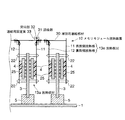
図8にモジュール群の一例を示す。図8に示すモジュール群2は、3つのモジュール2a〜2cからなり、各モジュール2a〜2cは、メモリ基板3と、メモリ基板3の表裏両面に、該基板3の長手方向に沿って配列された複数のメモリ素子4を有する(一般的には16個)。また、各モジュール2a〜2cのメモリ基板3は、マザーボード1の上に一定間隔で設けられたコネクタ5に挿入されている。
FIG. 8 shows an example of a module group. The module group 2 shown in FIG. 8 includes three modules 2 a to 2 c, and each module 2 a to 2 c is arranged along the longitudinal direction of the
図8に示す構成では、各モジュール2a〜2cに設けられているメモリ素子4から発生した熱は、メモリ素子4の表面からの熱放射と対流とによって放熱されると共に、メモリ基板3及びコネクタ5を介してマザーボード1へ伝導し、該マザーボード1の表面からも放熱される。図8では、メモリ素子4の表面からの熱放射を矢印Xによって、対流を矢印Yによって、マザーボード1を介した放熱を矢印Zによってそれぞれ模式的に示してある。尚、特許文献1には、図8に示すメモリ基板3に相当する回路チップもしくはボードの周辺をこれらが収容されているケースの外部にまで突出させて放熱効果を高めた回路モジュールが開示されている。
In the configuration shown in FIG. 8, heat generated from the
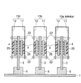
また、メモリ基板に設けられている複数のメモリ素子が一つずつ動作するRIMM(Rambus In-line Memory Module)では、複数のメモリ素子が同時に動作する他のメモリモジュールに比べて、1つのメモリ素子あたりの負荷が大きく、発熱量も大きくなる。そこで、図9に示すように、メモリ素子4から発生した熱をメモリ基板3の長手方向に逃がすための放熱板6が各モジュール2a〜2cに設けられている。この放熱板6は、各モジュール2a〜2cのメモリ基板3の表裏両面に、そこに設けられているメモリ素子4を取り囲むように配置され、対向するメモリ素子4に接触している。従って、あるモジュールのあるメモリ素子から発生した熱は、該メモリ素子が接触している放熱板を介して該メモリ素子が設けられているメモリ基板の長手方向(図9の紙面に垂直な方向)に分散されると共に、該放熱板6の表面から放熱される。
図8に示す構成によって実現される放熱では、モジュールの温度を所定値以下に維持することは困難である。特に、図8に示す3つのモジュールのうち、中央のモジュールに関しては、両外側のモジュールが障壁となって対流による放熱効果が低くなる。また、両外側のモジュールに設けられているメモリ素子から熱をもらうため、他に比べて温度が上昇する傾向にある。 With the heat dissipation realized by the configuration shown in FIG. 8, it is difficult to maintain the temperature of the module below a predetermined value. In particular, among the three modules shown in FIG. 8, with respect to the central module, the modules on the outer sides serve as a barrier, and the heat dissipation effect due to convection is reduced. Also, since heat is received from the memory elements provided in the modules on both outer sides, the temperature tends to rise compared to the others.
また、図9に示す構成では、各モジュール内における温度差は均一化されるかもしれないが、隣接する複数のモジュール間の温度差の均一化は図れない。特に、図9に示す3つのモジュールのうち、中央のモジュールの温度が他に比べて上昇する傾向があることは、上記図8に示す構成と同様である。実際、図9に示す3つのモジュールを同時に動作させ、各モジュールの温度を測定したところ、中央のモジュールの最高温度は67.2℃、両外側のモジュールの最高温度は61.6℃であり、5.0℃以上の温度差があった。 In the configuration shown in FIG. 9, the temperature difference in each module may be made uniform, but the temperature difference between adjacent modules cannot be made uniform. In particular, among the three modules shown in FIG. 9, the temperature of the central module tends to rise compared to the other modules, as in the configuration shown in FIG. In fact, when the three modules shown in Fig. 9 were operated simultaneously and the temperature of each module was measured, the maximum temperature of the central module was 67.2 ° C, and the maximum temperature of the outer modules was 61.6 ° C, which was over 5.0 ° C. There was a temperature difference.
以上のように、マザーボード等の上に複数モジュールが並列されている場合、各モジュール間の温度差が大きくなり、各モジュールのメモリ素子の特性パラメータ(セットアップ・ホールドタイム等)にバラツキが生じ、システム不良が発生することがある。また、メモリ素子の動作周波数は今後さらに増加することが予想され、その場合、メモリ素子が熱破壊を起こす危険性もある。 As described above, when multiple modules are arranged in parallel on a motherboard or the like, the temperature difference between the modules increases, and the characteristic parameters (setup and hold times, etc.) of the memory elements of each module vary, resulting in a system Defects may occur. In addition, the operating frequency of the memory element is expected to further increase in the future, and in that case, there is a risk that the memory element may be thermally destroyed.
本発明の目的は、複数のモジュールが隣接して並列されてなるモジュール群から発生した熱を効率的に放熱させると共に、モジュール群を構成する各モジュールの温度を均一化させることが可能なメモリモジュール放熱装置を提供することにある。 An object of the present invention is to efficiently dissipate heat generated from a module group in which a plurality of modules are adjacently arranged in parallel, and to make the temperature of each module constituting the module group uniform. The object is to provide a heat dissipation device.
上記目的を達成するための本発明のメモリモジュール放熱装置は、基板の表裏両面にメモリ素子がそれぞれ設けられたメモリモジュールが2つ以上並列されてなるメモリモジュール群から発生する熱を放熱させるメモリモジュール放熱装置であって、各メモリモジュールの基板の表面に設けられているメモリ素子に接触する表面側放熱板と該基板の裏面に設けられているメモリ素子に接触する裏面側放熱板とからなる放熱板対と、メモリモジュール毎に設けられた放熱板対間で熱伝導が行なわれるように、これら放熱板対同士を連結する放熱板対連結部材と、を有する。このため、メモリ素子から発生した熱は、そのメモリ素子が接触する放熱板の表面から放熱されると共に、放熱板対連結部材を介して他の放熱板対にも伝導し、メモリモジュール群全体の温度が均一化される。さらに、並列方向一端のメモリモジュールの基板表面に設けられているメモリ素子に接触する表面側放熱板の上部が、同メモリモジュールの基板裏面に設けられているメモリに素子に接触する裏面側放熱板の上端よりも上方に突出して突出部を形成し、並列方向他端のメモリモジュールの基板裏面に設けられているメモリ素子に接触する裏面側放熱板の上部が、同メモリモジュールの基板表面に設けられているメモリ素子に接触する表面側放熱板の上端よりも上方に突出して突出部を形成している。このため、メモリモジュールの数が増加した際には、前記突出部を利用して、既存の放熱板対に、新たな放熱板対を連結することができる。 To achieve the above object, a memory module heat dissipation device of the present invention is a memory module that dissipates heat generated from a memory module group in which two or more memory modules each provided with memory elements are provided in parallel on the front and back surfaces of a substrate. A heat dissipating device comprising a front surface heat dissipating plate in contact with a memory element provided on the surface of each memory module substrate and a back heat dissipating plate in contact with the memory element provided on the back surface of the substrate. a plate pair, so that thermal conduction is performed between the heat radiating plate pair provided for each memory module, that Yusuke heat radiating plate pair connecting member for connecting the radiator plate pairs together, the. For this reason, the heat generated from the memory element is radiated from the surface of the heat radiating plate with which the memory element is in contact, and is also conducted to other heat radiating plate pairs via the heat radiating plate pair connecting member. The temperature is made uniform. Further, the upper surface of the heat-radiating plate that contacts the memory element provided on the substrate surface of the memory module at one end in the parallel direction is in contact with the memory element provided on the back surface of the memory module. The upper surface of the back side heat sink that contacts the memory element provided on the back surface of the memory module at the other end in the parallel direction is provided on the front surface of the memory module. A protruding portion is formed so as to protrude upward from the upper end of the surface-side heat sink contacting the memory element. For this reason, when the number of memory modules increases, a new heat sink pair can be connected to an existing heat sink pair using the protrusions.
本発明のメモリモジュール放熱装置では、上記放熱板対を構成する表面側放熱板及び裏面側放熱板に密着させる固定手段や付勢手段を設けることもできる。 In the memory module heat dissipation device of the present invention, it is possible to provide a fixing means and an urging means that are in close contact with the front side heat sink and the back side heat sink constituting the heat sink pair.
また、放熱板対を構成する表面側放熱板、裏面側放熱板、及び放熱板対連結部材をすべて同一の材質とすることで、熱伝導率のさらなる向上を図ることもできる。 Further, the heat conductivity can be further improved by using the same material for the front surface side heat sink, the back surface side heat sink, and the heat sink pair connecting member constituting the heat sink pair.
さらに、メモリモジュール群を構成する各メモリモジュールが予め放熱板を供えている場合には、その放熱板の外側に、該放熱板に接触するように上記放熱板対を配置可能な構成とすることもできる。この場合、各メモリモジュールに何らの変更を加えることなく、メモリモジュールが予め備えている放熱板による放熱効果に加えて、本発明のメモリモジュール放熱装置による放熱が得られる。 Furthermore, when each memory module constituting the memory module group is provided with a heat sink in advance, the heat sink pair should be arranged outside the heat sink so as to be in contact with the heat sink. You can also. In this case, heat can be obtained by the memory module heat dissipating device of the present invention in addition to the heat dissipating effect by the heat dissipating plate provided in advance in the memory module without any change to each memory module.
加えて、上記放熱板対連結部材にスリットに形成して、放熱効果のさらなる向上を図ることもできる。 In addition, it is possible to further improve the heat dissipation effect by forming a slit in the heat dissipation plate pair connecting member.
本発明のメモリモジュール放熱装置は、メモリモジュール群を構成しているメモリモジュール毎に用意された複数の放熱板対と、複数の放熱板対間で熱伝導が行なわれるように、それら放熱板対を連結する放熱板対連結部材とを有している。従って、あるメモリモジュールが備えるメモリ素子から発生した熱がメモリモジュール群全体に分散されるので、複数のメモリモジュール間に大きな温度差が発生することがない。この結果、温度差に起因するメモリ素子の特性パラメータのバラツキが抑制される。 The memory module heat dissipation device of the present invention includes a plurality of heat sink pairs prepared for each memory module constituting the memory module group, and the heat sink pairs so that heat conduction is performed between the plurality of heat sink pairs. And a heat sink pair connecting member for connecting the two. Accordingly, since heat generated from the memory elements included in a certain memory module is dispersed throughout the memory module group, a large temperature difference does not occur between the plurality of memory modules. As a result, variations in the characteristic parameters of the memory element due to the temperature difference are suppressed.
(実施形態1)
以下、本発明のメモリモジュール放熱装置の実施形態の一例を図1及び図2に基づいて説明する。図1は、3つのメモリモジュール2a〜2cからなるメモリモジュール群2に装着された本発明のメモリモジュール放熱装置10を示す拡大断面図である。図2(a)は、メモリモジュール群に装着された本発明のメモリモジュール放熱装置10を示す平面図、(b)はメモリモジュール群に装着された本発明のメモリモジュール放熱装置10を示す一部切欠きの側面図である。尚、図2(b)では、図1に示すマザーボード1及びコネクタ5は便宜上省略されている。また、図1に示すメモリモジュール群2及びこのメモリモジュール群2を構成する各メモリモジュール2a〜2cは、図8に示すそれらと同一の構成を有する。そこで、同一の構成については同一の符号を付して説明を省略する。さらに、本例では、メモリ基板3の外面のうち、図1の右側の面を表面、左側の面を裏面と定義して説明をする。もっとも、かかる定義は単なる便宜上の定義に過ぎないことは勿論である。
(Embodiment 1)
Hereinafter, an example of an embodiment of a memory module heat dissipation device of the present invention will be described with reference to FIGS. 1 and 2. FIG. 1 is an enlarged sectional view showing a memory module heat dissipation device 10 of the present invention mounted on a memory module group 2 composed of three memory modules 2a to 2c. 2A is a plan view showing the memory module heat dissipation device 10 of the present invention mounted on the memory module group, and FIG. 2B is a part of the memory module heat dissipation device 10 of the present invention mounted on the memory module group. It is a side view of a notch. In FIG. 2B, the
図1に詳細に示すように、本発明のメモリモジュール放熱装置10は、一定間隔で対向する表面側放熱板11と裏面側放熱板12とから構成される3つの放熱板対13a〜13cと、これら3つの放熱板対13a〜13cを連結して一体化させる放熱板対連結部材14とを有する。ここで、各放熱板対13a〜13cを構成する表面側放熱板11及び裏面側放熱板12は、すべて平坦な金属製の薄板である。但し、放熱板対13aの表面側放熱板11は、その幅(W1)が対向する裏面側放熱板12の幅(W2)よりも若干広くなっている。一方、放熱板対13cの裏面側放熱板12は、その幅(W1)が対向する表面側放熱板11の幅(W2)よりも若干広くなっている。即ち、放熱板対13aと放熱板対13cとは、表面側放熱板11と裏面側放熱板12の関係が逆になっている。また、放熱板対13bの表面側放熱板11及び裏面側放熱板12は同一の幅を有し、その幅は放熱板対13aの裏面側放熱板12及び放熱板対13cの表面側放熱板11の幅(W2)と同一である。
As shown in detail in FIG. 1, the memory module heat dissipation device 10 of the present invention includes three heat
また、図2(b)に示すように、すべての表面側放熱板11及び裏面側放熱板12の長手方向両端の上下2箇所には、当該メモリモジュール放熱装置10をメモリモジュール群2に装着した際に、対応するメモリ基板3の略四隅に開口されている貫通孔20と連通する連通孔21が開口されている。
In addition, as shown in FIG. 2B, the memory module heat dissipation device 10 is mounted on the memory module group 2 at two locations on the upper and lower sides of all the front surface
再び図1を参照すると、放熱板対13aは、裏面側放熱板12の上端よりも(W1−W2)だけ上方に突出した表面側放熱板11の上部側面が放熱板対連結部材14の幅方向一方端面に当接され、上記表面側放熱板11と所定間隔を置いて対向する裏面側放熱板12の上端面が上記放熱板対連結部材14の裏面に当接されている。さらに、裏面側放熱板12の上端面と放熱板対連結部材14の裏面とが当接することによって形成された角部にL字形の固定部材15があてがわれ、あてがわれた固定部材15が留め具(クリップ16)によって裏面側放熱板12及び放熱板対連結部材14に固定されている。また、連通した表面側放熱板11の連通孔21、メモリ基板3の貫通孔20、及び裏面側放熱板12の連通孔21にはピン状の固定具22が挿入され、この固定具22によって表面側放熱板11及び裏面側放熱板12がメモリモジュール2aのメモリ基板3に固定され、メモリ素子4に密着している。
Referring again to FIG. 1, the
放熱板対13cは、表面側放熱板11の上端よりも(W1−W2)だけ上方に突出した裏面側放熱板12の上部側面が放熱板対連結部材14の幅方向他方端面に当接されている。また、表面側放熱板11と放熱板対連結部材14とは、放熱板対13aと同様に、固定部材15及びクリップ16によって固定されている。さらに、表面側放熱板11及び裏面側放熱板12は、放熱板対13a と同様に、固定具22によってメモリモジュール2cのメモリ基板3に固定されてメモリ素子4に密着している。
In the heat radiating
放熱板対13bは、所定間隔を置いて対向する表面側放熱板11及び裏面側放熱板12の上端面が上記放熱板対連結部材14の裏面にそれぞれ当接され、当接された表面側放熱板11及び裏面側放熱板12が固定部材15及びクリップ16によって放熱板対連結部材14にそれぞれ固定されている。さらに、表面側放熱板11及び裏面側放熱板12は、上記放熱板対13a及び13cと同様に、固定具22によってメモリモジュール2bのメモリ基板3に固定され、メモリ素子4に密着している。
In the
以上のように、当該メモリモジュール放熱装置10は、メモリモジュール群2に装着されると、各放熱板対13a〜13cが対応するメモリモジュール2a〜2cに被さると共に、各放熱板対13a〜13cを構成している表面側放熱板11及び裏面側放熱板12が連結されて一体化される。さらに、メモリモジュール2a〜2cに被せられた各放熱板対13a〜13cの表面側放熱板11及び裏面側放熱板12は、対向するメモリ基板3上に配列されているメモリ素子4の表面にそれぞれ面接触して密着する。
As described above, when the memory module heat dissipation device 10 is attached to the memory module group 2, the heat dissipation plate pairs 13a to 13c cover the corresponding memory modules 2a to 2c, and the heat dissipation plate pairs 13a to 13c are covered. The front
以上によって、いずれかのメモリモジュール2a〜2cのいずれかのメモリ素子4から発生した熱は該メモリ素子4に密着している表面側放熱板11又は裏面側放熱板12に伝導し、該メモリモジュール2a〜2c内で分散されると共に、放熱板対連結部材14を介して他の放熱板対13a〜13cにも伝導する。この結果、いずれかのメモリモジュール2a〜2cのいずれかのメモリ素子4から発生した熱は、メモリモジュール群2の全体に分散し、各メモリモジュール2a〜2c間に大きな温度差が生じることが抑制される。例えば、メモリモジュール2bのメモリ基板3の表面にあるメモリ素子4から発生した熱は、放熱板対13bの表面側放熱板11に伝導し、該放熱板11の長手方向に分散し、該放熱板11の表面から放熱される。また、同メモリ基板3の裏面にあるメモリ素子4から発生した熱は、放熱板対13bの裏面側放熱板12に伝導し、該放熱板12の長手方向に分散し、該放熱板12の表面から放熱される。さらに、表面側放熱板11に伝導した熱は放熱板対連結部材14に伝導し、該連結部材14の表面から放熱されると共に、主に放熱板対13aに伝導し、メモリモジュール2aにも伝導する。また、裏面側放熱板12に伝導した熱は放熱板対連結部材14に伝導し、該連結部材14の表面から放熱されると共に、主に放熱板対13cに伝導し、メモリモジュール2cにも伝導する。尚、メモリ素子4から発生した熱がメモリ基板3及びコネクタ5を介してマザーボード1に伝導し、マザーボード1の表面からも放熱されることは従来と同様である。図2に上記熱伝導の様子を一点鎖線の矢印を用いて模式的に示す。
As described above, the heat generated from any one of the
尚、図1に示すように、各放熱板対13a〜13cの表面側放熱板11及び裏面側放熱板12とメモリ素子4との間にシリコングリス25を塗布しておくと、表面側放熱板11及び裏面側放熱板12とメモリ素子4の表面との密着性が高まり熱伝導効率が向上する。また、表面側放熱板11及び裏面側放熱板12、及び放熱板対連結部材14をすべて同一材質とすることも、熱伝導効率向上の観点からは望ましい。この際に選択する材質としては、なるべく熱伝導率の高い材質が好ましく、例えば銅(Cu)が好適である。
As shown in FIG. 1, if
図1には、放熱板対が3つの場合を図示したが、メモリモジュールの数に応じて放熱板対を適宜増設することもできる。図3に、図1に示す放熱板対13aの右側に新たな放熱板対13eを増設した例を示す。この増設用の放熱板対13eは、放熱板対13aと同一の表面側放熱板11及び裏面側放熱板対12から構成され、図1に示す放熱板対連結部材14よりも幅が狭い増設用連結部材30によって放熱板対13aに連結されている。具体的には、増設用連結部材30の幅方向一端は上方に向けて折り曲げられており、その屈曲部31が、放熱板対13aの表面側放熱板11の突出部32(放熱板対連結部材14よりも上方に突出している部分)に突き合わされ、突き合わされた屈曲部31と突出部32とが連結用固定具33によって固定されている。ここで、増設用連結部材30よりも上方に突出している放熱板対13eの表面側放熱板11の上部は、さらに別の放熱板対を増設する際に、突出部32と同様に機能する。
Although FIG. 1 shows the case where there are three heat sink pairs, the heat sink pairs can be added as appropriate according to the number of memory modules. FIG. 3 shows an example in which a new heat sink pair 13e is added on the right side of the
尚、増設用の放熱板対13eを構成する表面側放熱板11及び裏面側放熱板12と増設用連結部材30との固定構造は、放熱板対13aにおける表面側放熱板11及び裏面側放熱板12と放熱板対連結部材14との固定構造と同一である。また、増設用の放熱板対13eを構成する表面側放熱板11及び裏面側放熱板12とメモリ基板3との固定構造も、放熱板対13aにおける表面側放熱板11及び裏面側放熱板12とメモリ基板3との固定構造と同一である。
In addition, the fixing structure of the front-
(実施形態2)
図4に本発明のメモリモジュール放熱装置の他の実施形態を示す。図4に示すメモリモジュール放熱装置10の基本構成は、図1に示すメモリモジュール放熱装置10と同一である。従って、同一の構成には同一の符号を付して説明を省略し、ここでは異なる点についてのみ説明する。
(Embodiment 2)
FIG. 4 shows another embodiment of the memory module heat dissipation device of the present invention. The basic configuration of the memory module heat dissipation device 10 shown in FIG. 4 is the same as that of the memory module heat dissipation device 10 shown in FIG. Therefore, the same components are denoted by the same reference numerals and description thereof is omitted, and only different points will be described here.
図4に示すメモリモジュール放熱装置10では、各放熱板対13a〜13cを構成する表面側放熱板11及び裏面側放熱板12とメモリ基板3とが弾性体(バネ40)によって連結されている。このため、各表面側放熱板11及び裏面側放熱板12は対向するメモリ基板3の側に引き寄せられるように付勢させ、メモリ基板4上のメモリ素子4の表面に密着する。
In the memory module heat dissipation device 10 shown in FIG. 4, the front surface side
尚、図1に示すメモリモジュール放熱装置10では、ピン状の固定具22を用いて表面側放熱板11及び裏面側放熱板12とメモリ基板3とを固定したが、上記構成を有する図4のメモリモジュール放熱装置10では、固定具22に相当する固定手段は不要となる。もっとも、図1に示す固定具22に加えて図4に示すバネ40を設けてもよい。この場合、連通した表面側放熱板11の連通孔、メモリ基板3の貫通孔、及び裏面側放熱板12の連通孔と、そこに挿通された固定具22とを固定せずにフリーの状態としておけば、固定具22は、バネ40の付勢による上記作用を何ら損なうことなく、表面側放熱板11、裏面側放熱板12及びメモリ基板3の位置ずれを規制する規制手段として機能する。
In the memory module heat radiating device 10 shown in FIG. 1, the front side
(実施形態3)
図5に本発明のメモリモジュール放熱装置の他の実施形態を示す。図5に示すメモリモジュール放熱装置の基本構成は、図1に示すメモリモジュール放熱装置10と同一である。従って、同一の構成には同一の符号を付して説明を省略し、ここでは異なる点についてのみ説明する。
(Embodiment 3)
FIG. 5 shows another embodiment of the memory module heat dissipation device of the present invention. The basic configuration of the memory module heat dissipation device shown in FIG. 5 is the same as that of the memory module heat dissipation device 10 shown in FIG. Therefore, the same components are denoted by the same reference numerals and description thereof is omitted, and only different points will be described here.
図5に示すメモリモジュールの主な特徴は、各メモリモジュール2a〜2cが予め放熱板6を備えているメモリモジュール群2に装着可能とするための改良が加えられている点である。具体的には、各メモリモジュール2a〜2cに、それらが備える放熱板6の外側から放熱板対13a〜13cをそれぞれ被せることができるように、各放熱板対13a〜13cを構成する表面側放熱板11と裏面側放熱板12の対向間隔が図1に示す放熱板対13a〜13cに比べて必要かつ十分なだけ拡大されている。より具体的には、各放熱板対13a〜13cを対応するメモリモジュール2a〜2cに被せたときに、各表面側放熱板11及び裏面側放熱板12が各モジュール2a〜2cの放熱板6に密着する間隔とされている。このとき、各表面側放熱板11及び裏面側放熱板12と各放熱板6との間にシリコングリス25を塗布しておくと、密着度が高まり熱伝導性が向上するので好ましい。
The main feature of the memory module shown in FIG. 5 is that each memory module 2a to 2c is improved so that it can be attached to the memory module group 2 including the
(実施形態4)
実施形態1〜3で説明したメモリモジュール放熱装置が備える放熱板対連結部材には、図6に示すようなスリット50を1つ又は2つ以上設けることができる。かかるスリット50を設けた場合、主に表面側放熱板11及び裏面側放熱板12から放熱された熱が該メモリモジュール放熱装置10の外部に放出され易くなり、放熱効果がさらに向上する。尚、図6に示す各スリット50の寸法は、5.0× 10.0mmであるが、スリット50の形状、寸法、及び配置は図示したものに限られない。
(Embodiment 4)
One or two or
実施形態1では、表面側放熱板、裏面側放熱板、及び放熱板対連結部材の材質としてCuを挙げたが、これらの材質はCuに限られるものではない。また、これらをすべて同一の材質で形成することも必須の条件ではない。
In
次に、本発明のメモリモジュール放熱装置の効果を確認すべく行なった試験の一例について説明する。この試験では、次の試料1〜試料3を用意した。
試料1:図1に示す本発明のメモリモジュール放熱装置が装着されたメモリモジュール群
試料2:本発明のメモリモジュールとは異なるメモリモジュール放熱装置が装着されたメモリモジュール群
試料3:放熱装置が装着されていないメモリモジュール群(図8に示すメモリモジュール群)
試料2のメモリモジュール放熱装置の構成を図7に示す。このメモリモジュール放熱装置は、図1に示すメモリモジュール放熱装置10(本発明のメモリモジュール放熱装置)が備えている放熱板対連結部材14を備えておらず、各放熱板対13a〜13cが独立している点を除いて、図1に示すメモリモジュール放熱装置10と同一の構成を有する。
Next, an example of a test conducted to confirm the effect of the memory module heat dissipation device of the present invention will be described. In this test, the following
Sample 1: Memory module group with memory module heat dissipation device of the present invention shown in FIG. 1 Sample 2: Memory module group with memory module heat dissipation device different from the memory module of the present invention Sample 3: Installation of heat dissipation device Memory module group (memory module group shown in FIG. 8)
The configuration of the memory module heat dissipation device of Sample 2 is shown in FIG. This memory module heat dissipation device does not include the heat dissipation plate
試験の条件その他の詳細は次の通りである。
各メモリモジュール2a〜2c:1GB Unb-DIMM
メモリ素子4:DDR SDRAM 512Mbit×8(16個)
単体パッケージ:TSOP
モジュール数:3(3枚差し)
メモリ素子4の動作周波数:DDR 333[MHz]
環境:自然対流下
コネクタ5間の間隔:11.0mm
モジュール2a〜2cの間隔(DIMM間隔):5.0mm
放熱板対13a〜13c及び放熱板対連結部材14の材質:銅
メモリ基板3の高さ(マザーボード1から基板3までの距離):30.48mm
放熱板対13a〜13cの高さ:50.8mm(マザーボード1から
放熱板対連結部材14までの距離)
測定対象:中央のメモリモジュール2bにおけるメモリ素子4の最高温度
(試験1)
試験1では、メモリ基板3の表裏両面に設けられているメモリ素子4のち、表面側又は裏面側の一方のメモリ素子4のみが集中的に動作する場合を想定し、次のように試料1〜試料3の各メモリモジュール2a〜2cの消費電力値を設定した。
メモリモジュール2b:メモリ基板の表面に設けられている8個のメモリ素子 542[mW]
メモリ基板の表面に設けられている8個のメモリ素子 58[mW]
メモリモジュール2a及び2c:16個すべてのメモリ素子 58[mW]
以上の条件で試料1〜試料3のメモリモジュール2bにおけるメモリ素子4の最高温度を測定したところ、次の測定結果が得られた。
試料1:59.8[℃]
試料2:63.3[℃]
試料3:80.5[℃]
以上の通り、試料1(図1に示す本発明のメモリモジュール放熱装置10)では、各放熱板が独立している試料2のメモリモジュール放熱装置に比べて、約4.0(63.3−59.8)[℃]も冷却効果が高いことが確認された。
The test conditions and other details are as follows.
Each memory module 2a-2c: 1GB Unb-DIMM
Memory element 4: DDR SDRAM 512Mbit x 8 (16 pieces)
Single package: TSOP
Number of modules: 3 (3 inserts)
Environment: Distance between natural convection connectors 5: 11.0mm
Module 2a to 2c spacing (DIMM spacing): 5.0mm
Material of the heat sink pairs 13a to 13c and the heat sink pair connection member 14: height of the copper memory board 3 (distance from the
Height of
Measurement object: Maximum temperature of the
In
Eight memory elements provided on the surface of the memory board 58 [mW]
When the maximum temperature of the
Sample 1: 59.8 [° C]
Sample 2: 63.3 [℃]
Sample 3: 80.5 [° C]
As described above, the sample 1 (the memory module heat dissipation device 10 of the present invention shown in FIG. 1) is about 4.0 (63.3-59.8) [° C.] compared to the memory module heat dissipation device of the sample 2 in which each heat dissipation plate is independent. ] Was also confirmed to have a high cooling effect.
(試験2)
試験2では、メモリ基板3の表裏両面に設けられているメモリ素子4が交互に動作する場合を想定し、次のように試料1〜試料3の各メモリモジュール2a〜2cの消費電力値を設定した。
メモリモジュール2b:メモリ基板の表面に設けられている8個のメモリ素子 300[mW]
メモリ基板の表面に設けられている8個のメモリ素子 300[mW]
メモリモジュール2a及び2c:16個すべてのメモリ素子 58[mW]
以上の条件で試料1〜試料3のメモリモジュール2bにおけるメモリ素子4の最高温度を測定したところ、次の測定結果が得られた。
試料1:58.4[℃]
試料2:62.4[℃]
試料3:75.1[℃]
ここでも、試料1(図1に示す本発明のメモリモジュール放熱装置10)では、各放熱板が独立している試料2のメモリモジュール放熱装置に比べて、約4.0(62.4−58.4)[℃]も冷却効果が高いことが確認された。
(Test 2)
In test 2, assuming that the
Eight memory elements on the surface of the memory board 300 [mW]
When the maximum temperature of the
Sample 1: 58.4 [° C]
Sample 2: 62.4 [° C]
Sample 3: 75.1 [° C]
Again, sample 1 (memory module heat dissipation device 10 of the present invention shown in FIG. 1) is approximately 4.0 (62.4-58.4) [° C.] compared to memory module heat dissipation device of sample 2 where each heat dissipation plate is independent. It was also confirmed that the cooling effect is high.
さらに、試験2と同一条件下で図6に示す本発明のメモリモジュール放熱装置10が装着されたメモリモジュール群におけるメモリ素子の最高温度を測定したところ、中央のメモリモジュールに設けられたメモリ素子の最高温度は57.6[℃]であった。すなわち、放熱板対連結部材14にスリット50を形成することで、さらに約1.0[℃]の冷却効果があることが確認された。
Further, when the maximum temperature of the memory elements in the memory module group in which the memory module heat dissipation device 10 of the present invention shown in FIG. 6 is mounted under the same conditions as in Test 2, the memory elements provided in the central memory module were measured. The maximum temperature was 57.6 [° C]. That is, it was confirmed that by forming the
1 マザーボード
2 メモリモジュール群
3 メモリ基板
4 メモリ素子
5 コネクタ
10 メモリモジュール放熱装置
11 表面側放熱板
12 裏面側放熱板
13 放熱板対
14 放熱板対連結部材
15 固定部材
16 クリップ
20 貫通孔
21 連通孔
22 固定具
25 シリコングリス
30 増設用連結部材
31 屈曲部
32 突出部
33 連結用固定具
40 バネ
50 スリット
DESCRIPTION OF
Claims (6)
各メモリモジュールの基板の表面に設けられているメモリ素子に接触する表面側放熱板と、該基板の裏面に設けられているメモリ素子に接触する裏面側放熱板とからなる放熱板対と、
メモリモジュール毎に設けられた前記放熱板対間で熱伝導が行なわれるように、これら放熱板対同士を連結する放熱板対連結部材と、を有し、
並列方向一端のメモリモジュールの基板表面に設けられているメモリ素子に接触する表面側放熱板の上部が、同メモリモジュールの基板裏面に設けられているメモリ素子に接触する裏面側放熱板の上端よりも上方に突出して突出部を形成し、
並列方向他端のメモリモジュールの基板裏面に設けられているメモリ素子に接触する裏面側放熱板の上部が、同メモリモジュールの基板表面に設けられているメモリ素子に接触する表面側放熱板の上端よりも上方に突出して突出部を形成している、メモリモジュール放熱装置。 A memory module heat dissipating device that dissipates heat generated from a memory module group in which two or more memory modules each provided with memory elements are provided in parallel on both front and back surfaces of a substrate,
A heat sink pair consisting of a front side heat sink that contacts the memory element provided on the surface of the substrate of each memory module, and a back side heat sink that contacts the memory element provided on the back surface of the substrate,
A heat sink pair connecting member that connects these heat sink pairs so that heat conduction is performed between the heat sink pairs provided for each memory module;
The upper part of the front-side heat sink that contacts the memory element provided on the substrate surface of the memory module at one end in the parallel direction is higher than the upper end of the rear-side heat sink that contacts the memory element provided on the rear face of the memory module substrate. Projecting upward to form a projection,
The upper end of the back surface side heat sink that contacts the memory element provided on the back surface of the memory module substrate at the other end in the parallel direction is the upper end of the front surface side heat sink plate that contacts the memory element provided on the surface of the memory module substrate. A memory module heat dissipating device that protrudes upward to form a protrusion .
前記基板の表面側に設けられた前記放熱板に接触する表面側放熱板と、前記基板の裏面側に設けられた前記放熱板に接触する裏面側放熱板とからなる放熱板対と、
メモリモジュール毎に設けられた前記放熱板対間で熱伝導が行なわれるように、これら放熱板対同士を連結する放熱板対連結部材と、を有し、
並列方向一端のメモリモジュールの基板表面側に設けられている放熱板に接触する表面側放熱板の上部が、同メモリモジュールの基板裏面側に設けられている放熱板に接触する裏面側放熱板の上端よりも上方に突出して突出部を形成し、
並列方向他端のメモリモジュールの基板裏面側に設けられている放熱板に接触する裏面側放熱板の上部が、同メモリモジュールの基板表面側に設けられている放熱板に接触する表面側放熱板の上端よりも上方に突出して突出部を形成している、メモリモジュール放熱装置。 A memory module heat dissipating device for dissipating heat generated from a memory module group in which two or more memory modules each provided with a memory element and heat dissipating plates for dissipating heat generated by the memory element are provided on both front and back surfaces of a substrate. There,
A heat sink pair consisting of a front side heat sink contacting the heat sink provided on the front side of the substrate and a back side heat sink contacting the heat sink provided on the back side of the substrate,
A heat sink pair connecting member that connects these heat sink pairs so that heat conduction is performed between the heat sink pairs provided for each memory module;
The upper part of the surface side heat sink that contacts the heat sink provided on the substrate surface side of the memory module at one end in the parallel direction is connected to the heat sink provided on the back side of the memory module substrate. Projecting upward from the upper end to form a projection,
The upper surface of the back side heat sink that contacts the heat sink provided on the back side of the memory module at the other end in the parallel direction is in contact with the heat sink provided on the front side of the memory module. A memory module heat dissipating device that protrudes upward from the upper end of the memory module.
Priority Applications (3)
| Application Number | Priority Date | Filing Date | Title |
|---|---|---|---|
| JP2003347404A JP3845408B2 (en) | 2003-10-06 | 2003-10-06 | Memory module heat dissipation device |
| US10/958,700 US7257002B2 (en) | 2003-10-06 | 2004-10-05 | Heat radiation device for memory module |
| US11/780,923 US7460373B2 (en) | 2003-10-06 | 2007-07-20 | Heat radiation device for memory module |
Applications Claiming Priority (1)
| Application Number | Priority Date | Filing Date | Title |
|---|---|---|---|
| JP2003347404A JP3845408B2 (en) | 2003-10-06 | 2003-10-06 | Memory module heat dissipation device |
Publications (2)
| Publication Number | Publication Date |
|---|---|
| JP2005116704A JP2005116704A (en) | 2005-04-28 |
| JP3845408B2 true JP3845408B2 (en) | 2006-11-15 |
Family
ID=34539992
Family Applications (1)
| Application Number | Title | Priority Date | Filing Date |
|---|---|---|---|
| JP2003347404A Expired - Fee Related JP3845408B2 (en) | 2003-10-06 | 2003-10-06 | Memory module heat dissipation device |
Country Status (2)
| Country | Link |
|---|---|
| US (2) | US7257002B2 (en) |
| JP (1) | JP3845408B2 (en) |
Families Citing this family (41)
| Publication number | Priority date | Publication date | Assignee | Title |
|---|---|---|---|---|
| US7552758B2 (en) * | 2004-10-29 | 2009-06-30 | International Business Machines Corporation | Method for high-density packaging and cooling of high-powered compute and storage server blades |
| US20060146497A1 (en) * | 2004-12-30 | 2006-07-06 | Intel Corporation | Heat exchanger for memory modules |
| US7289331B2 (en) * | 2005-03-30 | 2007-10-30 | International Business Machines Corporation | Interposable heat sink for adjacent memory modules |
| US7365990B2 (en) * | 2005-12-19 | 2008-04-29 | Infineon Technologies Ag | Circuit board arrangement including heat dissipater |
| DE102006012446B3 (en) * | 2006-03-17 | 2007-12-20 | Infineon Technologies Ag | Memory module with a means for cooling, method for producing the memory module with a means for cooling and data processing device comprising a memory module with a means for cooling |
| JP4921096B2 (en) * | 2006-09-28 | 2012-04-18 | 富士通株式会社 | Electronic equipment and cooling parts |
| US8018716B2 (en) | 2007-01-04 | 2011-09-13 | Whirlpool Corporation | Adapter for docking a consumer electronic device in discrete orientations |
| US8154857B2 (en) | 2007-01-04 | 2012-04-10 | Whirlpool Corporation | Appliance host with multiple service interfaces for coupling multiple consumer electronic devices |
| US7810343B2 (en) | 2007-01-04 | 2010-10-12 | Whirlpool Corporation | Dispenser with a service interface for a consumer electronic device |
| US7686127B2 (en) | 2007-01-04 | 2010-03-30 | Whirlpool Corporation | Acoustic chamber as part of adapter or appliance |
| US7870753B2 (en) | 2007-01-04 | 2011-01-18 | Whirlpool Corporation | Appliance door with a service interface |
| US7826203B2 (en) | 2007-01-04 | 2010-11-02 | Whirlpool Corporation | Transformative adapter for coupling a host and a consumer electronic device having dissimilar standardized interfaces |
| US7651368B2 (en) | 2007-01-04 | 2010-01-26 | Whirpool Corporation | Appliance with an adapter to simultaneously couple multiple consumer electronic devices |
| US7865639B2 (en) | 2007-01-04 | 2011-01-04 | Whirlpool Corporation | Appliance with an electrically adaptive adapter to alternatively couple multiple consumer electronic devices |
| US7765332B2 (en) | 2007-01-04 | 2010-07-27 | Whirlpool Corporation | Functional adapter for a consumer electronic device |
| US7898812B2 (en) | 2007-01-04 | 2011-03-01 | Whirlpool Corporation | Alternative hosts for multiple adapters and multiple consumer electronic devices |
| US7618295B2 (en) | 2007-01-04 | 2009-11-17 | Whirlpool Corporation | Adapter and consumer electronic device functional unit |
| US8010991B2 (en) * | 2007-01-29 | 2011-08-30 | Cisco Technology, Inc. | Policy resolution in an entitlement management system |
| JP4824624B2 (en) * | 2007-05-15 | 2011-11-30 | 株式会社リコー | Heat transfer member, heat transfer mechanism and information processing apparatus |
| TWM335716U (en) * | 2008-01-09 | 2008-07-01 | Walton Chaintech Corp | Heat dissipation structure for memory |
| US20090219687A1 (en) * | 2008-03-03 | 2009-09-03 | Jui-Nan Lin | Memory heat-dissipating mechanism |
| JP2009230505A (en) * | 2008-03-24 | 2009-10-08 | Fujitsu Ltd | Board unit and electronic apparatus |
| US7773378B2 (en) * | 2008-10-21 | 2010-08-10 | Moxa, Inc. | Heat-dissipating structure for expansion board architecture |
| US7643300B1 (en) * | 2008-12-16 | 2010-01-05 | Fu Zhun Precision Industry (Shen Zhen) Co., Ltd. | Heat dissipation device for memory module cards |
| US7821785B1 (en) * | 2009-04-20 | 2010-10-26 | Hewlett-Packard Development Company, L.P. | Heatsinks and a spring in a baffle slot between adjacent components |
| US8248805B2 (en) * | 2009-09-24 | 2012-08-21 | International Business Machines Corporation | System to improve an in-line memory module |
| US9245820B2 (en) | 2010-03-08 | 2016-01-26 | International Business Machines Corporation | Liquid DIMM cooling device |
| US8139355B2 (en) * | 2010-05-24 | 2012-03-20 | International Business Machines Corporation | Memory module connector having memory module cooling structures |
| JP2013069087A (en) * | 2011-09-22 | 2013-04-18 | Fujikura Ltd | Mounting structure of electronic component |
| JP5953734B2 (en) * | 2011-12-20 | 2016-07-20 | 富士通株式会社 | Heatsinks, stacked electronic devices, and electronic equipment. |
| TW201340854A (en) * | 2012-03-30 | 2013-10-01 | Ming-Yang Hsien | Memory module with heat dissipating apparatus |
| US8684757B2 (en) * | 2012-04-27 | 2014-04-01 | International Business Machines Corporation | Memory module connector with air deflection system |
| JP5949913B2 (en) * | 2012-05-24 | 2016-07-13 | 富士通株式会社 | Card-type electronic component cooling structure and electronic device |
| US9155194B1 (en) * | 2012-06-28 | 2015-10-06 | Emc Corporation | Memory interconnect arrangement having high data transfer speed signal integrity |
| US9437518B2 (en) | 2012-10-29 | 2016-09-06 | Samsung Electronics Co., Ltd. | Semiconductor module |
| HK1210376A2 (en) * | 2015-08-17 | 2016-04-15 | 馮文標 號 | Assembly structure of high-power semiconductor and heat sink |
| CN105390150A (en) * | 2015-12-02 | 2016-03-09 | 西安华为技术有限公司 | Storage device |
| WO2017131631A1 (en) * | 2016-01-26 | 2017-08-03 | Hewlett Packard Enterprise Development Lp | Electronic modules |
| US20180059744A1 (en) * | 2016-08-24 | 2018-03-01 | Intel Corporation | Liquid cooling interface for field replaceable electronic component |
| FR3065319B1 (en) * | 2017-04-13 | 2019-04-26 | Institut Vedecom | ELECTRONIC POWER MODULE AND ELECTRIC POWER CONVERTER INCORPORATING IT |
| USD960114S1 (en) | 2017-04-20 | 2022-08-09 | University Of Tennessee Research Foundation | Tampering detection enclosure |
Family Cites Families (16)
| Publication number | Priority date | Publication date | Assignee | Title |
|---|---|---|---|---|
| JPS6194399A (en) | 1984-10-15 | 1986-05-13 | 日本電信電話株式会社 | Circuit module |
| JPH05235255A (en) | 1992-02-25 | 1993-09-10 | Hitachi Ltd | Lamination multichip memory module |
| US5323292A (en) * | 1992-10-06 | 1994-06-21 | Hewlett-Packard Company | Integrated multi-chip module having a conformal chip/heat exchanger interface |
| DE4310446C1 (en) * | 1993-03-31 | 1994-05-05 | Export Contor Ausenhandelsgese | Power semiconductor circuit module - has mirror symmetrical configuration of power semiconductor carrier plates and heat sink elements |
| JP3224978B2 (en) | 1995-10-27 | 2001-11-05 | 富士通株式会社 | Semiconductor device |
| US6005771A (en) * | 1996-12-20 | 1999-12-21 | Trw Inc. | Electronics cooling technique for spacecraft modules |
| JP3996668B2 (en) | 1997-05-27 | 2007-10-24 | 富士通株式会社 | Socket for semiconductor device |
| JP3109479B2 (en) * | 1998-06-12 | 2000-11-13 | 日本電気株式会社 | Heat radiator and memory module equipped with heat radiator |
| JP2000164792A (en) | 1998-11-30 | 2000-06-16 | Hitachi Ltd | Semiconductor device and manufacture thereof |
| JP3831159B2 (en) | 1999-10-18 | 2006-10-11 | 日本圧着端子製造株式会社 | Electronic module with connector |
| JP2002093988A (en) | 2000-09-20 | 2002-03-29 | Nippon Avionics Co Ltd | Semiconductor integrated circuit package |
| JP2002110869A (en) | 2000-09-26 | 2002-04-12 | Toshiba Corp | Semiconductor device |
| US6421240B1 (en) * | 2001-04-30 | 2002-07-16 | Hewlett-Packard Company | Cooling arrangement for high performance electronic components |
| US6496375B2 (en) * | 2001-04-30 | 2002-12-17 | Hewlett-Packard Company | Cooling arrangement for high density packaging of electronic components |
| TWI229253B (en) * | 2003-01-08 | 2005-03-11 | Ma Lab Inc | Structural improvement for removable cooler |
| US6934152B1 (en) * | 2003-06-27 | 2005-08-23 | Emc Corporation | Systems and methods for connecting an electronic apparatus to a backplane |
-
2003
- 2003-10-06 JP JP2003347404A patent/JP3845408B2/en not_active Expired - Fee Related
-
2004
- 2004-10-05 US US10/958,700 patent/US7257002B2/en not_active Expired - Fee Related
-
2007
- 2007-07-20 US US11/780,923 patent/US7460373B2/en not_active Expired - Fee Related
Also Published As
| Publication number | Publication date |
|---|---|
| US7460373B2 (en) | 2008-12-02 |
| US7257002B2 (en) | 2007-08-14 |
| JP2005116704A (en) | 2005-04-28 |
| US20080013284A1 (en) | 2008-01-17 |
| US20050117303A1 (en) | 2005-06-02 |
Similar Documents
| Publication | Publication Date | Title |
|---|---|---|
| JP3845408B2 (en) | Memory module heat dissipation device | |
| US5276585A (en) | Heat sink mounting apparatus | |
| US20060221573A1 (en) | Heat sink for multiple semiconductor modules | |
| KR100833185B1 (en) | heatsink and memory module using the same | |
| KR101403901B1 (en) | Heat sink for dissipating heat | |
| US20070201212A1 (en) | Interposable Heat Sink for Adjacent Memory Modules | |
| TWI633831B (en) | Heat-dissipating device for expansion card and expansion card assembly with heat-dissipating function | |
| JP5522066B2 (en) | Optical communication card module | |
| US10721838B1 (en) | Stacked base heat sink with heat pipes in-line with airflow | |
| KR20110100522A (en) | Semiconductor module, socket for semiconductor module and connection structure thereof | |
| TWI721527B (en) | Electronic machine | |
| JP2001118984A (en) | Electronic module and electronic module with connector | |
| TWI553828B (en) | Integrated power module | |
| TWM538606U (en) | Motherboard assembly | |
| US6967843B2 (en) | System and method for dissipating heat from an electronic board | |
| JP2002289750A (en) | Multi-chip module and its radiation structure | |
| JP2007134472A (en) | Heat radiating plate and semiconductor device | |
| JP6021170B2 (en) | Cooling system | |
| US20090321050A1 (en) | Heat dissipation device | |
| US20050199377A1 (en) | Heat dissipation module with heat pipes | |
| US20090165997A1 (en) | Heat sink | |
| JP2004079940A (en) | Memory-module heat radiating device | |
| CN220753407U (en) | Power tube assembly and PCB assembly | |
| CN215181717U (en) | Main control cabinet | |
| CN220023172U (en) | Circuit board with heat radiation structure |
Legal Events
| Date | Code | Title | Description |
|---|---|---|---|
| A977 | Report on retrieval |
Free format text: JAPANESE INTERMEDIATE CODE: A971007 Effective date: 20051011 |
|
| A131 | Notification of reasons for refusal |
Free format text: JAPANESE INTERMEDIATE CODE: A131 Effective date: 20051019 |
|
| A521 | Request for written amendment filed |
Free format text: JAPANESE INTERMEDIATE CODE: A523 Effective date: 20051205 |
|
| RD04 | Notification of resignation of power of attorney |
Free format text: JAPANESE INTERMEDIATE CODE: A7424 Effective date: 20060203 |
|
| TRDD | Decision of grant or rejection written | ||
| A01 | Written decision to grant a patent or to grant a registration (utility model) |
Free format text: JAPANESE INTERMEDIATE CODE: A01 Effective date: 20060809 |
|
| A61 | First payment of annual fees (during grant procedure) |
Free format text: JAPANESE INTERMEDIATE CODE: A61 Effective date: 20060818 |
|
| R150 | Certificate of patent or registration of utility model |
Free format text: JAPANESE INTERMEDIATE CODE: R150 |
|
| FPAY | Renewal fee payment (event date is renewal date of database) |
Free format text: PAYMENT UNTIL: 20090825 Year of fee payment: 3 |
|
| FPAY | Renewal fee payment (event date is renewal date of database) |
Free format text: PAYMENT UNTIL: 20100825 Year of fee payment: 4 |
|
| FPAY | Renewal fee payment (event date is renewal date of database) |
Free format text: PAYMENT UNTIL: 20110825 Year of fee payment: 5 |
|
| FPAY | Renewal fee payment (event date is renewal date of database) |
Free format text: PAYMENT UNTIL: 20110825 Year of fee payment: 5 |
|
| FPAY | Renewal fee payment (event date is renewal date of database) |
Free format text: PAYMENT UNTIL: 20120825 Year of fee payment: 6 |
|
| FPAY | Renewal fee payment (event date is renewal date of database) |
Free format text: PAYMENT UNTIL: 20120825 Year of fee payment: 6 |
|
| FPAY | Renewal fee payment (event date is renewal date of database) |
Free format text: PAYMENT UNTIL: 20130825 Year of fee payment: 7 |
|
| R250 | Receipt of annual fees |
Free format text: JAPANESE INTERMEDIATE CODE: R250 |
|
| S111 | Request for change of ownership or part of ownership |
Free format text: JAPANESE INTERMEDIATE CODE: R313113 |
|
| R350 | Written notification of registration of transfer |
Free format text: JAPANESE INTERMEDIATE CODE: R350 |
|
| R250 | Receipt of annual fees |
Free format text: JAPANESE INTERMEDIATE CODE: R250 |
|
| LAPS | Cancellation because of no payment of annual fees |