JP3842047B2 - Intake stratification method in a direct injection internal combustion engine - Google Patents
Intake stratification method in a direct injection internal combustion engine Download PDFInfo
- Publication number
- JP3842047B2 JP3842047B2 JP2001015617A JP2001015617A JP3842047B2 JP 3842047 B2 JP3842047 B2 JP 3842047B2 JP 2001015617 A JP2001015617 A JP 2001015617A JP 2001015617 A JP2001015617 A JP 2001015617A JP 3842047 B2 JP3842047 B2 JP 3842047B2
- Authority
- JP
- Japan
- Prior art keywords
- intake
- combustion chamber
- intake air
- region
- stratification
- Prior art date
- Legal status (The legal status is an assumption and is not a legal conclusion. Google has not performed a legal analysis and makes no representation as to the accuracy of the status listed.)
- Expired - Fee Related
Links
Images


Classifications
-
- F—MECHANICAL ENGINEERING; LIGHTING; HEATING; WEAPONS; BLASTING
- F02—COMBUSTION ENGINES; HOT-GAS OR COMBUSTION-PRODUCT ENGINE PLANTS
- F02B—INTERNAL-COMBUSTION PISTON ENGINES; COMBUSTION ENGINES IN GENERAL
- F02B23/00—Other engines characterised by special shape or construction of combustion chambers to improve operation
- F02B23/02—Other engines characterised by special shape or construction of combustion chambers to improve operation with compression ignition
- F02B23/06—Other engines characterised by special shape or construction of combustion chambers to improve operation with compression ignition the combustion space being arranged in working piston
- F02B23/0672—Omega-piston bowl, i.e. the combustion space having a central projection pointing towards the cylinder head and the surrounding wall being inclined towards the cylinder center axis
-
- F—MECHANICAL ENGINEERING; LIGHTING; HEATING; WEAPONS; BLASTING
- F02—COMBUSTION ENGINES; HOT-GAS OR COMBUSTION-PRODUCT ENGINE PLANTS
- F02B—INTERNAL-COMBUSTION PISTON ENGINES; COMBUSTION ENGINES IN GENERAL
- F02B2275/00—Other engines, components or details, not provided for in other groups of this subclass
- F02B2275/14—Direct injection into combustion chamber
-
- F—MECHANICAL ENGINEERING; LIGHTING; HEATING; WEAPONS; BLASTING
- F02—COMBUSTION ENGINES; HOT-GAS OR COMBUSTION-PRODUCT ENGINE PLANTS
- F02B—INTERNAL-COMBUSTION PISTON ENGINES; COMBUSTION ENGINES IN GENERAL
- F02B23/00—Other engines characterised by special shape or construction of combustion chambers to improve operation
- F02B23/02—Other engines characterised by special shape or construction of combustion chambers to improve operation with compression ignition
- F02B23/06—Other engines characterised by special shape or construction of combustion chambers to improve operation with compression ignition the combustion space being arranged in working piston
- F02B23/0618—Other engines characterised by special shape or construction of combustion chambers to improve operation with compression ignition the combustion space being arranged in working piston having in-cylinder means to influence the charge motion
- F02B23/0621—Squish flow
-
- F—MECHANICAL ENGINEERING; LIGHTING; HEATING; WEAPONS; BLASTING
- F02—COMBUSTION ENGINES; HOT-GAS OR COMBUSTION-PRODUCT ENGINE PLANTS
- F02B—INTERNAL-COMBUSTION PISTON ENGINES; COMBUSTION ENGINES IN GENERAL
- F02B23/00—Other engines characterised by special shape or construction of combustion chambers to improve operation
- F02B23/02—Other engines characterised by special shape or construction of combustion chambers to improve operation with compression ignition
- F02B23/06—Other engines characterised by special shape or construction of combustion chambers to improve operation with compression ignition the combustion space being arranged in working piston
- F02B23/0618—Other engines characterised by special shape or construction of combustion chambers to improve operation with compression ignition the combustion space being arranged in working piston having in-cylinder means to influence the charge motion
- F02B23/0624—Swirl flow
-
- F—MECHANICAL ENGINEERING; LIGHTING; HEATING; WEAPONS; BLASTING
- F02—COMBUSTION ENGINES; HOT-GAS OR COMBUSTION-PRODUCT ENGINE PLANTS
- F02F—CYLINDERS, PISTONS OR CASINGS, FOR COMBUSTION ENGINES; ARRANGEMENTS OF SEALINGS IN COMBUSTION ENGINES
- F02F1/00—Cylinders; Cylinder heads
- F02F1/24—Cylinder heads
- F02F2001/244—Arrangement of valve stems in cylinder heads
- F02F2001/247—Arrangement of valve stems in cylinder heads the valve stems being orientated in parallel with the cylinder axis
-
- Y—GENERAL TAGGING OF NEW TECHNOLOGICAL DEVELOPMENTS; GENERAL TAGGING OF CROSS-SECTIONAL TECHNOLOGIES SPANNING OVER SEVERAL SECTIONS OF THE IPC; TECHNICAL SUBJECTS COVERED BY FORMER USPC CROSS-REFERENCE ART COLLECTIONS [XRACs] AND DIGESTS
- Y02—TECHNOLOGIES OR APPLICATIONS FOR MITIGATION OR ADAPTATION AGAINST CLIMATE CHANGE
- Y02T—CLIMATE CHANGE MITIGATION TECHNOLOGIES RELATED TO TRANSPORTATION
- Y02T10/00—Road transport of goods or passengers
- Y02T10/10—Internal combustion engine [ICE] based vehicles
- Y02T10/12—Improving ICE efficiencies
Landscapes
- Engineering & Computer Science (AREA)
- Chemical & Material Sciences (AREA)
- Combustion & Propulsion (AREA)
- Mechanical Engineering (AREA)
- General Engineering & Computer Science (AREA)
- Combustion Methods Of Internal-Combustion Engines (AREA)
- Exhaust-Gas Circulating Devices (AREA)
- Output Control And Ontrol Of Special Type Engine (AREA)
- Electrical Control Of Air Or Fuel Supplied To Internal-Combustion Engine (AREA)
Description
【0001】
【発明の属する技術分野】
本発明は、燃料を燃焼室に噴射する直接噴射式内燃機関において、燃焼室の吸気を成層化する方法に関する。
【0002】
【従来の技術】
排気還流装置を備えた直接噴射式圧縮着火内燃機関において、特開平11−148429号公報に開示されているように、排気中の有害物質を低減するため、燃焼室の吸気を成層化する技術が提案されている。
【0003】
燃焼室は、同一方向のスワール流を同心状に形成する2個の吸気ポートを設け、スワール流の上流側の吸気ポートでは、燃焼室の中心部に小径のスワール流を、下流側の吸気ポートでは、燃焼室の周辺部に大径のスワール流を形成する。
【0004】
上流側の吸気ポートを通過する吸気には還流排気を混入し、下流側の吸気ポートを通過する吸気には還流排気を混入せず、燃焼室中心部の円柱状領域には、還流排気を混入した吸気を、燃焼室周辺部の円環状領域には、還流排気を混入しない吸気を配置する。
【0005】
【発明が解決しようとする課題】
ところが、上記の従来技術においては、燃焼室に小径のスワール流と大径のスワール流を内外に形成するとしているが、スワール流は、径を拡大させる遠心力があるので、小径のスワール流は、遠心力によって外側に拡大し、燃焼室の周壁によって径が拡大しない大径のスワール流と衝突して混合することになる。従って、燃焼室の中心部の円柱状領域と周辺部の円環状領域に、組成の異なる吸気を配置することは困難である。
【0006】
また、吸気行程において、燃焼室に小径と大径のスワール流が内外に形成されたとしても、次の圧縮行程には、ピストン頂面の周辺部上の吸気がピストン頂面の中央部のキャビティに流入するスキッシュ流が発生するので、燃焼室周辺部の大径のスワール流は、スキッシュ流によって燃焼室中心側に運ばれ、燃焼室中心部の小径のスワール流と衝突して混合することになる。従って、吸気行程において形成した吸気の内外の成層状態を圧縮行程の終期近傍まで維持することは困難である。
【0007】
結局、燃料が燃焼室に噴霧されて燃焼を開始する圧縮行程の終期近傍の時点では、組成の異なる吸気が燃焼室の中心部の円柱状領域と周辺部の円環状領域に配置されているものとは認められない。
【0008】
燃焼室の吸気が燃料の燃焼開始時に所望の状態に成層化されていなければ、燃焼室における燃料の燃焼を所望の通りに制御することができない。
【0009】
【課題を解決するための着眼と研究】
1)直接噴射式圧縮着火内燃機関において、燃焼室の吸気中に燃料噴射弁から噴射された燃料流は、根元側部分では、その周囲の空気を燃料流内部に巻き込むと共に、その周囲の空気を燃料流外周に連行し、燃料流に随伴する空気流を誘起する。
【0010】
また、燃焼室の吸気中に噴射された燃料流は、高速で飛翔しながら、分裂して微粒化し、蒸気になり、蒸気になる先端側部分で燃焼して火炎を生ずる。なお、燃料流は、先端側部分より根元側で燃焼して火炎を生ずる場合もあるが、高温の火炎が大規模に発生する部分は、燃料流の先端側部分である。
【0011】
燃焼室は、燃料を噴射して燃焼している間、燃料流の根元側に、燃料と空気を混合して混合気を形成する混合気形成領域が形成されると共に、燃料流の先端側に、混合気が激しく燃焼して高温の火炎が大規模に発生する火炎発生領域が形成され、混合気形成領域と火炎発生領域に大別される。
【0012】
燃焼室の混合気形成領域において形成される混合気の組成は、燃料噴射時ないし燃焼開始時に、混合気形成領域に存在する吸気の組成に影響される。
【0013】
また、燃焼室の混合気形成領域で形成された混合気は、燃料流ないし混合気流によって燃焼室の火炎発生領域に運ばれる。燃焼室の火炎発生領域は、混合気形成領域から火炎発生領域に運ばれた混合気と、燃焼開始前から火炎発生領域に存在した吸気、及び、火炎発生領域で燃料の燃焼により発生した気体が存在することになり、それらが混在した状態の中で燃料の燃焼が行われる。燃焼室の燃料の燃焼状態は、燃焼開始時に、火炎発生領域に存在する気体の組成に影響される。
【0014】
換言すると、燃料噴射時ないし燃焼開始時に燃焼室の混合気形成領域に存在する気体に、所望の混合気を形成するのに適した組成の気体を選択すると共に、燃焼開始時に燃焼室の火炎発生領域に存在する気体に、所望の燃焼状態を発生させるのに適した組成の気体を選択すると、燃焼室の燃料の燃焼状態を所望の通りに制御することができる。
【0015】
即ち、燃焼室の吸気を混合気形成領域と火炎発生領域に成層化することにより、燃焼室の燃料の燃焼状態を制御することができる。
【0016】
2)燃料流の先端側部分において大規模な高温火炎の発生が始まる火炎発生開始位置は、燃料噴射弁の噴口から燃料流の分裂開始位置までの距離を噴霧分裂距離とすると、燃料噴射弁噴口位置から噴霧分裂距離の1〜1.5倍位離れた位置になる。なお、噴霧分裂距離=15.8(燃料密度/空気密度)1/2・(燃料噴射弁噴口径)である。
【0017】
また、燃料噴射弁は、ピストン頂面と対面する燃焼室天井面の中心部に多数の噴口を配置し、噴射方向は、多数であって放射方向であり、燃焼室の半径方向からピストン頂面側に傾斜し、圧縮行程の終期近傍においてピストン頂面中央部のキャビティの周辺部に向かう。
【0018】
従って、燃焼室の火炎発生領域は、各燃料噴射方向には燃焼室の燃料噴射弁噴口位置から噴霧分裂距離の約1〜1.5倍以上離れた領域になり、燃焼室の中心軸に対してほぼ対称になる。混合気形成領域は、各燃料噴射方向には燃焼室の燃料噴射弁噴口位置から噴霧分裂距離の約1〜1.5倍以内の領域になり、燃焼室の中心軸に対してほぼ対称になる。
【0019】
これらのことから、燃料が燃焼を開始する圧縮行程の終期近傍において、燃料が噴射される燃焼室の天井面中心部を中心とする概略半球面ないし概略扁平半球面の内側の領域と外側の領域に燃焼室の吸気を成層化することができると、上記の内側の領域と外側の領域にそれぞれ所望の組成の吸気を配置することにより、燃料の燃焼状態を制御することができる。
【0020】
3)複数の吸気ポートで燃焼室に複数の同一方向の吸気スワール流を形成し、燃料を燃焼室にその天井面の中心部からピストン頂面中央部のキャビティの周辺部に向けて噴射する直接噴射式圧縮着火内燃機関において、燃焼室や吸気ポートの形状、従って、吸気のスキッシュ流やスワール流の流動特性を選択して吸気成層化装置を構成すると、吸気を次のように成層化することができる。
【0021】
吸気行程において、図2に例示するように、スワール流の下流側の吸気ポート3では、燃焼室1の上部にその周壁に沿う第1吸気11のスワール流を、上流側の吸気ポート4では、燃焼室1の下部にその周壁に沿う第2吸気12のスワール流を形成する。図4と図5に例示するように、燃焼室1において組成の異なる第1吸気11のスワール流と第2吸気12のスワール流が上下に配置された状態は、圧縮行程の中程まで継続される。
【0022】
スキッシュ流が発生する圧縮行程の後半において、ピストン頂面の周辺部上のスワール流は、スキッシュ流によってピストン頂面の中央部のキャビティ内に運ばれ、径の縮小に伴うスワール方向速度の増加による遠心力によって、キャビティの中心に向かわず、キャビティの周壁に沿って流れ、キャビティの底面に向かう。キャビティは、スキッシュ流の発生前には、全域に第2吸気が存在するが、スキッシュ流が発生すると、図6(a)(b)(c)に時間経過順に例示するように、中央領域に第1吸気11が流入し、周辺領域と底部領域のみに第2吸気12が存在することになる。
【0023】
燃料が燃焼を開始する圧縮行程の終期近傍においては、図1に例示するように、燃焼室1は、燃料が噴射される天井面中心位置を中心とする概略扁平半球面13内の領域には、第1吸気11が主に存在し、その外側の領域には、第2吸気12が主に存在することになる。燃料の燃焼開始時に燃焼室の燃料噴射位置を中心とする概略半球面ないし概略扁平半球面の内側の領域と外側の領域に、組成の異なる吸気11、12が成層化されることになる。
【0024】
4)排気還流装置を備えた直接噴射式圧縮着火内燃機関において、燃焼期間中に、燃料噴射弁から噴射される燃料流の根元側部分の周囲に、還流排気を分布させずに、新鮮空気を分布させると、燃料流ないし混合気流によってその先端部に新鮮空気が運ばれ、酸素不足状態で燃焼する燃料流先端部ないしキャビティ谷部に酸素が供給され、酸素濃度がスート(すす)生成抑制値以上に増加して、スートの生成が減少する。だだし、この時、酸素濃度がNOx(窒素酸化物)生成値までには上昇しないように制御する。また、理論空燃比近傍のリーン側領域で高温燃焼してNOxが発生する燃焼室のスキッシュエリアとキャビティ周辺部に、還流排気を混入した吸気を分布させると、酸素濃度、燃焼温度が低下して、NOxの生成が減少する。
【0025】
内燃機関の負荷が多くて燃料の噴射終了時期が遅いとき、又は、内燃機関の回転数が高くて逆スキッシュ流が強いときには、燃料は、燃焼室のキャビティ外に流出する割合が高くなり、キャビティ外で酸素不足状態で燃焼し、キャビティ内で酸素過剰状態で燃焼する。すると、キャビティ外で主にスートが発生し、キャビティ内で主にNOxが発生する。
【0026】
このようなときには、燃焼室の成層パターンを逆にし、燃料噴射位置を中心とする概略半球面ないし概略扁平半球面の内側の領域に、還流排気が混入している吸気又は還流排気濃度が濃い吸気を、その外側の領域に、還流排気が混入していない吸気又は還流排気濃度が薄い吸気を配置する。すると、燃焼室のキャビティ外、スキッシュエリアでは、酸素濃度が増加し、スートの生成が抑制されると同時にスートの酸化が促進されて、スートが減少する。だだし、この時、酸素濃度がNOx生成値までには上昇しないように制御して、NOxの増加を防ぐ。
【0027】
即ち、内燃機関の運転条件に応じて、燃焼室1の成層パターンを変更する必要がある。燃焼室1の成層度も変更する必要がある。
【0028】
図1〜図6に例示する内燃機関において、運転条件に応じて、スワール流の下流側の吸気ポート3を通過する第1吸気に混入される還流排気の量と、上流側の吸気ポート4を通過する第2吸気に混入される還流排気の量をそれぞれ増減すると、燃焼室1の成層パターンは、変更される。燃焼室1の概略扁平半球面13内の領域でその外側の領域より還流排気の濃度が低くなる正成層パターンになる。また、燃焼室1の概略扁平半球面13内の領域でその外側の領域より還流排気の濃度が高くなる逆成層パターンになる。更に、燃焼室1の概略扁平半球面13内の領域とその外側の領域で還流排気の濃度が等しくなる均質パターンになる。
【0029】
また、内燃機関の運転条件に応じて、第1吸気に混入される還流排気の量と、第2吸気に混入される還流排気の量をそれぞれ増減すると、燃焼室1の成層度が変更される。概略扁平半球面13内の還流排気濃度に対する、概略扁平半球面13外の還流排気濃度の比、成層度が増減する。
【0030】
【課題を解決するための手段】
1)複数の吸気ポートで燃焼室に複数の同一方向の吸気スワール流を形成し、燃料を燃焼室にそのピストン頂面と対面する天井面の中心部からピストン頂面中央部のキャビティの周辺部に向けて噴射する直接噴射式内燃機関において、
複数の吸気スワール流は、特定成分の濃度が異なる第1吸気と第2吸気にし、
吸気行程において、燃焼室の上部にその周壁に沿う第1吸気のスワール流を形成し、燃焼室の下部にその周壁に沿うスワール流を形成し、圧縮行程の中程まで、燃焼室において第1吸気のスワール流と第2吸気のスワール流が上下に配置された状態を継続し、
スキッシュ流が発生する圧縮行程の後半に、ピストン頂面中央部のキャビティにおいて、中央領域に第1吸気を流入させ、周辺領域と底部領域に第2吸気を残存させ、
燃料が燃焼を開始する圧縮行程の終期近傍において、燃焼室の燃料噴射位置を中心とする概略半球面ないし概略扁平半球面の内側の領域に第1吸気を、外側の領域に第2吸気を主に配置し、内側の領域と外側の領域に、特定成分の濃度が異なる吸気を配置することを特徴とする吸気成層化方法。
【0031】
2)上記の吸気成層化方法において、
直接噴射式内燃機関の運転条件に応じて、燃焼室の成層パターンを、上記の内側の領域で上記の外側の領域より吸気の特定成分の濃度が低くなる正成層パターン、上記の内側の領域で上記の外側の領域より吸気の特定成分の濃度が高くなる逆成層パターン、又は、上記の内側の領域と上記の外側の領域で吸気の特定成分の濃度が等しくなる均質パターンに変更することを特徴とする。
【0032】
3)上記の吸気成層化方法において、
直接噴射式内燃機関の運転条件に応じて、燃焼室の成層度、上記の内側の領域における吸気の特定成分の濃度に対する、上記の外側の領域における吸気の特定成分の濃度の比を変更することを特徴とする。
【0034】
4)上記の吸気成層化方法において、
燃焼室の燃料噴射位置を中心とする概略半球面ないし概略扁平半球面は、燃料の噴射方向には燃焼室の燃料噴射位置から噴霧分裂距離の1〜1.5倍位離れていることを特徴とする。
【0035】
【発明の効果】
圧縮行程終期近傍の燃料の燃焼開始時に、燃焼室の燃料噴射位置を中心とする概略半球面ないし概略扁平半球面の内側の領域と外側の領域に、それぞれ、所望の組成の吸気、所望の成分濃度の吸気を配置し、燃料の燃焼状態を制御することができる。
【0036】
【発明の実施の形態】
[第1例(図1〜図8参照)]
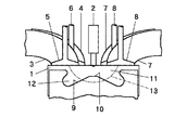
本例の吸気成層化装置を備えた直接噴射式圧縮着火内燃機関は、図1に示すように、燃焼室1の天井面の中心部に燃料噴射弁2の多数の噴口を配置し、燃焼室1の天井面の一側側に2個の吸気ポート3、4と吸気弁5、6を、他側側に2個の排気ポート7と排気弁8を設け、ピストン頂面の中央部に中心軸対称形状のキャビティ9を形成し、キャビティ9の底面中央部に山部10を設けている。
【0037】
燃料噴射弁2は、圧縮行程の終期近傍において、燃料を多数の噴口から放射方向にキャビティ9の周辺部に向けて噴射する。
【0038】
2個の吸気ポート3、4は、吸気行程において、図2に示すように、燃焼室1に吸気のスワール流11、12を同一方向に形成する。スワール流の下流側の吸気ポート3は、図2と図3に示すように、ヘリカルポート形状であり、吸気がほぼ燃焼室1天井面に沿う向きに流出し、燃焼室1の天井面側の上部にその周壁に沿う強い第1吸気のスワール流11を形成する。上流側の吸気ポート4は、タンジェンシャルポート形状であり、第1吸気のスワール流11との衝突を避けるため、吸気が斜め下向きに流出し、燃焼室1のピストン頂面側の下部にその周壁に沿う第2吸気のスワール流12を形成する。
【0039】
本例の吸気成層化装置においては、吸気行程に、図2に示すように、燃焼室1の上部と下部に、それぞれ、その周壁に沿う第1吸気のスワール流11、第2吸気のスワール流12を形成すると、吸気行程の終期に、図4に示すように、燃焼室1に第1吸気のスワール流11と第2吸気のスワール流12が上下に成層化される。吸気行程の終期には、上流側の吸気ポート4から最後に流入した第2吸気12の最後尾部分が燃焼室1の上部に存在するため、第1吸気11と第2吸気12の境界面13は、ピストン頂面に平行する平面にならず、傾斜した凹凸曲面になる。
【0040】
燃焼室1の組成の異なる第1吸気11と第2吸気12は、時間の経過に従って混ざり合い、一方の吸気にのみ含まれていた成分が他方の吸気にも含まれるようになり、その成分の濃度が連続して変化する状態になるので、その成分の濃度がほぼ中間値になる面を第1吸気11と第2吸気12の境界面13とする。
【0041】
圧縮行程になると、第2吸気12の最後尾部分が燃焼室1の下部に移動し、第1吸気11と第2吸気12の混合が進行し、圧縮行程の中程には、図5に示すように、第1吸気11と第2吸気12の境界面13は、ピストン頂面に平行する平面に近づく。燃焼室1に第1吸気スワール流11と第2吸気スワール流12が上下に成層化された状態は、圧縮行程の中程まで継続する。
【0042】
スキッシュ流が発生する圧縮行程の後半には、ピストン頂面の周辺部上のスワール流は、スキッシュ流によってピストン頂面の中央部のキャビティ9内に運ばれ、径の縮小に伴うスワール方向速度の増加による遠心力によって、キャビティ9の中心に向かわず、キャビティ9の周壁に沿って流れ、キャビティ9の底面に向かう。キャビティ9内は、図6(a)(b)(c)に時間経過順に示すように、燃焼室1下部の第2吸気12が充満した状態から、中央領域に燃焼室1上部の第1吸気11が流入し、周辺領域と底部領域のみに第2吸気12が残る。
【0043】
燃料が燃料噴射弁2から噴射されて燃焼を開始する圧縮行程の終期近傍には、図1に示すように、燃焼室1の燃料が噴射される天井面中心部を中心とする概略扁平半球面13の内側の領域には、第1吸気11が主に存在し、その外側の領域には、第2吸気12が主に存在する。燃料の燃焼開始時に、燃焼室1の燃料噴射位置を中心とする概略扁平半球面13の内側の領域と外側の領域に吸気11、12が成層化される。
【0044】
上記の概略扁平半球面13は、燃料噴射方向の半径を噴霧分裂距離の1〜1.5倍位にすると、燃焼室1の混合気形成領域と火炎発生領域に吸気11、12が成層化される。
【0045】
圧縮行程の終期近傍において、第1吸気11のスワール流が強過ぎると、図7(a)に示すように、第1吸気11は、スキッシュ流によってキャビティ9の底面に運ばれる際、キャビティ9の周壁を下る逆トロイダル流になり、キャビティ9の底面に流入し、キャビティ9の周壁と底面に存在した第2吸気12をキャビティ9の中央部に押し退ける。
【0046】
本例においては、吸気11、12のスワール流とスキッシュ流が適度であるので、図7(b)に示すように、第1吸気11は、キャビティ9の山部10と周壁の中間部を下るトロイダル流になり、その中間部に存在した第2吸気12をキャビティ9の周辺領域と底部領域に押し退け、燃焼室1の燃料噴射位置を中心とする概略扁平半球面13の内外に吸気11、12が成層化される。
【0047】
本例の吸気成層化装置は、吸気11、12がこのように成層化されるように、吸気11、12のスキッシュ流やスワール流の流動特性を決定する燃焼室1や吸気ポート3、4の形状を選択している。これらの形状によって吸気11、12の成層の度合いや境界面13の形状寸法を制御することができる。
【0048】
上記の形状には、燃焼室1のキャビティ9形状、ピストン頂面周辺部と天井面周辺部との間の間隔や、天井面からの吸気弁5、6下面の凹み量が例示される。
【0049】
模擬実験例
本例の吸気成層化装置において、燃焼室1に下流側の吸気ポート3から流入する第1吸気11を新鮮空気100%にし、上流側の吸気ポート4から流入する第2吸気12を新鮮空気50%と還流排気50%にした場合について、圧縮行程の終期における燃焼室1の還流排気濃度の分布を数値計算により求めた。
【0050】
図8はその結果を示し、同図(b)は下流側と上流側の吸気ポート3、4の間を通る燃焼室1の中央縦断面、同図(a)はその中央縦断面に直交する中央縦断面における還流排気濃度(EGR率)の分布を明度で示す。
【0051】
これらの図から明らかなように、圧縮行程の終期に、燃焼室1の還流排気濃度分布の等高面が燃料噴射位置を中心とする概略扁平半球面状に現れ、燃料噴射位置に近付くに従って還流排気濃度が薄くなり、還流排気濃度の分布がほぼ軸対称になる。燃焼室1の吸気は、燃料噴射位置を中心とする概略扁平半球面の内外に吸気11、12が成層化されることを示している。
【0052】
[第2例(図9参照)]
本例の吸気成層化装置は、第1例のそれにおいて、吸気の成層度を高めるため、下流側と上流側の吸気ポート3、4で吸気弁5、6の開放期間をずらす。
【0053】
燃焼室1の上部に第1吸気11を流入させる下流側の吸気ポート3では、図9に示すように、吸気弁5を遅い時期に開いて遅い時期に閉じる。燃焼室1の下部に第2吸気12を流入させる上流側の吸気ポート4では、吸気弁6を早い時期に開いて早い時期に閉じる。
【0054】
吸気行程の前期には、上流側の吸気ポート4の吸気弁6のみが開放し、燃焼室1の下部に配置する第2吸気12のみが燃焼室1に流入する。吸気行程の中期には、両者の吸気ポート3、4の吸気弁5、6が開放して第1吸気11と第2吸気12が燃焼室1に流入する。吸気行程の後期には、下流側の吸気ポート3の吸気弁5のみが開放し、燃焼室1の上部に配置する第1吸気11のみが燃焼室1に流入する。
【0055】
下流側と上流側の吸気ポート3、4で吸気弁5、6の開放期間が一致する第1例の場合に比較して、吸気行程の終期に第1吸気11と第2吸気12が上下に成層化される度合いが高くなり、圧縮行程の終期に吸気11、12が燃料噴射位置を中心とする概略扁平半球面13の内外に成層化される度合いが高くなる。
【0056】
その他の点は、第1例におけるのと同様である。
【0057】
[第3例(図10参照)]
本例の吸気成層化装置は、第1例のそれにおいて、吸気の成層度を高めるため、上流側の吸気ポート4の片側のみから第2吸気12を燃焼室1に流入させる。
【0058】
上流側の吸気ポート4においては、吸気が斜め下向きに流出して燃焼室1の周壁に斜めに衝突し、燃焼室1下部の周壁に沿うスワール流になる。タンジェンシャルポート形状の吸気ポート4の燃焼室1周壁側部分を流出する吸気の方が、燃焼室1中心側部分を流出する吸気より、燃焼室1の周壁に衝突するまでの距離が短く、燃焼室1の下部に流入し易い。
【0059】
そこで、上流側の吸気ポート4は、図10に示すように、燃焼室1の周壁側部分と中心側部分に2分割する仕切り壁21を設け、吸気ポート4の燃焼室1周壁側部分に、還流排気のような特定成分の濃度を高くした第2吸気12を流し、吸気ポート4の燃焼室1周壁側部分から第2吸気12を燃焼室1の下部に流入させる。吸気ポート4の燃焼室1中心側部分には、上流側の吸気ポート3と同様に第1吸気11を流し、吸気ポート4の燃焼室1中心側部分から第1吸気11を燃焼室1に流入させる。
【0060】
吸気ポート4の燃焼室1周壁側部分から燃焼室1に流入する第2吸気12は、気流が細くなって、第1吸気11と混合し難くなる。
【0061】
上流側の吸気ポート4の全体から第2吸気12を燃焼室1に流入させる第1例の場合に比較して、吸気行程の終期に第1吸気11と第2吸気12が上下に成層化される度合いが高くなり、圧縮行程の終期に吸気11、12が燃料噴射位置を中心とする概略扁平半球面13の内外に成層化される度合いが高くなる。
【0062】
その他の点は、第1例におけるのと同様である。
【0063】
[第4例]
本例の吸気成層化装置は、第1例のそれにおいて、吸気の成層度を高めるため、燃焼室1の下部又は上部に吸気が流入し易いサブポートを設ける。
【0064】
第3例における、燃焼室1の下部に吸気が流入し易い吸気ポート4の燃焼室1周壁側部分と同様な補助吸気ポートを設け、補助吸気ポートから燃焼室1の下部に、特定成分の濃度を高くした第2吸気12を流入させる。
【0065】
[第5例(図11参照)]
本例の吸気成層化装置は、第1例のそれにおいて、内燃機関の運転条件に応じて、燃焼室1の吸気の成層パターンと成層度を変更する。
【0066】
第1例の内燃機関において、スワール流の下流側の吸気ポート3に接続した第1吸気通路23に、図11に示すように、第1流量制御弁24を介して第1排気還流通路25を接続し、また、上流側の吸気ポート4に接続した第2吸気通路26に、第2流量制御弁27を介して第2排気還流通路28を接続する。第1流量制御弁24の開度と第2流量制御弁27の開度をそれぞれ内燃機関の運転条件に応じて制御する装置29を設ける。
【0067】
内燃機関の運転条件に応じて、第1流量制御弁24の開度と第2流量制御弁27の開度をそれぞれ制御すると、下流側の吸気ポート3を通過する第1吸気に混入される還流排気の量と、上流側の吸気ポート4を通過する第2吸気に混入される還流排気の量がそれぞれ増減し、燃焼室1の成層パターンは、変更される。燃焼室1の概略扁平半球面13内の領域でその外側の領域より還流排気の濃度が低くなる正成層パターンになる。また、燃焼室1の概略扁平半球面13内の領域でその外側の領域より還流排気の濃度が高くなる逆成層パターンになる。更に、燃焼室1の概略扁平半球面13内の領域とその外側の領域で還流排気の濃度が等しくなる均質パターンになる。
【0068】
また、内燃機関の運転条件に応じて、第1流量制御弁24の開度と第2流量制御弁27の開度をそれぞれ制御すると、燃焼室1の成層度が変更される。概略扁平半球面13内の還流排気濃度に対する、概略扁平半球面13外の還流排気濃度の比、具体的には、概略扁平半球面13内の燃料噴射位置の還流排気濃度に対する、概略扁平半球面13外のキャビティ底部周辺領域の還流排気濃度の比、成層度が増減する。
【図面の簡単な説明】
【図1】本発明の実施形態の第1例における吸気成層化装置を備えた直接噴射式圧縮着火内燃機関の概略縦断面図。
【図2】同内燃機関における吸気行程中程の燃焼室の概略斜視図。
【図3】同内燃機関における燃焼室の概略平面図。
【図4】同内燃機関における吸気行程終期の燃焼室の概略斜視図。
【図5】同内燃機関における圧縮行程中程の燃焼室の概略斜視図。
【図6】同内燃機関における圧縮行程終期近傍の燃焼室の概略縦断面図で、吸気の流動状態を示す図。
【図7】内燃機関における圧縮行程終期の燃焼室の概略縦断面図で、吸気の流動状態を示す図。
【図8】同内燃機関における模擬実験例の圧縮行程終期の吸気成層化状態を示す図。
【図9】実施形態の第2例における吸気成層化装置を備えた直接噴射式圧縮着火内燃機関の吸気弁揚程図。
【図10】第3例における吸気成層化装置を備えた直接噴射式圧縮着火内燃機関の燃焼室の概略平面図。
【図11】第5例における吸気成層化装置を備えた直接噴射式圧縮着火内燃機関の吸気通路部分の概略図。
【符号の説明】
1 燃焼室
2 燃料噴射弁
3 スワール流の下流側の吸気ポート
4 スワール流の上流側の吸気ポート
5 スワール流の下流側の吸気弁
6 スワール流の上流側の吸気弁
9 キャビティ
11 第1吸気
12 第2吸気
13 第1吸気と第2吸気の境界面、概略扁平半球面[0001]
BACKGROUND OF THE INVENTION
The present invention relates to a method for stratifying intake air in a combustion chamber in a direct injection internal combustion engine that injects fuel into the combustion chamber.To the lawRelated.
[0002]
[Prior art]
In a direct injection compression ignition internal combustion engine equipped with an exhaust gas recirculation device, as disclosed in Japanese Patent Laid-Open No. 11-148429, there is a technique for stratifying intake air in a combustion chamber in order to reduce harmful substances in exhaust gas. Proposed.
[0003]
The combustion chamber is provided with two intake ports that concentrically form a swirl flow in the same direction. In the intake port on the upstream side of the swirl flow, a small-diameter swirl flow is provided at the center of the combustion chamber, and the intake port on the downstream side. Then, a large-diameter swirl flow is formed in the periphery of the combustion chamber.
[0004]
Recirculation exhaust is mixed into the intake air passing through the upstream intake port, recirculation exhaust is not mixed into the intake air passing through the downstream intake port, and recirculation exhaust is mixed into the cylindrical region in the center of the combustion chamber. The intake air that does not mix the recirculated exhaust gas is disposed in the annular region around the combustion chamber.
[0005]
[Problems to be solved by the invention]
However, in the above prior art, a small-diameter swirl flow and a large-diameter swirl flow are formed inside and outside in the combustion chamber. However, since the swirl flow has a centrifugal force that expands the diameter, the small-diameter swirl flow Then, it expands outward due to centrifugal force, and collides with and mixes with a large-diameter swirl flow whose diameter does not expand due to the peripheral wall of the combustion chamber. Therefore, it is difficult to arrange intake air having different compositions in the cylindrical region at the center of the combustion chamber and the annular region at the periphery.
[0006]
In addition, even if a small diameter and large diameter swirl flow is formed inside and outside in the combustion chamber during the intake stroke, the intake air on the periphery of the piston top surface is in the center of the piston top surface in the next compression stroke. Therefore, the large-diameter swirl flow around the combustion chamber is transported to the combustion chamber center side by the squish flow and collides with the small-diameter swirl flow at the combustion chamber central portion. Become. Therefore, it is difficult to maintain the stratified state inside and outside the intake air formed in the intake stroke to the vicinity of the end of the compression stroke.
[0007]
Eventually, near the end of the compression stroke in which fuel is sprayed into the combustion chamber and starts combustion, intake air of different composition is arranged in the cylindrical region in the center of the combustion chamber and the annular region in the periphery It is not accepted.
[0008]
If the intake air in the combustion chamber is not stratified to a desired state at the start of fuel combustion, fuel combustion in the combustion chamber cannot be controlled as desired.
[0009]
[Focus and research to solve problems]
1) In a direct injection type compression ignition internal combustion engine, the fuel flow injected from the fuel injection valve during intake of the combustion chamber entrains the surrounding air inside the fuel flow at the base portion and Entrains the fuel flow perimeter and induces an air flow associated with the fuel flow.
[0010]
In addition, the fuel flow injected into the intake air of the combustion chamber flies at a high speed, breaks up and atomizes, becomes steam, and burns at the tip side portion that becomes steam, generating a flame. In some cases, the fuel flow burns closer to the root side than the tip side portion to generate a flame, but the portion where the high temperature flame is generated on a large scale is the tip side portion of the fuel flow.
[0011]
The combustion chamber is formed with an air-fuel mixture formation region in which fuel and air are mixed to form an air-fuel mixture on the base side of the fuel flow while fuel is injected and burned, and at the front end side of the fuel flow. In addition, a flame generation region is formed in which the air-fuel mixture burns vigorously and a high-temperature flame is generated on a large scale, and is broadly divided into a mixture generation region and a flame generation region.
[0012]
The composition of the air-fuel mixture formed in the air-fuel mixture formation region of the combustion chamber is affected by the composition of the intake air existing in the air-fuel mixture formation region at the time of fuel injection or combustion start.
[0013]
Further, the air-fuel mixture formed in the air-fuel mixture formation region of the combustion chamber is conveyed to the flame generation region of the combustion chamber by the fuel flow or the mixed air flow. The flame generation area of the combustion chamber consists of the air-fuel mixture carried from the mixture formation area to the flame generation area, the intake air existing in the flame generation area before the start of combustion, and the gas generated by the combustion of fuel in the flame generation area The fuel is burned in a state in which they exist. The combustion state of the fuel in the combustion chamber is affected by the composition of the gas present in the flame generation region at the start of combustion.
[0014]
In other words, a gas having a composition suitable for forming a desired air-fuel mixture is selected as the gas existing in the air-fuel mixture formation region of the combustion chamber at the time of fuel injection or at the start of combustion, and flame is generated in the combustion chamber at the start of combustion. When a gas having a composition suitable for generating a desired combustion state is selected as the gas existing in the region, the combustion state of the fuel in the combustion chamber can be controlled as desired.
[0015]
That is, the combustion state of the fuel in the combustion chamber can be controlled by stratifying the intake air in the combustion chamber into the mixture formation region and the flame generation region.
[0016]
2) The flame generation start position where the generation of a large-scale high-temperature flame starts at the front end portion of the fuel flow is defined as the fuel injection valve nozzle, where the distance from the fuel injection valve nozzle to the fuel flow split start position is the spray splitting distance. The position is 1 to 1.5 times the spray splitting distance from the position. Spray splitting distance = 15.8 (fuel density / air density)1/2-(Fuel injection valve nozzle diameter).
[0017]
In addition, the fuel injection valve has a large number of injection holes arranged at the center of the combustion chamber ceiling surface facing the piston top surface, and the injection directions are many and radial, and the piston top surface from the radial direction of the combustion chamber. In the vicinity of the end of the compression stroke, the piston heads toward the periphery of the cavity at the center of the top surface of the piston.
[0018]
Therefore, the flame generation region of the combustion chamber is a region separated from the fuel injection valve nozzle position of the combustion chamber by about 1 to 1.5 times or more of the spray splitting distance in each fuel injection direction, with respect to the central axis of the combustion chamber. Almost symmetrical. The air-fuel mixture formation region is a region within about 1 to 1.5 times the spray splitting distance from the fuel injection valve nozzle position of the combustion chamber in each fuel injection direction, and is substantially symmetric with respect to the central axis of the combustion chamber .
[0019]
Therefore, in the vicinity of the end of the compression stroke in which the fuel starts to burn, the inner and outer regions of the substantially hemispherical surface or the generally flat hemispherical surface centered on the center of the ceiling surface of the combustion chamber into which the fuel is injected. If the intake air in the combustion chamber can be stratified, the combustion state of the fuel can be controlled by disposing the intake air having a desired composition in the inner region and the outer region.
[0020]
3) A plurality of intake swirl flows in the same direction are formed in the combustion chamber by a plurality of intake ports, and fuel is directly injected into the combustion chamber from the center of the ceiling surface toward the periphery of the cavity at the center of the piston top surface. In an injection compression ignition internal combustion engine, when the intake stratification device is configured by selecting the shape of the combustion chamber and intake port, and thus the flow characteristics of the intake squish flow and swirl flow, the intake is stratified as follows: Can do.
[0021]
In the intake stroke, as illustrated in FIG. 2, at the
[0022]
In the latter half of the compression stroke in which the squish flow is generated, the swirl flow on the periphery of the piston top surface is carried by the squish flow into the cavity at the center of the piston top surface, and due to the increase in swirl speed as the diameter decreases. The centrifugal force does not go to the center of the cavity, but flows along the peripheral wall of the cavity and goes to the bottom surface of the cavity. Before the squish flow occurs, the second intake air exists in the entire area of the cavity. However, when the squish flow occurs, the cavities enter the central region as illustrated in the order of time passage in FIGS. 6 (a), 6 (b), and 6 (c). The
[0023]
In the vicinity of the end of the compression stroke in which the fuel starts to burn, as shown in FIG. 1, the
[0024]
4) In a direct injection compression ignition internal combustion engine equipped with an exhaust gas recirculation device, fresh air is distributed without distributing the recirculated exhaust gas around the base portion of the fuel flow injected from the fuel injection valve during the combustion period. When distributed, fresh air is carried to the tip by the fuel flow or mixed air flow, oxygen is supplied to the fuel flow tip or cavity valley that burns in an oxygen-deficient state, and the oxygen concentration is the soot generation suppression value. With this increase, soot generation decreases. However, at this time, control is performed so that the oxygen concentration does not rise to the NOx (nitrogen oxide) generation value. In addition, if the intake air mixed with the recirculated exhaust gas is distributed in the squish area of the combustion chamber where the NOx is generated by high-temperature combustion in the lean region near the stoichiometric air-fuel ratio and the cavity periphery, the oxygen concentration and the combustion temperature decrease. , NOx production is reduced.
[0025]
When the load of the internal combustion engine is heavy and the fuel injection end time is late, or when the internal combustion engine has a high rotational speed and a strong reverse squish flow, the ratio of the fuel flowing out of the cavity of the combustion chamber increases. It burns in an oxygen-deficient condition outside and burns in an oxygen-excess condition in the cavity. Then, soot is mainly generated outside the cavity, and NOx is mainly generated inside the cavity.
[0026]
In such a case, the stratification pattern of the combustion chamber is reversed, and the intake air in which the recirculated exhaust gas is mixed or the intake air having a high recirculated exhaust gas concentration in the region inside the substantially hemispherical surface or the generally flat hemispherical surface centered on the fuel injection position. In the region outside the intake air, the intake air in which the recirculated exhaust gas is not mixed or the intake air having a low recirculated exhaust gas concentration is arranged. Then, outside the cavity of the combustion chamber and in the squish area, the oxygen concentration increases, soot generation is suppressed, and at the same time, soot oxidation is promoted and soot is reduced. However, at this time, control is performed so that the oxygen concentration does not rise to the NOx generation value, thereby preventing an increase in NOx.
[0027]
That is, it is necessary to change the stratification pattern of the
[0028]
In the internal combustion engine illustrated in FIGS. 1 to 6, the amount of the recirculated exhaust gas mixed into the first intake air passing through the
[0029]
Further, when the amount of the recirculated exhaust gas mixed into the first intake air and the amount of the recirculated exhaust gas mixed into the second intake air are increased or decreased according to the operating conditions of the internal combustion engine, the stratification degree of the
[0030]
[Means for Solving the Problems]
1)A plurality of intake ports form the same swirl flow in the same direction in the combustion chamber,Fuel into the combustion chamberFrom the center of the ceiling facing the piston top to the periphery of the cavity at the center of the piston topIn a direct injection internal combustion engine for injection,
The plurality of intake swirl flows are the first intake and the second intake with different concentrations of specific components,
In the intake stroke, a swirl flow of the first intake along the peripheral wall is formed in the upper portion of the combustion chamber, a swirl flow along the peripheral wall is formed in the lower portion of the combustion chamber, and the first in the combustion chamber until the middle of the compression stroke. The state in which the swirl flow of the intake air and the swirl flow of the second intake air are arranged up and down continues,
In the latter half of the compression stroke in which the squish flow is generated, in the cavity at the central portion of the top surface of the piston, the first intake air is caused to flow into the central region and the second intake air is left in the peripheral region and the bottom region.,
Near the end of the compression stroke when the fuel begins to burn, A region inside a substantially hemispherical surface or a generally flat hemispherical surface centered on the fuel injection position of the combustion chamberThe first intake,In the outer areaThe second intake is mainly arranged, and intakes having different concentrations of specific components are arranged in the inner region and the outer region.Inhalation stratification characterized byMethod.
[0031]
2) In the above intake stratification method,
Depending on the operating conditions of the direct injection internal combustion engine, the stratification pattern of the combustion chamber is a positive stratification pattern in which the concentration of the specific component of the intake air is lower in the inner region than in the outer region. A reverse stratification pattern in which the concentration of the specific component of the intake air is higher than that in the outer region, or a uniform pattern in which the concentration of the specific component of the intake air is equal in the inner region and the outer region. And
[0032]
3) In the above intake stratification method,
The ratio of the concentration of the specific component of the intake air in the outer region to the concentration of the specific component of the intake air in the inner region is changed according to the operating conditions of the direct injection internal combustion engine. It is characterized by.
[0034]
4) The above intake stratification methodTo the lawLeave
The substantially hemispherical surface or the generally flat hemispheric surface centering on the fuel injection position of the combustion chamber is characterized by being 1 to 1.5 times the spray splitting distance from the fuel injection position of the combustion chamber in the fuel injection direction. And
[0035]
【The invention's effect】
At the start of combustion of fuel near the end of the compression stroke, intake of a desired composition is applied to the inner and outer regions of the approximately hemispherical surface to the generally flat hemispherical surface centered on the fuel injection position of the combustion chamber.Inhalation of the desired component concentrationAnd the combustion state of the fuel can be controlled.
[0036]
DETAILED DESCRIPTION OF THE INVENTION
[First example (see FIGS. 1 to 8)]
As shown in FIG. 1, the direct injection compression ignition internal combustion engine provided with the intake stratification device of this example has a large number of injection holes of a
[0037]
The
[0038]
The two
[0039]
In the intake stratification apparatus of this example, as shown in FIG. 2, in the intake stroke, the
[0040]
The
[0041]
In the compression stroke, the rearmost portion of the
[0042]
In the latter half of the compression stroke in which the squish flow is generated, the swirl flow on the periphery of the piston top surface is carried by the squish flow into the
[0043]
In the vicinity of the end of the compression stroke in which the fuel is injected from the
[0044]
When the radius in the fuel injection direction is about 1 to 1.5 times the spray splitting distance, the
[0045]
If the swirl flow of the
[0046]
In this example, since the swirl flow and squish flow of the
[0047]
The intake stratification device of this example is configured so that the
[0048]
Examples of the shape include the shape of the
[0049]
Simulation experiment example
In the intake stratification apparatus of this example, the
[0050]
FIG. 8 shows the result. FIG. 8B is a central longitudinal section of the
[0051]
As is clear from these figures, at the end of the compression stroke, the contour surface of the recirculated exhaust gas concentration distribution in the
[0052]
[Second example (see FIG. 9)]
In the intake stratification device of this example, in order to increase the stratification degree of intake air in the first example, the opening periods of the
[0053]
As shown in FIG. 9, in the
[0054]
In the first half of the intake stroke, only the
[0055]
Compared to the case of the first example in which the opening periods of the
[0056]
Other points are the same as in the first example.
[0057]
[Third example (see FIG. 10)]
The intake stratification device of this example is the same as that of the first example, and in order to increase the stratification of intake air, the
[0058]
In the
[0059]
Therefore, as shown in FIG. 10, the
[0060]
The
[0061]
Compared to the case of the first example in which the
[0062]
Other points are the same as in the first example.
[0063]
[Fourth example]
The intake stratification apparatus of this example is similar to that of the first example, and a subport is provided at the lower or upper part of the
[0064]
In the third example, an auxiliary intake port similar to the
[0065]
[Fifth example (see FIG. 11)]
The intake stratification apparatus of this example is the same as that of the first example, and changes the stratification pattern and degree of stratification of the intake air in the
[0066]
In the internal combustion engine of the first example, a first exhaust
[0067]
When the opening degree of the first flow
[0068]
Further, when the opening degree of the first flow
[Brief description of the drawings]
FIG. 1 is a schematic longitudinal sectional view of a direct injection compression ignition internal combustion engine equipped with an intake stratification device in a first example of an embodiment of the present invention.
FIG. 2 is a schematic perspective view of a combustion chamber in the middle of an intake stroke in the internal combustion engine.
FIG. 3 is a schematic plan view of a combustion chamber in the internal combustion engine.
FIG. 4 is a schematic perspective view of a combustion chamber at the end of an intake stroke in the internal combustion engine.
FIG. 5 is a schematic perspective view of a combustion chamber in the middle of a compression stroke in the internal combustion engine.
FIG. 6 is a schematic longitudinal sectional view of a combustion chamber near the end of a compression stroke in the internal combustion engine, showing a flow state of intake air.
FIG. 7 is a schematic longitudinal sectional view of a combustion chamber at the end of a compression stroke in an internal combustion engine, showing a flow state of intake air.
FIG. 8 is a view showing an intake stratification state at the end of a compression stroke in a simulation experiment example in the internal combustion engine.
FIG. 9 is an intake valve lift diagram of a direct injection compression ignition internal combustion engine equipped with an intake stratification device according to a second example of the embodiment.
FIG. 10 is a schematic plan view of a combustion chamber of a direct injection compression ignition internal combustion engine equipped with an intake stratification device in a third example.
FIG. 11 is a schematic view of an intake passage portion of a direct injection compression ignition internal combustion engine equipped with an intake stratification device in a fifth example.
[Explanation of symbols]
1 Combustion chamber
2 Fuel injection valve
3 Inlet port on the downstream side of the swirl flow
4 Inlet port upstream of swirl flow
5 Inlet valve downstream of swirl flow
6 Inlet valve upstream of swirl flow
9 cavity
11 First intake
12 Second intake
13 Boundary surface between first intake air and second intake air, roughly flat hemispherical surface
Claims (7)
複数の吸気スワール流は、特定成分の濃度が異なる第1吸気と第2吸気にし、
吸気行程において、燃焼室の上部にその周壁に沿う第1吸気のスワール流を形成し、燃焼室の下部にその周壁に沿うスワール流を形成し、圧縮行程の中程まで、燃焼室において第1吸気のスワール流と第2吸気のスワール流が上下に配置された状態を継続し、
スキッシュ流が発生する圧縮行程の後半に、ピストン頂面中央部のキャビティにおいて、中央領域に第1吸気を流入させ、周辺領域と底部領域に第2吸気を残存させ、
燃料が燃焼を開始する圧縮行程の終期近傍において、燃焼室の燃料噴射位置を中心とする概略半球面ないし概略扁平半球面の内側の領域に第1吸気を、外側の領域に第2吸気を主に配置し、内側の領域と外側の領域に、特定成分の濃度が異なる吸気を配置することを特徴とする吸気成層化方法。A plurality of intake ports form a plurality of intake swirl flows in the same direction in the combustion chamber, and fuel is directed from the center of the ceiling surface facing the piston top surface to the periphery of the cavity at the center of the piston top surface. In a direct injection internal combustion engine that injects
The plurality of intake swirl flows are the first intake and the second intake with different concentrations of specific components,
In inspiratory stroke, forming a first intake swirl flow along the peripheral wall at the top of the combustion chamber, forming a swirl flow along the peripheral wall in the lower part of the combustion chamber, to the middle of the compression stroke, the in the combustion chamber the state where the first intake swirl flow and a swirl flow of the second intake of are arranged vertically continuously,
In the latter half of the compression stroke of the squish flow is generated in the cavity of the piston top center, allowed to flow into the first intake in the central region, thereby leaving a second intake in the peripheral region and a bottom region,
In the vicinity of the end of the compression stroke at which the fuel starts to burn, the first intake air is mainly in the region inside the substantially hemispherical surface or the generally flat hemisphere centered on the fuel injection position in the combustion chamber, and the second intake air is mainly in the outer region. The intake stratification method is characterized by disposing intake air having different concentrations of specific components in the inner region and the outer region .
Priority Applications (1)
| Application Number | Priority Date | Filing Date | Title |
|---|---|---|---|
| JP2001015617A JP3842047B2 (en) | 2000-01-25 | 2001-01-24 | Intake stratification method in a direct injection internal combustion engine |
Applications Claiming Priority (3)
| Application Number | Priority Date | Filing Date | Title |
|---|---|---|---|
| JP2000-15634 | 2000-01-25 | ||
| JP2000015634 | 2000-01-25 | ||
| JP2001015617A JP3842047B2 (en) | 2000-01-25 | 2001-01-24 | Intake stratification method in a direct injection internal combustion engine |
Publications (2)
| Publication Number | Publication Date |
|---|---|
| JP2001280139A JP2001280139A (en) | 2001-10-10 |
| JP3842047B2 true JP3842047B2 (en) | 2006-11-08 |
Family
ID=26584087
Family Applications (1)
| Application Number | Title | Priority Date | Filing Date |
|---|---|---|---|
| JP2001015617A Expired - Fee Related JP3842047B2 (en) | 2000-01-25 | 2001-01-24 | Intake stratification method in a direct injection internal combustion engine |
Country Status (1)
| Country | Link |
|---|---|
| JP (1) | JP3842047B2 (en) |
Cited By (1)
| Publication number | Priority date | Publication date | Assignee | Title |
|---|---|---|---|---|
| US7987833B2 (en) | 2008-09-12 | 2011-08-02 | Hyundai Motor Company | Combustion system for vehicle |
Families Citing this family (3)
| Publication number | Priority date | Publication date | Assignee | Title |
|---|---|---|---|---|
| JP4715804B2 (en) * | 2007-05-09 | 2011-07-06 | トヨタ自動車株式会社 | Exhaust gas recirculation device for internal combustion engine |
| KR101745005B1 (en) * | 2011-10-07 | 2017-06-09 | 현대자동차주식회사 | Diesel - Gasoline Complex Engine |
| JP6014545B2 (en) * | 2013-05-14 | 2016-10-25 | 株式会社デンソー | Intake device for internal combustion engine |
Family Cites Families (2)
| Publication number | Priority date | Publication date | Assignee | Title |
|---|---|---|---|---|
| JPH06147023A (en) * | 1992-11-12 | 1994-05-27 | Yanmar Diesel Engine Co Ltd | Reflux method and reflux structure for exhaust gas in internal combustion engine |
| JP2001280140A (en) * | 2000-01-25 | 2001-10-10 | Toyota Central Res & Dev Lab Inc | Direct injection-type internal combustion engine |
-
2001
- 2001-01-24 JP JP2001015617A patent/JP3842047B2/en not_active Expired - Fee Related
Cited By (1)
| Publication number | Priority date | Publication date | Assignee | Title |
|---|---|---|---|---|
| US7987833B2 (en) | 2008-09-12 | 2011-08-02 | Hyundai Motor Company | Combustion system for vehicle |
Also Published As
| Publication number | Publication date |
|---|---|
| JP2001280139A (en) | 2001-10-10 |
Similar Documents
| Publication | Publication Date | Title |
|---|---|---|
| US6799551B2 (en) | Direct injection type internal combustion engine | |
| CN104981595B (en) | Piston for the cylinder of explosive motor | |
| US8464686B2 (en) | Diesel engine | |
| EP2529094B1 (en) | Direct injection diesel engines | |
| JP2007009722A (en) | Direct injection type spark-ignition internal combustion engine | |
| US10731544B2 (en) | Internal combustion engine and method for its operation | |
| JP3842047B2 (en) | Intake stratification method in a direct injection internal combustion engine | |
| JP2017194004A (en) | Combustion chamber structure of diesel engine | |
| CN209398492U (en) | Low heat waste diesel engine combustion chamber structure | |
| JP4385547B2 (en) | diesel engine | |
| JP2001280140A (en) | Direct injection-type internal combustion engine | |
| CN101769195B (en) | Combustion system of scattered space type direct injection diesel engine | |
| CN101793206B (en) | Direction-injection diesel engine combustion chamber | |
| JPH07208170A (en) | Auxiliary chamber structure in auxiliary chamber type engine | |
| EP0828066A1 (en) | Combustion chamber of diesel engine | |
| JP3903200B2 (en) | In-cylinder injection spark ignition internal combustion engine | |
| JP3191514B2 (en) | Subchamber engine | |
| JPH04292525A (en) | Direct injection type internal combustion engine | |
| JP2001317359A (en) | Internal combustion engine | |
| JP2526943Y2 (en) | Sub-chamber diesel engine | |
| JPH02301618A (en) | Combustion chamber structure of internal combustion engine | |
| JPH03264725A (en) | Subchamber type combustion chamber for internal combustion engine | |
| JPS63129116A (en) | Phase flow air charging system internal combustion engine | |
| JPS61106914A (en) | Combustion chamber in internal combustion engine | |
| JPH0143467Y2 (en) |
Legal Events
| Date | Code | Title | Description |
|---|---|---|---|
| A977 | Report on retrieval |
Free format text: JAPANESE INTERMEDIATE CODE: A971007 Effective date: 20041008 |
|
| A131 | Notification of reasons for refusal |
Free format text: JAPANESE INTERMEDIATE CODE: A131 Effective date: 20041026 |
|
| A521 | Written amendment |
Free format text: JAPANESE INTERMEDIATE CODE: A523 Effective date: 20041220 |
|
| A131 | Notification of reasons for refusal |
Free format text: JAPANESE INTERMEDIATE CODE: A131 Effective date: 20060404 |
|
| A521 | Written amendment |
Free format text: JAPANESE INTERMEDIATE CODE: A523 Effective date: 20060603 |
|
| A711 | Notification of change in applicant |
Free format text: JAPANESE INTERMEDIATE CODE: A711 Effective date: 20060608 |
|
| TRDD | Decision of grant or rejection written | ||
| A521 | Written amendment |
Free format text: JAPANESE INTERMEDIATE CODE: A821 Effective date: 20060608 |
|
| A01 | Written decision to grant a patent or to grant a registration (utility model) |
Free format text: JAPANESE INTERMEDIATE CODE: A01 Effective date: 20060725 |
|
| A61 | First payment of annual fees (during grant procedure) |
Free format text: JAPANESE INTERMEDIATE CODE: A61 Effective date: 20060809 |
|
| R150 | Certificate of patent or registration of utility model |
Free format text: JAPANESE INTERMEDIATE CODE: R150 |
|
| FPAY | Renewal fee payment (event date is renewal date of database) |
Free format text: PAYMENT UNTIL: 20100818 Year of fee payment: 4 |
|
| FPAY | Renewal fee payment (event date is renewal date of database) |
Free format text: PAYMENT UNTIL: 20110818 Year of fee payment: 5 |
|
| FPAY | Renewal fee payment (event date is renewal date of database) |
Free format text: PAYMENT UNTIL: 20120818 Year of fee payment: 6 |
|
| FPAY | Renewal fee payment (event date is renewal date of database) |
Free format text: PAYMENT UNTIL: 20120818 Year of fee payment: 6 |
|
| S531 | Written request for registration of change of domicile |
Free format text: JAPANESE INTERMEDIATE CODE: R313532 |
|
| FPAY | Renewal fee payment (event date is renewal date of database) |
Free format text: PAYMENT UNTIL: 20120818 Year of fee payment: 6 |
|
| R350 | Written notification of registration of transfer |
Free format text: JAPANESE INTERMEDIATE CODE: R350 |
|
| FPAY | Renewal fee payment (event date is renewal date of database) |
Free format text: PAYMENT UNTIL: 20120818 Year of fee payment: 6 |
|
| FPAY | Renewal fee payment (event date is renewal date of database) |
Free format text: PAYMENT UNTIL: 20130818 Year of fee payment: 7 |
|
| R250 | Receipt of annual fees |
Free format text: JAPANESE INTERMEDIATE CODE: R250 |
|
| LAPS | Cancellation because of no payment of annual fees |