JP3835882B2 - Indwelling needle assembly - Google Patents
Indwelling needle assembly Download PDFInfo
- Publication number
- JP3835882B2 JP3835882B2 JP09650497A JP9650497A JP3835882B2 JP 3835882 B2 JP3835882 B2 JP 3835882B2 JP 09650497 A JP09650497 A JP 09650497A JP 9650497 A JP9650497 A JP 9650497A JP 3835882 B2 JP3835882 B2 JP 3835882B2
- Authority
- JP
- Japan
- Prior art keywords
- needle
- tip
- hub
- needle tip
- inner needle
- Prior art date
- Legal status (The legal status is an assumption and is not a legal conclusion. Google has not performed a legal analysis and makes no representation as to the accuracy of the status listed.)
- Expired - Fee Related
Links
Images


Landscapes
- Infusion, Injection, And Reservoir Apparatuses (AREA)
Description
【0001】
【発明が属する技術分野】
本発明は留置針組立体に関し、特に例えば輸液の際に用いられる留置針組立体に関する。
【0002】
【従来の技術】
輸液等に用いられる留置針を使用する際、外針内に内針を収容した状態(内・外針一体の状態)でこれらを血管に穿刺し、次いで、外針が所定位置まで挿入された後内針は抜き取られ、外針に続く基端には輸液ラインが接続されて薬液等を流通させる。このような留置針としては、特開昭57−75660号公報に記載されたものが知られている。
【0003】
ここで、抜き取られた使用済みの内針は廃棄されることとなるが、術者や患者または廃棄作業者等が過って鋭利な針先に触れ、傷を負う場合がある。使用済みの針は、患者の血液や体液等で汚染されており、針創傷から肝炎や各種伝染性疾患等に感染するおそれがあり、よって、内針の取扱いは細心の注意を要するものである。
【0004】
このような問題を解決するために、特開昭2−99070号公報には、内針の針先を防護する針防護部品を設けた静脈カテーテルを開示している。この針防護部品は、内針に設けられた係合スロットにロックフランジを係合させ、内針の針先を覆うようにしたものである。
【0005】
しかし、このように内針に係合スロットを設けた場合、該スロット部分で内針の強度が低下するため、穿刺または廃棄の際にスロット部分で内針が屈曲または折れ易く使用し難いものであり、また折れた場合、その折針の回収は困難でかつ非常に危険である。
【0006】
また、係合スロットは内針の外壁面に刻設されるが、内針のような穿刺針は通常、ステンレス鋼等の硬質材料で形成されているため、このようなスロットの加工は困難である。さらに、係合スロットの深さは、内針の肉厚よりも小さくすることが必要であるが、この程度の深さのスロットでは針とフランジとのロック係合は確実なものとは言えない。特に、ロックフランジはゴム等の弾性材料で構成されているため、係合スロットにロックフランジの凸部が一旦係合しても、この凸部が弾性変形して容易にその係合が外れてしまうことがある。したがって、針先の防護部品としては不十分・不完全なものであった。
【0007】
【発明が解決しようとする課題】
本発明の目的は、内針の針先を容易かつ確実に被包することができ、かつ穿刺や廃棄等に支障がなく、安全性の高い留置針組立体を提供することにある。
【0008】
【課題を解決するための手段】
このような目的は、下記(1)〜(4)の本発明により達成される。
【0009】
(1) 外針ハブと、
前記外針ハブに固定された中空の外針と、
前記外針ハブに係止可能な内針ハブと、
前記内針ハブに固定され前記外針の内腔内に挿入可能な内針と、
前記外針ハブ内に離脱可能に嵌着され前記内針の針先を被包し得る針先被包部材と、
前記内針ハブと前記針先被包部材とを連結し、前記内針ハブを前記外針ハブに対し基端側へ移動させる際に加えられる引張力を針先被包部材に伝達する連結部材とを有する留置針組立体において、
前記針先被包部材は、前記内針が挿通可能な内腔を有し、かつその内腔内に前記内針の針先の先端側への戻りを防止し得る2つの針止部材を備えており、
前記各針止部材は、弾性材料で構成され、かつ前記内針を挿通可能な孔を有しており、その基端側の孔径は前記内針の外径よりも小さく、
前記内針ハブを前記外針ハブに対し基端側へ移動させ前記2つの針止部材の間に前記内針の針先を保持したとき、前記連結部材の引張力により前記針先被包部材が前記外針ハブから離脱するよう構成されていることを特徴とする留置針組立体。
【0010】
(2) 前記各針止部材は、先端側から基端側に向かって外径が漸減するテーパ部を有している上記(1)に記載の留置針組立体。
【0011】
(3) 前記連結部材は、前記内針の針先が前記針先被包部材で被包されたとき緊張状態となる線状体で構成される上記(1)または(2)に記載の留置針組立体。
【0012】
(4) 前記内針が前記針止部材に対し摺動する際の摩擦力は、前記外針ハブと前記針先被包部材との嵌着力よりも小さい上記(1)ないし(3)のいずれかに記載の留置針組立体。
【0019】
【発明の実施の形態】
以下、本発明の留置針組立体を添付図面に示す好適実施例に基づいて詳細に説明する。なお、図1〜図6において、図の右側を「基端」、左側を「先端」という。
【0020】
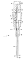
図1は本発明の留置針組立体の実施例を示す縦断面図、図2は図1に示す留置針組立体の針止部材の斜視図であり、図3は図1に示す留置針組立体の針先被包部材の縦断面図、図6は、本発明の留置針組立体の針先被包部材による針先の被包状態を示す縦断面図である。
【0021】
本発明の留置針組立体1は、外針ハブ3と、この外針ハブ3に固定された中空の外針2と、外針ハブ3に係止可能な内針ハブ6と、この内針ハブ6に固定され、前記外針2の内腔内に挿入可能な内針5と、前記外針ハブ3内に設置され、前記内針5の針先51を被包し得る針先被包部材7と、前記内針ハブ6と前記針先被包部材7とを連結し、前記内針ハブ6を前記外針ハブに対し基端側へ移動させる際に加えられる引張力を針先被包部材7に伝達し、内針5の針先51が針先被包部材7に被包されたとき該針先被包部材7を前記外針ハブ3から離脱させる連結部材9とで構成されている。
【0022】
以下、これらの各構成要素について順次説明する。
外針ハブ3は中空の管体で構成されおり、基端側には、後述する針先被包部材7を収容可能な収容部31が形成されている。また、収容部31の先端側には、収容部31より縮径した外針固定部32が一体的に形成されている。
【0023】
外針ハブ3の構成材料としては、例えば、ポリエチレン、ポリプロピレン、エチレン−酢酸ビニル共重合体等のポリオレフィン、ポリ塩化ビニル、ポリブタジエン、ポリアミド、ポリエステル等の各種樹脂材料が挙げられる。なお、内部の視認性を確保するために、これらは、透明または半透明な材料で構成されているのが好ましい。これにより、外針2が血管を確保したことを容易に確認することができる。
【0024】
外針ハブ3の外針固定部32には、外針2が図1に示すような例えば金属製のかしめ部材4によりかしめられて固定されている。
【0025】
かかる外針2は、中空管で構成され、図1に示すように先端部21は、生体への穿刺の際の抵抗および刺激を緩和するために外径が先端方向に向かって漸減するテーパ状に形成されている。
【0026】
外針2の構成材料としては、特に限定されないが、例えば、エチレン−テトラフルオロエチレン共重合体(ETFE)、ポリウレタン、ポリエーテルナイロン樹脂等の軟質樹脂が好ましい。この場合、内部の視認性を確保するために、外針2は、その全部または一部を透明または半透明な材料で構成することもできる。また、外針2の構成材料中に、例えば硫酸バリウムのようなX線造影剤を配合し、造影機能を持たせることもできる。
【0027】
内針ハブ6は、図1に示すように、その先端部には少なくとも内針5を挿入可能な孔62、内腔63を有している。この孔62には、内針5を挿通した状態で接着剤(または溶剤)61が充填されており、内針5を内針ハブ6に固定している。
【0028】
このような内針ハブ6の材料としては、前述した外針ハブ3と同様の材料を用いることができる。なお、内部の視認性を確保するために透明または半透明材料で構成されているのが好ましい。これによって内腔63への血液の流入により、内針5の針先51が血管を確保したことを容易に確認することができる。
【0029】
内針5は、外針2の内腔に挿入して使用されるもので、その外径は、外針2の内径より若干小さく設定されている。また、内針5の長さは、内針ハブ6を外針ハブ3の収容部31内で係止するまで挿入したとき、少なくとも針先51が外針2の先端部21の開口から突出できる程度の長さであることが好ましい。
【0030】
内針5の構成材料としては、例えば、ステンレス鋼、アルミニウムまたはアルミニウム合金、チタンまたはチタン合金のような金属材料で構成され、その先端部には、鋭利な針先(刃先)51が形成されている。この針先51は、内針5の軸線に対し所定角度傾斜した刃面を有している。
【0031】
収容部31内には、針先被包部材7が設けられている。
針先被包部材7は、内針5が挿通可能な内腔を有する管体71と、管体71の基端側に位置し、一体形成され針先被包部材7を収容部31の所定位置で支持・固定するための支持部(フランジ)72とを有している。
【0032】
この針先被包部材7を収容部31内に固定する方法は特に限定されず、例えば、支持部72と収容部31との接着、溶着、融着あるいは支持部72の弾性復元力を利用した圧着、嵌着等が挙げられるが、嵌着による固定が特に好ましい。これにより、針先被包部材7の着脱を容易に制御することができる。
【0033】
この針先被包部材7の構成材料としては、特に限定されないが可撓性を有する高分子材料が好ましく、例えば、ポリエチレン、ポリプロピレン、エチレン−プロピレン共重合体、エチレン−酢酸ビニル共重合体、架橋型エチレン−酢酸ビニル共重合体等のポリオレフィン、ポリエステル、ポリ塩化ビニル、ポリウレタン、ポリアミド、ポリアミドエラストマー等の熱可塑性樹脂、天然ゴム、シリコーンゴム等の弾性材料が挙げられる。
【0034】
また、針先被包部材7の管体71内には、図2に示すような円錐形または円錐台形であって、前記内針5が挿通可能な孔82を有する針止部材8が少なくとも1つ設けられている。これにより、前記内針5の針先51を確実に被包し、針先51が管体71の先端側へ突出することを防止できる。
【0035】
この針止部材8は、その外周面には先端側から基端側に向かって外径が漸減するテーパ部81を有することが好ましい。このテーパ部81は、針先51を管体71の内面と、針止部材8との間隙に誘導するガイド面として機能し、これによって、針止部材8の孔82を基端側に抜けた針先51が先端側へ戻ることを防止することができ、針先被包部材7内に確実に保持できる。すなわち、針止部材8を抜けた後の内針5に対し先端側に押し戻す力が働いても、針先51はテーパ部81に沿って摺動し、管体71の内壁面へ誘導されるため、再び孔82に侵入することは困難である。したがって、針先51は確実に針先被包部材7によって被包されることとなる。
【0036】
孔82の径は先端部と基端部において同一であってもよく、または基端側に向かって漸減するものであってもよいが、基端側に向かって漸減するものがより好ましい。これにより、抜脱した針先51が再び基端側の孔82に侵入するのを効果的に防止することができる。
【0037】
そして、前記針止部材8に対し内針5が摺動する際の摩擦力は、前記外針ハブ3と前記針先被包部材7との嵌着力よりも小さいことが好ましい。これにより、内針5を抜脱する際、針先51が針先被包部材7内に位置する前に針先被包部材7が前記摩擦力によって基端側に引っ張られ、外針ハブ3から離脱することを回避することができる。
【0038】
針止部材8の材料としては特に限定されないが、なかでも弾性材料が特に好ましい。弾性材料を用いることにより、内針5に対する適度な密着力を得ることができるため、針先被包部材7内での針先51の“ぶれ”等も小さくすることができる。さらに、針止部材8の少なくとも孔82の基端側を内針5の外径よりも小さくすることができるため、針先51の先端側への戻りをより確実に防止することができる。
【0039】
このような弾性材料としては、特に限定されないが、例えば、天然ゴム、イソプレンゴム、ブタジエンゴム、スチレン−ブタジエンゴム、ニトリルゴム、クロロプレンゴム、ブチルゴム、アクリルゴム、エチレン−プロピレンゴム、ヒドリンゴム、ウレタンゴム、シリコーンゴム、フッ素ゴムのような各種ゴム材料(特に加硫処理したもの)や、スチレン系、ポリオレフィン系、ポリ塩化ビニル系、ポリウレタン系、ポリエステル系、ポリアミド系、ポリブタジエン系、トランスポリイソプレン系、フッ素ゴム系、塩素化ポリエチレン系等の各種熱可塑性エラストマーが挙げられる。
【0040】
また、針止部材8は、ポリカーボネート、ポリエステルなどの剛性の高い材料で構成することもできる。この場合には、例えば針止部材8の長手方向にスリット等を入れて、弾性を持たせるようにすることも可能である。さらに、針止部材8は図示のような全周にわたって形成されているものに限らず、針先51の戻りを阻止することができれば周方向に部分的に設けたものでもよい。
【0041】
また、上述の針先被包部材7と同じ材料を用いることができ、針先被包部材7と一体成形されたものであっても、別部材であってもよい。別部材の場合、針止部材8と針先被包部材7との接合方法は特に限定されず、例えば、接着剤による接着や融着あるいは2色成形によることができる。
【0042】
連結部材9は、図1に示すように前記内針ハブ6と前記針先被包部材7とを連結するように設けられている。これにより、内針5を外針2から抜き出す際に内針ハブ6に加えられる引張力を針先被包部材7に伝達することができる。
【0043】
また、この連結部材9は、前記内針5の針先51が前記針先被包部材7で被包されたとき緊張状態となる線状体で構成されているものが好ましい。これによって、該針先被包部材7を針先51とともに前記外針ハブ3から離脱・抜脱させることができる。
【0044】
すなわち、内針ハブ6を外針ハブ3に対して基端側へ移動させ、内針5を外針2から抜脱させていくと、内針ハブ6に固定された連結部材9の一端が基端側へ移動する。該連結部材9の一端が所定距離基端側へ移動したとき、針先51は針先被包部材7内に位置し、連結部材9は針先被包部材7と内針ハブ6との間で緊張状態となる。
【0045】
さらに内針ハブ6を基端側へ引っ張ると、連結部材9を介して針先被包部材7に基端側への引張力が働く。針先被包部材7に一定以上の引張力が加わると、収容部31から離脱する。したがって、針先51は針先被包部材7に被包された状態でともに外針2から抜去される。
【0046】
抜去された内針5は、図6に示すように針先51が針先被包部材7により被包されている。針先51の先端側には針止部材8が位置し、針先51の先端側への戻りが効果的に防止されている。また、内針ハブ6と針先被包部材7との間の連結部材9は緊張しているため、内針5は針先被包部材7に対する位置が固定され、針先51の基端側への抜けも防止される。
【0047】
前記連結部材9は、その一端は前記針先被包部材7に固着され、他端は前記内針ハブ6に固着されている。その固着方法は特に限定されないが、例えば、一端は図3〜図5に示すように針先被包部材7の支持部72の一部に孔73を設け、その孔73に連結部材9を基端側から先端側へ通し、先端側に玉止め91を設けて孔73から抜けないようにする方法等が挙げられる。
【0048】
連結部材9の他端は、図1および図6に示すように例えば内針ハブ6の孔62に挿入され、接着剤61により固着することができる。その他に内針ハブ6または内針5の一部に連結部材9の他端を巻着することにより固定することもできる。
【0049】
連結部材9の形態・形状は特に限定されず、例えば、紐、糸、コイル状物、蛇腹状物のような線状体等が挙げられるが、紐、糸のような弾性的に伸張しない線状体を用いることが好ましい。これにより長さおよび引張力の調節が容易となり、内針5を抜脱する際の引張力を容易かつ確実に針先被包部材7に伝達することができる。
【0050】
連結部材9の材料としては特に限定されないが、ある程度の可撓性を有するものが好ましく、例えば、木綿、シルク、麻等の天然繊維、ポリアミド(ナイロン)、レーヨン等の合成繊維、炭素繊維、無機物繊維、その他プラスチックチューブをコイル状に巻いたもの、プラスチックのコイル状の成形品、繊維を編んだもの、紙製またはプラスチック製等のフィルム状のものを折りたたんだもの等が挙げられる。
【0051】
なお、連結部材9は、留置針を組立てた状態にあるとき、図1に示すように収容部31に収容されている。したがって、外針2および内針5を生体に穿刺する際に、操作の妨げになることはない。
【0052】
図4は、本発明の留置針組立体の他の実施例を示す縦断面図である。
本実施例において、図に示すように針先被包部材7は、その管体71内に前記針止部材8と同様の2つの針止部材8a、8bを設け、該針止部材8aと8bとの間で前記針先51を被包するものである。先端側の針止部材8aにより針先51が針先被包部材7の先端側に突出するのを防止することができ、基端側の針止部材8bにより内針5が強固に保持され、針先51が基端側に抜け出ることなく、より確実に針先51を針先被包部材7内に保持することができる。
【0053】
本実施例において2つの針止部材8a、8bは、図2に示すものが設けられているが、これらは各々同一形状のものであっても異なる形状のものであってもよい。さらに、針止部材8は針先被包部材7内に3つ以上設られていてもよい。
【0054】
なお、本実施例において、連結部材9、外針ハブ3、内針ハブ6等は前述したものと同様のものが使用できる。
【0055】
図5は、本発明の留置針組立体のさらに他の実施例を示す縦断面図である。本実施例において、針止部材8cは図に示すように、例えば弾性材料からなるブロック形状であって、軸中心付近に内針5を挿通可能にするためのスリット83が設けられている。これにより、該スリット83は挿通された前記内針5および針先51を把持し、前記針先被包部材7内に保持することができる。すなわち、内針5がスリット83を押し広げながら基端側へ抜脱されるにつれて、先端側からスリット83の形状は元に戻るため、押し広げられた隙間は閉じられていく。したがって、針先51はスリット83中を先端側へ容易に戻ることができない。また、針止部材8cの基端側においても、内針5および針先51はスリット83間に押止された状態であり、基端側からの抜け落ちも防止され、針先被包部材7内に確実に保持・被包される。
【0056】
このような封止部材8cは、特に限定されないが、弾性材料で構成されているのが好ましい。これにより、スリット83間に内針5を挿通させることができ、かつその復元力を利用することにより、針先51をスリット83内に保持することが可能となる。針止部材8cの弾性材料としては、例えば、前述した針止部材8と同様のものを使用することができる。
【0057】
スリット83の横断面形状は、例えば小孔(点)、直線または十字形あるいは矩形状等いかなるものであってもよく、内針5の外径等に合わせて適宜選択することができる。
【0058】
なお、本実施例においても連結部材9、外針ハブ3、内針ハブ6等は前述したものと同様のものが使用できる。
【0059】
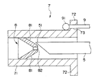
図7は、本発明の留置針組立体の針先被包部材による他の針先の被包状態を示す縦断面図である。
【0060】
本実施例において、内針ハブ6と針先被包部材7との間には連結部材9とは別に弾性体で構成された線状体10が設けられている。
【0061】
この線状体10は、図7に示すように内針5の針先51が針止部材8を抜脱した状態にあるとき伸張状態となり、その復元力により針先被包部材7に対し基端側への引張力を付与するものである。この線状体10により、針先51が針止部材8に係止するとともに、前述した連結部材9と相まって、針先51の基端側への抜け出しをより有効に防止し、針先被包部材7による針先51の保持・被包をさらに確実にすることができる。
【0062】
この線状体10としては、例えばゴム紐等を用いることができる。また、線状体10の内針ハブ6および針先被包部材7への固着は、前述の連結部材9と同様に行うことができ、針先被包部材7への固着は玉止め101を設けて固着することができる。
【0063】
次に、本発明の留置針組立体の使用方法(作用)の一例について図を参照しながら説明する。
【0064】
[1] 予め外針2と内針5とを組み立てておく。すなわち、図1に示すように、内針5を外針ハブ3の収容部31から挿入し、針先被包部材7、針止部材8、次いで外針2の内腔に挿通させ、内針ハブ6の先端が外針ハブ3の収容部31に係止するまで挿入する。このとき、針先51は外針2の先端面から突出している。
【0065】
また、連結部材9は収容部31に収容されており、内針ハブ6と針先被包部材7間を遊架している。
【0066】
[2] 次に、一体化された内針5および外針2を血管(静脈または動脈)に穿刺する。
【0067】
内針5の針先51が血管を確保すると、血管の内圧(血圧)により血液が内針5の内腔を経て内針ハブ6の内腔63に流入する。この血液のフラッシュバックは、視認性を有する内針ハブ6によって視ることができ、これにより、外針2の先端が血管を確保したことを確認することができる。
【0068】
[3] 外針2の先端が血管を確保したら、一方の手で外針2および外針ハブ3を移動しないように固定し、もう一方の手で内針ハブ6を把持して基端方向へ引き内針5を抜き出す。このとき、連結部材9の一端も内針ハブ6とともに基端側へ移動する。
【0069】
このとき内針5の針先51は、外針2を通過し、次いで針先被包部材7の管体71内を通過していく。
【0070】
[4] 針先51が針止部材8(8a )を抜けたとき、連結部材9は緊張状態となる。さらに、内針ハブ6を基端側へ移動させると、連結部材9は針先被包部材7を基端側へ引っ張る。一定以上の引張力が加わると、針先被包部材7は収容部31から離脱し、連結部材9を介して内針ハブ6と基端側へ共動する。
【0071】
[5] 次いで、針先被包部材7は、針先51を被包した状態で外針ハブ3から抜脱される。このとき、図6に示すように、針先51は針先被包部材7内に保持されている。針先51の先端側にある針止部材8(8a )により、該針先51は針先被包部材7の先端側へ突出することがなく、また、緊張した連結部材9により、基端側へ抜け出ることもないため、安全に廃棄等の処理に供することができる。
【0072】
[6] 一方、このようにして内針5が抜き取られると、血液が外針2内を基端側へ流れて収容部31に流入し、外針2の先端部21が血管を確保していることがわかる。この後、外針ハブ3には輸液ライン等が接続され、常法に従って輸液が行われる。
【0073】
以上、本発明の留置針組立体を図示の各実施例について説明したが、本発明は、これらに限定されるものではなく、留置針組立体を構成する各部材、特に針先被包部材7や連結部材9の構成は、同様の機能を発揮し得る任意の構成のものと置換することができる。
【0074】
例えば、外針ハブ3に基端開口部を封止するための栓体や外針2を皮膚に固定するための翼等が設けられていてもよい。
【0075】
また、連結部材9の各端部の連結位置、連結方法、連結構造も図示のものに限定されない。
【0076】
【発明の効果】
以上述べたように、本発明の留置針組立体によれば、使用済の内針の針先を簡単な操作で、かつ確実に被包することができるため、内針の廃棄等の処理を安全・円滑に行うことができる。
【0077】
また、内針自体に加工を施すものではないため、内針の強度低下等による不都合がなく、針先の被包を確実に行うことができる。
さらに、医療行為自体に何ら支障を及ぼさず、製造も容易である。
【図面の簡単な説明】
【図1】本発明の留置針組立体の実施例を示す縦断面図である。
【図2】図1に示す留置針組立体の針止部材の斜視図である。
【図3】図1に示す留置針組立体の針先被包部材を示す縦断面図である。
【図4】本発明の留置針組立体の他の実施例における針先被包部材の構成を示す縦断面図である。
【図5】本発明の留置針組立体のさらに他の実施例における針先被包部材の構成を示す縦断面図である。
【図6】本発明の留置針組立体の針先被包部材による針先の被包状態を示す縦断面図である。
【図7】本発明の留置針組立体の針先被包部材による針先の他の被包状態を示す縦断面図である。
【符号の説明】
1 留置針組立体
2 外針
21 先端部
3 外針ハブ
31 収容部
32 外針固定部
4 かしめ部材
5 内針
51 針先
6 内針ハブ
61 接着剤
62 孔
63 内腔
7 針先被包部材
71 管体
72 支持部
73 孔
8、8a、8b、8c 針止部材
81 テーパ部
82 孔
9 連結部材
91 玉止め
10 弾性体で構成された線状体
101 玉止め[0001]
[Technical field to which the invention belongs]
The present invention relates to an indwelling needle assembly, and more particularly to an indwelling needle assembly used, for example, during infusion.
[0002]
[Prior art]
When using an indwelling needle used for infusion, etc., the inner needle was housed in the outer needle (inner / outer needle integrated state), and these were punctured into the blood vessel, and then the outer needle was inserted to a predetermined position. The rear inner needle is withdrawn, and an infusion line is connected to the proximal end following the outer needle to circulate the drug solution and the like. As such an indwelling needle, what was described in Unexamined-Japanese-Patent No. 57-75660 is known.
[0003]
Here, the used inner needle that has been extracted is discarded, but an operator, a patient, a disposal worker, or the like may touch the sharp needle tip and be damaged. Used needles are contaminated with the patient's blood and body fluids, etc., and there is a risk of infection from hepatic wounds with hepatitis and various infectious diseases. .
[0004]
In order to solve such a problem, Japanese Patent Application Laid-Open No. 2-99070 discloses a venous catheter provided with a needle protection part for protecting the needle tip of the inner needle. In this needle protection component, a lock flange is engaged with an engagement slot provided in the inner needle so as to cover the needle tip of the inner needle.
[0005]
However, when the engagement slot is provided in the inner needle in this way, the strength of the inner needle is reduced at the slot portion, and therefore the inner needle is easily bent or broken at the slot portion during puncture or disposal, which is difficult to use. Yes, and if it breaks, it is difficult and very dangerous to retrieve the needle.
[0006]
In addition, the engagement slot is engraved on the outer wall surface of the inner needle. However, since the puncture needle such as the inner needle is usually made of a hard material such as stainless steel, it is difficult to process such a slot. is there. Furthermore, the depth of the engagement slot needs to be smaller than the thickness of the inner needle, but it cannot be said that the lock engagement between the needle and the flange is reliable in the slot having such a depth. . Particularly, since the lock flange is made of an elastic material such as rubber, even if the convex portion of the lock flange is once engaged with the engagement slot, the convex portion is elastically deformed and easily disengaged. It may end up. Therefore, it was insufficient and incomplete as a protective part for the needle tip.
[0007]
[Problems to be solved by the invention]
An object of the present invention is to provide an indwelling needle assembly that can encapsulate the needle tip of an inner needle easily and reliably, has no hindrance to puncture or disposal, and has high safety.
[0008]
[Means for Solving the Problems]
Such an object is achieved by the present inventions (1) to (4) below.
[0009]
(1) outer needle hub,
A hollow outer needle fixed to the outer needle hub;
An inner needle hub that can be locked to the outer needle hub;
An inner needle fixed to the inner needle hub and insertable into a lumen of the outer needle;
A needle tip encapsulating member that is removably fitted into the outer needle hub and can encapsulate the needle tip of the inner needle;
A connecting member that connects the inner needle hub and the needle tip encapsulation member, and transmits a tensile force applied when the inner needle hub is moved to the proximal end side with respect to the outer needle hub to the needle tip encapsulation member. An indwelling needle assembly having
The probe tip encapsulation member, the inner needle has a lumen that can be inserted, and provided with two stapling members return can be prevented to the needle tip on the distal end side of the inner needle to the lumen And
Each needle stop member is made of an elastic material and has a hole through which the inner needle can be inserted , and the diameter of the hole on the proximal end side is smaller than the outer diameter of the inner needle,
When the inner needle hub is moved proximally with respect to the outer needle hub and the needle tip of the inner needle is held between the two needle stop members, the needle tip encapsulating member is pulled by the tensile force of the connecting member. Is configured to detach from the outer needle hub .
[0010]
(2) Each said needle stop member is an indwelling needle assembly as described in said (1) which has the taper part which an outer diameter reduces gradually toward the base end side from the front end side.
[0011]
(3) The indwelling device according to (1) or (2) , wherein the connecting member is formed of a linear body that is in a tension state when the needle tip of the inner needle is encapsulated by the needle tip encapsulating member. Needle assembly.
[0012]
(4) Any of the above (1) to (3) , wherein the frictional force when the inner needle slides with respect to the needle stop member is smaller than the fitting force between the outer needle hub and the needle tip encapsulation member. The indwelling needle assembly according to claim 1.
[0019]
DETAILED DESCRIPTION OF THE INVENTION
Hereinafter, the indwelling needle assembly of the present invention will be described in detail based on a preferred embodiment shown in the accompanying drawings. 1 to 6, the right side of the drawing is referred to as “base end”, and the left side is referred to as “tip”.
[0020]
FIG. 1 is a longitudinal sectional view showing an embodiment of the indwelling needle assembly of the present invention, FIG. 2 is a perspective view of a needle stop member of the indwelling needle assembly shown in FIG. 1, and FIG. 3 is an indwelling needle assembly shown in FIG. FIG. 6 is a longitudinal sectional view showing a state in which the needle tip is encapsulated by the needle tip encapsulation member of the indwelling needle assembly of the present invention.
[0021]
The indwelling needle assembly 1 of the present invention includes an
[0022]
Hereinafter, each of these components will be described sequentially.
The
[0023]
Examples of the constituent material of the
[0024]
The outer needle 2 is caulked and fixed to the outer
[0025]
The outer needle 2 is constituted by a hollow tube, and as shown in FIG. 1, the
[0026]
Although it does not specifically limit as a constituent material of the outer needle 2, For example, soft resins, such as ethylene-tetrafluoroethylene copolymer (ETFE), a polyurethane, polyether nylon resin, are preferable. In this case, in order to ensure the internal visibility, the outer needle 2 can be entirely or partially made of a transparent or translucent material. In addition, an X-ray contrast agent such as barium sulfate can be blended in the constituent material of the outer needle 2 to provide a contrast function.
[0027]
As shown in FIG. 1, the
[0028]
As the material for the
[0029]
The
[0030]
As a constituent material of the
[0031]
A needle
The needle
[0032]
A method for fixing the needle
[0033]
The constituent material of the needle
[0034]
Further, in the
[0035]
The
[0036]
The diameter of the
[0037]
The friction force when the
[0038]
The material of the
[0039]
Examples of such elastic materials include, but are not limited to, natural rubber, isoprene rubber, butadiene rubber, styrene-butadiene rubber, nitrile rubber, chloroprene rubber, butyl rubber, acrylic rubber, ethylene-propylene rubber, hydrin rubber, urethane rubber, Various rubber materials (especially those vulcanized) such as silicone rubber and fluoro rubber, styrene, polyolefin, polyvinyl chloride, polyurethane, polyester, polyamide, polybutadiene, trans polyisoprene, fluorine Various thermoplastic elastomers such as rubber-based and chlorinated polyethylene are listed.
[0040]
The
[0041]
Moreover, the same material as the above-mentioned needle
[0042]
The connecting
[0043]
The connecting
[0044]
That is, when the
[0045]
When the
[0046]
As shown in FIG. 6, the extracted
[0047]
One end of the connecting
[0048]
As shown in FIGS. 1 and 6, the other end of the connecting
[0049]
The form / shape of the connecting
[0050]
The material of the connecting
[0051]
When the indwelling needle is assembled, the connecting
[0052]
FIG. 4 is a longitudinal sectional view showing another embodiment of the indwelling needle assembly of the present invention.
In the present embodiment, as shown in the drawing, the needle
[0053]
In the present embodiment, two
[0054]
In this embodiment, the connecting
[0055]
FIG. 5 is a longitudinal sectional view showing still another embodiment of the indwelling needle assembly of the present invention. In the present embodiment, as shown in the figure, the
[0056]
Such a sealing
[0057]
The cross-sectional shape of the
[0058]
In this embodiment, the connecting
[0059]
FIG. 7 is a longitudinal cross-sectional view showing a state where another needle tip is encapsulated by the needle tip encapsulation member of the indwelling needle assembly of the present invention.
[0060]
In this embodiment, a
[0061]
As shown in FIG. 7, the
[0062]
As this
[0063]
Next, an example of a method (action) of using the indwelling needle assembly of the present invention will be described with reference to the drawings.
[0064]
[1] The outer needle 2 and the
[0065]
Further, the connecting
[0066]
[2] Next, the integrated
[0067]
When the
[0068]
[3] When the distal end of the outer needle 2 secures the blood vessel, the outer needle 2 and the
[0069]
At this time, the
[0070]
[4] When the
[0071]
[5] Next, the needle
[0072]
[6] On the other hand, when the
[0073]
The indwelling needle assembly of the present invention has been described above with respect to the illustrated embodiments. However, the present invention is not limited to these embodiments, and each member constituting the indwelling needle assembly, particularly the needle
[0074]
For example, the
[0075]
Further, the connecting position, connecting method, and connecting structure of each end of the connecting
[0076]
【The invention's effect】
As described above, according to the indwelling needle assembly of the present invention, the needle tip of the used inner needle can be reliably encapsulated with a simple operation. Safe and smooth.
[0077]
Further, since the inner needle itself is not processed, there is no inconvenience due to a decrease in the strength of the inner needle, and the needle tip can be reliably encapsulated.
Furthermore, it does not interfere with the medical practice itself and is easy to manufacture.
[Brief description of the drawings]
FIG. 1 is a longitudinal sectional view showing an embodiment of an indwelling needle assembly according to the present invention.
2 is a perspective view of a needle stop member of the indwelling needle assembly shown in FIG. 1. FIG.
FIG. 3 is a longitudinal sectional view showing a needle tip encapsulation member of the indwelling needle assembly shown in FIG. 1;
FIG. 4 is a longitudinal sectional view showing a configuration of a needle tip encapsulation member in another embodiment of the indwelling needle assembly of the present invention.
FIG. 5 is a longitudinal sectional view showing a configuration of a needle tip encapsulating member in still another embodiment of the indwelling needle assembly of the present invention.
FIG. 6 is a longitudinal sectional view showing a state where the needle tip is encapsulated by the needle tip encapsulating member of the indwelling needle assembly of the present invention.
FIG. 7 is a longitudinal sectional view showing another enveloping state of the needle tip by the needle tip encapsulating member of the indwelling needle assembly of the present invention.
[Explanation of symbols]
DESCRIPTION OF SYMBOLS 1 Indwelling needle assembly 2
Claims (4)
前記外針ハブに固定された中空の外針と、
前記外針ハブに係止可能な内針ハブと、
前記内針ハブに固定され前記外針の内腔内に挿入可能な内針と、
前記外針ハブ内に離脱可能に嵌着され前記内針の針先を被包し得る針先被包部材と、
前記内針ハブと前記針先被包部材とを連結し、前記内針ハブを前記外針ハブに対し基端側へ移動させる際に加えられる引張力を針先被包部材に伝達する連結部材とを有する留置針組立体において、
前記針先被包部材は、前記内針が挿通可能な内腔を有し、かつその内腔内に前記内針の針先の先端側への戻りを防止し得る2つの針止部材を備えており、
前記各針止部材は、弾性材料で構成され、かつ前記内針を挿通可能な孔を有しており、その基端側の孔径は前記内針の外径よりも小さく、
前記内針ハブを前記外針ハブに対し基端側へ移動させ前記2つの針止部材の間に前記内針の針先を保持したとき、前記連結部材の引張力により前記針先被包部材が前記外針ハブから離脱するよう構成されていることを特徴とする留置針組立体。An outer needle hub,
A hollow outer needle fixed to the outer needle hub;
An inner needle hub that can be locked to the outer needle hub;
An inner needle fixed to the inner needle hub and insertable into a lumen of the outer needle;
A needle tip encapsulating member that is removably fitted into the outer needle hub and can encapsulate the needle tip of the inner needle;
A connecting member that connects the inner needle hub and the needle tip encapsulation member, and transmits a tensile force applied when the inner needle hub is moved to the proximal end side with respect to the outer needle hub to the needle tip encapsulation member. An indwelling needle assembly having
The probe tip encapsulation member, the inner needle has a lumen that can be inserted, and provided with two stapling members return can be prevented to the needle tip on the distal end side of the inner needle to the lumen And
Each needle stop member is made of an elastic material and has a hole through which the inner needle can be inserted , and the diameter of the hole on the proximal end side is smaller than the outer diameter of the inner needle,
When the inner needle hub is moved proximally with respect to the outer needle hub and the needle tip of the inner needle is held between the two needle stop members, the needle tip encapsulating member is pulled by the tensile force of the connecting member. Is configured to detach from the outer needle hub .
Priority Applications (1)
| Application Number | Priority Date | Filing Date | Title |
|---|---|---|---|
| JP09650497A JP3835882B2 (en) | 1997-03-31 | 1997-03-31 | Indwelling needle assembly |
Applications Claiming Priority (1)
| Application Number | Priority Date | Filing Date | Title |
|---|---|---|---|
| JP09650497A JP3835882B2 (en) | 1997-03-31 | 1997-03-31 | Indwelling needle assembly |
Publications (2)
| Publication Number | Publication Date |
|---|---|
| JPH10272182A JPH10272182A (en) | 1998-10-13 |
| JP3835882B2 true JP3835882B2 (en) | 2006-10-18 |
Family
ID=14166953
Family Applications (1)
| Application Number | Title | Priority Date | Filing Date |
|---|---|---|---|
| JP09650497A Expired - Fee Related JP3835882B2 (en) | 1997-03-31 | 1997-03-31 | Indwelling needle assembly |
Country Status (1)
| Country | Link |
|---|---|
| JP (1) | JP3835882B2 (en) |
Families Citing this family (12)
| Publication number | Priority date | Publication date | Assignee | Title |
|---|---|---|---|---|
| US6234999B1 (en) | 2000-01-18 | 2001-05-22 | Becton, Dickinson And Company | Compact needle shielding device |
| JP4633898B2 (en) * | 2000-08-21 | 2011-02-16 | テルモ株式会社 | Indwelling needle assembly |
| US6663592B2 (en) * | 2001-09-06 | 2003-12-16 | Medex, Inc. | Catheter introducer assembly having safety shielded needle |
| US8192404B2 (en) | 2005-10-25 | 2012-06-05 | Terumo Kabushiki Kaisha | Indwelling needle assembly |
| FR2900344B1 (en) * | 2006-04-26 | 2009-02-27 | Becton Dickinson France | INJECTION DEVICE WITH RETRACTABLE NEEDLE |
| JP4723419B2 (en) * | 2006-05-24 | 2011-07-13 | テルモ株式会社 | Indwelling needle assembly |
| JP5244794B2 (en) * | 2007-06-12 | 2013-07-24 | テルモ株式会社 | Method for manufacturing indwelling needle assembly |
| KR101132841B1 (en) | 2011-03-07 | 2012-04-02 | 김영재 | A suture |
| KR101185583B1 (en) | 2011-12-27 | 2012-09-24 | 김영재 | A suture which need not be knotted and a kit comprising the suture |
| US10178990B2 (en) | 2012-12-05 | 2019-01-15 | Y. Jacobs Medical Inc. | Apparatus for inserting surgical thread, and surgical procedure kit for inserting surgical thread comprising same |
| US10010317B2 (en) | 2012-12-05 | 2018-07-03 | Young Jae Kim | Method of improving elasticity of tissue of living body |
| WO2015083864A1 (en) | 2013-12-06 | 2015-06-11 | 주식회사 와이제이콥스메디칼 | Apparatus for inserting medical tube and surgical procedure kit for inserting medical tube, having same |
-
1997
- 1997-03-31 JP JP09650497A patent/JP3835882B2/en not_active Expired - Fee Related
Also Published As
| Publication number | Publication date |
|---|---|
| JPH10272182A (en) | 1998-10-13 |
Similar Documents
| Publication | Publication Date | Title |
|---|---|---|
| US7247148B2 (en) | Protector and storage needle assembly | |
| US8992483B2 (en) | Indwelling needle assembly and protector | |
| US7291130B2 (en) | Safety needle and catheter assembly | |
| US7740614B2 (en) | Indwelling needle assembly | |
| EP1131129B1 (en) | Blood seal having a spring-biased septum | |
| US7238169B2 (en) | Safety indwelling needle | |
| US8192404B2 (en) | Indwelling needle assembly | |
| JP4151311B2 (en) | Indwelling needle | |
| US20100280455A1 (en) | Needle-stent device | |
| JP3835882B2 (en) | Indwelling needle assembly | |
| US20030032922A1 (en) | Trapping of intravenous needle associated with a long catheter, and related methods | |
| JP4661240B2 (en) | Safety indwelling needle | |
| JP2005270638A5 (en) | ||
| CA2520353C (en) | Safety needle and catheter assembly | |
| JP2001190683A (en) | Needling tool | |
| JP4404571B2 (en) | Indwelling needle assembly | |
| JP3576765B2 (en) | Indwelling needle assembly | |
| WO2016152377A1 (en) | Catheter assembly | |
| JP4569124B2 (en) | Safety indwelling needle | |
| JP2005237638A5 (en) | ||
| JP4464540B2 (en) | Puncture tool | |
| JP2002011098A (en) | Needling instrument | |
| EP0752252A2 (en) | Needle tip protector | |
| WO2007049563A1 (en) | Indwelling needle assembly | |
| JP2004242763A (en) | Indwelling catheter |
Legal Events
| Date | Code | Title | Description |
|---|---|---|---|
| A131 | Notification of reasons for refusal |
Free format text: JAPANESE INTERMEDIATE CODE: A131 Effective date: 20050823 |
|
| A521 | Written amendment |
Free format text: JAPANESE INTERMEDIATE CODE: A523 Effective date: 20051003 |
|
| A131 | Notification of reasons for refusal |
Free format text: JAPANESE INTERMEDIATE CODE: A131 Effective date: 20051111 |
|
| A521 | Written amendment |
Free format text: JAPANESE INTERMEDIATE CODE: A523 Effective date: 20051205 |
|
| TRDD | Decision of grant or rejection written | ||
| A01 | Written decision to grant a patent or to grant a registration (utility model) |
Free format text: JAPANESE INTERMEDIATE CODE: A01 Effective date: 20060713 |
|
| A61 | First payment of annual fees (during grant procedure) |
Free format text: JAPANESE INTERMEDIATE CODE: A61 Effective date: 20060725 |
|
| R150 | Certificate of patent or registration of utility model |
Free format text: JAPANESE INTERMEDIATE CODE: R150 |
|
| FPAY | Renewal fee payment (event date is renewal date of database) |
Free format text: PAYMENT UNTIL: 20090804 Year of fee payment: 3 |
|
| FPAY | Renewal fee payment (event date is renewal date of database) |
Free format text: PAYMENT UNTIL: 20100804 Year of fee payment: 4 |
|
| FPAY | Renewal fee payment (event date is renewal date of database) |
Free format text: PAYMENT UNTIL: 20100804 Year of fee payment: 4 |
|
| FPAY | Renewal fee payment (event date is renewal date of database) |
Free format text: PAYMENT UNTIL: 20110804 Year of fee payment: 5 |
|
| FPAY | Renewal fee payment (event date is renewal date of database) |
Free format text: PAYMENT UNTIL: 20120804 Year of fee payment: 6 |
|
| FPAY | Renewal fee payment (event date is renewal date of database) |
Free format text: PAYMENT UNTIL: 20130804 Year of fee payment: 7 |
|
| LAPS | Cancellation because of no payment of annual fees |