JP4569124B2 - Safety indwelling needle - Google Patents
Safety indwelling needle Download PDFInfo
- Publication number
- JP4569124B2 JP4569124B2 JP2004051028A JP2004051028A JP4569124B2 JP 4569124 B2 JP4569124 B2 JP 4569124B2 JP 2004051028 A JP2004051028 A JP 2004051028A JP 2004051028 A JP2004051028 A JP 2004051028A JP 4569124 B2 JP4569124 B2 JP 4569124B2
- Authority
- JP
- Japan
- Prior art keywords
- needle
- protection member
- unit
- inner needle
- outer needle
- Prior art date
- Legal status (The legal status is an assumption and is not a legal conclusion. Google has not performed a legal analysis and makes no representation as to the accuracy of the status listed.)
- Expired - Fee Related
Links
Images


Description
本発明は、輸液、血液透析等に使用される留置針組立体に関する。さらに詳しくは、安全機構を備えた安全留置針に関する。 The present invention relates to an indwelling needle assembly used for infusion, hemodialysis and the like. More specifically, the present invention relates to a safety indwelling needle provided with a safety mechanism.
近年、医療従事者が血液で汚染された注射針等の鋭利な刃先によって、誤穿刺してしまうことによるエイズや肝炎ウィルス等への感染の危険性が問題となっている。そこで、内針と外針を含んでなる留置針組立体において、使用後の内針にキャップを再度かぶせることなくカバーして誤穿刺を防止する安全留置針が発明されている。例えば、穿刺後、留置針に備えられた釦を押すことによって、ばねによって内針が針カバー内部に引き込まれ収容されるという安全留置針が開示されている(例えば特許文献1)。
また、ばね式の針先保護手段が外針ハブの内部に配置され、内針を引き抜くことにより、外針ハブから針先保護手段が離脱し、それに内針の先端が覆われるという安全留置針が開示されている(例えば特許文献2)。
さらに、外針から内針を引き抜くときに、内針に備えられたスライド式のカバーが伸長し、針全体が収容されることを特徴とする安全留置針が開示されている(例えば特許文献3)。
In recent years, the risk of infection with AIDS, hepatitis virus, and the like due to erroneous puncture by a sharp blade such as an injection needle contaminated with blood has become a problem. Therefore, in the indwelling needle assembly including the inner needle and the outer needle, a safe indwelling needle that prevents erroneous puncture by covering the used inner needle without re-covering the cap has been invented. For example, a safety indwelling needle is disclosed in which, after puncturing, a button provided on the indwelling needle is pressed, and the inner needle is pulled into the needle cover and accommodated by a spring (for example, Patent Document 1) .
In addition, a safety indwelling needle is provided in which spring-type needle tip protection means is arranged inside the outer needle hub, and by pulling out the inner needle, the needle tip protection means is detached from the outer needle hub and the tip of the inner needle is covered therewith. Is disclosed (for example, Patent Document 2) .
Furthermore, a safety indwelling needle is disclosed in which when the inner needle is pulled out from the outer needle, a slide-type cover provided on the inner needle extends to accommodate the entire needle (for example, Patent Document 3). ).
従来の安全機構を備えた安全留置針においては、外針ユニットから引き抜いた内針をカバーする針先保護手段が、内針全体を収容する大きさを持つ必要があるために、留置針そのものの大きさが大きくなっていた。また、針先保護手段にばねを用いたものでは、そのばねの付勢力による内針の引き抜き抵抗が内針と針先保護手段の摩擦により高くなるために、内針引き抜き時に必要な力が増大し、使用感が悪化したりする問題があった。さらに、内針を針保護部材等で保護しても、針先が針先保護手段から再突出する危険性があり、また、針先保護手段の開口部のシールドも不完全なものであった。 In a safety indwelling needle equipped with a conventional safety mechanism, the needle tip protecting means that covers the inner needle pulled out from the outer needle unit needs to be large enough to accommodate the entire inner needle. The size was getting bigger. Further, the one using a spring needlepoint protecting means, necessary for the inner needle pullout resistance of that by the biasing force of the spring is increased by the friction of the inner needle and the needlepoint protecting means, when the inner needle retraction force There was a problem that the feeling of use deteriorated. Furthermore, even if the inner needle is protected by a needle protection member or the like, there is a risk that the needle tip may re-project from the needle tip protection means, and the shield at the opening of the needle tip protection means is incomplete. .
そこで、本発明は、如上の事情に鑑みてなされたもので、輸液や血液透析等に用いられる留置針において、誤穿刺対策の施された、コンパクトで使用感の良い、構造が簡単な安全留置針を提供することを目的とする。 Therefore, the present invention has been made in view of the above circumstances, and indwelling needles used for infusion, hemodialysis, etc., are provided with a safe, compact and easy-to-use structure with a countermeasure against erroneous puncture. The aim is to provide a needle.
即ち本発明は、
(1)内針と針保護部材を含む内針ユニットと、外針を含む外針ユニットからなる留置針であって、内針ユニットを相対的に外針ユニットから引き抜いた状態で、針保護部材は伸長して内針先端から所定長をカバーすることを特徴とする安全留置針及び、
(2)針保護部材が、複数の中空体のハウジングの組み合わせであることを特徴とする上記(1)記載の安全留置針及び、
(3)内針ユニットを相対的に外針ユニットから引くことによって、針保護部材が伸長されるための不規則部分を内針上に備えることを特徴とする上記(1)もしくは(2)記載の安全留置針及び、
(4)針保護部材に、上記不規則部分を備えた内針の針保護部材に対する相対的な動作を制御するフック部材を備えたことを特徴とする上記(1)〜(3)のいずれかに記載の安全留置針及び、
(5)内針ユニットと外針ユニットが組み立てられた使用前の安全留置針において、前記不規則部分が外針より近位側に位置することを特徴とする上記(1)〜(4)のいずれかに記載の安全留置針及び、
(6)針保護部材に、伸長を制限する第一ストッパーを備えたことを特徴とする上記(1)〜(5)のいずれかに記載の安全留置針及び、
(7)針保護部材に、針保護部材を伸長させた後に再度縮小することを阻止する第二ストッパーを備えていることを特徴とする上記(1)〜(6)のいずれかに記載の安全留置針及び、
(8)外針ユニットは、内針が挿通される内腔を有する外針と外針ハブ及び外針コネクター及び外針ハブと外針コネクターを連結するチューブ及び外針キャップからなることを特徴とする上記(1)〜(7)のいずれかに記載の安全留置針及び、
(9)外針ユニットは、内針が挿通される内腔を有する外針と他の医療用具と接続される接続手段を備えた外針ハブからなることを特徴とする上記(1)〜(7)のいずれかに記載の安全留置針に関する。
That is, the present invention
(1) An indwelling needle comprising an inner needle unit including an inner needle and a needle protection member and an outer needle unit including an outer needle, and the needle protection member in a state in which the inner needle unit is relatively pulled out from the outer needle unit. Is a safety indwelling needle that extends to cover a predetermined length from the tip of the inner needle, and
(2) The safety indwelling needle according to (1) above, wherein the needle protection member is a combination of a plurality of hollow housings;
(3) The above (1) or (2), wherein the inner needle unit is provided with an irregular portion on the inner needle for the needle protection member to be extended by pulling the inner needle unit relatively from the outer needle unit. Safety indwelling needles and
(4) Any of the above (1) to (3), wherein the needle protection member is provided with a hook member for controlling a relative operation of the inner needle having the irregular portion with respect to the needle protection member. Safety indwelling needle as described in
(5) In the safety indwelling needle before use in which the inner needle unit and the outer needle unit are assembled, the irregular portion is located proximal to the outer needle. The safety indwelling needle according to any one of the above ,
(6) The safety indwelling needle according to any one of (1) to (5) above, wherein the needle protection member is provided with a first stopper for restricting extension;
(7) The safety according to any one of (1) to (6) above, wherein the needle protection member includes a second stopper that prevents the needle protection member from being contracted again after being extended. Indwelling needle and
(8) The outer needle unit includes an outer needle having a lumen through which the inner needle is inserted, an outer needle hub, an outer needle connector, a tube connecting the outer needle hub and the outer needle connector, and an outer needle cap. The safety indwelling needle according to any one of (1) to (7) above and
(9) The outer needle unit includes an outer needle hub having an outer needle having a lumen through which the inner needle is inserted and a connecting means connected to another medical device. It relates to the safety indwelling needle in any one of 7).
本発明による安全留置針は内針ユニットを引き抜くことによって内針の先端を含む所定長を針保護部材内部に格納するものである。針保護部材を伸長式とすることでコンパクトな安全留置針が得られ、内針格納後にハウジング部材の短縮を防ぐことにより、内針先端の針カバー部材からの突出の可能性を排除するものである。 The safety indwelling needle according to the present invention stores a predetermined length including the tip of the inner needle inside the needle protection member by pulling out the inner needle unit. By making the needle protection member extendable, a compact safety indwelling needle can be obtained, and by eliminating the shortening of the housing member after storing the inner needle, it eliminates the possibility of protrusion of the inner needle tip from the needle cover member is there.
以下に、本発明による安全留置針を図面に示す好適な実施例に基づいて詳細に説明する。実施例の説明にあたっては、留置針操作時における医療従事者側を近位側、患者側を遠位側と表現する。また、特に構成部材の端部を説明するにあたっては、医療従事者側を近位端、患者側を遠位端と表現する。 Below, the safety indwelling needle by this invention is demonstrated in detail based on the suitable Example shown on drawing. In the description of the embodiments, the medical staff side at the time of indwelling needle operation is expressed as the proximal side, and the patient side is expressed as the distal side. In particular, when describing the end portions of the constituent members, the medical staff side is expressed as a proximal end, and the patient side is expressed as a distal end.
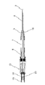
図1は外針から内針を引き抜く前の本発明による安全留置針の一実施例を示す断面図である。図2は図1の実施例における外針から内針が引き抜かれ、内針がカバーされた状態を示す断面図である。
実施例1における安全留置針は、特に人工透析等の血液浄化療法に適する留置針として使用される。
FIG. 1 is a sectional view showing an embodiment of the safety indwelling needle according to the present invention before the inner needle is pulled out from the outer needle. FIG. 2 is a cross-sectional view showing a state where the inner needle is pulled out from the outer needle in the embodiment of FIG. 1 and the inner needle is covered .
The safety indwelling needle in Example 1 is used as an indwelling needle particularly suitable for blood purification therapy such as artificial dialysis.
図1及び図2で示す安全留置針は、内針ユニット1と外針ユニット2より構成される。内針ユニット1は遠位端に鋭利な針先3および近位端に内針ハブ14を備える内針8、さらに内針ハブ14に装着された内針キャップ15を備える。そして、本実施例においては、中空体の組み合わせでスライド式に伸長する第一ハウジング部材28、第二ハウジング部材29、第三ハウジング部材30からなる針保護部材13を備えている。
外針ユニット2は、内腔16を備える外針4と外針ハブ5及び外針コネクター6、及び外針ハブ5と外針コネクター6を接続する可撓性を備えたチューブ7及び外針キャップ9を備える。
The safety indwelling needle shown in FIGS. 1 and 2 includes an inner needle unit 1 and an outer needle unit 2. The inner needle unit 1 includes an
The outer needle unit 2 includes an outer needle 4 having an
外針ユニット2の外針4は中空状をなし、適度な可撓性を有するものが好ましく用いられる。外針4の材質としては、例えばエチレン−テトラフルオロエチレン共重合体(ETFE)、ポリウレタン、ポリエーテルナイロン樹脂、ポリプロピレン等の各種軟質樹脂が好ましい。外針4は、その全部または一部が内部の視認性を有していてもよい。また、外針4の材料中に、例えば硫酸バリウム、炭酸バリウム等のX線造影剤を配合し、造影機能を持たせることもできる。 The outer needle 4 of the outer needle unit 2 is preferably hollow and has a suitable flexibility. As a material of the outer needle 4, for example, various soft resins such as ethylene-tetrafluoroethylene copolymer (ETFE), polyurethane, polyether nylon resin, and polypropylene are preferable. All or part of the outer needle 4 may have internal visibility. Further, an X-ray contrast agent such as barium sulfate or barium carbonate may be blended in the material of the outer needle 4 to provide a contrast function.
外針4の遠位端付近においては、生体への穿刺を容易且つ低侵襲で行うために、外径が遠位端方向に向かって漸減するテーパ状をなしていることが好ましい。また、外針4の遠位端付近に、内部を流れる液体の出入りを効率よく行うために、1個若しくは複数の穴19を設けていても良い。そして、外針4の近位端には外針ハブ5が液密に固着され、外針4の内腔16と外針ハブ5の内部とが連通している。そして、外針ハブ5にはチューブ7が接続され、さらに内部に他の医療用具と接続されるメスルアーテーパ17を有する外針コネクター6を備えている。外針コネクター6の近位端付近外周上に、他の医療用具との接続を確実にするため、ロック手段20を有してもよい。また、この外針コネクター6を備えず、チューブ7の可撓性を利用して他の医療用具と接続することも可能である。
In the vicinity of the distal end of the outer needle 4, it is preferable that the outer diameter of the outer needle 4 is tapered so as to gradually decrease toward the distal end in order to puncture the living body easily and with minimal invasiveness. In addition, one or a plurality of
外針コネクター6には外針キャップ9が冠着されている。また、外針キャップ9の内部には内針8が貫通することが出来る弾性を備えたパッキン10を備えている。このパッキン10によって内針8を引き抜いたあとの貫通穴が塞がれ、外針ユニット2の近位端から液体が流出するのを防ぐことが出来る。
また、外針キャップ9には、後述する内針ユニット1に備えられた、内針8の針先3を格納しカバーする針保護部材13の第三ハウジング部材30が取り外し可能な状態で連結される。第三ハウジング部材30との連結方法は特に限定されないが、内針ユニット1を外針ユニット2から引き抜く工程においては、針保護部材13の遠位端が外針キャップ9に連結され、後述する内針8上の不規則部分により針保護部材13が伸長し、針保護部材13の各ハウジング部材(28,29)に備えられた伸び方向を制御する第一ストッパー25により、それ以上針保護部材13が伸びない状態まで達したときに、それ以上内針ユニット1を引くことによって針保護部材13が外針キャップ9から離脱する状態で取り付けられていることが好ましい。例えば外針キャップ9及び第三ハウジング部材30に可撓性を備えた鍵状部材21と鍵状部材21が引っかかる突条部22を有し、それらの組み合わせによって取り外し可能に固定する手段を備えることで得ることが出来る。鍵状部材21と突条部22は、それらの組み合わせであれば外針キャップ9及び第三ハウジング部材30のどちらに備えてあっても良い。
An
A
内針8は、中空針であり、その材質として、例えば、ステンレス鋼やアルミニウムまたはアルミニウム合金、チタンまたはチタン合金が挙げられるが、易加工性やコスト等からステンレス鋼を用いることが好ましい。また、内針8の遠位端には鋭利な針先3が形成されている。この針先3の形状は特に限定されるものではないが、本実施例においては内針8の軸線に対して、所定角度傾斜した刃面を有するものとした。
The
また、図2に示すように、内針8の表面上の一部には、針保護部材13の伸長動作の開始及び内針ユニット1からの脱落防止、さらには後述するフック部材11による内針8の制止を目的とした不規則部分が備えられている。その不規則部分とは、例えば内針8の円周表面上に突出部18を設ければよい。この突出部18は円周を全てにわたるドーナツ状の突出でも良いし、円周の一部でも良い。円周の一部である場合、円周上に複数の突出部を形成していてもよい。また、この突出部18を設ける位置については、図2に示すように、内針ユニット1を外針ユニット2から相対的に引き抜くときに、突出部18が針保護部材13の内部空間の近位側まで到達し、それ以上引き抜くことで、針保護部材13が伸長を始め、針保護部材13が伸びきった状態において、内針8の針先3が針保護部材13内部に完全に格納される位置である必要がある。
Further, as shown in FIG. 2, a part on the surface of the
さらに、本発明においては、伸長する針保護部材13において、内針8の先端部分の所定長のみをカバーするために、前述の突出部18を内針8の中ほどの位置、すなわち、内針ユニット1と外針ユニット2が組み立てられた穿刺時の状態において、外針ユニット2の内部空間に位置するように設けることが可能となる。これによって、不規則部分が外針4の内腔16に位置せず、外針4の表面に影響を与えないので、患者への穿刺に際して内針8のこの突出部18が何ら不都合を与えることが無い。したがって、大きめの突出部18を設けることが可能となり、針保護部材13の内針ユニット1からの脱落及びフック部材11による制止を確実に行うことが容易になる。
さらには、突出部18を外針ユニット2の内部ではなく内針8の近位側に設けてもよい。例えば、内針ユニット1及び外針ユニット2が組み立てられた使用前の状態で、針保護部材13内部に突出部18が納まるような位置に設けてもよい。
Furthermore, in the present invention, in order to cover only the predetermined length of the tip portion of the
Furthermore, the
内針ユニット1は、外針ユニット2の内腔に挿入され、内針8が内部を貫通する針保護部材13は内針ハブ14の遠位端と外針キャップ9の近位端の間に挟まれ、外針キャップ9の近位端に取り外し可能な状態で連結される。内針8の近位端は内針ハブ14の遠位端において液密に固着され、内針8の内腔は内針ハブ14の内部空間と連通している。内針ハブ14は、略円筒状の中空部材で構成されている。内針8と内針ハブ14との固定方法は、例えば、嵌合、カシメ、融着、接着剤による接着等が挙げられる。また、これらを併用して固定しても良い。さらに、この内針ハブ14は好ましくは透明、着色透明又は半透明の樹脂で構成され、内針ハブ14内部が視認可能であることが好ましい。これにより血液のフラッシュバックの確認が可能となる。
The inner needle unit 1 is inserted into the lumen of the outer needle unit 2, and the
また、内針ハブ14の近位端には通気フィルタ23が設置されていることが好ましい。若しくは、図1に示すように、通気フィルタ23を備えた内針キャップ15を内針ハブ14の近位端に取り付けてもよい。この通気フィルタ23は気体は透過するが、液体は遮断する性質を持ち合わせるものである。例えば、各種焼結多孔体や疎水性不織布、その他の多孔質体が挙げられる。焼結多孔体としては例えばポリエチレン等の粉末の高分子材料と、親水性や水溶性、水膨潤性ポリマーとを含む材料を焼結したものが好ましい。この様な焼結多孔体を通気フィルタ23に用いることによって、血液等の液体との接触によって通気も遮断されるので、外部からの空気の進入を防ぐことが出来る。
In addition, a
次に図1及び図2を参照しながら、本発明による針保護部材13について詳細に説明する。
図2に示すように、本実施例による針保護部材13は、径の異なる略円筒状の中空体の組み合わせ(第一〜第三ハウジング部材(28〜30))によって構成され、スライド式に伸長することが出来る。針保護部材13の遠位端と近位端には内針8が貫通する開口部を有している。この開口部は遠位端においてはその形は特に限定されないが、近位側の開口部においては、前述した突出部18が通り抜けない大きさである必要があり、略円形状であることが好ましい。また、針保護部材13内部に、内針8が貫通され、内針8の外径と略等しく、突出部18が通ることの出来ない内径の金属等からなる硬質のOリング(図示しない。)を備えることにより、さらに確実に針保護部材13から内針8が抜けるのを防止することが出来る。このOリングは針保護部材13の内部近位側に固定されていることが好ましい。
Next, the
As shown in FIG. 2, the
図2のとおり、内針ユニット1が外針ユニット2から相対的に引き抜かれることによって、針保護部材13の近位側開口部内面に前述の突出部18が接触し、それ以上引き抜くことによってスライド式の針保護部材13が伸長を開始する。このとき、針保護部材13の近位端内面に接触する位置まで移動した突出部18を備えた内針8は、針保護部材13の近位端側に設けられたフック部材11によって、針保護部材13に対して相対的な移動が出来ないように制止される。そして、さらに内針ユニット1を引き抜くことによって、針保護部材13は伸長し、針保護部材13を構成する中空体に備えられた第一ストッパー25によってそれ以上伸びない状態になったときに、中空体に備えられた第二ストッパー26によって針保護部材13は短縮できない様に制御される。そして、内針8の突出部18より遠位側の針先3を含む部分は、伸長した針保護部材13によりカバーされる。
As shown in FIG. 2, the inner needle unit 1 is pulled out relatively from the outer needle unit 2, so that the
針保護部材13が伸びきった状態から、さらに内針ユニット1を引くことにより、針保護部材13の遠位端と外針キャップ9の連結は解け、図2に示すように内針ユニット1と外針ユニット2は分離される。また、針保護部材13を構成するハウジング部材に、針保護部材13を縮めた状態ではその状態を維持し、ある程度の力でハウジング部材を引くことでその状態が解除されるようなストッパー(図示しない。)を有してもよい。
図2では針保護部材13を3種類の径が異なる中空体のハウジング部材(28〜30)の組み合わせとしたが、針保護部材13を構成するハウジング部材の数については特に限定しない。組み合わせるハウジング部材の数量を増加することによって、縮めた状態の針保護部材13の軸線方向の長さを短くすることが可能となるが、あまり多すぎると、構造が複雑になり、また、針保護部材13の径が大きくなりすぎるので好ましくなく、また、ハウジング部材の数量を減少させると、針保護部材13の構造は単純となるが、針保護部材13を縮めた状態での全長を短くすることが出来ず、その結果、安全留置針の全長が長くなり好ましくない。また、図2では遠位端方向側に直径の大なる中空体を図示しているが、限定せず、例えば遠位端方向側に向かって直径が小さくなる中空体を使用しても良い(図示しない。)。
By further pulling the inner needle unit 1 from the state in which the
In FIG. 2, the
次に本実施例における安全留置針使用時の工程を説明する。図1に示す安全留置針を体内に穿刺後、図2の状態になるように相対的に内針ユニット1を外針ユニット2から引き抜く。このとき、針保護部材13の遠位端は外針ユニット2側の外針キャップ9に連結されているために、針保護部材13は外針ユニット2側に連結した状態のままである。そして、内針8上に備えられた突出部18が針保護部材13の近位端の内面に到達し、そこからさらに内針ユニット1を引き抜くことによって、針保護部材13の伸長が開始される。 そして、針保護部材13が第一ストッパー25による限界まで伸長されると、さらにそれ以上内針ユニット1を引くことにより、針保護部材13の遠位端と外針キャップ9の連結が外れ、図2に示すように、内針ユニット1と外針ユニット2は分離される。
Next, the process at the time of using the safety indwelling needle in a present Example is demonstrated. After the safety indwelling needle shown in FIG. 1 is punctured into the body, the inner needle unit 1 is relatively pulled out from the outer needle unit 2 so that the state shown in FIG. At this time, since the distal end of the
分離した内針ユニット1の内針8は、その針先3を含む遠位端が伸長した針保護部材13によってカバーされており、安全に廃棄することが可能である。また、針保護部材13に備えられた第二ストッパー26によって、伸長した針保護部材13は再度短縮することが出来ず、さらに、針保護部材13内部のフック部材11による内針8上の突出部18の制止により、内針8が針保護部材13に対して相対的に移動出来ないので、内針8の針先3は再度針保護部材13から突出することが無く、より安全に確実に内針8をカバーすることが可能となる。
The separated
図3は外針から内針を引き抜く前の本発明による安全留置針の一実施例を示す断面図である。図4は図3の実施例における外針から内針が引き抜かれ、内針がカバーされた状態を示す断面図である。
実施例2における安全留置針は、主に輸液等に使用される留置針として使用される。
FIG. 3 is a sectional view showing an embodiment of the safety indwelling needle according to the present invention before the inner needle is pulled out from the outer needle. FIG. 4 is a cross-sectional view showing a state where the inner needle is pulled out from the outer needle in the embodiment of FIG. 3 and the inner needle is covered .
The safety indwelling needle in Example 2 is used as an indwelling needle mainly used for infusion.
図3及び図4で示す安全留置針は、内針ユニット31と外針ユニット32より構成される。内針ユニット31は遠位端に鋭利な針先33および近位端に内針ハブ44を備える内針38、さらに内針ハブ44に装着された内針キャップ45を備える。そして、本実施例においては、中空体の組み合わせでスライド式に伸長する第一ハウジング部材58、第二ハウジング部材59、第三ハウジング部材60からなる針保護部材43を備えている。
外針ユニット32は、内腔46を備える外針34と外針ハブ35を備える。
The safety indwelling needle shown in FIGS. 3 and 4 includes an
The
外針ユニット32の外針34は中空状をなし、適度な可撓性を有するものが好ましく用いられる。外針34の材質としては、例えばエチレン−テトラフルオロエチレン共重合体(ETFE)、ポリウレタン、ポリエーテルナイロン樹脂、ポリプロピレン等の各種軟質樹脂が好ましい。外針34は、その全部または一部が内部の視認性を有していてもよい。 また、外針34の材料中に、例えば硫酸バリウム、炭酸バリウム等のX線造影剤を配合し、造影機能を持たせることもできる。
The
外針34の遠位端付近においては、生体への穿刺を容易且つ低侵襲で行うために、外径が遠位端方向に向かって漸減するテーパ状をなしていることが好ましい。また、外針34の遠位端付近に、内部を流れる液体の出入りを効率よく行うために、1個若しくは複数の穴49を設けていても良い。そして、外針34の近位端には外針ハブ35が液密に固着され、外針34の内腔46と外針ハブ35の内部とが連通している。また、外針ハブ35の内面構造は、輸液セット、シリンジ等の医療用具と接続が可能となるように、メスルアーテーパ47を形成していることが好ましい。また、外針ハブ35の近位側の外周上に、他の医療用具との接続を確実にするため、ロック手段50を備えていてもよい。
In the vicinity of the distal end of the
また、外針ハブ35には、後述する内針ユニット31に備えられた、内針38の針先33を格納しカバーする第三ハウジング部材60が取り外し可能な状態で連結される。第三ハウジング部材60との連結方法は特に限定されないが、内針ユニット31を外針ユニット32から引き抜く工程においては、針保護部材43が外針ハブ35に連結され、後述する内針38上の不規則部分の作用により針保護部材43が伸長し、針保護部材43の各ハウジング部材(58,59)に備えられた伸び方向を制御する第一ストッパー55により、それ以上針保護部材43が伸びない状態まで達したときに、それ以上内針ユニット31を引くことによって針保護部材43が外針ハブ35から離脱する状態で取り付けられていることが好ましい。例えば外針ハブ35及び第三ハウジング部材60に可撓性を備えた鍵状部材51と鍵状部材51が引っかかる突条部(図示しない。)を有し、それらの組み合わせによって取り外し可能に固定する手段を備えることで得ることが出来る。鍵状部材51と突条部は、それらの組み合わせであれば外針ハブ35及び第三ハウジング部材60のどちらに備えてあっても良い。また、突条部として、外針ハブ35に備えられたロック手段を用いてもよい。本実施例においては、この突条部に外針ハブ35に備えられたロック手段50を用いた。
A
内針38は、中空針であり、その材質として、例えば、ステンレス鋼やアルミニウムまたはアルミニウム合金、チタンまたはチタン合金が挙げられるが、易加工性やコスト等からステンレス鋼を用いることが好ましい。また、内針38の遠位端には鋭利な針先33が形成されている。この針先33の形状は特に限定されるものではないが、本実施例においては内針38の軸線に対して、所定角度傾斜した刃面を有するものとした。
The
また、図4に示すように、内針38の表面上の一部には、針保護部材43の伸長動作の開始及び内針ユニット31からの脱落防止、さらには後述するフック部材41による内針38の制止を目的とした不規則部分が備えられている。その不規則部分とは、例えば内針38の円周表面上に突出部48を設ければよい。この突出部48は円周を全てにわたるドーナツ状の突出でも良いし、円周の一部でも良い。円周の一部である場合、円周上に複数の突出部を形成していてもよい。また、この突出部48を設ける位置については、図4に示すように、内針ユニット31を外針ユニット32から相対的に引き抜くときに、突出部48が針保護部材43の内部空間の近位側まで到達し、それ以上引き抜くことで、針保護部材43が伸長を始め、針保護部材43が伸びきった状態において、内針38の針先33が針保護部材43内部に完全に格納される位置である必要がある。
As shown in FIG. 4, a part of the surface of the
さらに、本発明においては、伸長する針保護部材43において、内針38の先端部分の所定長のみをカバーするために、前述の突出部48を内針38の中ほどの位置、すなわち、内針ユニット31と外針ユニット32が組み立てられた穿刺時の状態において、外針ユニット32の内部空間に位置するように設けることが可能となる。これによって、不規則部分が外針34の内腔46に位置せず、外針34の表面に影響を与えないので、患者への穿刺に際して内針38のこの突出部48が何ら不都合を与えることが無い。したがって、大きめの突出部48を設けることが可能となり、針保護部材43の内針ユニット31からの脱落及びフック部材41による制止を確実に行うことが容易になる。
さらには、突出部48を外針ユニット32の内部ではなく内針38の近位側に設けてもよい。例えば、内針ユニット31及び外針ユニット32が組み立てられた使用前の状態で、針保護部材43内部に突出部48が納まるような位置に設けてもよい。
Further, in the present invention, in order to cover only the predetermined length of the tip portion of the
Furthermore, the
内針ユニット31は、外針ユニット32の内腔に挿入され、内針38が内部を貫通する針保護部材43は内針ハブ44の遠位端と外針ハブ35の近位端の間に挟まれ、外針ハブ35の近位端に取り外し可能な状態で連結される。内針38の近位端は内針ハブ44の遠位端において液密に固着され、内針38の内腔は内針ハブ44の内部空間と連通している。内針ハブ44は、略円筒状の中空部材で構成されている。内針38と内針ハブ44との固定方法は、例えば、嵌合、カシメ、融着、接着剤による接着等が挙げられる。また、これらを併用して固定しても良い。さらに、この内針ハブ44は好ましくは透明、着色透明又は半透明の樹脂で構成され、内針ハブ44内部が視認可能であることが好ましい。これにより血液のフラッシュバックの確認が可能となる。
The
また、内針ハブ44の近位側には通気フィルタ53が設置されていることが好ましい。若しくは、図3に示すように、通気フィルタ53を備えた内針キャップ45を内針ハブ44の近位端に取り付けてもよい。この通気フィルタ53は気体は透過するが、液体は遮断する性質を持ち合わせるものである。例えば、各種焼結多孔体や疎水性不織布、その他の多孔質体が挙げられる。焼結多孔体としては例えばポリエチレン等の粉末の高分子材料と、親水性や水溶性、水膨潤性ポリマーとを含む材料を焼結したものが好ましい。この様な焼結多孔体を通気フィルタ53に用いることによって、血液等の液体との接触によって通気も遮断されるので、外部からの空気の進入を防ぐことが出来る。
Further, the proximal side of the inner needle hub 4 4 It is preferable that the
次に図3及び図4を参照しながら、本発明による針保護部材43について詳細に説明する。
図4に示すように、本実施例による針保護部材43は、径の異なる略円筒状の中空体の組み合わせ(第一〜第三ハウジング部材(58〜60))によって構成され、スライド式に伸長することが出来る。針保護部材43の遠位端と近位端には内針が貫通する開口部を有している。この開口部は遠位端においてはその形は特に限定されないが、近位端の開口部においては、前述した突出部48が通り抜けない大きさである必要があり、略円形状であることが好ましい。また、針保護部材43内部に、内針38が貫通され、内針38の外径と略等しく、突出部48が通ることの出来ない内径の金属等からなる硬質のOリング(図示しない。)を備えることにより、さらに確実に針保護部材43から内針38が抜けるのを防止することが出来る。このOリングは針保護部材43の内部近位側に固定されていることが好ましい。
Next, the
As shown in FIG. 4, the needle protecting member 4 3 according to this embodiment includes a combination of different substantially cylindrical hollow body diameters (the first to third housing members (58 to 60)), the sliding Can be extended. The distal and proximal ends of the needle protecting member 4 3 has an opening which the inner needle penetrates. The shape of the opening is not particularly limited at the distal end, but the opening at the proximal end needs to be large enough to prevent the
図4のとおり、内針ユニット31が外針ユニット32から相対的に引き抜かれることによって、針保護部材43の近位端開口部内面に前述の突出部48が接触し、それ以上引き抜くことによってスライド式の針保護部材43が伸長を開始する。このとき、針保護部材43の近位端内面に接触する位置まで移動した突出部48を備える内針38は、針保護部材43の近位側に設けられたフック部材41によって、針保護部材43に対して相対的な移動が出来ないように制止される。そして、さらに内針ユニット31を引き抜くことによって、針保護部材43は伸長し、針保護部材43を構成する中空体に備えられた第一ストッパー55によってそれ以上伸びない状態になったときに、中空体に備えられた第二ストッパー56によって針保護部材43は短縮できない様に制御される。そして、内針38の突出部48より遠位側の針先を含む部分は、伸長した針保護部材43によりカバーされる。
As shown in FIG. 4, when the
針保護部材43が伸びきった状態から、さらに内針ユニット31を引くことにより、針保護部材43の遠位端と外針ハブ35の連結は解け、図4に示すように内針ユニット31と外針ユニット32は分離される。また、針保護部材43を構成するハウジング部材に、針保護部材43を縮めた状態ではその状態を維持し、ある程度の力で針保護部材43を引くことでその状態が解除されるようなストッパー(図示しない。)を有してもよい。
図4では針保護部材43を3種類の径が異なる中空体のハウジング部材(58〜60)の組み合わせとしたが、針保護部材43を構成するハウジング部材の数については特に限定しない。組み合わせるハウジング部材の数量を増加することによって、縮めた状態の針保護部材43の軸線方向の長さを短くすることが可能となるが、あまり多すぎると、構造が複雑になり、また、針保護部材の径が大きくなりすぎるので好ましくなく、また、中空体の数量を減少させると、針保護部材43の構造は単純となるが、針保護部材43を縮めた状態での全長を短くすることが出来ず、安全留置針の全長が長くなり好ましくない。また、図4では遠位端方向側に直径の大なる中空体を図示しているが、限定せず、例えば遠位端方向側に向かって直径が小さくなる中空体を使用しても良い(図示しない。)。
By further pulling the
In FIG. 4, the
次に本実施例における安全留置針使用時の工程を説明する。図3に示す安全留置針を体内に穿刺後、図4の状態になるように相対的に内針ユニット31を外針ユニット32から引き抜く。このとき、針保護部材43の遠位端は外針ユニット32側の外針ハブ35に連結されているために、針保護部材43は外針ユニット32側に連結した状態のままである。そして、内針38上に備えられた突出部48が針保護部材43の近位端の内面に到達し、そこからさらに内針ユニット31を引き抜くことによって、針保護部材43の伸長が開始される。そして、針保護部材43が第一ストッパー55による限界まで伸長されると、さらにそれ以上内針ユニット31を引くことにより、針保護部材43の遠位端と外針ハブ35の連結が外れ、図4に示すように、内針ユニット31と外針ユニット32は分離される。
Next, the process at the time of using the safety indwelling needle in a present Example is demonstrated. After the safety indwelling needle shown in FIG. 3 is punctured into the body, the
分離した内針ユニット31の内針38は、その針先33を含む先端部分が伸長した針保護部材43によってカバーされており、安全に廃棄することが可能である。また、針保護部材43に備えられた第二ストッパー56によって、伸長した針保護部材43は再度短縮することが出来ず、さらに、針保護部材43内部のフック部材41による内針38上の突出部48の制止により、内針38が針保護部材43に対して相対的に移動出来ないので、内針38の針先33は再度針保護部材43から突出することが無く、より安全に確実に内針38をカバーすることが可能となる。
The
1,31 内針ユニット
2,32 外針ユニット
3,33 針先
4,34 外針
5,35 外針ハブ
6,36 外針コネクター
7,37 チューブ
8,38 内針
9 外針キャップ
10 パッキン
13,43 針保護部材
14,44 内針ハブ
15,45 内針キャップ
16,46 内腔(外針)
17,47 メスルアーテーパ
20,50 ロック手段
21,51 鍵状部材
22 突条部
23,53 通気フィルタ
25,55 第一ストッパー
26,56 第二ストッパー
28,58 第一ハウジング部材
29,59 第二ハウジング部材
30,60 第三ハウジング部材
1,31
17, 47
Claims (8)
突出部からなる不規則部分が前記内針上に設けられ、
複数の中空体のハウジングの組み合わせからなる前記針保護部材が、前記不規則部分が通り抜けない大きさの開口部と該不規則部分を備えた内針の該針保護部材に対する相対的な動作を制御するフック部材とを近位端側に備え、
前記内針ユニットを相対的に前記外針ユニットから引き抜くことにより、前記不規則部分が前記針保護部材の前記開口部の形成された近位端に接触すると共に、該近位端に接触した不規則部分を前記フック部材が制止し、
更に該内針ユニットを引き抜くことにより、該複数の中空体のハウジング同士が相対的にスライドして該針保護部材が伸長し、該内針の先端から該不規則部分の形成部位までの所定長をカバーすることを特徴とする安全留置針。 An indwelling needle comprising an inner needle unit including an inner needle , an inner needle hub and a needle protection member, and an outer needle unit including an outer needle and an outer needle hub ,
An irregular portion consisting of a protrusion is provided on the inner needle,
The needle protection member comprising a combination of a plurality of hollow body housings controls the relative operation of the inner needle having the irregular portion and the inner needle having the irregular portion with respect to the needle protection member. A hook member on the proximal end side,
By withdrawing the inner needle unit from a relatively the outer needle unit, with pre-Symbol erratically portion contacts the proximal end which is formed of the opening of the needle guard member, in contact with the proximal end The hook member stops the irregular part,
Further, by pulling out the inner needle unit, the housings of the plurality of hollow bodies slide relative to each other, the needle protection member extends, and a predetermined length from the tip of the inner needle to the site where the irregular portion is formed. A safety indwelling needle characterized by covering.
Priority Applications (10)
| Application Number | Priority Date | Filing Date | Title |
|---|---|---|---|
| JP2004051028A JP4569124B2 (en) | 2004-02-26 | 2004-02-26 | Safety indwelling needle |
| TW094105526A TWI308874B (en) | 2004-02-26 | 2005-02-24 | Safe indwelling needle |
| KR1020050015354A KR100893709B1 (en) | 2004-02-26 | 2005-02-24 | Safe retained needle |
| CNB2005100510522A CN100536944C (en) | 2004-02-26 | 2005-02-25 | Safety indwelling needle |
| EP05004231A EP1568392B1 (en) | 2004-02-26 | 2005-02-25 | Safety indwelling needle |
| AT05004231T ATE359845T1 (en) | 2004-02-26 | 2005-02-25 | SAFETY PERMANENT PIN |
| US11/065,579 US20050192536A1 (en) | 2004-02-26 | 2005-02-25 | Safety indwelling needle |
| DE602005000895T DE602005000895T2 (en) | 2004-02-26 | 2005-02-25 | Sicherheitsdauerverweilnadel |
| ES05004231T ES2281856T3 (en) | 2004-02-26 | 2005-02-25 | PERMANENT IMPLANTATION SECURITY NEEDLE. |
| US11/398,607 US7351225B2 (en) | 2004-02-26 | 2006-04-06 | Safety indwelling needle |
Applications Claiming Priority (1)
| Application Number | Priority Date | Filing Date | Title |
|---|---|---|---|
| JP2004051028A JP4569124B2 (en) | 2004-02-26 | 2004-02-26 | Safety indwelling needle |
Publications (3)
| Publication Number | Publication Date |
|---|---|
| JP2005237638A JP2005237638A (en) | 2005-09-08 |
| JP2005237638A5 JP2005237638A5 (en) | 2006-11-16 |
| JP4569124B2 true JP4569124B2 (en) | 2010-10-27 |
Family
ID=35019991
Family Applications (1)
| Application Number | Title | Priority Date | Filing Date |
|---|---|---|---|
| JP2004051028A Expired - Fee Related JP4569124B2 (en) | 2004-02-26 | 2004-02-26 | Safety indwelling needle |
Country Status (1)
| Country | Link |
|---|---|
| JP (1) | JP4569124B2 (en) |
Families Citing this family (5)
| Publication number | Priority date | Publication date | Assignee | Title |
|---|---|---|---|---|
| JP4994775B2 (en) | 2006-10-12 | 2012-08-08 | 日本コヴィディエン株式会社 | Needle point protector |
| US8412300B2 (en) * | 2009-02-12 | 2013-04-02 | Becton, Dickinson And Company | Arterial flashback confirmation chamber |
| US9375551B2 (en) | 2010-09-01 | 2016-06-28 | Becton, Dickinson And Company | Neonatal and pediatric catheter system |
| US8486024B2 (en) | 2011-04-27 | 2013-07-16 | Covidien Lp | Safety IV catheter assemblies |
| JP6030011B2 (en) * | 2012-03-23 | 2016-11-24 | 三菱鉛筆株式会社 | Puncture tool |
Citations (6)
| Publication number | Priority date | Publication date | Assignee | Title |
|---|---|---|---|---|
| JPH0288660U (en) * | 1988-12-27 | 1990-07-13 | ||
| JPH07328119A (en) * | 1994-06-06 | 1995-12-19 | Apere:Kk | Needle protector for injector |
| JPH10263079A (en) * | 1997-03-28 | 1998-10-06 | Karasawa Kasei Kk | Indwelling needle |
| JP2001321439A (en) * | 2000-05-15 | 2001-11-20 | Terumo Corp | Piercing tool and indwelling needle assembly |
| JP2002085558A (en) * | 2000-09-19 | 2002-03-26 | Terumo Corp | Puncture tool and retention needle assembly |
| JP3400550B2 (en) * | 1994-06-08 | 2003-04-28 | 東郷メディキット株式会社 | Medical puncture needle |
-
2004
- 2004-02-26 JP JP2004051028A patent/JP4569124B2/en not_active Expired - Fee Related
Patent Citations (6)
| Publication number | Priority date | Publication date | Assignee | Title |
|---|---|---|---|---|
| JPH0288660U (en) * | 1988-12-27 | 1990-07-13 | ||
| JPH07328119A (en) * | 1994-06-06 | 1995-12-19 | Apere:Kk | Needle protector for injector |
| JP3400550B2 (en) * | 1994-06-08 | 2003-04-28 | 東郷メディキット株式会社 | Medical puncture needle |
| JPH10263079A (en) * | 1997-03-28 | 1998-10-06 | Karasawa Kasei Kk | Indwelling needle |
| JP2001321439A (en) * | 2000-05-15 | 2001-11-20 | Terumo Corp | Piercing tool and indwelling needle assembly |
| JP2002085558A (en) * | 2000-09-19 | 2002-03-26 | Terumo Corp | Puncture tool and retention needle assembly |
Also Published As
| Publication number | Publication date |
|---|---|
| JP2005237638A (en) | 2005-09-08 |
Similar Documents
| Publication | Publication Date | Title |
|---|---|---|
| KR100893709B1 (en) | Safe retained needle | |
| KR100858072B1 (en) | Safe retained needle | |
| EP1974765B1 (en) | Indwelling needle assembly and protector | |
| EP0352928B2 (en) | I.V. catheter with self-locating needle guard | |
| USRE34416E (en) | I.V. catheter with self-locating needle guard | |
| US6475191B2 (en) | Indwelling needle assembly | |
| JP2005514114A (en) | Blood vessel | |
| JP4661240B2 (en) | Safety indwelling needle | |
| JP2005270638A5 (en) | ||
| JP4378012B2 (en) | Puncture tool | |
| JP4569124B2 (en) | Safety indwelling needle | |
| JP3835882B2 (en) | Indwelling needle assembly | |
| JP2001190682A (en) | Needling tool and indwelling needle assembly | |
| JP2005237638A5 (en) | ||
| JP2004321489A (en) | Indwelling needle assembly | |
| JP2005237639A (en) | Safe indwelling needle | |
| JP4633898B2 (en) | Indwelling needle assembly | |
| JP2001321439A (en) | Piercing tool and indwelling needle assembly | |
| JP4849021B2 (en) | Indwelling needle assembly | |
| JP2001259028A (en) | Indwelling needle assembly | |
| JP2001238960A (en) | Indwelling needle assembly | |
| JP2001346875A (en) | Indwelling needle assembly |
Legal Events
| Date | Code | Title | Description |
|---|---|---|---|
| A521 | Written amendment |
Free format text: JAPANESE INTERMEDIATE CODE: A523 Effective date: 20060929 |
|
| A621 | Written request for application examination |
Free format text: JAPANESE INTERMEDIATE CODE: A621 Effective date: 20060929 |
|
| A977 | Report on retrieval |
Free format text: JAPANESE INTERMEDIATE CODE: A971007 Effective date: 20090130 |
|
| A131 | Notification of reasons for refusal |
Free format text: JAPANESE INTERMEDIATE CODE: A131 Effective date: 20090519 |
|
| A521 | Written amendment |
Free format text: JAPANESE INTERMEDIATE CODE: A523 Effective date: 20090716 |
|
| A131 | Notification of reasons for refusal |
Free format text: JAPANESE INTERMEDIATE CODE: A131 Effective date: 20091222 |
|
| A521 | Written amendment |
Free format text: JAPANESE INTERMEDIATE CODE: A523 Effective date: 20100222 |
|
| TRDD | Decision of grant or rejection written | ||
| A01 | Written decision to grant a patent or to grant a registration (utility model) |
Free format text: JAPANESE INTERMEDIATE CODE: A01 Effective date: 20100713 |
|
| A01 | Written decision to grant a patent or to grant a registration (utility model) |
Free format text: JAPANESE INTERMEDIATE CODE: A01 |
|
| A61 | First payment of annual fees (during grant procedure) |
Free format text: JAPANESE INTERMEDIATE CODE: A61 Effective date: 20100726 |
|
| FPAY | Renewal fee payment (event date is renewal date of database) |
Free format text: PAYMENT UNTIL: 20130820 Year of fee payment: 3 |
|
| R150 | Certificate of patent or registration of utility model |
Ref document number: 4569124 Country of ref document: JP Free format text: JAPANESE INTERMEDIATE CODE: R150 Free format text: JAPANESE INTERMEDIATE CODE: R150 |
|
| R250 | Receipt of annual fees |
Free format text: JAPANESE INTERMEDIATE CODE: R250 |
|
| R250 | Receipt of annual fees |
Free format text: JAPANESE INTERMEDIATE CODE: R250 |
|
| LAPS | Cancellation because of no payment of annual fees |