JP3832526B2 - Vehicle travel control device - Google Patents
Vehicle travel control device Download PDFInfo
- Publication number
- JP3832526B2 JP3832526B2 JP16479897A JP16479897A JP3832526B2 JP 3832526 B2 JP3832526 B2 JP 3832526B2 JP 16479897 A JP16479897 A JP 16479897A JP 16479897 A JP16479897 A JP 16479897A JP 3832526 B2 JP3832526 B2 JP 3832526B2
- Authority
- JP
- Japan
- Prior art keywords
- vehicle
- deceleration
- preceding vehicle
- time
- predetermined
- Prior art date
- Legal status (The legal status is an assumption and is not a legal conclusion. Google has not performed a legal analysis and makes no representation as to the accuracy of the status listed.)
- Expired - Lifetime
Links
- 238000001514 detection method Methods 0.000 claims description 2
- 238000000034 method Methods 0.000 description 7
- 238000010586 diagram Methods 0.000 description 2
- 230000001133 acceleration Effects 0.000 description 1
- 230000001934 delay Effects 0.000 description 1
- 230000003111 delayed effect Effects 0.000 description 1
- 230000000694 effects Effects 0.000 description 1
Images

Classifications
-
- B—PERFORMING OPERATIONS; TRANSPORTING
- B60—VEHICLES IN GENERAL
- B60T—VEHICLE BRAKE CONTROL SYSTEMS OR PARTS THEREOF; BRAKE CONTROL SYSTEMS OR PARTS THEREOF, IN GENERAL; ARRANGEMENT OF BRAKING ELEMENTS ON VEHICLES IN GENERAL; PORTABLE DEVICES FOR PREVENTING UNWANTED MOVEMENT OF VEHICLES; VEHICLE MODIFICATIONS TO FACILITATE COOLING OF BRAKES
- B60T7/00—Brake-action initiating means
- B60T7/12—Brake-action initiating means for automatic initiation; for initiation not subject to will of driver or passenger
- B60T7/22—Brake-action initiating means for automatic initiation; for initiation not subject to will of driver or passenger initiated by contact of vehicle, e.g. bumper, with an external object, e.g. another vehicle, or by means of contactless obstacle detectors mounted on the vehicle
-
- B—PERFORMING OPERATIONS; TRANSPORTING
- B60—VEHICLES IN GENERAL
- B60K—ARRANGEMENT OR MOUNTING OF PROPULSION UNITS OR OF TRANSMISSIONS IN VEHICLES; ARRANGEMENT OR MOUNTING OF PLURAL DIVERSE PRIME-MOVERS IN VEHICLES; AUXILIARY DRIVES FOR VEHICLES; INSTRUMENTATION OR DASHBOARDS FOR VEHICLES; ARRANGEMENTS IN CONNECTION WITH COOLING, AIR INTAKE, GAS EXHAUST OR FUEL SUPPLY OF PROPULSION UNITS IN VEHICLES
- B60K31/00—Vehicle fittings, acting on a single sub-unit only, for automatically controlling vehicle speed, i.e. preventing speed from exceeding an arbitrarily established velocity or maintaining speed at a particular velocity, as selected by the vehicle operator
- B60K31/0008—Vehicle fittings, acting on a single sub-unit only, for automatically controlling vehicle speed, i.e. preventing speed from exceeding an arbitrarily established velocity or maintaining speed at a particular velocity, as selected by the vehicle operator including means for detecting potential obstacles in vehicle path
-
- B—PERFORMING OPERATIONS; TRANSPORTING
- B60—VEHICLES IN GENERAL
- B60W—CONJOINT CONTROL OF VEHICLE SUB-UNITS OF DIFFERENT TYPE OR DIFFERENT FUNCTION; CONTROL SYSTEMS SPECIALLY ADAPTED FOR HYBRID VEHICLES; ROAD VEHICLE DRIVE CONTROL SYSTEMS FOR PURPOSES NOT RELATED TO THE CONTROL OF A PARTICULAR SUB-UNIT
- B60W2720/00—Output or target parameters relating to overall vehicle dynamics
- B60W2720/10—Longitudinal speed
- B60W2720/106—Longitudinal acceleration
Landscapes
- Engineering & Computer Science (AREA)
- Transportation (AREA)
- Mechanical Engineering (AREA)
- Chemical & Material Sciences (AREA)
- Combustion & Propulsion (AREA)
- Regulating Braking Force (AREA)
- Controls For Constant Speed Travelling (AREA)
- Control Of Driving Devices And Active Controlling Of Vehicle (AREA)
- Traffic Control Systems (AREA)
Description
【0001】
【発明の属する技術分野】
本発明は、車両の走行制御装置に係り、詳しくは走行制御中の減速制御技術に関する。
【0002】
【関連する背景技術】
近年、自動車の運転操作を軽減するために、先行車の追尾走行を行うべく車間距離制御装置を備えた走行制御装置が開発され実用化されている。
この車間距離制御装置を備えた走行制御装置は、例えば、カメラ、レーザレーダ等の前方認識装置からの情報に基づいて自車両と先行車との間の車間距離を検出し、この車間距離が予め設定された目標車間距離となるようエンジン出力等の調整により車速を調節して先行車両を追尾するようなものである。
【0003】
さらに、最近では、先行車両が減速した場合に、ブレーキ装置を自動的に作動させ、これにより自車両を減速させることの可能な装置が特開平7−65297号公報等に開示されている。
【0004】
【発明が解決しようとする課題】
ところで、上記公報に開示された装置では、先行車両が大きく減速したような場合においても、ブレーキ装置により自車両が自動的に制動されるようにされている。
しかしながら、先行車両が減速したような場合に、その減速に応じて自車両を完全に自動制動させることは、ドライバの意思に応じた制動状態とならない場合もあり、ドライバや車両の乗員に違和感を与える虞があり好ましいことではない。
【0005】
そこで、主として減速度合が大きいような場合には、追尾走行制御中であってもブレーキペダル操作、即ちドライバの意思による通常の制動を行うことが考えられている。
ところが、先行車両の減速に対するドライバの応答、つまりドライバがブレーキペダルを操作開始するまでに時間を要することを考慮すると、ドライバによるブレーキペダルの操作は遅れがちとなるため、ブレーキペダル操作にはある程度の余裕時間を確保することが必要となる。
【0006】
本発明は、上述した事情に基づきなされたもので、その目的とするところは、走行制御中の減速時においてドライバの意思に応じた制動を実現でき且つ安全性の高い車両の走行制御装置を提供することにある。
【0007】
【課題を解決するための手段】
上述した目的を達成するために、請求項1の発明では、自車両と同一の走行車線を走行している先行車両の追尾走行制御を行う車両の走行制御装置において、減速制御が行われるときには、先ず、先行車減速度検出手段により先行車両の減速度が検出され、目標減速度演算手段により先行車両の減速度に応じて自車両の目標減速度が演算される。そして、先行車両が減速しているとき、制動制御手段により、目標減速度が所定減速度未満のときには目標減速度に応じた制動力を付加すべくアクチュエータが作動制御され、一方、目標減速度が所定減速度以上のときには該所定減速度に応じた制動力を付加すべくアクチュエータが作動制御される。
この際、所定減速度は、自車両と先行車両間の車間時間がブレーキペダルの操作開始までに最低限必要とされる所定の余裕時間より短いときには、該所定減速度に応じた制動力を発生するようアクチュエータを作動させて自車両を減速させたと仮定した場合にブレーキペダルの操作開始までの余裕時間(余裕空走時間)が少なくとも所定の余裕時間以上確保される減速度に設定される。
【0008】
このように、目標減速度が所定減速度以上のときにおいて減速度が所定減速度にクリップされると、アクチュエータにより自動的に付加される制動力が制限され、当該自動制動はブレーキペダルを操作するまでの補助制動手段としてのみ機能することになり、先行車両が急な制動をしたような場合でも、自車両が自動的に急制動してしまうことがなくなり、ドライバが違和感を感じることが防止される。
【0009】
また、アクチュエータによる自動制動を補助制動手段として機能させることは、ドライバがブレーキペダルを操作するまでの余裕時間(余裕空走時間)を拡大することになり、故にドライバのブレーキペダル操作の遅れが回避され、減速制御時の車両の走行安全性が向上する。
【0010】
そして、先行車両の減速度が大きく、自車両の目標減速度が大きいような場合であって、自車両と先行車両間の車間時間がドライバによるブレーキペダルの操作開始までに最低限必要とされる所定の余裕時間より短いときでも、ブレーキペダルを操作するまでの余裕時間が最低限必要且つ十分な所定の余裕時間以上とされ、余裕時間の不足なくドライバのブレーキペダル操作の遅れが良好に回避される。
【0011】
【発明の実施の形態】
図1を参照すると、車両1に搭載された本発明に係る走行制御装置の概略構成図が示されている。以下、同図に基づき走行制御装置の構成を説明する。
車両1の前部には、前方に向けてレーザビームを発射し、このレーザビームをスキャニングすることで車両1の前方に位置する物体を認識し、さらに該物体までの距離を計測可能なスキャン式レーザレーダ2が設けられている。また、車室内のルーフ部には、車両1の前方を撮像するCCDカメラ4が取り付けられている。このCCDカメラ4は前方に位置する物体及び車線(白線)等を認識可能とされている。
【0012】
エンジン6には、エンジン6への吸気量を制御しエンジン出力を調節するスロットルバルブ8が連結されている。詳しくは、このスロットルバルブ8には、アクセルペダル(図示せず)の開度等に応じ、後述の電子制御ユニット(ECU)50から出力される作動信号に基づき自動的にバルブ開度を調節可能なスロットルアクチュエータ12が設けられている。
【0013】
左右一対の前輪(駆動輪)20,20及び左右一対の後輪(従輪)22,22には油圧ディスクブレーキ等のサービスブレーキ(制動装置)24がそれぞれ設けられており、このサービスブレーキ24は、負圧ブースタを有したブレーキマスタシリンダ26を介してブレーキペダル28に接続されている。また、ブレーキマスタシリンダ26には、ブレーキペダル28からの入力に拘わらず、ECU50からの作動信号に応じて自動的にサービスブレーキ24を作動可能な負圧式のブレーキアクチュエータ30が設けられている。
【0014】
また、従輪である上記後輪22,22近傍には、右車輪速VSR、左車輪速VSLを検出する車輪速センサ32がそれぞれの車輪に対応して設けられている。これら車輪速センサ32,32は、車速Vを検出するための車速検出手段として機能する。
車両1の車室内に設けられたステアリングホイール34のステアリングコラム36には、車両1の走行制御装置を通常の走行状態と追尾走行制御による走行状態とに切換える追尾走行切換操作スイッチ38が設けられている。追尾走行切換操作スイッチ38をセット側に操作すると追尾走行制御、即ち車間距離制御が開始され、一方リセット側に操作するとその車間距離制御が解除されることになる。
【0015】
ECU50は、車両1の各種制御を司る主制御装置である。同図に示すように、ECU50の入力側には、上記スキャン式レーザレーダ2、CCDカメラ4、車輪速センサ32,32、追尾走行切換操作スイッチ38等の各種センサ、スイッチ類が接続され、一方、出力側には、スロットルアクチュエータ12、ブレーキアクチュエータ30等の各種駆動装置類が接続されている。
【0016】
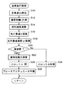
以下、このように構成された走行制御装置の制御内容について説明する。図2を参照すると、追尾走行制御ルーチンのフローチャートが示されており、以下図2を参照して、本発明に係る追尾走行制御の制御手順を説明する。
追尾走行切換操作スイッチ38がセット側に操作され、追尾走行制御が開始されると、先ず、ステップS10において、自車、即ち車両1の車速Vaを上記車輪速センサ32,32からの情報に基づき算出する。詳しくは、車速Vaは、例えば次式(1)より算出される。
【0017】
Va=(VSR+VSL)/2 …(1)
そして、スキャン式レーザレーダ2とCCDカメラ4からの情報に基づいて先行車両が認識され、ステップS12において、スキャン式レーザレーダ2によって自車から先行車までの距離、即ち車間距離Lが精度よく検出される。
そして、ステップS14において、上記車間距離情報Lに基づき、自車と先行車との相対速度が演算される。詳しくは、相対速度は、当該ルーチンを前回実行したときの車間距離情報Lの前回値と今回値との変化量ΔLに基づいて演算される。変化量ΔLが正であれば自車は先行車から離れつつあるとみなせ、変化量ΔLが負であれば自車は先行車に接近しているとみなすことができる。
【0018】
ステップS16では、上記自車の車速Vaと相対速度とから先行車速Vfが演算される。そして、次のステップS18では、上記先行車速Vfを微分処理して先行車減速度αfを演算する(先行車減速度検出手段)。詳しくは、先行車減速度αfは、当該ルーチンを前回実行したときの先行車速情報Vfの前回値と今回値との変化量ΔVfから演算される。
【0019】
次のステップS20では、自車を減速すべきか否かの判別を行う。つまり、ここでは、上記変化量ΔLが負となって自車が先行車に接近しており、車両1を減速させる必要があるか否かを判別する。
ステップS20の判別結果が偽(No)で、上記変化量ΔLが正であり、自車を減速させる必要がないと判定される場合には、次にステップS28に進み、車間距離Lが後述の目標車間距離Lsとなるようスロットルアクチュエータ12、つまりスロットルバルブ8を開閉操作し、加速制御を行う。
【0020】
一方、ステップS20の判別結果が真(Yes)で、自車を減速すべき状況にあると判定される場合には、次にステップS22に進む。
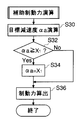
ステップS22では、補助制動力の演算を行う。つまり、自車を減速すべき状況にあるときには、上記ブレーキアクチュエータ30を自動的に作動させ、サービスブレーキ24による制動補助を行うようにするのであるが、ここでは、この際付加される制動力を算出する。この補助制動力の演算は図3の補助制動力演算サブルーチンが実行される。以下、補助制動力演算の処理手順について説明する。
【0021】
図3のステップS30では、自車の目標減速度αaを演算する(目標減速度演算手段)。目標減速度αaは、状況に応じて次式(2),(3)から算出される。
先行車が減速している場合:
αa=Va2/{2・(L−Ls)+(Vf2/αf)} …(2)
先行車が定速走行或いは停止している場合:
αa=(Va−Vf)2/{2・(L−Ls)} …(3)
ここに、Vaは自車速、Vfは先行車速、Lは車間距離、αfは先行車減速度である。また、Lsは目標車間距離であり、車速Vに応じて予め設定された値である。詳しくは、車速Vに応じて先行車と自車との目標車間時間が予め交通流調査等により得られたデータに基づき所定値t1(例えば、1.5sec)に設定されており、目標車間距離Lsはこの目標車間時間t1に基づいて設定されている。
【0022】
以上のように、目標減速度αaが演算されたら、次にステップS32に進む。ステップS32では、目標減速度αaが所定値X1(所定減速度であって、例えば、0.24G)以上であるか否かを判別する。この所定値X1(例えば、0.24G)は、上記目標車間時間t1(例えば、1.5sec)等に応じて予め設定された値であるが、これについては後述する。
【0023】
ステップS32の判別結果が偽(No)で、目標減速度αaが所定値X1(例えば、0.24G)より小さい場合には、次にステップS36に進み、目標減速度αaに応じて制動力、即ち補助制動力を算出する。
そして、図2中のステップS24において、スロットルアクチュエータ12に上記補助制動力に応じた信号を供給してスロットルバルブ8を閉作動させ、ステップS26において、ブレーキアクチュエータ30に上記補助制動力に応じた信号を供給する(制動制御手段)。これにより、ブレーキアクチュエータ30が補助制動力に応じた量だけ自動的に駆動することになり、サービスブレーキ24による制動補助が良好且つ適正に実施されることになる。この場合には、ドライバがブレーキペダル28を操作しなくても、車両1は良好に先行車に追尾して走行する。
【0024】
一方、ステップS32の判別結果が真(Yes)で、目標減速度αaが所定値X1以上である場合には、次にステップS34に進み、目標減速度αaを所定値X1(例えば、0.24G)に設定(クリップ)する。そして、ステップS36において、該所定値X1(例えば、0.24G)に基づき補助制動力を算出し、この所定値X1(例えば、0.24G)に応じた補助制動力に基づいてブレーキアクチュエータ30を自動的に駆動する(制動制御手段)。この場合、車両1を先行車に良好に追尾させるためには、さらにドライバがブレーキペダル28を操作することになる。
【0025】
以上のようにして追尾走行制御の制御が実施されることになるが、以下、目標減速度αaが所定値X1(例えば、0.24G)以上である場合に目標減速度αaを所定値X1(例えば、0.24G)でクリップする理由について詳細に説明する。
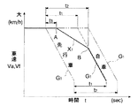
図4を参照すると、自車が目標車間時間t1(例えば、1.5sec)で追尾走行制御されているときに、先行車が減速度G1(例えば、0.7G)で減速した場合の先行車の車速Vfと自車の車速Vaの時間変化がそれぞれ示されており、以下、当該図4に基づいて説明する。
【0026】
本来、先行車が減速度G1(例えば、0.7G)のような大きな減速度で急制動したときには(一点鎖線で示す)、自車を先行車と接触させないよう減速させるためには、先行車が制動を開始した後目標車間時間t1(例えば、1.5sec)以内に、先行車に合わせて目標減速度αaを同一の減速度G1として自車の制動を行うようにすればよい(破線で示す)。従って、この場合、減速度G1に応じた補助制動力でもって車両1を自動的に制動させるようにすればよい。
【0027】
しかしながら、急激な制動を全て自動的に実施することは、必ずしもドライバの意思に沿ったものとはならず、ドライバ等の車両1の乗員に違和感を与えることになり好ましいことではない。故に、可能な限りドライバがブレーキペダル28を操作して制動を行うようにするの望ましい。
ところが、目標車間時間t1(例えば、1.5sec)のように短い車間時間内に、ドライバが先行車の急制動を判断し且つブレーキペダル28を操作することは容易なことではなく、通常は、操作に要する余裕空走時間(余裕時間)として少なくとも所定時間t2(所定の余裕時間であって、例えば、2.0sec)程度が必要とされている。
【0028】
そこで、本発明では、目標車間時間が値t1(例えば、1.5sec)と短い時間でありながら、余裕空走時間t2(例えば、2.0sec)を確保するようにしており、この余裕空走時間t2を確保するのに所定値X1(例えば、0.24G)が重要となっている。以下、所定値X1(例えば、0.24G)について説明する。ここで改めて図4を参照すると、余裕空走時間t2(例えば、2.0sec)経過時において自車の車速Vaが少なくとも図中の破線上のB点にあれば、ドライバが余裕空走時間t2経過した時点でブレーキペダル28を操作したとしても、その後自車の車速Vaがブレーキペダル28の操作で上記破線に沿い良好に減少可能であることがわかる。
【0029】
従って、余裕空走時間t2を確保するためには、自車の車速Vaが破線上のB点に達するまで、補助制動によって徐々に車両1を減速させておけばよいことになり、このとき補助制動に要求される減速度が、即ち所定値X1(例えば、0.24G)である。より詳しくは、ブレーキアクチュエータ30の制御遅れ時間t3(例えば、0.5sec)を考慮すると、余裕空走時間t2(例えば、2.0sec)を確保すべく補助制動に必要とされる減速度は、図中A点とB点とを結ぶ線の傾きとして求められることになり、補助制動の減速度はこの傾きから所定値X1(例えば、0.24G)として一義に決定される。
【0030】
つまり、所定値X1(例えば、0.24G)は、先行車が急制動したような場合であっても、余裕空走時間t2(例えば、2.0sec)を確保するために補助制動に必要且つ十分な減速度を意味しており、これにより、少なくとも該所定値X1(例えば、0.24G)の減速度で補助制動を行えば、目標車間時間が値t1(例えば、1.5sec)と短い場合でも、先行車の制動状況如何に拘わらず、車両1のドライバは十分な時間的余裕をもって確実にブレーキペダル28の操作により自車を減速させ先行車に追従させることが可能となるのである。
【0031】
従って、図4中には、例えば、目標車間時間を余裕空走時間と同じ値t2(例えば、2.0sec)に設定したときに自車の目標減速度αaをG1(例えば、0.7G)で減速した場合の自車速Vaの時間変化をも併せて示してあり(二点鎖線で示す)、この場合には、補助制動を行わなくてもブレーキペダル28の操作に十分な時間的余裕があり、良好に自車を先行車との接触なく減速することができるのであるが、上記本発明に係る追尾走行制御を実施することで、目標車間時間が値t1(例えば、1.5sec)と短いような場合であっても、上記目標車間時間を値t2とした場合と同様に余裕空走時間t2(例えば、2.0sec)を確保して時間的余裕を有しながら、ブレーキペダル28の操作によって自車を先行車との接触なく良好且つ安全に減速させることが可能となる。
【0032】
なお、ここに、所定値X1(例えば、0.24G)は、減速度G1(例えば、0.7G)でもって極めて急な制動を行った場合であっても確実に余裕空走時間t2(例えば、2.0sec)を確保可能な減速度であるため、先行車の減速度が値G1より小さい領域(例えば、0.24G〜0.7G)にある場合には、当然のことながら、表1に例示するように、余裕空走時間は値t2よりも長くなり、ドライバがブレーキペダル28を操作するまでに十分な余裕時間が確保されることとなる。
【0033】
【表1】

また、例えば、交通状況等によって目標車間時間が値t1(例えば、1.5sec)よりもさらに短く或いは長く変更されることも考えられるが、このような場合であっても、上述の手法に基づき、図4上で自車の目標減速度αaが値G1(例えば、0.7G)とされたときの余裕空走時間t2(例えば、2.0sec)経過時のB’点を求めるようにすれば、このB’点と上記A点とに基づいて補助制動に必要な減速度(所定減速度)を容易に算出し設定変更することができる。従って、目標車間時間が変更された場合であっても、先行車の制動状況に拘わらず、常に余裕空走時間t2(例えば、2.0sec)を保持し余裕をもってブレーキペダル28を操作することができ、車両1を良好且つ安全に減速させることが可能である。
【0035】
【発明の効果】
以上詳細に説明したように、請求項1の車両の走行制御装置によれば、目標減速度が所定減速度以上のときには減速度が所定減速度にクリップされてアクチュエータにより自動的に付加される制動力が制限されるので、先行車両が急な制動をしたような場合でも、それに応じて自車両が自動的に急制動してしまうことを防止でき、ドライバに違和感を与えないようにできる。
【0036】
また、アクチュエータによる自動制動を補助制動手段として機能させることで、ブレーキペダル操作までの余裕時間(余裕空走時間)を拡大することができ、ドライバのブレーキペダル操作の遅れを回避して減速制御時の車両の走行安全性を向上させることができる。
そして、先行車両の減速度が大きく、自車両の目標減速度が大きいような場合であっても、ブレーキペダルを操作するまでの余裕時間を常に最低限必要且つ十分な所定の余裕時間以上にでき、余裕時間の不足なくドライバのブレーキペダル操作の遅れを良好に回避して車両の走行安全性を確保することができる。
【図面の簡単な説明】
【図1】車両に搭載された本発明に係る走行制御装置の概略構成図である。
【図2】本発明に係る追尾走行制御ルーチンを示すフローチャートである。
【図3】図2中の補助制動力演算のサブルーチンを示すフローチャートである。
【図4】自車が目標車間時間t1で追尾走行制御されているときに、先行車が減速度G1で減速した場合の先行車の車速Vfと、本発明に係る走行制御を実施した場合の自車の車速Vaの時間変化を示す図である。
【符号の説明】
1 車両(自車両)
2 スキャン式レーザレーダ
4 CCDカメラ
24 サービスブレーキ(制動装置)
28 ブレーキペダル
30 ブレーキアクチュエータ
32 車輪速センサ
50 電子制御ユニット(ECU)[0001]
BACKGROUND OF THE INVENTION
The present invention relates to a vehicle travel control device, and more particularly to a deceleration control technology during travel control.
[0002]
[Related background]
In recent years, in order to reduce the driving operation of an automobile, a travel control device including an inter-vehicle distance control device has been developed and put into practical use for tracking the preceding vehicle.
The travel control device including the inter-vehicle distance control device detects the inter-vehicle distance between the host vehicle and the preceding vehicle based on information from a front recognition device such as a camera or a laser radar. The vehicle speed is adjusted by adjusting the engine output or the like so that the set target inter-vehicle distance is obtained, and the preceding vehicle is tracked.
[0003]
Furthermore, recently, a device capable of automatically operating the brake device when the preceding vehicle decelerates and thereby decelerating the host vehicle is disclosed in JP-A-7-65297.
[0004]
[Problems to be solved by the invention]
By the way, in the device disclosed in the above publication, even when the preceding vehicle is greatly decelerated, the host vehicle is automatically braked by the brake device.
However, when the preceding vehicle decelerates, it may not be in the braking state according to the driver's intention to completely automatically brake the own vehicle according to the deceleration, which makes the driver and the vehicle occupant feel uncomfortable. There is a possibility of giving, which is not preferable.
[0005]
Therefore, it is considered that when the deceleration rate is large, the brake pedal operation, that is, normal braking based on the driver's intention is performed even during the tracking traveling control.
However, considering the driver's response to the deceleration of the preceding vehicle, that is, it takes time for the driver to start operating the brake pedal, the brake pedal operation by the driver tends to be delayed. It is necessary to secure a spare time.
[0006]
The present invention has been made based on the above-described circumstances, and an object of the present invention is to provide a vehicle travel control device that can realize braking according to the driver's intention during deceleration during travel control and has high safety. There is to do.
[0007]
[Means for Solving the Problems]
In order to achieve the above-described object, in the invention of claim 1, when deceleration control is performed in a vehicle travel control device that performs tracking travel control of a preceding vehicle traveling in the same travel lane as the host vehicle, First, the preceding vehicle deceleration detecting means detects the deceleration of the preceding vehicle, and the target deceleration calculating means calculates the target deceleration of the host vehicle according to the deceleration of the preceding vehicle. Then, when the preceding vehicle is decelerating, the actuator is controlled by the braking control means to apply a braking force corresponding to the target deceleration when the target deceleration is less than the predetermined deceleration, while the target deceleration is When the predetermined deceleration is exceeded, the actuator is controlled to apply a braking force corresponding to the predetermined deceleration.
At this time, the predetermined deceleration generates a braking force corresponding to the predetermined deceleration when the inter-vehicle time between the host vehicle and the preceding vehicle is shorter than a predetermined margin time required to start the operation of the brake pedal. When it is assumed that the own vehicle is decelerated by operating the actuator, the margin time until the brake pedal operation is started (the margin idle running time) is set to a deceleration that ensures at least a predetermined margin time.
[0008]
Thus, when the deceleration is clipped to the predetermined deceleration when the target deceleration is equal to or greater than the predetermined deceleration, the braking force automatically applied by the actuator is limited, and the automatic braking operates the brake pedal. It will function only as an auxiliary braking means until the host vehicle suddenly brakes, and the host vehicle will not automatically brake suddenly, preventing the driver from feeling uncomfortable. The
[0009]
In addition, making the automatic braking by the actuator function as an auxiliary braking means increases the margin time until the driver operates the brake pedal (the margin idle time), thus avoiding the delay of the driver's brake pedal operation. Thus, the traveling safety of the vehicle during the deceleration control is improved .
[0010]
And , in the case where the deceleration of the preceding vehicle is large and the target deceleration of the own vehicle is large, the inter-vehicle time between the own vehicle and the preceding vehicle is at least required until the driver starts operating the brake pedal. Even when it is shorter than the specified margin time, the margin time required to operate the brake pedal is set to the minimum necessary and sufficient predetermined margin time, and the driver's delay in brake pedal operation can be avoided well without lack of margin time. The
[0011]
DETAILED DESCRIPTION OF THE INVENTION
Referring to FIG. 1, a schematic configuration diagram of a travel control device according to the present invention mounted on a vehicle 1 is shown. The configuration of the travel control device will be described below with reference to FIG.
A scanning system that emits a laser beam toward the front of the vehicle 1, recognizes an object positioned in front of the vehicle 1 by scanning the laser beam, and further measures a distance to the object. A laser radar 2 is provided. A
[0012]
The
[0013]
A pair of left and right front wheels (drive wheels) 20 and 20 and a pair of left and right rear wheels (sub wheels) 22 and 22 are provided with service brakes (braking devices) 24 such as hydraulic disc brakes, respectively. It is connected to a
[0014]
Further,
The
[0015]
The ECU 50 is a main control device that controls various controls of the vehicle 1. As shown in the figure, various sensors and switches such as the scanning laser radar 2, the
[0016]
Hereinafter, the control content of the traveling control device configured as described above will be described. Referring to FIG. 2, there is shown a flowchart of the tracking travel control routine. Hereinafter, the control procedure of the tracking travel control according to the present invention will be described with reference to FIG.
When the tracking travel switching operation switch 38 is operated to the set side and the tracking travel control is started, first, in step S10, the vehicle speed Va of the own vehicle, that is, the vehicle 1 is based on the information from the
[0017]
Va = (VSR + VSL) / 2 (1)
Then, the preceding vehicle is recognized based on the information from the scanning laser radar 2 and the
In step S14, based on the inter-vehicle distance information L, the relative speed between the host vehicle and the preceding vehicle is calculated. Specifically, the relative speed is calculated based on a change amount ΔL between the previous value and the current value of the inter-vehicle distance information L when the routine is executed last time. If the amount of change ΔL is positive, it can be considered that the host vehicle is moving away from the preceding vehicle, and if the amount of change ΔL is negative, the host vehicle can be regarded as approaching the preceding vehicle.
[0018]
In step S16, the preceding vehicle speed Vf is calculated from the vehicle speed Va of the host vehicle and the relative speed. In the next step S18, the preceding vehicle speed Vf is differentiated to calculate a preceding vehicle deceleration rate αf (preceding vehicle deceleration detecting means). Specifically, the preceding vehicle deceleration rate αf is calculated from the amount of change ΔVf between the previous value and the current value of the preceding vehicle speed information Vf when the routine was executed last time.
[0019]
In the next step S20, it is determined whether or not the own vehicle should be decelerated. That is, here, it is determined whether or not the change amount ΔL is negative and the vehicle is approaching the preceding vehicle, and the vehicle 1 needs to be decelerated.
If the determination result in step S20 is false (No) and the change amount ΔL is positive and it is determined that the host vehicle does not need to be decelerated, the process proceeds to step S28, where the inter-vehicle distance L is set to be described later. The
[0020]
On the other hand, if the determination result of step S20 is true (Yes) and it is determined that the vehicle is in a situation to decelerate, the process proceeds to step S22.
In step S22, an auxiliary braking force is calculated. That is, when the host vehicle is in a situation to decelerate, the
[0021]
In step S30 of FIG. 3, the target deceleration αa of the own vehicle is calculated (target deceleration calculating means). The target deceleration rate αa is calculated from the following equations (2) and (3) according to the situation.
When the preceding vehicle is decelerating:
αa = Va 2 / {2 · (L−Ls) + (Vf 2 / αf)} (2)
When the preceding vehicle is running at a constant speed or stopped:
αa = (Va−Vf) 2 / {2 · (L−Ls)} (3)
Here, Va is the own vehicle speed, Vf is the preceding vehicle speed, L is the inter-vehicle distance, and αf is the preceding vehicle deceleration. Ls is a target inter-vehicle distance and is a value set in advance according to the vehicle speed V. Specifically, the target inter-vehicle time between the preceding vehicle and the host vehicle is set to a predetermined value t1 (for example, 1.5 sec) based on data obtained in advance by a traffic flow survey or the like according to the vehicle speed V, and the target inter-vehicle distance Ls is set based on the target inter-vehicle time t1.
[0022]
As described above, after the target deceleration rate αa is calculated, the process proceeds to step S32. In step S32, it is determined whether or not the target deceleration rate αa is equal to or greater than a predetermined value X1 (a predetermined deceleration rate, for example, 0.24G). The predetermined value X1 (for example, 0.24G) is a value set in advance according to the target inter-vehicle time t1 (for example, 1.5 seconds), which will be described later.
[0023]
If the determination result in step S32 is false (No) and the target deceleration rate αa is smaller than a predetermined value X1 (for example, 0.24G), the process proceeds to step S36, where the braking force, That is, the auxiliary braking force is calculated.
In step S24 in FIG. 2, a signal corresponding to the auxiliary braking force is supplied to the
[0024]
On the other hand, if the determination result in step S32 is true (Yes) and the target deceleration rate αa is greater than or equal to the predetermined value X1, the process proceeds to step S34, where the target deceleration rate αa is set to the predetermined value X1 (for example, 0.24G). (Clip). In step S36, an auxiliary braking force is calculated based on the predetermined value X1 (for example, 0.24G), and the
[0025]
The tracking control is executed as described above. Hereinafter, when the target deceleration rate αa is a predetermined value X1 (for example, 0.24 G) or more, the target deceleration rate αa is set to the predetermined value X1 ( For example, the reason for clipping at 0.24G) will be described in detail.
Referring to FIG. 4, the preceding vehicle when the preceding vehicle decelerates at a deceleration G1 (for example, 0.7 G) when the host vehicle is tracking-controlled at the target inter-vehicle time t1 (for example, 1.5 sec). Changes in the vehicle speed Vf of the vehicle and the vehicle speed Va of the own vehicle are respectively shown, and will be described below with reference to FIG.
[0026]
Originally, when the preceding vehicle suddenly brakes with a large deceleration such as deceleration G1 (for example, 0.7 G) (indicated by a one-dot chain line), in order to decelerate the own vehicle so as not to contact the preceding vehicle, the preceding vehicle Within a target inter-vehicle time t1 (for example, 1.5 sec) after the vehicle starts braking, the vehicle may be braked with the same deceleration G1 as the target deceleration αa in accordance with the preceding vehicle (indicated by a broken line). Show). Therefore, in this case, the vehicle 1 may be automatically braked with an auxiliary braking force corresponding to the deceleration G1.
[0027]
However, it is not preferable that all the sudden braking is automatically performed because it does not necessarily conform to the driver's intention, and the driver and other passengers of the vehicle 1 feel uncomfortable. Therefore, it is desirable that the driver operates the
However, it is not easy for the driver to determine the sudden braking of the preceding vehicle and to operate the
[0028]
Therefore, in the present invention, while the target inter-vehicle time is as short as the value t1 (for example, 1.5 sec), the spare idle time t2 (for example, 2.0 sec) is ensured. A predetermined value X1 (for example, 0.24 G) is important for securing the time t2. Hereinafter, the predetermined value X1 (for example, 0.24G) will be described. Referring again to FIG. 4, if the vehicle speed Va of the host vehicle is at least at point B on the broken line in the figure when the marginal idle time t2 (for example, 2.0 seconds) has elapsed, the marginal idle time t2 Even if the
[0029]
Therefore, in order to secure the spare idle time t2, it is sufficient to gradually decelerate the vehicle 1 by auxiliary braking until the vehicle speed Va of the host vehicle reaches the point B on the broken line. The deceleration required for braking is a predetermined value X1 (for example, 0.24G). More specifically, in consideration of the control delay time t3 (for example, 0.5 sec) of the
[0030]
In other words, the predetermined value X1 (for example, 0.24G) is necessary for auxiliary braking in order to ensure a spare idle running time t2 (for example, 2.0 seconds) even when the preceding vehicle suddenly brakes. This means a sufficient deceleration. Thus, if auxiliary braking is performed at a deceleration of at least the predetermined value X1 (for example, 0.24 G), the target inter-vehicle time is as short as a value t1 (for example, 1.5 sec). Even in this case, regardless of the braking condition of the preceding vehicle, the driver of the vehicle 1 can decelerate the vehicle by operating the
[0031]
Therefore, in FIG. 4, for example, when the target inter-vehicle time is set to the same value t2 (for example, 2.0 sec) as the spare idle time, the target deceleration αa of the own vehicle is set to G1 (for example, 0.7 G). The time change of the vehicle speed Va when the vehicle decelerates is also shown (indicated by a two-dot chain line). In this case, there is a sufficient time margin for operating the
[0032]
Here, the predetermined value X1 (for example, 0.24G) is surely enough for the surplus idle time t2 (for example, even when extremely slow braking is performed with the deceleration G1 (for example, 0.7G)). 2.0 sec.), If the deceleration of the preceding vehicle is in a region smaller than the value G1 (for example, 0.24G to 0.7G), it is natural that Table 1 As shown in FIG. 5, the spare idle time is longer than the value t2, and a sufficient spare time is ensured until the driver operates the
[0033]
[Table 1]
In addition, for example, the target inter-vehicle time may be changed to be shorter or longer than the value t1 (for example, 1.5 sec) depending on the traffic condition or the like. In FIG. 4, the point B ′ when the idle idle time t2 (for example, 2.0 sec) has elapsed when the target deceleration rate αa of the own vehicle is set to the value G1 (for example, 0.7 G) is obtained. For example, the deceleration required for the auxiliary braking (predetermined deceleration) can be easily calculated and changed based on the B ′ point and the A point. Therefore, even when the target inter-vehicle time is changed, the
[0035]
【The invention's effect】
As described above in detail, according to the vehicle travel control apparatus of claim 1, when the target deceleration is equal to or greater than the predetermined deceleration, the deceleration is clipped to the predetermined deceleration and automatically added by the actuator. Since the power is limited, even when the preceding vehicle suddenly brakes, it is possible to prevent the own vehicle from automatically braking suddenly and to prevent the driver from feeling uncomfortable.
[0036]
In addition, by allowing automatic braking by the actuator to function as an auxiliary braking means, it is possible to increase the time to brake pedal operation (extra idle time) and avoid delays in driver brake pedal operation during deceleration control. The traveling safety of the vehicle can be improved.
Then, a large deceleration of the previous row vehicle, even when the target deceleration of the vehicle is large, the margin time until the operation of the brake pedal always minimum and sufficient to more than a predetermined margin h Thus, it is possible to satisfactorily avoid the delay of the driver's brake pedal operation without lack of margin time, and to ensure the traveling safety of the vehicle.
[Brief description of the drawings]
FIG. 1 is a schematic configuration diagram of a travel control device according to the present invention mounted on a vehicle.
FIG. 2 is a flowchart showing a tracking traveling control routine according to the present invention.
FIG. 3 is a flowchart showing a subroutine of auxiliary braking force calculation in FIG.
FIG. 4 shows the vehicle speed Vf of the preceding vehicle when the preceding vehicle decelerates at the deceleration G1 and the traveling control according to the present invention when the own vehicle is being tracked at the target inter-vehicle time t1. It is a figure which shows the time change of the vehicle speed Va of the own vehicle.
[Explanation of symbols]
1 Vehicle (own vehicle)
2
28
Claims (1)
自車両に制動力を付加する制動装置と、
前記制動装置を自動的に作動させるアクチュエータと、
先行車両の減速度を検出する先行車減速度検出手段と、
前記先行車両の減速度に応じて自車両の目標減速度を演算する目標減速度演算手段と、
先行車両が減速しているとき、前記目標減速度が所定減速度未満のときには前記目標減速度に応じた制動力を付加すべく前記アクチュエータを作動制御する一方、前記目標減速度が前記所定減速度以上のときには該所定減速度に応じただけの制動力を付加すべく前記アクチュエータを作動制御する制動制御手段とを備え、
前記所定減速度は、自車両と先行車両間の車間時間がドライバによるブレーキペダルの操作開始までに最低限必要とされる所定の余裕時間より短いときには、該所定減速度に応じた制動力を発生するよう前記アクチュエータを作動させて自車両を減速させたと仮定した場合に前記ブレーキペダルの操作開始までの余裕時間が少なくとも前記所定の余裕時間以上確保される減速度に設定されてなることを特徴とする車両の走行制御装置。In a vehicle travel control device that performs tracking travel control of a preceding vehicle traveling in the same travel lane as the host vehicle,
A braking device for applying braking force to the host vehicle;
An actuator for automatically operating the braking device;
Preceding vehicle deceleration detection means for detecting the deceleration of the preceding vehicle;
Target deceleration calculation means for calculating the target deceleration of the host vehicle according to the deceleration of the preceding vehicle;
When the preceding vehicle is decelerating, when the target deceleration is less than the predetermined deceleration, the actuator is controlled to apply a braking force according to the target deceleration, while the target deceleration is the predetermined deceleration. Bei example a brake control means for operation control of the actuator so as to braking force is applied only according to the predetermined deceleration when the above
The predetermined deceleration generates a braking force corresponding to the predetermined deceleration when the inter-vehicle time between the host vehicle and the preceding vehicle is shorter than a predetermined margin time required for the driver to start operating the brake pedal. When it is assumed that the own vehicle is decelerated by operating the actuator, the vehicle is set to a deceleration at which a margin time until the start of operation of the brake pedal is secured at least the predetermined margin time. A vehicle travel control device.
Priority Applications (4)
| Application Number | Priority Date | Filing Date | Title |
|---|---|---|---|
| JP16479897A JP3832526B2 (en) | 1997-06-20 | 1997-06-20 | Vehicle travel control device |
| US09/099,140 US6134497A (en) | 1997-06-20 | 1998-06-18 | Vehicle running control apparatus and vehicle running control method |
| KR1019980022861A KR100276964B1 (en) | 1997-06-20 | 1998-06-18 | Driving control device of vehicle |
| DE19827445A DE19827445A1 (en) | 1997-06-20 | 1998-06-19 | Drive control device for motor vehicle |
Applications Claiming Priority (1)
| Application Number | Priority Date | Filing Date | Title |
|---|---|---|---|
| JP16479897A JP3832526B2 (en) | 1997-06-20 | 1997-06-20 | Vehicle travel control device |
Publications (2)
| Publication Number | Publication Date |
|---|---|
| JPH1111273A JPH1111273A (en) | 1999-01-19 |
| JP3832526B2 true JP3832526B2 (en) | 2006-10-11 |
Family
ID=15800143
Family Applications (1)
| Application Number | Title | Priority Date | Filing Date |
|---|---|---|---|
| JP16479897A Expired - Lifetime JP3832526B2 (en) | 1997-06-20 | 1997-06-20 | Vehicle travel control device |
Country Status (4)
| Country | Link |
|---|---|
| US (1) | US6134497A (en) |
| JP (1) | JP3832526B2 (en) |
| KR (1) | KR100276964B1 (en) |
| DE (1) | DE19827445A1 (en) |
Families Citing this family (35)
| Publication number | Priority date | Publication date | Assignee | Title |
|---|---|---|---|---|
| US6353812B2 (en) | 1998-02-19 | 2002-03-05 | Certco, Inc. | Computer-based method and system for aiding transactions |
| DE19749296C5 (en) * | 1997-11-07 | 2007-01-11 | Daimlerchrysler Ag | Method for determining a tripping threshold value for an automatic braking process |
| DE19940252A1 (en) * | 1998-10-27 | 2000-06-15 | Continental Teves Ag & Co Ohg | Device and method for controlling the braking force of a brake system |
| DE19859284A1 (en) * | 1998-12-22 | 2000-06-29 | Bosch Gmbh Robert | Method and device for speed and distance control of a motor vehicle |
| DE19936436A1 (en) * | 1999-03-04 | 2001-01-04 | Continental Teves Ag & Co Ohg | Procedure for recognizing an emergency braking situation |
| EP1792799A3 (en) * | 1999-07-01 | 2008-10-22 | Hitachi, Ltd. | Apparatus for controlling run of a car, and car using the apparatus |
| DE19937942B4 (en) * | 1999-08-11 | 2005-12-22 | Daimlerchrysler Ag | Method and control system for distance and speed control of a vehicle |
| DE19960782A1 (en) * | 1999-12-16 | 2001-06-21 | Mannesmann Vdo Ag | Acceleration monitoring method for longitudinal dynamics control or regulation in motor vehicles |
| DE10007501A1 (en) * | 2000-02-18 | 2001-09-13 | Daimler Chrysler Ag | Road traffic monitoring method for automobile detects road lane, velocity and/or relative spacing of each preceding vehicle |
| DE10025678B4 (en) * | 2000-05-24 | 2006-10-19 | Daimlerchrysler Ag | Camera-based precrash detection system |
| US6502053B1 (en) * | 2000-06-12 | 2002-12-31 | Larry Hardin | Combination passive and active speed detection system |
| JP3809756B2 (en) * | 2000-08-29 | 2006-08-16 | トヨタ自動車株式会社 | Travel control device |
| JP3611028B2 (en) * | 2000-08-29 | 2005-01-19 | トヨタ自動車株式会社 | Travel control device |
| DE10118708A1 (en) * | 2001-04-12 | 2002-10-17 | Bosch Gmbh Robert | Regulating motor vehicle speed involves outputting signal for biasing brake system if acceleration demand signal falls below threshold above value at which brake system is activated |
| DE10151717A1 (en) * | 2001-10-19 | 2003-04-30 | Bayerische Motoren Werke Ag | Cruise control system with distance sensors for a motor vehicle |
| JP3880841B2 (en) * | 2001-11-15 | 2007-02-14 | 富士重工業株式会社 | Outside monitoring device |
| AU2002309107A1 (en) * | 2002-06-07 | 2003-12-22 | Neelam Agarwal | Navdurga vehicle safety systems |
| US6834232B1 (en) | 2003-07-30 | 2004-12-21 | Ford Global Technologies, Llc | Dual disimilar sensing object detection and targeting system |
| US7389171B2 (en) * | 2003-12-22 | 2008-06-17 | Ford Global Technologies Llc | Single vision sensor object detection system |
| JP4543910B2 (en) | 2004-01-29 | 2010-09-15 | トヨタ自動車株式会社 | Vehicle deceleration control device |
| JP4532181B2 (en) | 2004-06-24 | 2010-08-25 | 日産自動車株式会社 | VEHICLE DRIVE OPERATION ASSISTANCE DEVICE AND VEHICLE HAVING VEHICLE DRIVE OPERATION ASSISTANCE DEVICE |
| JP4831509B2 (en) * | 2005-01-25 | 2011-12-07 | ヴアブコ・ゲゼルシヤフト・ミツト・ベシユレンクテル・ハフツング | Collision warning method in automobile |
| WO2008043852A1 (en) * | 2006-10-13 | 2008-04-17 | Continental Teves Ag & Co. Ohg | System for determining objects |
| JP2009107574A (en) * | 2007-10-31 | 2009-05-21 | Toyota Motor Corp | Control device for vehicular traveling |
| JP4564041B2 (en) * | 2007-11-27 | 2010-10-20 | 本田技研工業株式会社 | Vehicle travel control device |
| US9963127B2 (en) * | 2010-01-15 | 2018-05-08 | Volvo Car Corporation | Collision mitigation system and method for braking a vehicle |
| US8972147B2 (en) | 2011-01-10 | 2015-03-03 | Bendix Commercial Vehicle Systems Llc | ACC and AM braking range variable based on internal and external factors |
| KR20130009132A (en) * | 2011-07-14 | 2013-01-23 | 현대자동차주식회사 | Apparatus and method for controlling a vehicle using visible light communication |
| US8510029B2 (en) * | 2011-10-07 | 2013-08-13 | Southwest Research Institute | Waypoint splining for autonomous vehicle following |
| JP5267963B1 (en) * | 2011-11-02 | 2013-08-21 | トヨタ自動車株式会社 | Braking control device |
| US10737665B2 (en) * | 2012-08-28 | 2020-08-11 | Ford Global Technologies, Llc | Vehicle braking based on external object communications |
| CN104648359B (en) * | 2015-03-16 | 2017-05-31 | 青岛建邦供应链股份有限公司 | A kind of Intelligent brake system |
| CN105292118A (en) * | 2015-11-10 | 2016-02-03 | 中国重汽集团济南动力有限公司 | Heavy-duty vehicle hill-start assist control method |
| JP7151672B2 (en) * | 2019-09-11 | 2022-10-12 | いすゞ自動車株式会社 | vehicle controller |
| JP7343844B2 (en) * | 2020-05-26 | 2023-09-13 | トヨタ自動車株式会社 | Driving support device |
Family Cites Families (14)
| Publication number | Priority date | Publication date | Assignee | Title |
|---|---|---|---|---|
| JP2722746B2 (en) * | 1990-01-29 | 1998-03-09 | 日産自動車株式会社 | Automatic brake device |
| US5165497A (en) * | 1991-02-26 | 1992-11-24 | Chi C Y | Automatic safety driving distance control device for a vehicle |
| DE4209060C2 (en) * | 1992-03-20 | 1994-12-15 | Daimler Benz Ag | Method for regulating the distance between moving motor vehicles |
| JP3232724B2 (en) * | 1992-12-08 | 2001-11-26 | 株式会社デンソー | Inter-vehicle distance control device |
| JPH07251651A (en) * | 1994-03-15 | 1995-10-03 | Nissan Motor Co Ltd | Intervehicle distance control device |
| US5572449A (en) * | 1994-05-19 | 1996-11-05 | Vi&T Group, Inc. | Automatic vehicle following system |
| JP3380624B2 (en) * | 1994-09-14 | 2003-02-24 | マツダ株式会社 | Vehicle running state detection device |
| JP3044524B2 (en) * | 1995-05-23 | 2000-05-22 | 本田技研工業株式会社 | Method for detecting objects in vehicles |
| JPH08318765A (en) * | 1995-05-25 | 1996-12-03 | Hitachi Ltd | Controlling device and method for intelligent automobile |
| JP3588868B2 (en) * | 1995-08-04 | 2004-11-17 | 日産自動車株式会社 | Driving force control device for vehicles |
| JP3726923B2 (en) * | 1996-04-10 | 2005-12-14 | 富士重工業株式会社 | Vehicle driving support device |
| JP3805832B2 (en) * | 1996-07-10 | 2006-08-09 | 富士重工業株式会社 | Vehicle driving support device |
| JP3477015B2 (en) * | 1996-12-25 | 2003-12-10 | トヨタ自動車株式会社 | Inter-vehicle distance control device |
| DE19744720A1 (en) * | 1997-10-10 | 1999-04-15 | Bosch Gmbh Robert | Controlling vehicle speed with respect to set speed |
-
1997
- 1997-06-20 JP JP16479897A patent/JP3832526B2/en not_active Expired - Lifetime
-
1998
- 1998-06-18 US US09/099,140 patent/US6134497A/en not_active Expired - Lifetime
- 1998-06-18 KR KR1019980022861A patent/KR100276964B1/en not_active IP Right Cessation
- 1998-06-19 DE DE19827445A patent/DE19827445A1/en not_active Ceased
Also Published As
| Publication number | Publication date |
|---|---|
| KR19990007083A (en) | 1999-01-25 |
| US6134497A (en) | 2000-10-17 |
| KR100276964B1 (en) | 2001-02-01 |
| JPH1111273A (en) | 1999-01-19 |
| DE19827445A1 (en) | 1998-12-24 |
Similar Documents
| Publication | Publication Date | Title |
|---|---|---|
| JP3832526B2 (en) | Vehicle travel control device | |
| US7866427B2 (en) | Vehicle multi-stage integrated brake assist for a collision preparation system | |
| US7840354B2 (en) | Method and device for automatically triggering a vehicle deceleration | |
| JP3849430B2 (en) | Vehicle travel control device | |
| US6502908B1 (en) | Control system for a vehicle | |
| EP3789254A1 (en) | Method, device and system for automatic braking of vehicle | |
| JP3952104B2 (en) | Vehicle travel control device | |
| JP3327217B2 (en) | Vehicle running control method | |
| JPH1067256A (en) | Method for controlling speed of vehicle and device thereof | |
| JP2006175941A (en) | Acceleration/deceleration controller | |
| CN110641466B (en) | Vehicle control device | |
| JP3707521B2 (en) | Vehicle travel control device | |
| JP4039062B2 (en) | Parking assistance device | |
| JP3381778B2 (en) | Vehicle running control method | |
| JP3651289B2 (en) | Brake control device | |
| JP3957057B2 (en) | Vehicle traveling control apparatus and method | |
| JP2002166747A (en) | Running controller for vehicle | |
| JP3747989B2 (en) | Vehicle travel control device | |
| JPH11334554A (en) | Run controller for vehicle | |
| JP2000006684A (en) | Vehicle travel control device | |
| JP2778310B2 (en) | Vehicle operating device control device | |
| JPH11348599A (en) | Traveling control device for vehicle | |
| JP4624726B2 (en) | Inter-vehicle distance control device | |
| JP3238588B2 (en) | Inter-vehicle distance control device | |
| JP3557890B2 (en) | Inter-vehicle distance control device |
Legal Events
| Date | Code | Title | Description |
|---|---|---|---|
| A131 | Notification of reasons for refusal |
Free format text: JAPANESE INTERMEDIATE CODE: A131 Effective date: 20040107 |
|
| A02 | Decision of refusal |
Free format text: JAPANESE INTERMEDIATE CODE: A02 Effective date: 20040922 |
|
| A521 | Request for written amendment filed |
Free format text: JAPANESE INTERMEDIATE CODE: A523 Effective date: 20041119 |
|
| A911 | Transfer to examiner for re-examination before appeal (zenchi) |
Free format text: JAPANESE INTERMEDIATE CODE: A911 Effective date: 20041125 |
|
| TRDD | Decision of grant or rejection written | ||
| A01 | Written decision to grant a patent or to grant a registration (utility model) |
Free format text: JAPANESE INTERMEDIATE CODE: A01 Effective date: 20060628 |
|
| A61 | First payment of annual fees (during grant procedure) |
Free format text: JAPANESE INTERMEDIATE CODE: A61 Effective date: 20060711 |
|
| S531 | Written request for registration of change of domicile |
Free format text: JAPANESE INTERMEDIATE CODE: R313531 |
|
| R350 | Written notification of registration of transfer |
Free format text: JAPANESE INTERMEDIATE CODE: R350 |
|
| FPAY | Renewal fee payment (event date is renewal date of database) |
Free format text: PAYMENT UNTIL: 20100728 Year of fee payment: 4 |
|
| FPAY | Renewal fee payment (event date is renewal date of database) |
Free format text: PAYMENT UNTIL: 20110728 Year of fee payment: 5 |
|
| FPAY | Renewal fee payment (event date is renewal date of database) |
Free format text: PAYMENT UNTIL: 20120728 Year of fee payment: 6 |
|
| FPAY | Renewal fee payment (event date is renewal date of database) |
Free format text: PAYMENT UNTIL: 20120728 Year of fee payment: 6 |
|
| FPAY | Renewal fee payment (event date is renewal date of database) |
Free format text: PAYMENT UNTIL: 20130728 Year of fee payment: 7 |
|
| FPAY | Renewal fee payment (event date is renewal date of database) |
Free format text: PAYMENT UNTIL: 20130728 Year of fee payment: 7 |
|
| FPAY | Renewal fee payment (event date is renewal date of database) |
Free format text: PAYMENT UNTIL: 20140728 Year of fee payment: 8 |
|
| EXPY | Cancellation because of completion of term |