JP3829512B2 - Input side disk unit for toroidal type continuously variable transmission - Google Patents
Input side disk unit for toroidal type continuously variable transmission Download PDFInfo
- Publication number
- JP3829512B2 JP3829512B2 JP36910198A JP36910198A JP3829512B2 JP 3829512 B2 JP3829512 B2 JP 3829512B2 JP 36910198 A JP36910198 A JP 36910198A JP 36910198 A JP36910198 A JP 36910198A JP 3829512 B2 JP3829512 B2 JP 3829512B2
- Authority
- JP
- Japan
- Prior art keywords
- input
- input shaft
- side disk
- continuously variable
- variable transmission
- Prior art date
- Legal status (The legal status is an assumption and is not a legal conclusion. Google has not performed a legal analysis and makes no representation as to the accuracy of the status listed.)
- Expired - Fee Related
Links
Images


Landscapes
- Friction Gearing (AREA)
- Rolling Contact Bearings (AREA)
Description
【0001】
【発明の属する技術分野】
この発明に係るトロイダル型無段変速機用入力側ディスクユニットは、例えば自動車用変速機の変速ユニットとして、或は各種産業機械用の変速機として、それぞれ利用するトロイダル型無段変速機の組立作業を容易にすると共に、精度向上に基づく性能向上を図るものである。
【0002】
【従来の技術】
自動車用変速機として、図4〜5に略示する様なトロイダル型無段変速機を使用する事が研究されている。このトロイダル型無段変速機は、例えば実開昭62−71465号公報に開示されている様に、入力軸1と同心に入力側ディスク2を支持し、この入力軸1と同心に配置した出力軸3の端部に出力側ディスク4を固定している。トロイダル型無段変速機を納めたケーシングの内側には、上記入力軸1並びに出力軸3に対して捻れの位置にある枢軸5、5を中心として揺動するトラニオン6、6を設けている。
【0003】
即ち、上記両ディスク2、4の中心軸から外れた部分に配置したこれら各トラニオン6、6は、それぞれの両端部外面に上記枢軸5、5を、上記両ディスク2、4の中心軸の方向に対し直角方向に、且つ、互いに同心に設けている。又、これら各トラニオン6、6の中間部には変位軸7、7の基端部を支持し、上記枢軸5、5を中心として上記各トラニオン6、6を揺動させる事により、上記各変位軸7、7の傾斜角度の調節を自在としている。上記各トラニオン6、6に支持した変位軸7、7の周囲には、それぞれパワーローラ8、8を回転自在に支持している。そして、これら各パワーローラ8、8を、上記入力側、出力側両ディスク2、4の、互いに対向する内側面2a、4a同士の間に挟持している。これら各内側面2a、4aは、それぞれ断面が、上記枢軸5を中心とする円弧を回転させて得られる凹面をなしている。そして、球状凸面に形成した上記各パワーローラ8、8の周面8a、8aを、上記内側面2a、4aに当接させている。
【0004】
上記入力軸1と入力側ディスク2との間には、ローディングカム式の押圧装置9を設け、この押圧装置9によって、上記入力側ディスク2を出力側ディスク4に向け、弾性的に押圧自在としている。この押圧装置9は、入力軸1と共に回転するカム板10と、保持器11により転動自在に保持した複数個(例えば4個)のローラ12、12とから構成している。上記カム板10の片側面(図4〜5の左側面)には、円周方向に亙る凹凸面である駆動側カム面13を形成し、上記入力側ディスク2の外側面(図4〜5の右側面)にも、同様の形状を有する被駆動側カム面14を形成している。そして、上記複数個のローラ12、12を、上記入力軸1の中心に関し放射方向の軸を中心とする回転自在に支持している。
【0005】
上述の様に構成するトロイダル型無段変速機の使用時、入力軸1の回転に伴ってカム板10が回転すると、駆動側カム面13が複数個のローラ12、12を、入力側ディスク2の外側面に形成した被駆動側カム面14に押圧する。この結果、上記入力側ディスク2が、上記複数のパワーローラ8、8に押圧されると同時に、上記駆動側、被駆動側両カム面13、14と複数個のローラ12、12との押し付け合いに基づいて、上記入力側ディスク2が回転する。そして、この入力側ディスク2の回転が、前記複数のパワーローラ8、8を介して出力側ディスク4に伝達され、この出力側ディスク4に固定の出力軸3が回転する。
【0006】
入力軸1と出力軸3との回転速度比(変速比)を変える場合で、先ず入力軸1と出力軸3との間で減速を行なう場合には、前記各枢軸5、5を中心として前記各トラニオン6、6を所定方向に揺動させる。そして、上記各パワーローラ8、8の周面8a、8aが図4に示す様に、入力側ディスク2の内側面2aの中心寄り部分と出力側ディスク4の内側面4aの外周寄り部分とにそれぞれ当接する様に、前記各変位軸7、7を傾斜させる。反対に、増速を行なう場合には、上記枢軸5、5を中心として上記各トラニオン6、6を反対方向に揺動させる。そして、上記各パワーローラ8、8の周面8a、8aが図5に示す様に、入力側ディスク2の内側面2aの外周寄り部分と出力側ディスク4の内側面4aの中心寄り部分とに、それぞれ当接する様に、上記各変位軸7、7を傾斜させる。各変位軸7、7の傾斜角度を図4と図5との中間にすれば、入力軸1と出力軸3との間で、中間の変速比を得られる。
【0007】
又、図6〜7は、実願昭63−69293号(実開平1−173552号)のマイクロフィルムに記載された、より具体化されたトロイダル型無段変速機の1例を示している。入力側ディスク2と出力側ディスク4とは円管状の入力軸15の周囲に、それぞれニードル軸受16、16を介して回転自在に支持している。又、カム板10は上記入力軸15の端部(図6の左端部)外周面にスプライン係合させ、鍔部17により上記入力側ディスク2から離れる方向への移動を阻止している。そして、このカム板10とローラ12、12とにより、上記入力軸15の回転に基づいて上記入力側ディスク2を、上記出力側ディスク4に向け押圧しつつ回転させる、ローディングカム式の押圧装置9を構成している。上記出力側ディスク4には出力歯車18を、キー19、19により結合し、これら出力側ディスク4と出力歯車18とが同期して回転する様にしている。
【0008】
1対のトラニオン6、6の両端部は1対の支持板20、20に、揺動並びに軸方向(図6の表裏方向、図7の左右方向)に亙る変位自在に支持している。そして、上記各トラニオン6、6の中間部に形成した円孔23、23部分に、変位軸7、7を支持している。これら各変位軸7、7は、互いに平行で且つ偏心した支持軸部21、21と枢支軸部22、22とを、それぞれ有する。このうちの各支持軸部21、21を上記各円孔23、23の内側に、ラジアルニードル軸受24、24を介して、回転自在に支持している。又、上記各枢支軸部22、22の周囲にパワーローラ8、8を、別のラジアルニードル軸受25、25を介して、回転自在に支持している。
【0009】
尚、上記1対の変位軸7、7は、上記入力軸15に対して180度反対側位置に設けている。又、これら各変位軸7、7の各枢支軸部22、22が各支持軸部21、21に対し偏心している方向は、上記入力側、出力側両ディスク2、4の回転方向に関し同方向(図7で左右逆方向)としている。又、偏心方向は、上記入力軸15の配設方向に対しほぼ直交する方向としている。従って、上記各パワーローラ8、8は、上記入力軸15の配設方向に亙る若干の変位自在に支持される。この結果、回転力の伝達状態で構成各部材に加わる大きな荷重に基づく、これら構成各部材の弾性変形に起因して、上記各パワーローラ8、8が上記入力軸15の軸方向(図6の左右方向、図7の表裏方向)に変位する傾向となった場合でも、上記構成各部品に無理な力を加える事なく、この変位を吸収できる。
【0010】
又、上記各パワーローラ8、8の外側面と上記各トラニオン6、6の中間部内側面との間には、パワーローラ8、8の外側面の側から順に、スラスト玉軸受26、26とスラストニードル軸受27、27とを設けている。このうちのスラスト玉軸受26、26は、上記各パワーローラ8、8に加わるスラスト方向の荷重を支承しつつ、これら各パワーローラ8、8の回転を許容するものである。この様なスラスト玉軸受26、26はそれぞれ、複数個ずつの玉29、29と、これら各玉29、29を転動自在に保持する円環状の保持器28、28と、円環状の外輪30、30とから構成している。各スラスト玉軸受26、26の内輪軌道は上記各パワーローラ8、8の外側面に、外輪軌道は上記各外輪30、30の内側面に、それぞれ形成している。
【0011】
又、上記各スラストニードル軸受27、27は、レース31と保持器32とニードル33、33とから構成する。このうちのレース31と保持器32とは、回転方向に亙る若干の変位自在に組み合わせている。この様なスラストニードル軸受27、27は、上記各レース31、31を上記各トラニオン6、6の内側面に当接させた状態で、この内側面と上記外輪30、30の外側面との間に挟持している。この様なスラストニードル軸受27、27は、上記各パワーローラ8、8から上記各外輪30、30に加わるスラスト荷重を支承しつつ、前記各枢支軸部22、22及び上記外輪30、30が、前記支持軸部21、21を中心に揺動する事を許容する。
【0012】
更に、上記各トラニオン6、6の一端部(図7の左端部)にはそれぞれ駆動ロッド36、36を結合し、これら各駆動ロッド36、36の中間部外周面に駆動ピストン37、37を固設している。そして、これら各駆動ピストン37、37を、それぞれ駆動シリンダ38、38内に油密に嵌装している。
【0013】
上述の様に構成されるトロイダル型無段変速機の場合には、入力軸15の回転は、押圧装置9を介して入力側ディスク2に伝わる。そして、この入力側ディスク2の回転が、1対のパワーローラ8、8を介して出力側ディスク4に伝わり、更にこの出力側ディスク4の回転が、出力歯車18より取り出される。入力軸15と出力歯車18との間の回転速度比を変える場合には、上記1対の駆動ピストン37、37を互いに逆方向に変位させる。これら各駆動ピストン37、37の変位に伴って上記1対のトラニオン6、6が、それぞれ逆方向に変位し、例えば図7の下側のパワーローラ8が同図の右側に、同図の上側のパワーローラ8が同図の左側に、それぞれ変位する。この結果、これら各パワーローラ8、8の周面8a、8aと上記入力側ディスク2及び出力側ディスク4の内側面2a、4aとの当接部に作用する、接線方向の力の向きが変化する。そして、この力の向きの変化に伴って上記各トラニオン6、6が、支持板20、20に枢支された枢軸5、5を中心として、互いに逆方向に揺動する。この結果、前述の図4〜5に示した様に、上記各パワーローラ8、8の周面8a、8aと上記各内側面2a、4aとの当接位置が変化し、上記入力軸15と出力歯車18との間の回転速度比が変化する。
【0014】
尚、この様に上記入力軸15と出力歯車18との間で回転力の伝達を行なう際には、構成各部材の弾性変形に基づいて上記各パワーローラ8、8が、上記入力軸15の軸方向に変位し、これら各パワーローラ8、8を枢支している前記各変位軸7、7が、前記各支持軸部21、21を中心として僅かに回動する。この回動の結果、前記各スラスト玉軸受26、26の外輪30、30の外側面と上記各トラニオン6、6の内側面とが相対変位する。これら外側面と内側面との間には、前記各スラストニードル軸受27、27が存在する為、この相対変位に要する力は小さい。従って、上述の様に各変位軸7、7の傾斜角度を変化させる為の力が小さくて済む。
【0015】
更に、伝達可能なトルクを増大すべく、図8〜9に示す様に、入力軸15aの周囲に入力側ディスク2A、2Bと出力側ディスク4、4とを2個ずつ設け、これら2個ずつの入力側ディスク2A、2Bと出力側ディスク4、4とを動力の伝達方向に関して互いに並列に配置する構造も、従来から知られている。これら図8〜9に示した構造は何れも、上記入力軸15aの中間部周囲に出力歯車18aを、この入力軸15aに対する回転を自在として支持し、この出力歯車18aの中心部に設けた円筒部の両端部に上記各出力側ディスク4、4を、スプライン係合させている。そして、これら各出力側ディスク4、4の内周面と上記入力軸15aの外周面との間にニードル軸受16、16を設け、これら各出力側ディスク4、4を上記入力軸15aの周囲に、この入力軸15aに対する回転、並びにこの入力軸15aの軸方向に亙る変位を自在に支持している。又、上記各入力側ディスク2A、2Bは、上記入力軸15aの両端部に、この入力軸15aと共に回転自在に支持している。この入力軸15aは、駆動軸51により、ローディングカム式の押圧装置9を介して回転駆動する。尚、この駆動軸51の先端部(図8〜9の左端部)外周面と上記入力軸15aの基端部(図8〜9の右端部)内周面との間には、滑り軸受、ニードル軸受等のラジアル軸受52を設けている。従って、上記駆動軸51と入力軸15aとは、互いに同心に配置された状態のまま、回転方向に亙る若干の変位自在に組み合わされている。
【0016】
但し、一方(図8〜9の左方)の入力側ディスク2Aは、背面(図8〜9の左面)をローディングナット39に、直接(図9に示した構造の場合)又は大きな弾力を有する皿板ばね45を介し(図8に示した構造の場合)突き当てて、上記入力軸15aに対する軸方向(図8〜9の左右方向)の変位を実質的に阻止している。これに対して、カム板10に対向する入力側ディスク2Bは、ボールスプライン40により上記入力軸15aに、軸方向に亙る変位自在に支持している。そして、この入力側ディスク2Bの背面(図8〜9の右面)とカム板10の前面(図8〜9の左面)との間に皿板ばね41とスラストニードル軸受42とを、互いに直列に設けている。このうちの皿板ばね41は、上記各ディスク2A、2B、4の内側面2a、4aとパワーローラ8、8の周面8a、8aとの当接部に予圧を付与する役目を果たす。又、スラストニードル軸受42は、押圧装置9の作動時に、上記入力側ディスク2Bとカム板10との相対回転を許容する役目を果たす。
【0017】
又、図8に示した構造例の場合、前記出力側歯車18aはハウジングの内側に設けた仕切壁44に、1対のアンギュラ型玉軸受43、43により、軸方向に亙る変位を阻止した状態で、回転自在に支持している。これに対して図9に示した構造例の場合、出力歯車18aの軸方向に亙る変位は自在である。尚、上述した図8〜9に示した様に、2個ずつの入力側ディスク2A、2Bと出力側ディスク4、4とを動力の伝達方向に関して互いに並列に配置する、所謂ダブルキャビティ型のトロイダル型無段変速機が、カム板10に対向する一方又は双方の入力側ディスク2A、2Bをボールスプライン40、40aにより上記入力軸15aに、軸方向に亙る変位自在に支持している理由は、これら両ディスク2A、2Bの回転を完全に同期させつつ、上記押圧装置9の作動に伴う構成各部材の弾性変形に基づいて上記両ディスク2A、2Bが上記入力軸15aに対し軸方向に変位する事を許容する為である。
【0018】
上述の様な目的で設置するボールスプライン40、40aは、上記入力側ディスク2A、2Bの内周面に形成した内径側ボールスプライン溝46と、上記入力軸15aの中間部外周面に形成した外径側ボールスプライン溝47と、これら両ボールスプライン溝46、47同士の間に転動自在に設けられた複数個のボール48、48とを備える。又、上記押圧装置9側の入力側ディスク2Bを支持する為のボールスプライン40に関しては、上記入力側ディスク2Bの内周面の内側面2a寄り部分に形成した係止溝49に係止環50を係止して、上記複数個のボール48、48が上記入力側ディスク2Bの内側面2a側に変位するのを制限している。そして、上記各ボール48、48が上記内径側、外径側両ボールスプライン溝46、47同士の間から抜け出る事を防止している。尚、図8の構造で、上記押圧装置9から離れた側の入力側ディスク2Aを支持する為のボールスプライン40aに関しては、前記入力軸15aの先端寄り部分(図8の左端寄り部分)外周面に形成した係止溝49aに係止環50aを係止して、複数個のボール48、48が上記入力側ディスク2Aの内側面2a側に変位するのを制限している。
【0019】
【発明が解決しようとする課題】
上述の様に構成され作用するトロイダル型無段変速機を組み立てる場合に従来は、このトロイダル型無段変速機の本体を収納するハウジング53(図7)の内側に構成各部品を、順番に組み付ける様にしていた。従って、構成各部品の寸法誤差の積算に基づく各部の位置関係のずれ、延ては構成各部品が正しく機能するか否かは、これら構成各部品を上記ハウジング53内に総て組み付けた後でしか確認できなかった。
一方、トロイダル型無段変速機の効率並びに耐久性を確保する為には、構成各部材同士の位置関係を高精度に維持しなければならない。この為、上記構成各部品の寸法誤差の積算に基づいて各部の位置関係のずれが大きくなった場合には、他の部品との組み合わせによりこのずれを小さくすべく、上記ハウジング53内で組み立てたトロイダル型無段変速機の分解及び再組立を行なわなければならない。
この様にしてトロイダル型無段変速機の組立作業を行なうと、トロイダル型無段変速機の製造作業が面倒で、コストの低廉化を図れない。
【0020】
これに対して、図10に示す様に、押圧装置9を構成するカム板10及び保持器11に通孔35、54を形成すると共に、入力側ディスク2の背面にねじ孔55、55を形成し、これら通孔35、54及びねじ孔55と組み付け治具56とにより、構成各部材を非分離に組み合わせる事も考えられる。即ち、この組み付け治具56を構成する環状の基板57及び上記両通孔35、54を挿通したねじ58、58を上記各ねじ孔55、55に螺合して、カム板10と保持器11と入力側ディスク2とが互いに分離しない様する。又、上記基板57にねじ止め固定した抑え板59により、上記カム板10と保持器11と入力側ディスク2との内側に挿通した入力軸15bの端面を抑えて、この入力軸15bがこれら各部材10、11、2の内側から抜け出す事を防止する。
【0021】
ところが、図10に示した構造では、上記通孔35、54やねじ孔55、55を形成する事により、上記各部材10、11、2の強度が低下する可能性がある。トロイダル型無段変速機の運転時に上記入力側ディスク2には、トラクションドライブによる動力伝達の為に必要な、大きな押し付け力が加わる。この様な場合に上記ねじ孔55、55が存在すると、これら各ねじ孔55、55部分に応力集中が発生し、強度が低下して耐久性が不十分となる。この為、十分な耐久性を確保する為には、これら各部材10、11、2を厚肉化する必要が生じ、トロイダル型無段変速機の重量が増大する原因となる為、好ましくない。
本発明のトロイダル型無段変速機用入力側ディスクユニットは、この様な事情に鑑みて、発明したものである。
【0022】
【課題を解決する為の手段】
本発明のトロイダル型無段変速機用入力側ディスクユニットは、入力軸と、この入力軸の一端部に固設した鍔部と、入力軸の中間寄り側面であるこの鍔部の内側面に支持した、内側面を円周方向に亙る凹凸である駆動側カム面とした円輪状のカム板と、この駆動側カム面に対向する外側面を円周方向に亙る凹凸である被駆動側カム面とすると共に軸方向反対側の内側面を断面円弧状の凹面とし、上記入力軸の中間部一端寄り部分の周囲にこの入力軸に対する軸方向に亙る変位とこの入力軸と同期した回転を自在に支持した入力側ディスクと、上記駆動側カム面と被駆動側カム面との間に挟持した複数個のローラと、これら複数個のローラを転動自在に保持する保持器とを備え、これら互いに別体の部品である入力軸とカム板と入力側ディスクとローラと保持器とを、トロイダル型無段変速機への組み付け以前に、組み付け治具によりこのトロイダル型無段変速機の組立完了後の位置関係に予め組み立てて非分離に結合したものである。
この様な本発明のトロイダル型無段変速機用入力側ディスクユニットを構成する、上記組み付け治具は、上記入力側ディスクの内側面外周縁部分にそれぞれの先端部を係合自在な複数の係合腕部と、これら各係合腕部の基端部を結合自在でこれら各係合腕部の先端部を上記入力側ディスクの内側面外周縁部分に係合させた状態で上記カム板の外側面に対向する基板部と、この基板部の中央部に設けられて上記各係合腕部の先端部を上記入力側ディスクの内側面外周縁部分に係合させた状態で上記入力軸の端面に対向する押圧部とを備える。
【0023】
【作用】
上述の様に構成する本発明のトロイダル型無段変速機用入力側ディスクユニットを含んで構成するトロイダル型無段変速機は、前述した従来のトロイダル型無段変速機と同様の作用に基づき、入力側ディスクと出力側ディスクとの間で回転力の伝達を行ない、更にトラニオンの傾斜角度を変える事により、これら両ディスク同士の間の回転速度比を変える。
【0024】
特に、本発明のトロイダル型無段変速機用入力側ディスクユニットの場合には、互いに別体の部品である入力軸とカム板と入力側ディスクとローラと保持器とを、トロイダル型無段変速機への組み付け以前に、組み付け治具により、このトロイダル型無段変速機の組立完了後の位置関係に予め組み立て、非分離に結合している。この為、構成各部品の寸法誤差の積算に基づく各部の位置関係のずれ、延ては構成各部品が正しく機能するか否かを、これら構成各部品をハウジング内に組み付ける以前に確認できる。従って、トロイダル型無段変速機全体を分解、再組立する等の面倒な作業を要する事なく、トロイダル型無段変速機の効率並びに耐久性を確保すべく、構成各部材同士の位置関係を高精度に維持できる。しかも上記組み付け用治具は、上記入力軸とカム板と入力側ディスクとローラと保持器とを、これら何れの部品にも、貫通孔やねじ孔等を形成する事なく組み立てる事ができる。この為、上記組み付け用治具を装着する事に基づき、上記何れの部品の強度も低下させずに済む。
【0025】
【発明の実施の形態】
図1〜3は、本発明の実施の形態の1例を示している。尚、本発明の特徴は、トロイダル型無段変速機の入力軸15bに、入力側ディスク2A及び押圧装置9等を組み付けた構造をユニット化して、組み付け治具34によりこれら各部品15b、2A、9同士が不用意に分離する事を防止した点にある。その他の部分の構造及び作用に就いては、前述した従来構造と同様である為、重複する図示及び説明を省略若しくは簡略にし、以下、本発明の特徴部分を中心に説明する。
【0026】
上記入力軸15bの一端部(図2〜3の左端部)には鍔部17aを固設し、この入力軸15bの中間寄り側面であるこの鍔部17a内側面に、アンギュラ型の内輪軌道60を形成している。又、内側面を円周方向に亙る凹凸である駆動側カム面13とした円輪状のカム板10の外側面内周縁部に、アンギュラ型の外輪軌道61を形成している。そして、この外輪軌道61と上記内輪軌道60との間に複数個の玉62、62を転動自在に設けて、ラジアル、スラスト両方向の荷重を支承自在な転がり軸受であるアンギュラ型の玉軸受63を構成し、上記カム板10を上記鍔部17aの内側面に、上記入力軸15bに対する回転自在に支持している。
【0027】
上記入力軸15bの中間部外端寄り(図2〜3の左端寄り)部分の周囲には上記入力側ディスク2Aを、ボールスプライン40を介して支持している。従ってこの入力側ディスク2Aは、上記入力軸15bに、この入力軸15bに対する軸方向に亙る変位とこの入力軸15bと同期した回転を自在に支持している。尚、上記ボールスプライン40を構成するボール48、48の脱落を防止すべく、上記入力側ディスク2Aの内周面に形成した内径側ボールスプライン溝46の内端寄り(図1の右端寄り)部分にはディスク側止め輪64を、上記入力軸15bの外周面に形成した外径側ボールスプライン溝47の外端寄り(図1の左端寄り)部分には軸側止め輪65を、それぞれ止着している。上記各ボール48、48は、これら各止め輪64、65により、上記各ボールスプライン溝46、47からの抜け止めを図られている。
【0028】
尚、上記入力軸15bの中間部外周面で上記外径側ボールスプライン溝47の内端部位置には、小径部66を形成している。この小径部66は、上記両ボールスプライン溝46、47同士の間に上記各ボール48、48を挿入した後、上記ディスク側止め輪64を装着する作業を行なえる様にすべく、設けている。又、上記入力側ディスク2Aの内径は、上記ディスク側止め輪64を係止する為の係止溝77よりも外側面寄り(図1〜2の左寄り)部分の内径に比べて、この係止溝77よりも内側面側開口寄り(図1〜2の右寄り)部分の内径を大きくしている。これは、上記各ボール48、48を装着後、上記ディスク側止め輪64の装着作業を容易に行なえる様にする為である。この様な入力側ディスク2Aの内外両側面のうち、前記駆動側カム面13に対向する外側面は、円周方向に亙る凹凸である被駆動側カム面14としている。一方、軸方向反対側の内側面2aは、断面円弧状の凹面としている。
【0029】
又、上記駆動側カム面13と被駆動側カム面14との間には複数個のローラ12、12を挟持して、ローディングカム式の押圧装置9を構成している。又、上記各ローラ12、12は、全体を円輪状に形成した保持器11により、転動自在に保持している。尚、上記各ローラ12、12は、上記入力側ディスク2Aのうちで最も肉厚が薄くなっている部分(上記内側面2aの底部)をバックアップすべく、上記入力側ディスク2Aの直径方向に亙る位置を規制している。又、上記カム板10の内周縁部に設けた、前記外輪軌道61形成部分は、上記入力側ディスク2Aの外側面側に形成した凹部に入り込んでいる。従って、上記外輪軌道61形成部分の剛性を確保し、しかも上記押圧装置9及び入力側ディスク2A設置部分の軸方向寸法が嵩む事を防止できる。
【0030】
本発明のトロイダル型無段変速機用入力側ディスクユニットの場合には、互いに別体の部品である上記入力軸15bと玉軸受63とカム板10と入力側ディスク2Aとローラ12、12と保持器11とを、例えば前述の図8〜9に示した様なトロイダル型無段変速機への組み付け以前に、このトロイダル型無段変速機の組立完了後の位置関係に予め組み立て、組み付け用治具34により、互いに不用意に分離しない様に結合している。この様に、上記各部品15b、63、10、2A、12、11を組み立てて互いに結合する作業は、次の様にして行なう。
【0031】
先ず、上記入力軸15bの外周面に、前記軸側止め輪65を装着する。次いで、上記入力軸15bを、一端部(図2〜3の左端部)を下にして立てた状態で、この入力軸15bの一端部に上記カム板10を、前記玉軸受63を介して装着する。次に、このカム板10に設けた駆動側カム面13に、上記各ローラ12、12及び前記保持器11を装着する(載置する)。続いて、上記入力側ディスク2Aを上記入力軸15bに外嵌してから、前記内径側、外径側両ボールスプライン溝46、47同士の間に、前記各ボール48、48を挿入する。この挿入作業は、上記内径側、外径側両ボールスプライン溝46、47同士を整合させた状態で行なう。
【0032】
上記両ボールスプライン溝46、47同士の間に所定数のボール48、48を挿入したならば、次いで、上記押圧装置9のカム板10を回転させて、上記入力側ディスク2Aを上記入力軸15bの軸方向に移動させ、前記係止溝77の内径側開口を前記小径部66に開口させる。そして、この小径部66を通じて前記ディスク側止め輪64を、上記入力側ディスク2Aの内周面の内側面2a寄り部分に内嵌し、上記ディスク側止め輪64と上記係止溝77とを整合させる。そして、このディスク側止め輪64自身の弾性により、このディスク側止め輪64と上記係止溝77とを係合させる。この様にして係止溝77にディスク側止め輪64を装着したならば、上記カム板10を逆方向に(或はそのままの方向に更に)回転させて、上記各ローラ12、12を前記駆動側、被駆動側両カム面13、14の凹部に当接させる。この結果、上記係止溝77が上記小径部66から外れ、上記ディスク側止め輪64がこの係止溝77から抜け出る事がなくなる。この様にして各部品15b、63、10、2A、12、11を組み立てたならば、各部の寸法並びに作動状態を確認し、これら寸法並びに作動状態が適正であれば、前記組み付け用治具34により、上記各部品15b、63、10、2A、12、11を、不用意に分離しない様に結合する。尚、この際、上記各ローラ12、12は、前記駆動側、被駆動側両カム面13、14の底部に位置させて、上記カム板10と入力側ディスク2Aとを再接近させておく。
【0033】
上記組み付け用治具34は、請求項に記載した基板部に相当する、円輪状の基板67と、それぞれが請求項に記載した係合腕部に相当する3本の係合腕68、68と、請求項に記載した押圧部を有する押圧板69とを、結合ねじ70、71により互いに結合して成る。このうちの各結合腕68、68は、それぞれの両端部が同方向に直角に折れ曲がった長コ字形であり、先端側(図2の右端側)の係止部72を上記入力側ディスク2Aの内側面2aの外周縁部分に、それぞれ係合させている。又、上記各結合腕68、68の基端部(図1の手前端部、図2の左端部)に形成した結合部78を上記基板67に対し、上記結合ねじ70、70により結合している。更に、上記基板67の内径寄り部分で上記カム板10の背面と対向する部分の複数個所(図示の例では3個所)位置に形成したねじ孔73にはそれぞれ押圧ねじ74、74を、上記カム板10と反対側から螺合している。そして、これら各押圧ねじ74、74の先端面を上記カム板10の背面に突き当てて、その反作用として、上記各結合腕68、68の先端に形成した係止部72を、上記入力側ディスク2Aの内側面2aの外周縁部分に係止している。
【0034】
更に、上記押圧板69は、全体を凸字形に形成して成り、両端部に形成した結合部75、75を上記基板67に対し、上記結合ねじ71、71により結合固定している。この状態で上記押圧板69の中央部に形成した押圧部76は、前記入力軸15bの端面に、当接若しくは近接する。この様に前記組み付け用治具34を組み付けた状態で、上記各結合腕68、68と基板67と押圧ねじ74、74とが、上記カム板10と保持器11と入力側ディスク2Aとが互いに分離する事を防止する。又、上記押圧板69が、上記入力軸15bがこれら各部品10、11、2Aの内側から抜け出す事を防止する。この様にして上記各部品15b、63、10、2A、12、11を結合する組み付け用治具34は、上記入力軸15bとカム板10と入力側ディスク2Aとローラ12、12と保持器11とを、これら何れの部品にも、貫通孔やねじ孔等を形成する事なく組み立てる事ができる。この為、上記組み付け用治具34を装着する事に基づき、上記何れの部品の強度も低下させずに済む。
【0035】
一方、前述した各部の寸法並びに作動状態が不適正であれば、上記各部品15b、63、10、2A、12、11を分解して、異なる部品と再組立する。この様に本発明によれば、構成各部品の寸法誤差の積算に基づく各部の位置関係のずれ、延ては構成各部品が正しく機能するか否かを、これら構成各部品をハウジング内に組み付ける以前に確認できる。従って、トロイダル型無段変速機全体を分解、再組立する等の面倒な作業を要する事なく、トロイダル型無段変速機の効率並びに耐久性を確保すべく、構成各部品同士の位置関係を高精度に維持できる。上述の様にして上記各部品15b、63、10、2A、12、11を組み立てて成る入力側ディスクユニットは、やはり複数の部品を予め組み立てて成る出力側ディスクユニット及びパワーローラユニットと共にハウジング内に組み付けて、例えば、前述した図8〜9に示した様なトロイダル型無段変速機を構成する。勿論、前記組み付け用治具34は、ハウジング内への組み付けに先立って取り外しておく。即ち、上記組み付け用治具34は、入力側ディスクユニットの保管、搬送時等、上記ハウジング内への組み付け以前に、上記各部品15b、63、10、2A、12、11同士が分離するのを防止する役目を果たす。
【0036】
尚、上記出力側ディスクユニット及びパワーローラユニットも、上述した入力側ディスクユニットと同様に、複数の部品を組み立てた後、ハウジング内に組み付ける以前に、各部の寸法並びに作動状態を確認し、これら寸法並びに作動状態が適正であれば、適宜の治具により上記各部品を仮止めしておく。従って、上記各ユニットを組み合わせてトロイダル型無段変速機とした状態では、構成各部の作動状態を適正にできる。尚、上記各ユニットを構成する各部品の表面には防錆油を付着させておくが、この防錆油としては、トロイダル型無段変速機内に充填するトラクションオイル中に混入した場合にもこのトラクションオイルを劣化させにくい、指定防錆油を使用する事が好ましい。
【0037】
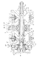
更に、本発明は、前述の図8〜9に示した様な従来から知られているダブルキャビティ型のトロイダル型無段変速機の様に、押圧装置9と予圧付与の為の皿板ばね41とを直列に配置した構造に限らず、図11に示す様に、押圧装置9と皿板ばね41とを並列に設けた構造(特願平10−202098号)を組み合わせる際にも利用できる。
【0038】
【発明の効果】
本発明のトロイダル型無段変速機用入力側ディスクユニットは、以上に述べた通り構成され作用する為、トロイダル型無段変速機の組立作業の能率化により、トロイダル型無段変速機の価格低減を図れる。又、構成各部品の強度を低下する事もない為、これら各部品の軽量化を十分に図る事も可能になる。
【図面の簡単な説明】
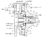
【図1】本発明の実施の形態の1例を示す端面図。
【図2】一部を省略して示す、図1のA−A断面図。
【図3】同B−B断面図。
【図4】従来から知られているトロイダル型無段変速機の基本的構成を、最大減速時の状態で示す側面図。
【図5】同じく最大増速時の状態で示す側面図。
【図6】従来の具体的構造の第1例を示す断面図。
【図7】図6のC−C断面図。
【図8】従来の具体的構造の第2例を示す部分断面図。
【図9】同第3例を示す部分断面図。
【図10】本発明に先立って考えたトロイダル型無段変速機用入力側ディスクユニットの断面図。
【図11】具体的構造の別例を示す部分断面図。
【符号の説明】
1 入力軸
2、2A、2B 入力側ディスク
2a 内側面
3 出力軸
4 出力側ディスク
4a 内側面
5 枢軸
6 トラニオン
7 変位軸
8 パワーローラ
8a 周面
9 押圧装置
10 カム板
11 保持器
12 ローラ
13 駆動側カム面
14 被駆動側カム面
15、15a、15b 入力軸
16 ニードル軸受
17、17a 鍔部
18、18a 出力歯車
19 キー
20 支持板
21 支持軸部
22 枢支軸部
23 円孔
24、25 ラジアルニードル軸受
26 スラスト玉軸受
27 スラストニードル軸受
28 保持器
29 玉
30 外輪
31 レース
32 保持器
33 ニードル
34 組み付け用治具
35 通孔
36 駆動ロッド
37 駆動ピストン
38 駆動シリンダ
39 ローディングナット
40、40a ボールスプライン
41 皿板ばね
42 スラストニードル軸受
43 アンギュラ型玉軸受
44 仕切壁
45 皿板ばね
46 内径側ボールスプライン溝
47 外径側ボールスプライン溝
48 ボール
49、49a 係止溝
50、50a 係止環
51 駆動軸
52 ラジアル軸受
53 ハウジング
54 通孔
55 ねじ孔
56 組み付け治具
57 基板
58 ねじ
59 抑え板
60 内輪軌道
61 外輪軌道
62 玉
63 玉軸受
64 ディスク側止め輪
65 軸側止め輪
66 小径部
67 基板
68 係合腕
69 押圧板
70 結合ねじ
71 結合ねじ
72 係止部
73 ねじ孔
74 押圧ねじ
75 結合部
76 押圧部
77 係止溝
78 結合部[0001]
BACKGROUND OF THE INVENTION
An input disk unit for a toroidal type continuously variable transmission according to the present invention is an assembly work for a toroidal type continuously variable transmission that is used, for example, as a transmission unit for an automobile transmission or as a transmission for various industrial machines. This is intended to improve the performance based on the accuracy improvement.
[0002]
[Prior art]
The use of a toroidal continuously variable transmission as schematically shown in FIGS. 4 to 5 has been studied as a transmission for automobiles. This toroidal continuously variable transmission, for example, as disclosed in Japanese Utility Model Laid-Open No. 62-71465, supports an
[0003]
That is, the
[0004]
A loading cam
[0005]
When the toroidal type continuously variable transmission configured as described above is used, when the
[0006]
When changing the rotational speed ratio (transmission ratio) between the
[0007]
6 to 7 show an example of a more specific toroidal type continuously variable transmission described in the microfilm of Japanese Utility Model Application No. 63-69293 (Japanese Utility Model Laid-Open No. 1-173352). The
[0008]
Both ends of the pair of
[0009]
The pair of
[0010]
Further, the
[0011]
Each of the
[0012]
Further, driving
[0013]
In the case of the toroidal type continuously variable transmission configured as described above, the rotation of the
[0014]
When the rotational force is transmitted between the
[0015]
Furthermore, in order to increase the torque that can be transmitted, two input side disks 2A and 2B and two
[0016]
However, one (the left side in FIGS. 8 to 9) of the input side disk 2A has a back surface (the left surface in FIGS. 8 to 9) on the
[0017]
In the case of the structural example shown in FIG. 8, the output side gear 18a is prevented from being displaced in the axial direction by a pair of
[0018]
The ball splines 40 and 40a installed for the above-described purposes are an inner diameter side ball spline groove 46 formed on the inner peripheral surface of the input side disk 2A and 2B and an outer surface formed on the outer peripheral surface of the intermediate portion of the
[0019]
[Problems to be solved by the invention]
Conventionally, when assembling the toroidal type continuously variable transmission constructed and operated as described above, the components are assembled in order inside the housing 53 (FIG. 7) that houses the main body of the toroidal type continuously variable transmission. I did it. Therefore, the positional relationship of each part based on the integration of the dimensional errors of the constituent parts, and whether or not the constituent parts function correctly, is determined after all the constituent parts are assembled in the
On the other hand, in order to ensure the efficiency and durability of the toroidal continuously variable transmission, the positional relationship between the constituent members must be maintained with high accuracy. For this reason, when the deviation of the positional relationship of each part becomes large based on the integration of the dimensional error of each component, it is assembled in the
If the assembly work of the toroidal type continuously variable transmission is performed in this way, the manufacturing work of the toroidal type continuously variable transmission is troublesome and the cost cannot be reduced.
[0020]
On the other hand, as shown in FIG. 10, through
[0021]
However, in the structure shown in FIG. 10, the strength of the
The input side disk unit for toroidal type continuously variable transmissions of the present invention has been invented in view of such circumstances.
[0022]
[Means for solving the problems]
The input side disk unit for a toroidal-type continuously variable transmission according to the present invention is supported on an input shaft, a flange fixed to one end of the input shaft, and an inner surface of the flange that is a side surface closer to the middle of the input shaft. An annular cam plate having a driving cam surface that is uneven on the inner surface in the circumferential direction, and a driven cam surface that is uneven on the outer surface facing the driving cam surface in the circumferential direction. In addition, the inner surface on the opposite side in the axial direction is a concave surface having a circular arc cross section, and the displacement in the axial direction relative to the input shaft and the rotation synchronized with the input shaft can be freely performed around the portion near the one end of the intermediate portion of the input shaft. A supported input-side disk, a plurality of rollers sandwiched between the driving-side cam surface and the driven-side cam surface, and a holder that holds the plurality of rollers in a freely rolling manner. Separate parts: input shaft, cam plate and input disk A roller and cage, before assembly to the toroidal type continuously variable transmission, the assembling jig in which bound to advance assembled non separated positional relationship after completion of assembly of the toroidal type continuously variable transmission.
The assembling jig constituting the input side disk unit for the toroidal type continuously variable transmission of the present invention has a plurality of engagements, each of which can be engaged with the outer peripheral edge portion of the inner side surface of the input side disk. The cam plate can be coupled to the base end portion of each engagement arm portion and the distal end portion of each engagement arm portion is engaged with the outer peripheral edge portion of the inner side surface of the input side disk. A substrate portion facing the outer side surface and a center portion of the substrate portion, the tip of each engaging arm portion being engaged with the outer peripheral edge portion of the inner side surface of the input side disk, the input shaft. A pressing portion facing the end surface.
[0023]
[Action]
The toroidal continuously variable transmission configured to include the input side disk unit for the toroidal continuously variable transmission of the present invention configured as described above is based on the same operation as the above-described conventional toroidal continuously variable transmission, Rotational force is transmitted between the input side disk and the output side disk, and the rotation speed ratio between these two disks is changed by changing the inclination angle of the trunnion.
[0024]
In particular, in the case of the input side disk unit for the toroidal type continuously variable transmission according to the present invention, the input shaft, the cam plate, the input side disk, the roller, and the cage, which are separate parts, are provided with the toroidal type continuously variable transmission. Prior to assembly to the machine, the assembly relationship of the toroidal continuously variable transmission is pre-assembled and non-separated by an assembly jig. For this reason, it is possible to confirm the deviation of the positional relationship between the respective parts based on the integration of dimensional errors of the constituent parts, and whether or not the constituent parts function correctly before assembling the constituent parts in the housing. Therefore, the positional relationship between the constituent members is increased in order to ensure the efficiency and durability of the toroidal continuously variable transmission without requiring troublesome work such as disassembling and reassembling the entire toroidal continuously variable transmission. The accuracy can be maintained. Moreover, the assembling jig can assemble the input shaft, the cam plate, the input side disk, the roller, and the cage without forming a through hole or a screw hole in any of these parts. For this reason, it is not necessary to reduce the strength of any of the above components based on the mounting of the assembly jig.
[0025]
DETAILED DESCRIPTION OF THE INVENTION
1 to 3 show an example of an embodiment of the present invention. The feature of the present invention is that a structure in which the input side disk 2A, the
[0026]
A
[0027]
The input side disk 2A is supported via a
[0028]
A
[0029]
Also, a loading cam
[0030]
In the case of the input side disk unit for the toroidal type continuously variable transmission according to the present invention, the
[0031]
First, the shaft
[0032]
If a predetermined number of
[0033]
The
[0034]
Further, the
[0035]
On the other hand, if the dimensions and operation states of the respective parts described above are inappropriate, the
[0036]
Note that the output side disk unit and the power roller unit also check the dimensions and operating states of each part after assembling a plurality of parts and before assembling in the housing in the same manner as the input side disk unit described above. If the operating state is appropriate, the above parts are temporarily fixed with an appropriate jig. Therefore, in a state where the above units are combined to form a toroidal continuously variable transmission, the operating state of each component can be made appropriate. It should be noted that rust preventive oil is adhered to the surface of each part constituting each unit, and this rust preventive oil is also used when mixed in the traction oil filled in the toroidal type continuously variable transmission. It is preferable to use a designated rust preventive oil that does not easily deteriorate the traction oil.
[0037]
Further, the present invention is similar to the conventional double cavity type toroidal continuously variable transmission as shown in FIGS. 8 to 9 described above. As shown in FIG. 11, the present invention can be used when combining a structure (Japanese Patent Application No. 10-202098) in which the
[0038]
【The invention's effect】
Since the input side disk unit for the toroidal continuously variable transmission according to the present invention is configured and operates as described above, the cost of the toroidal continuously variable transmission is reduced by improving the efficiency of the assembly work of the toroidal continuously variable transmission. Can be planned. Further, since the strength of each component is not lowered, it is possible to sufficiently reduce the weight of each component.
[Brief description of the drawings]
FIG. 1 is an end view showing an example of an embodiment of the present invention.
FIG. 2 is a cross-sectional view taken along the line AA in FIG.
FIG. 3 is a sectional view taken along the line BB in FIG.
FIG. 4 is a side view showing a basic configuration of a conventionally known toroidal type continuously variable transmission in a state of maximum deceleration.
FIG. 5 is a side view showing the state of the maximum speed increase.
FIG. 6 is a cross-sectional view showing a first example of a conventional concrete structure.
7 is a cross-sectional view taken along the line CC of FIG.
FIG. 8 is a partial cross-sectional view showing a second example of a conventional concrete structure.
FIG. 9 is a partial sectional view showing the third example.
FIG. 10 is a cross-sectional view of an input side disk unit for a toroidal-type continuously variable transmission that was considered prior to the present invention.
FIG. 11 is a partial cross-sectional view showing another example of a specific structure.
[Explanation of symbols]
1 Input shaft
2, 2A, 2B input disk
2a inner surface
3 Output shaft
4 Output disk
4a inner surface
5 Axis
6 Trunnion
7 Displacement axis
8 Power roller
8a circumference
9 Pressing device
10 Cam plate
11 Cage
12 Laura
13 Drive side cam surface
14 Driven cam surface
15, 15a, 15b Input shaft
16 Needle bearing
17, 17a buttock
18, 18a Output gear
19 keys
20 Support plate
21 Support shaft
22 Pivot shaft
23 hole
24, 25 Radial needle bearing
26 Thrust ball bearing
27 Thrust Needle Bearing
28 Cage
29 balls
30 Outer ring
31 races
32 Cage
33 Needle
34 Jig for assembly
35 through holes
36 Drive rod
37 Drive piston
38 Drive cylinder
39 Loading nut
40, 40a Ball spline
41 Disc leaf spring
42 Thrust needle bearing
43 Angular type ball bearings
44 partition wall
45 Disc leaf spring
46 Inner side ball spline groove
47 Outer diameter side ball spline groove
48 balls
49, 49a Locking groove
50, 50a Locking ring
51 Drive shaft
52 Radial bearings
53 Housing
54 through holes
55 Screw hole
56 Assembly jig
57 substrates
58 screw
59 Retaining plate
60 Inner ring raceway
61 Outer ring raceway
62 balls
63 Ball bearing
64 disc side retaining ring
65 Shaft side retaining ring
66 Small diameter part
67 substrates
68 engaging arms
69 Press plate
70 coupling screw
71 coupling screw
72 Locking part
73 Screw hole
74 Press screw
75 joints
76 Pressing part
77 Locking groove
78 joints
Claims (1)
Priority Applications (1)
| Application Number | Priority Date | Filing Date | Title |
|---|---|---|---|
| JP36910198A JP3829512B2 (en) | 1998-12-25 | 1998-12-25 | Input side disk unit for toroidal type continuously variable transmission |
Applications Claiming Priority (1)
| Application Number | Priority Date | Filing Date | Title |
|---|---|---|---|
| JP36910198A JP3829512B2 (en) | 1998-12-25 | 1998-12-25 | Input side disk unit for toroidal type continuously variable transmission |
Publications (3)
| Publication Number | Publication Date |
|---|---|
| JP2000193056A JP2000193056A (en) | 2000-07-14 |
| JP2000193056A5 JP2000193056A5 (en) | 2005-07-21 |
| JP3829512B2 true JP3829512B2 (en) | 2006-10-04 |
Family
ID=18493568
Family Applications (1)
| Application Number | Title | Priority Date | Filing Date |
|---|---|---|---|
| JP36910198A Expired - Fee Related JP3829512B2 (en) | 1998-12-25 | 1998-12-25 | Input side disk unit for toroidal type continuously variable transmission |
Country Status (1)
| Country | Link |
|---|---|
| JP (1) | JP3829512B2 (en) |
Families Citing this family (4)
| Publication number | Priority date | Publication date | Assignee | Title |
|---|---|---|---|---|
| JP2005320992A (en) * | 2004-05-06 | 2005-11-17 | Nsk Ltd | Assembling method and assembling tool of toroidal type continuously variable transmission |
| JP4771117B2 (en) * | 2005-06-07 | 2011-09-14 | 日本精工株式会社 | Toroidal continuously variable transmission |
| JP4735970B2 (en) * | 2005-12-16 | 2011-07-27 | 日本精工株式会社 | Assembly assembly of toroidal type continuously variable transmission and fixture for assembly assembly |
| JP6221665B2 (en) * | 2013-11-14 | 2017-11-01 | 日本精工株式会社 | Toroidal continuously variable transmission |
-
1998
- 1998-12-25 JP JP36910198A patent/JP3829512B2/en not_active Expired - Fee Related
Also Published As
| Publication number | Publication date |
|---|---|
| JP2000193056A (en) | 2000-07-14 |
Similar Documents
| Publication | Publication Date | Title |
|---|---|---|
| JP3829512B2 (en) | Input side disk unit for toroidal type continuously variable transmission | |
| JPH08135747A (en) | Toroidal type continuously variable transmission | |
| US6375595B1 (en) | Toroidal type continuously variable transmission | |
| JP3740812B2 (en) | Output side disk unit for toroidal type continuously variable transmission | |
| JP3750294B2 (en) | Toroidal-type continuously variable transmission and its assembly method | |
| JP3424560B2 (en) | Input disk unit for toroidal type continuously variable transmission | |
| JP3783626B2 (en) | Toroidal continuously variable transmission | |
| JP3666216B2 (en) | Toroidal type continuously variable transmission assembly method | |
| JP4182593B2 (en) | Input side disk unit for toroidal type continuously variable transmission | |
| JP4206724B2 (en) | Toroidal type continuously variable transmission assembly method | |
| JP4362858B2 (en) | Ball spline of toroidal type continuously variable transmission | |
| JP4078752B2 (en) | Toroidal continuously variable transmission | |
| JP3480034B2 (en) | Toroidal type continuously variable transmission | |
| JP4019549B2 (en) | Toroidal continuously variable transmission | |
| JP3617235B2 (en) | Toroidal continuously variable transmission | |
| JP4032547B2 (en) | Toroidal type continuously variable transmission assembly method | |
| JP3899761B2 (en) | Toroidal continuously variable transmission | |
| JP4032549B2 (en) | Toroidal continuously variable transmission | |
| JPH10339361A (en) | Toroidal type continuously variable transmission | |
| JP2576535Y2 (en) | Disc for toroidal type continuously variable transmission | |
| JP3617265B2 (en) | Toroidal continuously variable transmission | |
| JP2000283255A (en) | Loading cam device for troidal continuously variable transmission and thrust measuring device thereof and assembly method for troidal continuously variable transmission | |
| JPH0814350A (en) | Toroidal-type continuously variable transmission | |
| JP2576534Y2 (en) | Toroidal type continuously variable transmission | |
| JP2000220712A (en) | Toroidal type continuously variable transmission |
Legal Events
| Date | Code | Title | Description |
|---|---|---|---|
| A521 | Written amendment |
Free format text: JAPANESE INTERMEDIATE CODE: A523 Effective date: 20041209 |
|
| A621 | Written request for application examination |
Free format text: JAPANESE INTERMEDIATE CODE: A621 Effective date: 20041209 |
|
| A977 | Report on retrieval |
Free format text: JAPANESE INTERMEDIATE CODE: A971007 Effective date: 20060608 |
|
| TRDD | Decision of grant or rejection written | ||
| A01 | Written decision to grant a patent or to grant a registration (utility model) |
Free format text: JAPANESE INTERMEDIATE CODE: A01 Effective date: 20060620 |
|
| A61 | First payment of annual fees (during grant procedure) |
Free format text: JAPANESE INTERMEDIATE CODE: A61 Effective date: 20060703 |
|
| R150 | Certificate of patent or registration of utility model |
Free format text: JAPANESE INTERMEDIATE CODE: R150 |
|
| FPAY | Renewal fee payment (event date is renewal date of database) |
Free format text: PAYMENT UNTIL: 20100721 Year of fee payment: 4 |
|
| FPAY | Renewal fee payment (event date is renewal date of database) |
Free format text: PAYMENT UNTIL: 20110721 Year of fee payment: 5 |
|
| FPAY | Renewal fee payment (event date is renewal date of database) |
Free format text: PAYMENT UNTIL: 20110721 Year of fee payment: 5 |
|
| FPAY | Renewal fee payment (event date is renewal date of database) |
Free format text: PAYMENT UNTIL: 20120721 Year of fee payment: 6 |
|
| FPAY | Renewal fee payment (event date is renewal date of database) |
Free format text: PAYMENT UNTIL: 20120721 Year of fee payment: 6 |
|
| FPAY | Renewal fee payment (event date is renewal date of database) |
Free format text: PAYMENT UNTIL: 20130721 Year of fee payment: 7 |
|
| LAPS | Cancellation because of no payment of annual fees |