JP3825427B2 - Pattern color control method for printing machine and printing machine - Google Patents
Pattern color control method for printing machine and printing machine Download PDFInfo
- Publication number
- JP3825427B2 JP3825427B2 JP2003288582A JP2003288582A JP3825427B2 JP 3825427 B2 JP3825427 B2 JP 3825427B2 JP 2003288582 A JP2003288582 A JP 2003288582A JP 2003288582 A JP2003288582 A JP 2003288582A JP 3825427 B2 JP3825427 B2 JP 3825427B2
- Authority
- JP
- Japan
- Prior art keywords
- color
- target
- halftone
- density
- halftone density
- Prior art date
- Legal status (The legal status is an assumption and is not a legal conclusion. Google has not performed a legal analysis and makes no representation as to the accuracy of the status listed.)
- Expired - Lifetime
Links
- 238000000034 method Methods 0.000 title claims description 75
- 238000006243 chemical reaction Methods 0.000 claims description 45
- 239000000203 mixture Substances 0.000 claims description 45
- 239000007787 solid Substances 0.000 claims description 37
- 230000035945 sensitivity Effects 0.000 claims description 14
- 239000003086 colorant Substances 0.000 claims description 7
- 235000000177 Indigofera tinctoria Nutrition 0.000 claims description 6
- 229940097275 indigo Drugs 0.000 claims description 6
- COHYTHOBJLSHDF-UHFFFAOYSA-N indigo powder Natural products N1C2=CC=CC=C2C(=O)C1=C1C(=O)C2=CC=CC=C2N1 COHYTHOBJLSHDF-UHFFFAOYSA-N 0.000 claims description 6
- 238000013459 approach Methods 0.000 claims 2
- 230000003247 decreasing effect Effects 0.000 claims 2
- 102100026064 Exosome complex component RRP43 Human genes 0.000 claims 1
- 101001055989 Homo sapiens Exosome complex component RRP43 Proteins 0.000 claims 1
- 235000021419 vinegar Nutrition 0.000 claims 1
- 239000000052 vinegar Substances 0.000 claims 1
- 238000012545 processing Methods 0.000 description 19
- 238000004364 calculation method Methods 0.000 description 18
- 238000013461 design Methods 0.000 description 9
- 238000005259 measurement Methods 0.000 description 8
- 230000003595 spectral effect Effects 0.000 description 6
- 238000012937 correction Methods 0.000 description 4
- 238000011161 development Methods 0.000 description 4
- 238000010586 diagram Methods 0.000 description 4
- 239000010408 film Substances 0.000 description 4
- 239000010893 paper waste Substances 0.000 description 3
- 238000006073 displacement reaction Methods 0.000 description 2
- 238000003672 processing method Methods 0.000 description 2
- 230000002159 abnormal effect Effects 0.000 description 1
- 239000000470 constituent Substances 0.000 description 1
- 238000007796 conventional method Methods 0.000 description 1
- 238000005286 illumination Methods 0.000 description 1
- 238000007689 inspection Methods 0.000 description 1
- 230000010354 integration Effects 0.000 description 1
- 238000004519 manufacturing process Methods 0.000 description 1
- 230000035484 reaction time Effects 0.000 description 1
- 238000012360 testing method Methods 0.000 description 1
- 239000010409 thin film Substances 0.000 description 1
- 238000011144 upstream manufacturing Methods 0.000 description 1
- 239000002699 waste material Substances 0.000 description 1
Images


Description
本発明は、印刷機の絵柄色調制御方法及び印刷機に関し、特に、IRGB濃度計を用いて色調を制御する絵柄色調制御方法及びその絵柄色調制御を備えた印刷機に関する。 The present invention relates to a design color tone control method for a printing press and a printing press , and more particularly to a design color tone control method for controlling color tone using an IRGB densitometer and a printing press equipped with the design color tone control .
従来行われていた印刷機の絵柄の色調制御の方法として、絵柄とともに印刷シートの余白部分に色調検査用のカラーパッチを印刷し、このカラーパッチの分光反射率を分光計にて測定して、その測定結果から絵柄の色調の目標とする色調からのずれを検出して各色のインキ供給量を制御する方法がある。しかしながら、この方法では、印刷シートにカラーパッチを印刷するための余白が必要なため、余白の分だけ紙を無駄にしてしまう。 As a conventional method of controlling the color tone of the pattern of a printing press, a color patch for color tone inspection is printed on the margin of the print sheet together with the pattern, and the spectral reflectance of this color patch is measured with a spectrometer. There is a method of controlling the ink supply amount of each color by detecting a deviation from the target color tone of the pattern from the measurement result. However, this method requires a margin for printing the color patch on the print sheet, and thus wastes paper for the margin.
この問題に対し特許文献1及び特許文献2には、カラーパッチを用いることなく、絵柄自体の絵柄の色調制御を行う方法が提案されている。これらの文献に開示された方法は、要約すると次のような手順となる。
まず、各色の印刷ユニットで印刷された絵柄の分光反射率を分光計にて測定する。そして、インキキーのキーゾーン毎に分光反射率(キーゾーン全体の平均分光反射率)を演算し、さらに各キーゾーンの分光反射率を国際照明委員会が提唱する色座標値(L*a*b*)に変換する。各色のインキ供給量を調整して試印刷を行い、所望の色調を有する印刷シート(以下、OKシートという)が得られたら、OKシートの各キーゾーンの色座標値を目標色座標値に設定する。次に、本印刷を開始してキーゾーン毎にOKシートと印刷シート(以下、本印刷で得られた印刷シートを本刷りシートという)との色座標値の差(色差)を算出し、色差に対する各印刷ユニットのインキキーの開度の増減量を計算して、色差がゼロになるように各印刷ユニットの各インキキーの開度をオンライン制御によって調整する。
First, the spectral reflectance of the pattern printed by each color printing unit is measured with a spectrometer. Then, the spectral reflectance (average spectral reflectance of the entire key zone) is calculated for each key zone of the ink key, and the color coordinate value (L * a * b) proposed by the International Illumination Committee for the spectral reflectance of each key zone. * Convert to). Test printing is performed by adjusting the ink supply amount of each color, and when a print sheet having a desired color tone (hereinafter referred to as “OK sheet”) is obtained, the color coordinate value of each key zone of the OK sheet is set as the target color coordinate value. To do. Next, the actual printing is started, and the color coordinate value difference (color difference) between the OK sheet and the printing sheet (hereinafter, the printing sheet obtained by the main printing is referred to as the main printing sheet) is calculated for each key zone. The amount of increase / decrease in the ink key opening of each printing unit with respect to is calculated, and the opening of each ink key in each printing unit is adjusted by online control so that the color difference becomes zero.
しかしながら、上記特許文献1,2に開示された方法には、以下のような課題がある。まず、上記方法では、計測手段として分光計を用いているが、分光計はコストが高く、さらに、分光計は新聞用輪転機のように計測対象(この場合は印刷シート)が極めて高速で移動する場合には処理能力上追従することができない。また、上記方法では、OKシートが印刷されてから色調制御が開始されることになるため、立ち上がりからOKシートが印刷されるまでの間に多くの損紙が発生してしまう。また、上記方法では、インキキーのキーゾーン内の絵柄をキーゾーン全体で平均化してその平均分光反射率に基づいて色調制御を行うため、キーゾーン内の絵柄の画線率が低い場合には、分光計の計測誤差が大きくなり、制御が不安定になりやすい。さらに、客先からの注文には、絵柄中の特定の注目点について特に厳しい色調管理を要求される場合があるが、このように特定の注目点について色調制御したい場合には、基準となる画像データとして上流の製版工程からCIP3〔CIP3(Cooperation for Integration of Prepress, Press, Postpress)規格のPPF(Print Production Format)〕等のデータをもらわなければならない。
However, the methods disclosed in
本発明は、上述の課題に鑑み創案されたもので、分光計よりもコストが低いIRGB濃度計を用いて色調制御を行えるようにした、印刷機の絵柄色調制御方法を提供することを第1の目的とする。
また、本発明は、OKシートが得られる以前の印刷開始直後から色調制御を行えるようにした、印刷機の絵柄色調制御方法を提供することを第2の目的とする。
The present invention was devised in view of the above-described problems. It is a first object of the present invention to provide a picture color tone control method for a printing press that enables color tone control using an IRGB densitometer that is less expensive than a spectrometer. The purpose.
A second object of the present invention is to provide a picture color tone control method for a printing press that enables color tone control immediately after the start of printing before an OK sheet is obtained.
また、本発明は、インキ供給単位幅毎に絵柄の色調制御を行う場合に、インキ供給単位幅内の絵柄の画線率が低くても、センサの計測誤差が少なく、安定した色調制御を行えるようにした、印刷機の絵柄色調制御方法を提供することを第3の目的とする。
さらに、本発明は、基準となる画像データを必要とせず、絵柄の特定の注目点について色調制御を行えるようにした、印刷機の絵柄色調制御方法を提供することを第4の目的とする。
Further, according to the present invention, when color tone control of a pattern is performed for each ink supply unit width, even if the line drawing rate of the pattern within the ink supply unit width is low, the measurement error of the sensor is small and stable color tone control can be performed. A third object is to provide a design color tone control method for a printing press.
Furthermore, a fourth object of the present invention is to provide a picture color tone control method for a printing press that does not require image data as a reference and can perform color tone control for a specific attention point of the picture.
さらに、本発明は、基準となる画像データ(PPFデータ等の絵柄面積率データ)を得られる場合に、これを有効に活用して正確な色調制御を行えるようにした、印刷機の絵柄色調制御方法を提供することを第5の目的とする。 Further, according to the present invention, when image data serving as a reference (pattern area ratio data such as PPF data) can be obtained, the pattern color tone control of a printing press can be performed effectively by using this data effectively. A fifth object is to provide a method.
上記の目的を達成するために、本発明の印刷機の絵柄色調制御方法では、まず、印刷絵柄をインキ供給装置のインキ供給単位幅で分割したときのインキ供給単位幅毎の目標混色網濃度を設定する。インキ供給装置のインキ供給単位幅とは、インキ供給装置がインキキー装置である場合には各インキキーのキー幅(キーゾーン)のことであり、インキ供給装置がデジタルポンプ装置である場合には各デジタルポンプのポンプ幅のことである。なお、目標混色網濃度の設定方法は、後述するように種々の方法があり、状況に応じた適宜の方法を用いる。 In order to achieve the above object, in the picture color tone control method of the printing machine of the present invention, first, the target mixed color halftone density for each ink supply unit width when the printed picture is divided by the ink supply unit width of the ink supply device is obtained. Set. The ink supply unit width of the ink supply device is the key width (key zone) of each ink key when the ink supply device is an ink key device, and each digital when the ink supply device is a digital pump device. It is the pump width of the pump. There are various methods for setting the target color mixture halftone density as will be described later, and an appropriate method according to the situation is used.
印刷を開始して本刷りシートが得られると、IRGB濃度計を用いて本刷りシートのインキ供給単位幅毎の実混色網濃度を計測する。そして、予め設定した各インキ色の網点面積率と混色網濃度との対応関係に基づき、実混色網濃度に対応する各インキ色の実網点面積率を求める。実網点面積率を実混色網濃度から求める方法としては、各インキ色の網点面積率と混色網濃度との関係を記憶したデータベース、例えば、ISO/TC130国内委員会が制定した新聞印刷JapanColor基準の印刷物を印刷し、IRGB濃度計で実測したデータベースを用いてもよく、より簡単には、そのデータベースを利用して公知のノイゲバウアーの式で近似した値を利用することもできる。また、上記の網点面積率と混色網濃度との対応関係に基づき、目標混色網濃度に対応する各インキ色の目標網点面積率も求めておく。目標網点面積率については、実網点面積率のように毎回求める必要はなく、目標混色網濃度が変わらない限りは一度求めておけばよい。例えば、目標混色網濃度を設定した時点で目標網点面積率も求めておいてもよい。 When printing is started and a main printing sheet is obtained, an actual color mixture halftone density for each ink supply unit width of the main printing sheet is measured using an IRGB densitometer. Then, the actual halftone dot area ratio of each ink color corresponding to the actual mixed color halftone density is obtained based on the correspondence relationship between the halftone dot area ratio of each ink color and the mixed color halftone density. As a method for obtaining the actual halftone dot area ratio from the actual mixed color halftone density, a database storing the relationship between the halftone dot area ratio of each ink color and the mixed color halftone density, for example, newspaper printing JapanColor established by the ISO / TC130 National Committee. A database obtained by printing a standard printed matter and actually measured by an IRGB densitometer may be used. More simply, a value approximated by a well-known Neugebauer equation can be used by using the database. Further, based on the correspondence between the halftone dot area ratio and the mixed color halftone density, the target halftone dot area ratio of each ink color corresponding to the target mixed color halftone density is also obtained. The target halftone dot area ratio does not need to be obtained every time as the actual halftone dot area ratio, and may be obtained once as long as the target mixed color halftone density does not change. For example, the target dot area ratio may also be obtained when the target color mixture halftone density is set.
次に、予め設定した網点面積率と単色網濃度との対応関係に基づき、実網点面積率に対応する実単色網濃度を求める。実単色網濃度を実網点面積率から求める方法としては、単色網濃度と網点面積率との関係を表すマップやテーブルを用意しておき、これらのマップやテーブルに実網点面積率を当てはめるようにすればよい。また、上記の網点面積率と単色網濃度との対応関係に基づき、目標網点面積率に対応する目標単色網濃度も求めておく。目標単色網濃度については、実単色網濃度のように毎回求める必要はなく、目標網点面積率が変わらない限りは一度求めておけばよい。例えば、目標網点面積率を設定した時点で目標単色網濃度も求めておいてもよい。 Next, an actual monochrome halftone density corresponding to the actual halftone dot area ratio is obtained based on a correspondence relationship between a preset halftone dot area ratio and the monochrome halftone density. As a method of obtaining the actual monochrome dot density from the actual dot area ratio, a map or table showing the relationship between the monochrome dot density and the dot area ratio is prepared, and the actual dot area ratio is set in these maps or tables. Just apply. Further, based on the correspondence relationship between the halftone dot area ratio and the monochrome halftone density, a target monochrome halftone density corresponding to the target halftone dot area ratio is also obtained. The target monochromatic halftone density need not be obtained every time as in the case of the actual monochromatic halftone density, and may be obtained once as long as the target halftone dot area ratio does not change. For example, the target monochromatic halftone density may also be obtained when the target halftone dot area ratio is set.
次に、予め設定した網点面積率と単色網濃度とベタ濃度との対応関係に基づき、目標網点面積率のもとでの目標単色網濃度と実単色網濃度との偏差に対応するベタ濃度偏差を求める。ベタ濃度偏差を求める方法としては、上記体対応関係を表すマップやテーブルを用意しておき、これらのマップやテーブルに目標網点面積率,目標単色網濃度及び実単色網濃度を当てはめてもよく、より簡単には、公知のユールニールセンの式を用いて前記関係を近似して、それを利用して求めてもよい。そして、求めたベタ濃度偏差に基づきインキ供給単位幅毎にインキ供給量を調整し、各色のインキの供給量をインキ供給単位幅毎に制御する。ベタ濃度偏差に基づくインキ供給量の調整量は、簡単には、後の実施形態にて詳述する公知のAPI(オートプリセットインキング)関数を用いて求めることができる。 Next, based on the correspondence relationship between the halftone dot area ratio, the monochrome halftone density, and the solid density set in advance, the solid color corresponding to the deviation between the target monochrome halftone density and the actual monochrome halftone density under the target halftone dot area ratio. Obtain the concentration deviation. As a method for calculating the solid density deviation, a map or table showing the above-mentioned body correspondence may be prepared, and the target halftone dot area ratio, the target monochromatic halftone density, and the actual monochromatic halftone density may be applied to these maps and tables. More simply, the relationship may be approximated using a well-known Yule-Nielsen equation and obtained using this equation. Then, the ink supply amount is adjusted for each ink supply unit width based on the obtained solid density deviation, and the ink supply amount for each color is controlled for each ink supply unit width. The adjustment amount of the ink supply amount based on the solid density deviation can be easily obtained by using a known API (Auto Preset Inking) function described in detail in a later embodiment.
このように、本発明の印刷機の絵柄色調制御方法によれば、分光計ではなくIRGB濃度計を用いて色調制御を行うことができるので、計測手段にかかるコストが低減できるとともに新聞輪転機のような高速印刷機にも十分に対応することが可能である。
なお、上記の絵柄色調制御方法は、以下の構成の絵柄色調制御装置によって実施することができる。本発明の印刷機の絵柄色調制御装置は、印刷幅方向に分割された領域毎にインキを供給するインキ供給装置、及び印刷で得られる本刷りシートの走行ライン上に配置されたIRGB濃度計(好ましくはラインセンサ型IRGB濃度計)に加え、目標混色網濃度設定手段、混色網濃度計測手段、目標網点面積率演算手段、実網点面積率演算手段、目標単色網濃度演算手段、実単色網濃度演算手段、ベタ濃度偏差演算手段、及びインキ供給量調整手段をその構成要素として備えている。
Thus, according to the picture color tone control method of the printing press of the present invention, since the color tone control can be performed using the IRGB densitometer instead of the spectrometer, the cost for the measuring means can be reduced and the newspaper rotary press can be controlled. Such a high-speed printing machine can be sufficiently accommodated.
The pattern color tone control method described above can be implemented by a pattern color tone control apparatus having the following configuration. The pattern color tone control device for a printing press according to the present invention includes an ink supply device that supplies ink for each region divided in the printing width direction, and an IRGB densitometer (on an IRGB densitometer disposed on a running line of a main printing sheet obtained by printing). (Preferably a line sensor type IRGB densitometer), target mixed color halftone density setting means, mixed color halftone density measuring means, target halftone dot area ratio calculating means, real halftone dot area ratio calculating means, target single color halftone density calculating means, actual single color A halftone density calculating means, a solid density deviation calculating means, and an ink supply amount adjusting means are provided as constituent elements.
このうち、目標混色網濃度設定手段、混色網濃度計測手段、目標網点面積率演算手段、実網点面積率演算手段、目標単色網濃度演算手段、実単色網濃度演算手段、ベタ濃度偏差演算手段、及びインキ供給量調整手段は、プログラムされたコンピュータの一機能として実現することができる。これらの各機能について説明すると、まず、目標混色網濃度設定手段は、印刷絵柄をインキ供給装置のインキ供給単位幅で分割したときのインキ供給単位幅毎の目標混色網濃度を設定する機能を有している。混色網濃度計測手段は、IRGB濃度計を利用して本刷りシートのインキ供給単位幅毎の実混色網濃度を計測する機能を有している。目標網点面積率演算手段は、予め設定した各インキ色の網点面積率と混色網濃度との対応関係(例えばノイゲバウアーの式)に基づき、目標混色網濃度に対応する各インキ色の目標網点面積率を求める機能を有し、実網点面積率演算手段は、同じ対応関係に基づき実混色網濃度に対応する各インキ色の実網点面積率を求める機能を有している。目標単色網濃度演算手段は、予め設定した網点面積率と単色網濃度との対応関係に基づき、目標網点面積率に対応する目標単色網濃度を求める機能を有し、実単色網濃度演算手段は、同じ対応関係に基づき、実網点面積率に対応する実単色網濃度を求める機能を有している。ベタ濃度偏差演算手段は、予め設定した網点面積率と単色網濃度とベタ濃度との対応関係(例えばユールニールセンの式)に基づき、目標網点面積率のもとでの目標単色網濃度と実単色網濃度との偏差に対応するベタ濃度偏差を求める機能を有している。そして、インキ供給量調整手段は、ベタ濃度偏差に基づき、例えばAPI関数によりインキ供給単位幅毎にインキ供給装置のインキ供給量を調整する機能を有している。なお、好ましくは、IRGB濃度計における網点面積率と混色網濃度と色座標値との対応関係を規定した変換テーブルを備え、目標網点面積率演算手段及び実網点面積率演算手段は、この変換テーブルを用いて目標網点面積率或いは実網点面積率を求めるように構成する。 Among these, target mixed color halftone density setting means, mixed color halftone density measuring means, target halftone dot area ratio calculating means, actual halftone dot area ratio calculating means, target single color halftone density calculating means, actual single color halftone density calculating means, solid density deviation calculating The means and the ink supply amount adjusting means can be realized as one function of a programmed computer. Each of these functions will be described. First, the target color mixture halftone density setting unit has a function of setting a target color mixture halftone density for each ink supply unit width when the printed pattern is divided by the ink supply unit width of the ink supply device. is doing. The mixed color halftone density measuring means has a function of measuring the actual mixed color halftone density for each ink supply unit width of the main printing sheet using an IRGB densitometer. The target halftone dot area ratio calculating means is configured to set a target halftone dot area corresponding to the target mixed color halftone density based on a correspondence relationship between the halftone dot area ratio of each ink color and the mixed color halftone density (for example, Neugebauer equation). The actual dot area ratio calculating means has a function of determining the actual dot area ratio of each ink color corresponding to the actual mixed color halftone density based on the same correspondence. The target monochromatic halftone density calculation means has a function for obtaining a target monochromatic halftone density corresponding to the target halftone dot area ratio based on a correspondence relationship between a predetermined halftone dot area ratio and the monochromatic halftone density, and calculates an actual monochromatic halftone density. The means has a function of obtaining an actual monochromatic halftone density corresponding to the actual halftone dot area ratio based on the same correspondence. The solid density deviation calculating means calculates the target monochrome area density based on the target halftone dot area ratio based on a correspondence relationship between the halftone dot area ratio, the monochrome halftone density, and the solid density (for example, the Yule-Nielsen equation). It has a function for obtaining a solid density deviation corresponding to the deviation from the actual single color halftone density. The ink supply amount adjusting means has a function of adjusting the ink supply amount of the ink supply device for each ink supply unit width based on, for example, an API function based on the solid density deviation. Preferably, a conversion table that defines the correspondence between halftone dot area ratio, mixed color halftone density and color coordinate value in the IRGB densitometer, and the target halftone dot area ratio calculating means and the actual halftone dot area ratio calculating means, A target halftone dot area ratio or an actual halftone dot area ratio is obtained using this conversion table.
目標混色網濃度を設定する方法の一つとして、印刷開始からOKシートが得られるまでの間は、上記の各インキ色の網点面積率と混色網濃度との対応関係に基づき、今回の印刷絵柄における各インキ色のインキ供給単位幅毎の画線率に対応する混色網濃度を求め、上記画線率に対応する混色網濃度を目標混色網濃度として設定する。これにより、立ち上がり直後から色調制御を行うことができ、OKシートが得られるまでの時間を短縮して損紙を低減することが可能になる。インキ供給単位幅毎の画線率は予め製版工程で製作したフィルムをフィルムスキャナで測定或いは刷版をプレートスキャナで測定した値を用いるが、同じ画線率の印刷絵柄であっても、ドットゲイン(網点の面積の太り)を考慮すると印刷絵柄を構成する網の密度(50%平網,80%平網,ベタ等)により計測する濃度は異なってくるので、好ましくは、画線率に対応する混色網濃度を求めるに際し、網の密度に応じてドットゲインを考慮した補正を行うようにする。 As one method of setting the target color mixture halftone density, from the start of printing until an OK sheet is obtained, the current printing is based on the correspondence between the halftone dot area ratio of each ink color and the color mixture halftone density. The mixed color halftone density corresponding to the image line ratio for each ink supply unit width of each ink color in the pattern is obtained, and the mixed color halftone density corresponding to the image line ratio is set as the target mixed color halftone density. As a result, color tone control can be performed immediately after the start-up, and it is possible to shorten the time until an OK sheet is obtained and reduce waste paper. The line drawing rate for each ink supply unit width is a value obtained by measuring a film manufactured in advance in the plate making process with a film scanner or a plate plate with a plate scanner. Considering (thickness of halftone dot area), the density to be measured varies depending on the density of the mesh (50% flat mesh, 80% flat mesh, solid, etc.) constituting the printed pattern. When the corresponding mixed color halftone density is obtained, correction considering the dot gain is performed according to the density of the halftone.
一方、印刷品質を満たしたOKシートが得られた場合には、印刷物の低画線部あるいは人間の目に目立つ絵柄位置の色調制御性能を向上させるためOKシートの絵柄を構成する画素の中からインキ供給単位幅毎に各インキ色に対応する注目画素をそれぞれ設定して、注目画素の混色網濃度を目標混色網濃度として設定するのが好ましい。この場合、実混色網濃度を計測するステップでは、注目画素の実混色網濃度を計測する。これによれば、通常画素面積率データがない場合、画素の単色ベタ濃度推定は不可能であるが本方法ではそれを可能にし、インキ供給単位幅毎の画線率の情報があれば、絵柄の特定の注目点についても色調制御を行うことができる。また、計測値をインキ供給単位幅全体で平均化しないので、インキ供給単位幅内の絵柄の画線率が低くても(例えば、1ポイントのコーポレートカラーのような絵柄でも)、センサ(IRBG濃度計)の計測誤差が少なく、安定した色調制御を行うことができる。なお、ここでいう注目画素とは、一画素でもよく、連続する一塊の複数画素でもよい。複数画素の場合には、その目標混色網濃度及び実混色網濃度は、これら複数画素の平均混色網濃度の目標値或いは実測値となる。 On the other hand, when an OK sheet satisfying the print quality is obtained, it is selected from among the pixels constituting the pattern of the OK sheet in order to improve the color tone control performance of the low image portion of the printed matter or the pattern position conspicuous to human eyes. It is preferable to set the target pixel corresponding to each ink color for each ink supply unit width and set the mixed color halftone density of the target pixel as the target mixed color halftone density. In this case, in the step of measuring the actual mixed color halftone density, the actual mixed color halftone density of the target pixel is measured. According to this, when there is no normal pixel area ratio data, it is impossible to estimate the monochrome solid density of the pixel, but this method makes it possible, and if there is information on the line rate for each ink supply unit width, The tone control can also be performed for the specific attention point. In addition, since the measured values are not averaged over the entire ink supply unit width, the sensor (IRBG density) can be used even if the line drawing rate of the pattern within the ink supply unit width is low (for example, a pattern such as a one-point corporate color). Therefore, stable color tone control can be performed. Note that the pixel of interest referred to here may be a single pixel or a group of continuous pixels. In the case of a plurality of pixels, the target color mixture halftone density and the actual color mixture halftone density are the target value or the actual measurement value of the average color mixture halftone density of these pixels.
このように本発明の色調制御方法は、基準となる画像データがない場合でも注目画素毎の色調制御が可能であるが、外部(例えば、印刷依頼元等)から印刷対象絵柄のkcmy網点面積率データ(例えば、製版用の画像データ等)を取得できる場合には、印刷対象絵柄を構成する画素の中からインキ供給単位幅毎に各インキ色に対応する注目画素をそれぞれ設定し、予め設定した網点面積率と混色網濃度との対応関係に基づき注目画素の網点面積率を混色網濃度に変換する。そして、注目画素の混色網濃度を目標混色網濃度として設定するとともに、設定した注目画素の実混色網濃度を計測する。これによれば、JapanColorのデータベースを利用するなど画素単位で発色を推定できるのでOKシートが印刷されるのを待つまでもなく、印刷開始直後から絵柄の特定の注目点について色調制御を行うことができる。なお、kcmy網点面積率データとしては、印刷対象絵柄のビットマップデータ(例えば、1bit−Tiff製版用データ)でもよく、ビットマップデータをCIP3データ相当の低解像度データに変換したものを用いてもよい。 As described above, the color tone control method of the present invention can control the color tone of each pixel of interest even when there is no reference image data. However, the kcmy halftone dot area of the pattern to be printed from the outside (for example, the print request source). If rate data (for example, image data for plate making) can be acquired, set the pixel of interest corresponding to each ink color for each ink supply unit width from the pixels constituting the pattern to be printed, and set in advance Based on the correspondence relationship between the halftone dot area ratio and the mixed color halftone density, the halftone dot area ratio of the target pixel is converted into the mixed color halftone density. Then, the mixed color halftone density of the target pixel is set as the target mixed color halftone density, and the actual mixed color halftone density of the set target pixel is measured. According to this, since color development can be estimated in units of pixels, such as by using the JapanColor database, it is possible to perform color tone control for a specific point of interest of a pattern immediately after the start of printing without waiting for an OK sheet to be printed. it can. The kcmy halftone dot area ratio data may be bitmap data of a pattern to be printed (for example, 1-bit-Tiff plate-making data), or may be obtained by converting bitmap data into low resolution data equivalent to CIP3 data. Good.
さらに、印刷対象絵柄のkcmy網点面積率データに加えてICC(International Color Consortium)プロファイルも取得できる場合には、印刷対象絵柄を構成する画素の中からインキ供給単位幅毎に各インキ色に対応する注目画素をそれぞれ設定し、注目画素の網点面積率をICCプロファイルとIRGB濃度計のデバイスプロファイルとを用いて混色網濃度に変換する。そして、注目画素の混色網濃度を目標混色網濃度として設定するとともに、設定した注目画素の実混色網濃度を計測する。このように印刷依頼元等から得たICCプロファイルに基づき色調を制御することによって、印刷依頼元等が所望する色調の印刷物を容易に得ることができる。 Furthermore, if an ICC (International Color Consortium) profile can be acquired in addition to the kcmy halftone dot area ratio data of the pattern to be printed, it corresponds to each ink color for each ink supply unit width from the pixels constituting the pattern to be printed. Each pixel of interest is set, and the halftone dot area ratio of the pixel of interest is converted into a mixed color halftone density using an ICC profile and a device profile of an IRGB densitometer. Then, the mixed color halftone density of the target pixel is set as the target mixed color halftone density, and the actual mixed color halftone density of the set target pixel is measured. In this way, by controlling the color tone based on the ICC profile obtained from the print request source or the like, it is possible to easily obtain a printed matter having the color tone desired by the print request source or the like.
なお、注目画素の網点面積率を混色網濃度に変換するには、一旦、ICCプロファイルを用いて網点面積率を色座標値に変換し、色座標値を混色網濃度に変換することになるが、色座標値は3次元情報であるのに対し混色網濃度は4次元情報であるため、色座標値に対応する混色網濃度は一意には定まらない。そこで、本発明は、このような3次元情報から4次元情報への展開において、候補となる無数の4次元情報の中から最も意に添った4次元情報を選出する方法を提供する。まず、前提として、IRGB濃度計のデバイスプロファイルは、IRGB濃度計における網点面積率と混色網濃度と色座標値との対応関係を規定した変換テーブルとする。そして、ICCプロファイルを用いて注目画素の網点面積率を色座標値に変換し、この色座標値に対応する複数の混色網濃度候補を変換テーブルにより求めるとともに、変換テーブルを用いて注目画素の網点面積率を色座標値に変換する。ICCプロファイルによる変換及び変換テーブルによる変換によって得られた2つの色座標値間の色差を求め、色差に対応する網点面積率の変化量を最小近似等の数学的手段を用いて演算する。そして、求めた変化量を注目画素の網点面積率に加算したものを仮想網点面積率とし、複数の混色網濃度候補のうち仮想網点面積率に最も対応するものを変換テーブルを参照して選択し、選択した混色網濃度候補を注目画素の混色網濃度として設定する。このように、本方法によれば、色座標値に対応する網点面積率を利用することによって、色座標値に対応する混色網濃度を一意に決定することができる。 In order to convert the halftone dot area ratio of the target pixel into the mixed color halftone density, the halftone dot area ratio is once converted into the color coordinate value using the ICC profile, and the color coordinate value is converted into the mixed color halftone density. However, since the color coordinate value is three-dimensional information and the mixed color halftone density is four-dimensional information, the mixed color halftone density corresponding to the color coordinate value is not uniquely determined. Therefore, the present invention provides a method for selecting the most appropriate 4D information from among a myriad of 4D information candidates in the development from such 3D information to 4D information. First, as a premise, the device profile of the IRGB densitometer is a conversion table that defines the correspondence between the dot area ratio, the mixed color halftone density, and the color coordinate value in the IRGB densitometer. Then, the halftone dot area ratio of the target pixel is converted into a color coordinate value using the ICC profile, and a plurality of mixed color halftone density candidates corresponding to the color coordinate value are obtained from the conversion table. Convert the halftone dot area ratio into color coordinate values. A color difference between two color coordinate values obtained by conversion using an ICC profile and conversion using a conversion table is obtained, and the amount of change in the halftone dot area ratio corresponding to the color difference is calculated using a mathematical means such as minimum approximation. Then, a value obtained by adding the obtained change amount to the halftone dot area ratio of the target pixel is set as a virtual halftone dot area ratio, and a conversion table is referred to the one corresponding to the virtual halftone dot area ratio among a plurality of color mixture halftone density candidates. The selected mixed color halftone density candidate is set as the mixed color halftone density of the target pixel. Thus, according to this method, the color mixture halftone density corresponding to the color coordinate value can be uniquely determined by using the halftone dot area ratio corresponding to the color coordinate value.
より好ましくは、予め設定した混色網濃度と色座標値との対応関係に基づき、IRGB濃度計で計測された注目画素の実混色網濃度に対応する実色座標値と、目標混色網濃度に対応する目標色座標値とを求める。そして、実色座標値と目標色座標値との色差を求め、上記実色座標値及び/又は上記色差を表示装置に表示する。これによれば、オペレータに対して色がどれだけのレベルで合っているか直感的に分かりやすくすることができる。 More preferably, it corresponds to the actual color coordinate value corresponding to the actual color mixture halftone density of the target pixel measured by the IRGB densitometer and the target color mixture halftone density based on the correspondence relationship between the preset color mixture halftone density and the color coordinate value. The target color coordinate value to be obtained is obtained. Then, the color difference between the actual color coordinate value and the target color coordinate value is obtained, and the actual color coordinate value and / or the color difference is displayed on the display device. According to this, it is possible to intuitively understand how much the color matches the operator.
注目点の設定方法としては、一つは、タッチパネル等の表示装置上に印刷絵柄の画像を表示して、オペレータが任意に注目点を指定する方法がある。また、好ましくは、インキ色毎に最も濃度感度の高い画素、或いは、インキ色毎に各画素の網点面積率に対して最も自己相関が大きい画素を演算して自動抽出し、注目画素として設定する。これによれば、インキ供給単位幅内の色調を優先したい商品の色や絵柄の画線率が低い場合において、さらに安定した色調制御を行うことができる。 As a method for setting a point of interest, there is a method in which an image of a printed pattern is displayed on a display device such as a touch panel, and an operator arbitrarily designates a point of interest. Preferably, the pixel having the highest density sensitivity for each ink color, or the pixel having the highest autocorrelation with respect to the dot area ratio of each pixel for each ink color is automatically extracted and set as the pixel of interest. To do. This makes it possible to perform more stable color tone control in the case where the color of the product or the line drawing rate of the pattern for which priority is given to the color tone within the ink supply unit width is low.
より好ましくは、指定或いは自動抽出された画素と周辺の複数の画素を含む画素群を注目画素として設定する。この場合、上記画素群の平均混色網濃度を目標混色網濃度として設定するとともに、IRGB濃度計は上記画素群の実平均混色網濃度を計測する。画素群に含める画素数やその選択パターンは、上記の指定或いは自動抽出された画素の絵柄内での位置等を考慮して外乱の影響が抑制されるように決定する。これによれば、印刷紙面の蛇行や天地ずれによって計測データが変動することが少なくなるので、安定したフィードバック制御が可能になる。 More preferably, a pixel group including a designated or automatically extracted pixel and a plurality of surrounding pixels is set as a target pixel. In this case, the average color mixture halftone density of the pixel group is set as the target color mixture halftone density, and the IRGB densitometer measures the actual average color mixture halftone density of the pixel group. The number of pixels to be included in the pixel group and the selection pattern thereof are determined so that the influence of disturbance is suppressed in consideration of the position or the like of the designated or automatically extracted pixels in the picture. According to this, since the measurement data is less likely to fluctuate due to meandering or vertical displacement of the printing paper surface, stable feedback control is possible.
本発明の印刷機の絵柄色調制御方法及び装置によれば、分光計ではなくIRGB濃度計を用いて色調制御を行うことができるので、計測手段にかかるコストが低減できるとともに新聞輪転機のような高速印刷機にも十分に対応することができる。
特に、各インキ色の網点面積率と混色網濃度との対応関係に基づき、今回の印刷絵柄における各インキ色のインキ供給単位幅毎の画線率に対応する混色網濃度を求め、画線率に対応する混色網濃度を目標混色網濃度として設定することにより、立ち上がり直後から色調制御を行うことができ、OKシートが得られるまでの時間を短縮して損紙を低減することができる。
According to the pattern color tone control method and apparatus for a printing press according to the present invention, since color tone control can be performed using an IRGB densitometer instead of a spectrometer, the cost required for measuring means can be reduced and a newspaper rotary press can be used. High-speed printers can be fully supported.
In particular, based on the correspondence between the halftone dot area ratio of each ink color and the mixed color halftone density, the mixed color halftone density corresponding to the line drawing rate for each ink supply unit width of each ink color in the current print pattern is obtained. By setting the mixed color halftone density corresponding to the rate as the target mixed color halftone density, color tone control can be performed immediately after the start-up, and the time until an OK sheet is obtained can be shortened to reduce waste paper.
また、OKシートの絵柄を構成する画素の中からインキ供給単位幅毎に各インキ色に対応する注目画素をそれぞれ設定して、注目画素の混色網濃度を目標混色網濃度として設定し、対応する本刷りシートの注目画素の実混色網濃度を計測することにより、基準となる画像データがない場合でも、絵柄の特定の注目点について色調制御を行うことができる。また、計測値をインキ供給単位幅全体で平均化しないので、インキ供給単位幅内の絵柄の画線率が低くても、安定した色調制御を行うことができる。 In addition, a target pixel corresponding to each ink color is set for each ink supply unit width from among pixels constituting the pattern of the OK sheet, and a mixed color halftone density of the target pixel is set as a target mixed color halftone density. By measuring the actual mixed color halftone density of the target pixel of the main printed sheet, even when there is no reference image data, the color tone control can be performed for a specific target point of the pattern. In addition, since the measured values are not averaged over the entire ink supply unit width, stable color tone control can be performed even if the image streak rate within the ink supply unit width is low.
また、外部から印刷対象絵柄のkcmy網点面積率データを取得できる場合には、OKシートが印刷されるのを待つまでもなく、印刷開始直後から絵柄の特定の注目点について色調制御を行うことができる。さらに、印刷対象絵柄のkcmy網点面積率データに加えてICCプロファイルも取得できる場合には、印刷依頼元等から得たICCプロファイルに基づき色調を制御することができ、印刷依頼元等が所望する色調の印刷物を容易に得ることができる。 In addition, when kcmy halftone dot area ratio data of a pattern to be printed can be acquired from the outside, color tone control is performed on a specific point of interest of the pattern immediately after the start of printing without waiting for an OK sheet to be printed. Can do. Further, when an ICC profile can be acquired in addition to the kcmy halftone dot area ratio data of the pattern to be printed, the color tone can be controlled based on the ICC profile obtained from the print requester, etc. Colored prints can be easily obtained.
また、実色座標値や実色座標値と目標色座標値との色差を表示装置に表示することで、オペレータに対して色がどれだけのレベルで合っているか直感的に分かりやすくすることができる。
さらに、注目点の設定方法として、インキ色毎に最も濃度感度の高い画素、或いは、インキ色毎に各画素の網点面積率に対して最も自己相関が大きい画素を演算して自動抽出し、注目画素として設定することにより、インキ供給単位幅内の絵柄の画線率が低い場合において、より安定した色調制御を行うことができる。
Also, by displaying the actual color coordinate value or the color difference between the actual color coordinate value and the target color coordinate value on the display device, it is easy for the operator to understand intuitively how much the color matches. it can.
Furthermore, as a method of setting the attention point, a pixel having the highest density sensitivity for each ink color, or a pixel having the largest autocorrelation with respect to the dot area ratio of each pixel for each ink color is automatically extracted and calculated. By setting the pixel of interest, it is possible to perform more stable color tone control when the image streak rate within the ink supply unit width is low.
以下、図面を参照して本発明の実施の形態を説明する。
(A)第1実施形態
図1は本発明の第1実施形態にかかる新聞用オフセット輪転機の概略構成を示す図である。本実施形態の新聞用オフセット輪転機は多色刷りの両面印刷機であり、印刷シート8の搬送経路に沿って、インキ色〔墨(k)、藍(c)、紅(m)、黄(y)〕毎に印刷ユニット2a,2b,2c,2dが設置されている。本実施形態では、印刷ユニット2a,2b,2c,2dは、インキキー7とインキ元ローラ6からなるインキキー式のインキ供給装置を備えている。この形式のインキ供給装置では、インキキー7のインキ元ローラ6に対する隙間量(以下、この隙間量をインキキー開度という)によりインキ供給量を調整することができる。また、インキキー7は印刷幅方向に複数並置されており、インキキー7の幅単位(以下、インキキー7によるインキ供給単位幅をキーゾーンという)でインキ供給量を調整することができる。インキキー7により供給量を調整されたインキは、インキローラ群5内で適度に練られ、薄膜を形成した後に版胴4の版面に供給され、版面に付着したインキがブランケット胴3を介して絵柄として印刷シート8に転写される。なお、図1中では省略しているが、本実施形態の新聞用オフセット輪転機は両面刷りなので、各印刷ユニット2a,2b,2c,2dには、印刷シート8の搬送経路を挟むようにして一対のブランケット胴3,3が備えられ、各ブランケット胴3に対して版胴4やインキ供給装置が設けられている。
Embodiments of the present invention will be described below with reference to the drawings.
(A) First Embodiment FIG. 1 is a diagram showing a schematic configuration of a newspaper offset rotary press according to a first embodiment of the present invention. The newspaper web offset press of this embodiment is a multi-color printing duplex printing machine, and ink colors [black (k), indigo (c), red (m), yellow (y )] Is provided for each
本実施形態の新聞用オフセット輪転機は、最下流の印刷ユニット2dのさらに下流にラインセンサ型IRGB濃度計1を備えている。ラインセンサ型IRGB濃度計1は印刷シート8上の絵柄の色を印刷幅方向ライン状にI(赤外光)、R(赤)、G(緑)、B(青)の反射濃度(混色網濃度)として計測する計測器であり、印刷シート8全体の反射濃度を計測したり、任意の位置の反射濃度を計測したりすることが可能である。本実施形態の新聞用オフセット輪転機は両面刷りなので、ラインセンサ型IRGB濃度計1は印刷シート8の搬送経路を挟むようにして表裏両側に配置され、表裏両面の反射濃度を計測できるようになっている。
The newspaper offset rotary press of this embodiment includes a line sensor
ラインセンサ型IRGB濃度計1により計測された反射濃度は演算装置10に送信される。演算装置10はインキ供給量の制御データを演算する装置であり、ラインセンサ型IRGB濃度計1で計測された反射濃度に基づいて演算を行い、印刷シート8の絵柄の色を目標色に一致させるためのインキキー7の開度を演算している。ここで、図2は本発明の一実施形態にかかる新聞用オフセット輪転機の絵柄色調制御装置の概略構成を示す図であると同時に、演算装置10の色調制御機能に着目した機能ブロック図である。
The reflection density measured by the line sensor
演算装置10は、印刷機とは離れて設置されたDSP(ディジタル・シグナル・プロセッサ)11とPC(パソコン)12とから構成され、PC12には色変換部14,インキ供給量演算部15,オンライン制御部16及びキー開度リミッタ演算部17としての機能が割り当てられている。演算装置10の入力側には、ラインセンサ型IRGB濃度計1が接続され、出力側には印刷機内蔵の制御装置20が接続されている。制御装置20は、インキキー7のキーゾーン毎にインキ供給量を調整するインキ供給量調整手段として機能するものであり、インキキー7を開閉させる図示しない開閉装置を制御しており、各印刷ユニット2a,2b,2c,2dのインキキー7毎に独立してキー開度を調整することができる。また、演算装置10には表示装置としてのタッチパネル30が接続されている。タッチパネル30にはラインセンサ型IRGB濃度計1で撮像された印刷シート8の印刷面が表示され、印刷面上の任意の領域を指で選択できるようになっている。
The
図3,図4は演算装置10による色調制御の処理フローを示す図である。以下、図3,図4を中心に演算装置10による色調制御の処理内容について説明する。最初に、印刷機の立ち上げ時、すなわち、印刷開始時の色調制御について図3を用いて説明する。
CIP3データ等の画素面積率データがない場合、立ち上げ時から色調制御を行うためにはフィードバック制御のための何らかの目標値を定める必要がある。本実施形態では、ラインセンサ型IRGB濃度計1を用いて反射濃度、すなわち混色網濃度を計測しているので、ステップS0において、目標値として以下の手順により目標混色網濃度を設定する。
3 and 4 are diagrams showing a processing flow of color tone control by the
When there is no pixel area ratio data such as CIP3 data, it is necessary to determine some target value for feedback control in order to perform color tone control from the start-up. In this embodiment, since the reflection density, that is, the mixed color halftone density is measured using the line sensor
まず、今回の印刷絵柄における各インキ色のキーゾーン毎の画線率Ak,Ac,Am,AyデータをPC12に入力する。画線率Ak,Ac,Am,Ayデータは、製版用のフィルムをフィルムスキャナで測定するか、若しくは、刷版をプレートスキャナで測定することによって得ることができる。PC12の色変換部14は、各インキ色の網点面積率と混色網濃度とを関連付けるデータベース141を備えている。データベース141は、ISO/TC130国内委員会が制定した新聞印刷JapanColor基準の印刷物を印刷し、IRGB濃度計で実測したデータ〔標準色の網点面積率(k,c,m,y)と混色網濃度(I,R,G,B)と色座標値(L,a,b)の対応関係を規定した変換テーブル〕を基準にして作成されている。色変換部14は、このデータベース141を用いて、入力された画線率Ak,Ac,Am,Ayに対応する混色網濃度をキーゾーン毎に求め、目標混色網濃度Io,Ro,Go,Boとして設定する。
First, the image area ratios Ak, Ac, Am, and Ay data for each key zone of each ink color in the current printed pattern are input to the
なお、同じ画線率Ak,Ac,Am,Ayの印刷絵柄であっても、ドットゲインを考慮すると印刷絵柄を構成する網の密度(50%平網,80%平網,ベタ等)により発色する濃度値は異なってくる。そこで、色変換部14は、網の密度毎にドットゲインを可変可能するとともに、ドットゲインを関数とするパラメータを画線率Ak,Ac,Am,Ayを混色網濃度Io,Ro,Go,Boに変換する際のパラメータとしており、ドットゲインを考慮した目標混色網濃度Io,Ro,Go,Boの設定も可能になっている。
Note that even if the print pattern has the same line rate Ak, Ac, Am, or Ay, the color density depends on the density of the print pattern (50% flat screen, 80% flat screen, solid, etc.) considering the dot gain. Concentration value to be different. Therefore, the
以上のように目標混色網濃度Io,Ro,Go,Boが設定されたら、印刷を開始してステップS10以降の処理を繰り返し実行する。まず、ステップS10として、ラインセンサ型IRGB濃度計1が印刷シート8全面の一画素毎の反射光量i’,r’,g’,b’を計測する。IRGB濃度計1で計測された各画素の反射光量i’,r’,g’,b’はDSP11に入力される。
As described above, when the target color mixture halftone densities Io, Ro, Go, Bo are set, printing is started and the processes in and after step S10 are repeatedly executed. First, as step S10, the line sensor
DSP11は、ステップS20として、各画素の反射光量i’,r’,g’,b’について所定の印刷枚数単位で移動平均を行うことで、ノイズ成分を除去した各画素の反射光量i,r,g,bを算出する。そして、ステップS30として、反射光量i,r,g,bをキーゾーン毎に平均処理し、白紙部分の反射光量を基準とする混色網濃度(実混色網濃度)I,R,G,Bを演算する。例えば、白紙部分の赤外光の反射光量をipとし、キーゾーン内の赤外光の平均反射光量をikとすると、赤外光の実混色網濃度IはI=log10(ip/ik)として求められる。DSP11で演算されたキーゾーン毎の実混色網濃度I,R,G,Bは、PC12の色変換部14に入力される。
In step S20, the
色変換部14は、ステップS40,S50及びS60の処理を行う。まず、ステップS40として、ステップS0で設定された目標混色網濃度Io,Ro,Go,Bo、及びステップS30で演算された実混色網濃度I,R,G,Bに対応する各インキ色の網点面積率をそれぞれ演算する。この演算にはデータベース141を用い、データベース141に記憶された対応関係に基づき、目標混色網濃度Io,Ro,Go,Boに対応する各インキ色の網点面積率を目標網点面積率ko,co,mo,yoとして演算し、実混色網濃度I,R,G,Bに対応する各インキ色の網点面積率を実網点面積率k,c,m,yとして演算する。
The
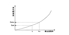
次に、色変換部14は、ステップS50として、目標網点面積率ko,co,mo,yo、及び実網点面積率k,c,m,yに対応する各インキ色の単色網濃度をそれぞれ演算する。この演算には、図5に示すようなマップを用いる。図5は網点面積率を変化させた場合に実測される単色網濃度を特性曲線としてプロットしたマップの一例であり、事前に測定されたデータにより作成されている。図5に示す例では、墨色の目標網点面積率ko、実網点面積率kをマップに照らし合わせることで、マップ中の特性曲線からそれぞれ目標単色網濃度Dakoと実単色網濃度Dakとが求められている。このようにして、色変換部14は、各インキ色の目標単色網濃度Dako,Daco,Damo,Dayoと実単色網濃度Dak,Dac,Dam,Dayとを求める。
Next, in step S50, the
次に、色変換部14は、ステップS60として、目標単色網濃度Dako,Daco,Damo,Dayoと実単色網濃度Dak,Dac,Dam,Dayとの偏差に対応する各インキ色のベタ濃度偏差ΔDsk,ΔDsc,ΔDsm,ΔDsyを演算する。なお、ベタ濃度は網点面積率にも依存しており、同単色網濃度に対しては、網点面積率が高いほどベタ濃度は低くなる。そこで、色変換部14は、図6に示すようなマップを用いて演算を行う。図6は単色ベタ濃度を変化させた場合に実測される単色網濃度を網点面積率毎に特性曲線としてプロットしたマップの一例であり、事前に測定されたデータにより作成されている。色変換部14は、各インキ色について目標網点面積率ko,co,mo,yoに対応する特性曲線を図6に示すマップから選択し、選択した特性曲線に目標単色網濃度Dako,Daco,Damo,Dayoと実単色網濃度Dak,Dac,Dam,Dayとを対応させることにより、ベタ濃度偏差ΔDsk,ΔDsc,ΔDsm,ΔDsyを求める。図6に示す例では、墨色の目標網点面積率koが75%の場合に、目標単色網濃度Dako、実単色網濃度Dakをマップに照らし合わせることで、マップ中の75%特性曲線から墨色のベタ濃度偏差ΔDskが求められている。
Next, in step S60, the
色変換部14で演算された各インキ色のベタ濃度偏差ΔDsk,ΔDsc,ΔDsm,ΔDsyは、インキ供給量演算部15に入力される。インキ供給量演算部15は、ステップS70として、ベタ濃度偏差ΔDsk,ΔDsc,ΔDsm,ΔDsyに対応するキー開度偏差量ΔKk,ΔKc,ΔKm,ΔKyを演算する。キー開度偏差量ΔKk,ΔKc,ΔKm,ΔKyは、各インキキー7の現在のキー開度Kk0,Kc0,Km0,Ky0(前回のステップS100の処理で印刷機の制御装置20に出力したキー開度Kk,Kc,Km,Ky)に対する増減量であり、インキ供給量演算部15は、公知のAPI関数(オートプリセットインキング関数)を用いて演算を行う。API関数は基準濃度にするため各キーゾーンの画線率A(Ak,Ac,Am,Ay)とキー開度K(Kk,Kc,Km,Ky)との対応関係を示した関数である。画線率Aは、ステップS0で用いたものを用いることができる。具体的には、基準濃度Ds(Dsk,Dsc,Dsm,Dsy)に対するベタ濃度偏差ΔDs(ΔDsk,ΔDsc,ΔDsm,ΔDsy)の比率kd(kd=ΔDs/Ds)を求めるとともに、画線率Aに対する基準濃度にするためのキー開度KをAPI関数を使って求め、これらの積としてベタ濃度偏差ΔDsをゼロにするためのキー開度偏差量ΔK(ΔK=kd×K)を求める。
The solid density deviations ΔDsk, ΔDsc, ΔDsm, ΔDsy of each ink color calculated by the
次に、オンライン制御部16は、ステップS80として、インキ供給量演算部15で演算されたキー開度偏差量ΔKk,ΔKc,ΔKm,ΔKyを、各印刷ユニット2a,2b,2c,2dからラインセンサ型IRGB濃度計1までの無駄時間、時間あたりのインキキー7の反応時間、及び印刷速度を考慮して補正する。この補正は、キー開度信号が入力されてからインキキー7が動き、キー開度が変更されて印刷シートに供給されるインキ量が変化し、IRGB濃度計1に反射光量の変化として検出されるまでの時間遅れを考慮したものである。このようなむだ時間の大きいオンラインフィードバック制御系としては、例えばむだ時間補償付PI制御、ファジー制御、ロバスト制御等が最適である。オンライン制御部16は、補正後のキー開度偏差量(オンライン制御用キー開度偏差量)ΔKk,ΔKc,ΔKm,ΔKyに現在のキー開度Kk0,Kc0,Km0,Ky0を加算したオンライン制御用キー開度Kk1,Kc1,Km1,Ky1をキー開度リミッタ演算部17に入力する。
Next, in step S80, the online control unit 16 sends the key opening deviation amounts ΔKk, ΔKc, ΔKm, ΔKy calculated by the ink supply
キー開度リミッタ演算部17は、ステップS90として、オンライン制御部16で演算されたオンライン制御用キー開度Kk1,Kc1,Km1,Ky1に対して上限値を規制する補正を行う。これは、特に低画線部における色変換アルゴリズム(ステップS40,S50,S60の処理)の推定誤差によりキー開度が異常に増大することを規制するための処理である。そして、キー開度リミッタ演算部17は、ステップS100として、上限値を規制したキー開度Kk,Kc,Km,Kyをキー開度信号として印刷機の制御装置20に送信する。
In step S90, the key opening limiter calculation unit 17 performs correction for restricting the upper limit value for the online control key openings Kk1, Kc1, Km1, and Ky1 calculated by the online control unit 16. This is a process for restricting an abnormal increase in the key opening due to an estimation error of the color conversion algorithm (the processes of steps S40 , S50, and S60) particularly in the low image area. Then, in step S100, the key opening limiter calculating unit 17 transmits the key opening Kk, Kc, Km, Ky whose upper limit value is restricted as a key opening signal to the
印刷機の制御装置20は、ステップS110として、演算装置10から送信されたキー開度信号Kk,Kc,Km,Kyに基づき各印刷ユニット2a,2b,2c,2dの各インキキー7の開度を調節する。これにより、各インキ色のインキ供給量は、キーゾーン毎に目標とする色調に見あったものにコントロールされることとなる。
このように、本実施形態にかかる色調制御方法によれば、上述のように印刷機の立ち上がり直後から色調制御が可能であるので、OKシートが得られるまでの時間を短縮することができる。そして、OKシートが得られた後は、図4のフローチャートに従った色調制御が行われる。以下、OKシートが得られた後の色調制御について図4を用いて説明する。
In step S110, the
As described above, according to the color tone control method according to the present embodiment, the color tone control can be performed immediately after the start-up of the printing press as described above. Therefore, the time until an OK sheet is obtained can be shortened. Then, after the OK sheet is obtained, color tone control is performed according to the flowchart of FIG. Hereinafter, the color tone control after the OK sheet is obtained will be described with reference to FIG.
OKシートが得られる前と後とでは、キーゾーン毎に混色網濃度を演算する演算処理の内容に相違がある。すなわち、図4に示すように、OKシートが得られる前のステップS0の処理、及びステップS30の処理に代わり、ステップS31の処理を実施する。
ステップS31では、DSP11は、OKシート中の特定の注目点(注目画素)について目標混色網濃度Io,Ro,Go,Boを設定するとともに、ステップS20で演算された各画素の反射光量i,r,g,bを用いて注目点の実混色網濃度I,R,G,Bを演算する。DSP11はタッチパネル30に接続されており、タッチパネル30にはOKシートの絵柄画像が表示される。注目点はこのタッチパネル30に表示されたOKシート上の特定点を任意に選択することで指定され、演算装置10のDSP11へ入力される。注目点とは印刷シート8上の特に色を一致させたい絵柄の位置であり、特定の一画素、或いは、連続する一塊の複数画素を指定する。オペレータにより注目点が指定されていないキーゾーンについては、DSP11が注目点を自動設定する。この自動設定は、OKシート全体の各インキ色の混色網濃度の分布から、インキ色毎に最も濃度感度の高い画素(最も発色の大きい画素)を演算して自動抽出することにより行う。例えば、キーゾーン絵柄が4色で印刷されている場合、注目点(目標色)は墨、藍、紅、黄の4点となり、キーゾーン内において、その4色が独立にコントロールされることになる。また、例えばオペレータが指定した任意の絵柄ポイント中に無い色及び絵柄面積の少ない色は自動で設定することも出来る。
Before and after the OK sheet is obtained, there is a difference in the contents of the calculation process for calculating the color mixture halftone density for each key zone. That is, as shown in FIG. 4, the process of step S31 is performed instead of the process of step S0 and the process of step S30 before the OK sheet is obtained.
In step S31, the
DSP11は、OKシートの注目点の反射光量i,r,g,bと白紙部分の反射光量とから目標混色網濃度Io,Ro,Go,Boを演算し、印刷シート(本刷りシート)8の注目点の反射光量i,r,g,bと白紙部分の反射光量とから実混色網濃度I,R,G,Bを演算する。なお、注目点が複数画素の集合である場合には、反射光量i,r,g,bを注目点を構成する複数画素で平均処理する。以降のステップS40からステップS110に至る処理内容は、図3のフローチャートに示すOKシートが得られる以前の処理内容と同じであり、演算装置10は、上記のようにして求められた注目点における目標混色網濃度Io,Ro,Go,Boと実混色網濃度I,R,G,Bとに基づき、本刷りシートの絵柄色調をOKシートの絵柄色調に合わせるためのインキキー7のキー開度を演算する。
The
このように、本実施形態にかかる色調制御方法によれば、印刷品質を満たしたOKシートが得られた場合には、OKシートのキーゾーン毎に各インキ色に対応する注目点をそれぞれ設定して、注目点の混色網濃度を目標混色網濃度Io,Ro,Go,Boとして設定するとともに、対応する本刷りシートの注目点の実混色網濃度I,R,G,Bを計測してフィードバック制御するので、1bit−Tiff或いはCIP3・PPFデータのような製版データがない場合でも、絵柄の特定の注目点について色調制御を行うことができる。また、計測値をキーゾーン全体で平均化しないので、キーゾーン内の絵柄の画線率が低くても(例えば、キーゾーン内に1ポイントの小さな絵柄が存在しても)、ラインセンサ型IRBG濃度計1の計測誤差が少なく、安定した色調制御を行うことができる。特に、インキ色毎に最も濃度感度の高い画素を演算して自動抽出して注目画素として設定することで、キーゾーン内の絵柄の画線率が低い場合において、さらに安定した色調制御を行うことができる。具体的には、例えば、シアンの濃度感度Hdcは、計測濃度データ(R,G,B,I)を用いて、“Hdc=R2/(R+G+B+I)”で表すことができ、この濃度感度Hdcの値が最も高い画素がシアンの注目点となる。同様に他のインキ色についても濃度感度が最も高い画素を演算し、その画素を注目点として設定する。
As described above, according to the color tone control method according to the present embodiment, when an OK sheet satisfying the print quality is obtained, the attention point corresponding to each ink color is set for each key zone of the OK sheet. Then, the mixed color halftone density of the target point is set as the target mixed color halftone density Io, Ro, Go, Bo, and the actual mixed color halftone density I, R, G, B of the target point of the corresponding printing sheet is measured and fed back. Therefore, even when there is no plate-making data such as 1-bit-Tiff or CIP3 / PPF data, color tone control can be performed for a specific point of interest of the pattern. In addition, since the measured values are not averaged over the entire key zone, the line sensor type IRBG is used even if the line drawing rate of the pattern in the key zone is low (for example, even if a small pattern of one point exists in the key zone). There are few measurement errors of the
(B)第2実施形態
本発明の第2実施形態について図7を用いて説明する。本実施形態は、図4におけるステップS31に相当するキーゾーン注目点濃度演算の処理方法に特徴があり、図7に示すフローチャートは、本実施形態における処理内容(図4のステップS31に相当する処理内容)を詳細に示している。絵柄色調制御のための他の処理内容については図4を用いて説明したとおりであるので、ここでは説明を省略する。
(B) Second Embodiment A second embodiment of the present invention will be described with reference to FIG. The present embodiment is characterized by a key zone attention point density calculation processing method corresponding to step S31 in FIG. 4, and the flowchart shown in FIG. 7 shows the processing contents in this embodiment (the processing corresponding to step S31 in FIG. 4). Details). Since the other processing contents for the design color tone control are as described with reference to FIG. 4 , the description is omitted here.
本実施形態では外部(例えば、印刷会社に対する印刷依頼元、新聞社の印刷工場に対する新聞社の本社、等)から網点面積率データを取得できる場合を想定し、ここでは、新聞社の本社から新聞紙の紙面情報がビットマップデータ(1bit−Tiff製版用データ)の形式で印刷工場に送信されてくるものとする。まず、ステップS311では、送信されたビットマップデータを印刷機のフォーマットに応じたCIP3・PPFデータ相当の低解像度データに変換し、この低解像度データを画素面積率データとして用いる。この解像度の変換処理は一般的なCIP3・PPFデータとの共用を図るためであるが、後の処理においてビットマップデータそのものを画素面積率データとして用いることも可能である。 In the present embodiment, it is assumed that halftone dot area ratio data can be acquired from the outside (for example, a printing request source for a printing company, a newspaper company headquarters for a newspaper printing factory, etc.). Assume that newspaper page information is transmitted to the printing factory in the form of bitmap data (1-bit-Tiff platemaking data). First, in step S311, the transmitted bitmap data is converted into low resolution data equivalent to CIP3 / PPF data corresponding to the format of the printing press, and this low resolution data is used as pixel area ratio data. This resolution conversion process is for sharing with general CIP3 / PPF data, but it is also possible to use the bitmap data itself as pixel area ratio data in subsequent processes.
ステップS312では、インキ供給単位幅毎に各インキ色に対応する注目点をそれぞれ設定する。注目点の設定方法としては、新聞社の本社から送信されたビットマップデータを用いてタッチパネル30に新聞紙面の絵柄画像を表示し、このタッチパネル30に表示された新聞紙面上の特定点をオペレータが任意に選択する方法がある。また、各色・各画素の網点面積率に対して最も自己相関が大きい画素を演算して自動抽出し、注目点(注目画素)として自動設定する方法もある。具体的には、例えば、シアンの自己相関感度Hcは、画素面積率データ(c,m,y,k)を用いて、“Hc=c2/(c+m+y+k)”で表すことができ、この自己相関感度Hcの値が最も高い画素がシアンの注目点となる。同様に他のインキ色についても自己相関感度が最も高い画素を演算し、その画素を注目点として設定する。
In step S312, the attention point corresponding to each ink color is set for each ink supply unit width. As an attention point setting method, a bitmap image transmitted from the head office of a newspaper company is used to display a picture image of a newspaper on the
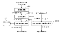
ステップS313では、データベース141に記録された変換テーブルを用いて注目点の網点面積率ki,ci,mi,yiを混色網濃度に変換し、それを目標混色網濃度Io,Ro,Go,Boとして設定する。また、ステップS314では、ステップS20で演算された各画素の反射光量を用いて注目点の実混色網濃度I,R,G,Bを演算する。実混色網濃度I,R,G,Bの演算方法については第1実施形態で説明したので、ここではその説明を省略する。
In step S313, the halftone dot area ratio ki, ci, mi, yi of the target point is converted into a mixed color halftone density using the conversion table recorded in the
本実施形態の方法によれば、OKシートが印刷されるのを待つまでもなく、印刷開始直後から絵柄の特定の注目点について正確に色調制御を行うことが可能になる。したがって、OKシートが得られるまでの時間をより短縮して損紙を低減することができる。特に、各色・各画素の網点面積率に対して最も自己相関が大きい画素を注目点として設定する場合には、濃度感度の最も高い画素が注目点に選ばれセンシング感度が向上するため、所望の色調に速やかに合わせることが可能になる。 According to the method of the present embodiment, it is possible to accurately perform color tone control for a specific attention point of a pattern immediately after the start of printing without waiting for an OK sheet to be printed. Accordingly, it is possible to further reduce the time until the OK sheet is obtained and reduce the waste paper. In particular, when the pixel having the highest autocorrelation with respect to the dot area ratio of each color / pixel is set as the attention point, the pixel having the highest density sensitivity is selected as the attention point, and the sensing sensitivity is improved. It is possible to quickly match the color tone of the.
なお、ステップS312では、複数の画素からなる画素群を注目点として選定してもよい。例えば、オペレータが任意の画素が選択されたり、最も自己相関感度の高い画素が自動選択されたら、その周辺の画素も含めた画素群を注目点として選定する。注目点に含める周辺画素の画素数やその選択パターンは固定(例えば、選択或いは自動抽出された画素を囲む周辺8画素)してもよいが、好ましくは、選択或いは自動抽出された画素の絵柄内での位置等を考慮して外乱の影響が抑制されるように設定する。そして、画素群を注目点として選定する場合は、ステップS313では画素群の平均混色網濃度を目標混色網濃度として設定し、ステップS314では画素群の実平均混色網濃度を測定する。これによれば、印刷紙面の蛇行や天地ずれによって計測データが変動することが少なくなるので、安定したフィードバック制御が可能になる。 In step S312, a pixel group including a plurality of pixels may be selected as a point of interest. For example, when an arbitrary pixel is selected by the operator or a pixel having the highest autocorrelation sensitivity is automatically selected, a pixel group including surrounding pixels is selected as a point of interest. The number of surrounding pixels included in the attention point and the selection pattern thereof may be fixed (for example, the surrounding 8 pixels surrounding the selected or automatically extracted pixels), but preferably within the pattern of the selected or automatically extracted pixels. It is set so that the influence of the disturbance is suppressed in consideration of the position at. When the pixel group is selected as a point of interest, the average color mixture halftone density of the pixel group is set as the target color mixture halftone density in step S313, and the actual average color mixture halftone density of the pixel group is measured in step S314. According to this, since the measurement data is less likely to fluctuate due to meandering or vertical displacement of the printing paper surface, stable feedback control is possible.
(C)第3実施形態
本発明の第3実施形態について図8を用いて説明する。本実施形態も第2実施形態と同様、図4におけるステップS31に相当するキーゾーン注目点濃度演算の処理方法に特徴があり、図8に示すフローチャートは、本実施形態における処理内容(図4のステップS31に相当する処理内容)を詳細に示している。絵柄色調制御のための他の処理内容については図4を用いて説明したとおりであるので、ここでは説明を省略する。
(C) Third Embodiment A third embodiment of the present invention will be described with reference to FIG. Similar to the second embodiment, this embodiment is also characterized by a key zone attention point density processing method corresponding to step S31 in FIG. 4, and the flowchart shown in FIG. 8 shows the processing contents (FIG. 4 in FIG. 4). The processing content corresponding to step S31) is shown in detail. Since the other processing contents for the design color tone control are as described with reference to FIG. 4, the description is omitted here.
本実施形態も第2実施形態と同様、新聞社の本社から新聞紙の紙面情報がビットマップデータの形式で印刷工場に送信されてくるものとする。ただし、本実施形態では、第2実施形態との相違点として、紙面情報のビットマップデータに加え、紙面の色情報を作成した入力装置のICCプロファイルも送信されてくるものとする。ステップS321では、ビットマップデータを印刷機のフォーマットに応じたCIP3・PPFデータ相当の低解像度データに変換し、ステップS322では、インキ供給単位幅毎に各インキ色に対応する注目点をそれぞれ設定する。これらステップS321,S322の処理内容は、第2実施形態に係るステップS311,S312の処理内容と同様であるので、その詳細な説明は省略する。 Similarly to the second embodiment, in this embodiment, it is assumed that the page information of the newspaper is transmitted from the head office of the newspaper company to the printing factory in the form of bitmap data. However, in the present embodiment, as a difference from the second embodiment, in addition to the bitmap data of the page information, the ICC profile of the input device that created the color information of the page is also transmitted. In step S321, the bitmap data is converted into low-resolution data corresponding to CIP3 / PPF data corresponding to the format of the printing press. In step S322, attention points corresponding to each ink color are set for each ink supply unit width. . Since the processing contents of these steps S321 and S322 are the same as the processing contents of steps S311 and S312 according to the second embodiment, detailed description thereof will be omitted.
ステップS323では、新聞社本社から送信されたICCプロファイルを用いて注目点の網点面積率ki,ci,mi,yiを色座標値L,a,bに変換する。そして、ステップS324では、データベース141に記憶された変換テーブルを用いてステップS323で求めた色座標値L,a,bを混色網濃度に変換する。しかしながら、色座標値は3次元情報であるのに混色網濃度は4次元情報であるので、色座標値に対応する混色網濃度は一意には定まらない。混色網濃度を一意には定めるには、何らかの追加情報が必要になるが、ICCプロファイルからは色座標値という3次元情報しか得ることができない。
In step S323, the halftone dot area ratio ki, ci, mi, yi of the target point is converted into the color coordinate values L, a, b using the ICC profile transmitted from the newspaper company headquarters. In step S324, using the conversion table stored in the
そこで、本実施形態では以下のステップで説明するように、印刷絵柄の網点面積率データ、すなわち、色座標値L,a,bに対応する網点面積率ki,ci,mi,yiを利用することによって、このような3次元情報から4次元情報への展開において、候補となる無数の4次元情報の中から最も適当な4次元情報を選出することを行う。
まず、ステップS325において、データベース141に記憶された変換テーブルを用いて注目点の網点面積率ki,ci,mi,yiを色座標値L’,a’,b’に変換する。ステップS326では、ステップS323で求めた色座標値L,a,bとステップS325で求めた色座標値L’,a’,b’との色差ΔL’,Δa’,Δb’を演算し、ステップS327において、この色差ΔL’,Δa’,Δb’に対応する網点面積率の変化量Δk’,Δc’,Δm’,Δy’を演算する。網点面積率の各変化量は、色座標値の各変化量を用いて下式で近似することができる。但し、下式におけるa,bは線形近似係数である。
Therefore, in the present embodiment, as will be described in the following steps, halftone dot area ratio data of the printed pattern, that is, halftone dot area ratios ki, ci, mi, yi corresponding to the color coordinate values L, a, b are used. By doing this, in the development from such 3D information to 4D information, the most appropriate 4D information is selected from among a myriad of 4D information candidates.
First, in step S325, the halftone dot area ratio ki, ci, mi, yi of the target point is converted into color coordinate values L ′, a ′, b ′ using the conversion table stored in the
Δc’=a11×ΔL’+a12×Δa’+a13×Δb’+bc ・・・(1)
Δm’=a21×ΔL’+a22×Δa’+a23×Δb’+bm ・・・(2)
Δy’=a31×ΔL’+a32×Δa’+a33×Δb’+by ・・・(3)
Δk’=a41×ΔL’+a42×Δa’+a43×Δb’+bk ・・・(4)
ステップS328では、注目点の網点面積率ki,ci,mi,yiにステップS327で求めた変化量Δk’,Δc’,Δm’,Δy’を加算し、その値を仮想網点面積率k’,c’,m’,y’として設定する。ステップS329では、この仮想網点面積率k’,c’,m’,y’をデータベース141に記録された変換テーブルに照合し、ステップS324で求めた複数の混色網濃度候補の中から仮想網点面積率k’,c’,m’,y’に最も対応するものを選択する。選択された混色網濃度は目標混色網濃度Io,Ro,Go,Boとして設定され、ステップS330で演算される注目点の実混色網濃度I,R,G,Bとともに、ステップS40以降の処理で用いられる。
Δc ′ = a11 × ΔL ′ + a12 × Δa ′ + a13 × Δb ′ + bc (1)
Δm ′ = a21 × ΔL ′ + a22 × Δa ′ + a23 × Δb ′ + bm (2)
Δy ′ = a31 × ΔL ′ + a32 × Δa ′ + a33 × Δb ′ + by (3)
Δk ′ = a41 × ΔL ′ + a42 × Δa ′ + a43 × Δb ′ + bk (4)
In step S328, the amount of change Δk ′, Δc ′, Δm ′, Δy ′ obtained in step S327 is added to the halftone dot area ratio ki, ci, mi, yi of the target point, and the value is added to the virtual halftone dot area ratio k. Set as ', c', m ', y'. In step S329, the virtual dot area ratios k ′, c ′, m ′, y ′ are collated with the conversion table recorded in the
本方法によれば、印刷依頼元等から得たICCプロファイルを用いて色調を制御することができるので、従来行われている校正刷りと比較しながらの色合わせに比較して、印刷依頼元等が所望する色調に正確、且つ容易に色合わせすることができる。したがって、本方法によれば、OKシートが得られるまでの損紙の発生量を大幅に低減することもできる。 According to this method, since the color tone can be controlled using the ICC profile obtained from the print requester or the like, the print requester or the like can be compared with the conventional color matching compared with the proof print. Can be accurately and easily matched to the desired color tone. Therefore, according to this method, it is possible to significantly reduce the amount of lost paper until an OK sheet is obtained.
(D)第4実施形態
本発明の第4実施形態について図9を用いて説明する。本実施形態は色調制御のための補助的な方法についての提案であり、本方法は第1〜第3実施形態の色調制御の何れにも付加的に適用することができる。
ステップS401では、データベース141に記録された変換テーブルを用いて目標混色網濃度Io,Ro,Go,Boを色座標値に変換する。また、ステップS402では、同じく変換テーブルを用いて実混色網濃度I,R,G,Bを色座標値に変換する。そして、ステップS403では、ステップS401で求めた目標色座標値Lo,ao,boとステップS402で求めた実色座標値L,a,bとの色差ΔE*(=√{(Lo−L)2+(ao−a)2+(bo−b)2}を演算し、ステップS404では、実色座標値L,a,bと色差ΔE*とを表示装置32に表示する。
(D) Fourth Embodiment A fourth embodiment of the present invention will be described with reference to FIG. This embodiment is a proposal for an auxiliary method for color tone control, and this method can be additionally applied to any of the color tone controls of the first to third embodiments.
In step S401, the target color mixture halftone densities Io, Ro, Go, Bo are converted into color coordinate values using the conversion table recorded in the
L*a*b*表色系は人間の色刺激に対して座標がリニアになっている表色系であるので、本方法のように注目点の色を色座標値L,a,bで表したり、注目点の目標色に対する色差ΔE*を表示することで、オペレータに対して色がどれだけのレベルで合っているか直感的に分かりやすくすることができる。したがって、本方法を第1〜第3実施形態の色調制御に追加実施することで、オペレータの判断を補助してより正確な色合わせが可能になる。 Since the L * a * b * color system is a color system whose coordinates are linear with respect to human color stimuli, the color of the point of interest is represented by color coordinate values L, a, and b as in this method. By displaying or displaying the color difference ΔE * with respect to the target color of the target point, it is possible to intuitively understand how much the color matches the operator. Therefore, by performing this method in addition to the color tone control of the first to third embodiments, more accurate color matching is possible with assistance from the operator.
(E)その他
以上、本発明の実施形態について説明したが、本発明の実施の形態は上記のものに限定されない。例えば、第1実施形態では、各インキ色の網点面積率と混色網濃度とを関連付けるデータベース141を備える方法の他、各インキ色の網点面積率と混色網濃度との対応関係を規定した公知のノイゲバウアーの式を記憶しておき、この式に各インキ色の網点面積率を当てはめることで混色網濃度を算出する方法を採ることもできる。
(E) Others Although the embodiment of the present invention has been described above, the embodiment of the present invention is not limited to the above. For example, in the first embodiment, in addition to the method including the
また、図6に示すようなマップを用いて目標単色網濃度と実単色網濃度との偏差に対応する各インキ色のベタ濃度偏差を求める方法の他、網点面積率と単色網濃度とベタ濃度との対応関係を規定した公知のユールニールセンの式を記憶しておき、この式に目標網点面積率、実網点面積率及び単色網濃度を当てはめることでベタ濃度偏差を算出する方法もある。 In addition to a method for obtaining a solid density deviation of each ink color corresponding to a deviation between the target monochrome color density and the actual monochrome color density using a map as shown in FIG. 6, the dot area ratio, the monochrome color density, and the solid color density. A method of calculating a solid density deviation by storing a known Yule-Nielsen formula that defines the correspondence with density and applying the target halftone dot area ratio, actual halftone dot area percentage, and monochrome halftone density to this formula is also available. is there.
また、実施形態では、ラインセンサ型のIRGB濃度計を用いているが、スポット型のIRGB濃度計を用いて印刷シート上を2次元的に走査するようにしてもよい。 In the embodiment, a line sensor type IRGB densitometer is used, but a spot type IRGB densitometer may be used to scan the print sheet two-dimensionally.
1 ラインセンサ型IRGB濃度計
2a,2b,2c,2d 印刷ユニット
3 ブランケット胴
4 版胴
5 インキローラ群
6 インキ元ローラ
7 インキキー
8 印刷シート
10 演算装置
11 DSP
12 PC
14 色変換部
15 インキ供給量演算部
16 オンライン制御部
17 キー開度リミッタ演算部
20 印刷機内蔵の制御装置
30 タッチパネル
32 表示装置
DESCRIPTION OF
12 PC
14
Claims (18)
IRGB濃度計を用いて、印刷で得られた本刷りシートの上記インキ供給単位幅毎の実混色網濃度を計測するステップと、
予め設定した、墨(k),藍(c),紅(m),黄(y)に係る網点面積率と上記混色網濃度との対応関係に基づき、上記目標混色網濃度に対応する各インキ色の目標網点面積率を求めるとともに、上記実混色網濃度に対応する各インキ色の実網点面積率を求めるステップと、
予め設定した、上記網点面積率と単色網濃度との対応関係に基づき、上記各インキ色の目標網点面積率に対応する目標単色網濃度と上記実網点面積率に対応する実単色網濃度とを求めるステップと、
予め設定した、上記網点面積率毎の単色網濃度と単色ベタ濃度との対応関係に基づき、上記各インキ色の目標網点面積率に応じて選択された上記目標単色網濃度と上記実単色網濃度との偏差に対応するベタ濃度偏差を求めるステップと、
上記ベタ濃度偏差に基づき、上記実混色網濃度を上記目標混色網濃度に近づけるように上記インキ供給単位幅毎にインキ供給量を調整するステップと、
を実行することを特徴とする、印刷機の絵柄色調制御方法。 Mixed-color halftone density for I (infrared light), R (red), G (green), and B (blue) for each ink supply unit width when the printed pattern is divided by the ink supply unit width of the ink supply device Setting a target color mixture halftone density with the target value as a target value;
Using an IRGB densitometer to measure the actual color mixture halftone density for each ink supply unit width of the main printed sheet obtained by printing;
Each of the colors corresponding to the target mixed color halftone density is set based on the correspondence relationship between the halftone dot area ratio relating to black (k), indigo (c), red (m), and yellow (y) and the mixed color halftone density. Obtaining a target halftone dot area ratio of the ink color and obtaining an actual halftone dot area ratio of each ink color corresponding to the actual mixed color halftone density;
Based on a preset correspondence relationship between the halftone dot area ratio and the single color halftone density, the target single color halftone density corresponding to the target halftone dot area ratio of each ink color and the real single color halftone dot corresponding to the actual halftone dot area ratio. Determining the concentration;
The target single color halftone density and the actual single color selected according to the target halftone dot area ratio of each ink color based on the correspondence relationship between the monochrome halftone density and the single color solid density for each halftone dot area ratio set in advance. Obtaining a solid density deviation corresponding to the deviation from the net density;
Adjusting the ink supply amount for each ink supply unit width so that the actual mixed color halftone density approaches the target mixed color halftone density based on the solid density deviation;
The pattern color tone control method of a printing press characterized by performing these.
ことを特徴とする、請求項1記載の印刷機の絵柄色調制御方法。 In the step of adjusting the ink supply amount described above, determine the ink key opening deviation is increased or decreased amount with respect to ink key opening for each of the ink supplying unit widths based on the solid density difference, the ink keys opening based on the ink key opening deviation 2. The pattern color tone control method for a printing press according to claim 1, wherein the actual mixed color halftone density is brought close to the target mixed color halftone density by adjusting the ink supply amount by adjusting the ink supply amount.
ことを特徴とする、請求項2記載の印刷機の絵柄色調制御方法。 In the step of setting the target mixed color halftone density, the data of the line drawing rate for each ink supply unit width of each ink color in the print pattern to be printed is acquired as corresponding to the halftone dot area ratio, and Based on the correspondence relationship between the halftone dot area ratio and the mixed color halftone density, the mixed color halftone density corresponding to the image drawing ratio is obtained, and the mixed color halftone density corresponding to the image drawing ratio is set as the target mixed color halftone density. The pattern color tone control method for a printing press according to claim 2.
上記目標混色網濃度を設定するステップでは、上記OKシートの絵柄を構成する画素の中から上記インキ供給単位幅毎に各インキ色に対応する注目画素をそれぞれ選定して、上記注目画素の混色網濃度を上記目標混色網濃度として設定し、
上記実混色網濃度を計測するステップでは、上記注目画素の実混色網濃度を計測する
ことを特徴とする、請求項2又は3記載の印刷機の絵柄色調制御方法。 When an OK sheet that satisfies the print quality is obtained,
In the step of setting the target mixed color halftone density, a target pixel corresponding to each ink color is selected for each ink supply unit width from the pixels constituting the pattern of the OK sheet, and the mixed color network of the target pixel is selected. Set the density as the target mixed color halftone density,
4. The pattern color tone control method for a printing press according to claim 2, wherein in the step of measuring the actual mixed color halftone density, the actual mixed color halftone density of the target pixel is measured.
外部から印刷対象絵柄のkcmy網点面積率データを取得するステップと、
上記印刷対象絵柄を構成する画素の中から上記インキ供給単位幅毎に各インキ色に対応する注目画素をそれぞれ選定するステップと、
予め設定した網点面積率と混色網濃度との対応関係に基づき上記注目画素の網点面積率を混色網濃度に変換するステップとを有し、
上記目標混色網濃度を設定するステップでは、上記注目画素の混色網濃度を上記目標混色網濃度として設定し、
上記実混色網濃度を計測するステップでは、上記注目画素の実混色網濃度を計測する
ことを特徴とする、請求項1記載の印刷機の絵柄色調制御方法。 The step of setting the target mixed color halftone density includes
Obtaining kcmy halftone dot area ratio data of the print target pattern from the outside;
Selecting each pixel of interest corresponding to each ink color for each ink supply unit width from the pixels constituting the print target picture;
Converting the halftone dot area ratio of the pixel of interest into a mixed color halftone density based on a correspondence relationship between a predetermined halftone dot area ratio and the mixed color halftone density, and
In the step of setting the target color mixture halftone density, the color mixture halftone density of the target pixel is set as the target color mixture halftone density,
2. The picture color tone control method for a printing press according to claim 1, wherein the step of measuring the actual mixed color halftone density measures the actual mixed color halftone density of the target pixel.
外部から印刷対象絵柄のkcmy網点面積率データとICCプロファイルとを取得するステップと、
上記印刷対象絵柄を構成する画素の中から上記インキ供給単位幅毎に各インキ色に対応する注目画素をそれぞれ選定するステップと、
上記注目画素の網点面積率を上記ICCプロファイルと上記IRGB濃度計のデバイスプロファイルとを用いて混色網濃度に変換するステップとを有し、
上記目標混色網濃度を設定するステップでは、上記注目画素の混色網濃度を上記目標混色網濃度として設定し、
上記実混色網濃度を計測するステップでは、上記注目画素の実混色網濃度を計測する
ことを特徴とする、請求項1記載の印刷機の絵柄色調制御方法。 The step of setting the target mixed color halftone density includes
Obtaining kcmy halftone dot area ratio data and ICC profile of the pattern to be printed from the outside;
Selecting each pixel of interest corresponding to each ink color for each ink supply unit width from the pixels constituting the print target picture;
Converting the halftone dot area ratio of the pixel of interest into a mixed color halftone density using the ICC profile and the device profile of the IRGB densitometer,
In the step of setting the target color mixture halftone density, the color mixture halftone density of the target pixel is set as the target color mixture halftone density,
2. The picture color tone control method for a printing press according to claim 1, wherein the step of measuring the actual mixed color halftone density measures the actual mixed color halftone density of the target pixel.
上記注目画素の網点面積率を混色網濃度に変換するステップは、
上記ICCプロファイルを用いて上記注目画素の網点面積率を色座標値に変換するステップと、
上記変換テーブルを用いて上記注目画素の色座標値に対応する複数の混色網濃度候補を求めるステップと、
上記変換テーブルを用いて上記注目画素の網点面積率を色座標値に変換するステップと、
上記ICCプロファイルによる変換、及び上記変換テーブルによる変換によって得られた上記2つの色座標値間の色差を求めるステップと、
上記色差に対応する網点面積率の変化量を演算するステップと、
上記注目画素の網点面積率に上記変化量を加算した仮想網点面積率を求めるステップと、
上記変換テーブルを参照して上記複数の混色網濃度候補のうち上記仮想網点面積率に最も対応するものを選択するステップとを有し、
上記注目画素の網点面積率を混色網濃度に変換するステップでは、選択した混色網濃度候補を上記注目画素の混色網濃度として設定する
ことを特徴とする、請求項6記載の印刷機の絵柄色調制御方法。 The device profile is a conversion table that defines the correspondence between the dot area ratio, the mixed color halftone density, and the color coordinate value.
The step of converting the halftone dot area ratio of the target pixel into a mixed color halftone density is as follows:
Converting the dot area ratio of the pixel of interest into a color coordinate value using the ICC profile;
Obtaining a plurality of color mixture halftone density candidates corresponding to the color coordinate values of the target pixel using the conversion table;
Converting the dot area ratio of the pixel of interest into a color coordinate value using the conversion table;
Obtaining a color difference between the two color coordinate values obtained by the conversion by the ICC profile and the conversion by the conversion table;
Calculating the amount of change in the halftone dot area ratio corresponding to the color difference;
Obtaining a virtual dot area ratio obtained by adding the amount of change to the dot area ratio of the pixel of interest;
Selecting the one corresponding to the virtual halftone dot area ratio among the plurality of mixed color halftone density candidates with reference to the conversion table,
7. The image of a printing press according to claim 6, wherein in the step of converting the halftone dot area ratio of the target pixel into a mixed color halftone density, the selected mixed color halftone density candidate is set as the mixed color halftone density of the target pixel. Color tone control method.
ことを特徴とする、請求項5〜7のいずれか1項に記載の印刷機の絵柄色調制御方法。 In the step of acquiring the kcmy halftone dot area ratio data, first, the bitmap data of the pattern to be printed is acquired, and the bitmap data converted into low resolution data equivalent to CIP3 / PPF data is the kcmy halftone dot. The pattern color tone control method for a printing press according to any one of claims 5 to 7, wherein the pattern color tone control method is used as area ratio data.
上記の混色網濃度と色座標値との対応関係に基づき、上記目標混色網濃度に対応する目標色座標値を求めるステップと、
上記実色座標値と上記目標色座標値との色差を求めるステップと、
上記実色座標値及び上記色差を表示装置に表示するステップとをさらに実行することを特徴とする、請求項4〜8のいずれか1項に記載の印刷機の絵柄色調制御方法。 Obtaining a real color coordinate value corresponding to an actual color mixture halftone density of the pixel of interest measured by the IRGB densitometer based on a correspondence relationship between a preset color mixture halftone density and a color coordinate value;
Obtaining a target color coordinate value corresponding to the target color mixture halftone density based on the correspondence relationship between the color mixture halftone density and the color coordinate value;
And vinegar STEP determine the color difference between the actual color coordinate value and the target color coordinate value,
The pattern color tone control method for a printing press according to any one of claims 4 to 8, further comprising the step of displaying the actual color coordinate value and the color difference on a display device.
ことを特徴とする、請求項5〜7のいずれか1項に記載の印刷機の絵柄色調制御方法。
Hx=x2/(c+m+y+k)
ただし、(xはk,c,m,yのいずれか) The pixel of interest is an autocorrelation sensitivity based on the dot area ratio of ink color x and the dot area ratios of black (k), indigo (c), red (m), and yellow (y) for each ink color. The printing according to any one of claims 5 to 7, characterized in that it is set by automatically extracting a pixel having the largest value defined by the following formula as Hx as a pixel of interest of the ink color. How to control the pattern color of the machine.
Hx = x 2 / (c + m + y + k)
However, (x is any of k, c, m, y)
上記実混色網濃度を計測するステップでは、上記注目画素として選定された画素群の実平均混色網濃度を計測する
ことを特徴とする、請求項10記載の印刷機の絵柄色調制御方法。 In the step of setting the target mixed color halftone density, an average mixed color halftone density of the pixel group selected as the target pixel is set as the target mixed color halftone density,
11. The picture color tone control method for a printing press according to claim 10, wherein in the step of measuring the actual mixed color halftone density, the actual average mixed color halftone density of the pixel group selected as the target pixel is measured.
ことを特徴とする、請求項1記載の印刷機の絵柄色調制御方法。 The step from the step of setting the target color mixture halftone density to the step of measuring the actual color mixture halftone density to the step of adjusting the ink supply amount is repeatedly executed for a predetermined period. Item 2. A color tone control method for a printing press according to Item 1.
印刷絵柄を上記インキ供給装置のインキ供給単位幅で分割したときの上記インキ供給単位幅毎に、I(赤外光),R(赤),G(緑),B(青)に係る混色網濃度を目標値とした目標混色網濃度を設定する目標混色網濃度設定手段と、
印刷で得られる本刷りシートの走行ライン上に配置されたIRGB濃度計と、
上記IRGB濃度計を用いて上記本刷りシートの上記インキ供給単位幅毎の実混色網濃度を計測する混色網濃度計測手段と、
予め設定した、墨(k),藍(c),紅(m),黄(y)に係る網点面積率と上記混色網濃度との対応関係に基づき、上記目標混色網濃度設定手段により設定された上記目標混色網濃度に対応する各インキ色の目標網点面積率を求める目標網点面積率演算手段と、
上記墨(k),藍(c),紅(m),黄(y)に係る網点面積率と上記混色網濃度との対応関係に基づき、上記混色網濃度計測手段により計測された上記実混色網濃度に対応する各インキ色の実網点面積率を求める実網点面積率演算手段と、
予め設定した上記網点面積率と単色網濃度との対応関係に基づき、上記各インキ色の上記目標網点面積率に対応する目標単色網濃度を求める目標単色網濃度演算手段と、
上記の網点面積率と単色網濃度との対応関係に基づき、上記実網点面積率に対応する実単色網濃度を求める実単色網濃度演算手段と、
予め設定した上記網点面積率毎の単色網濃度と単色ベタ濃度との対応関係に基づき、上記各インキ色の目標網点面積率に応じて選択された上記目標単色網濃度と上記実単色網濃度との偏差に対応するベタ濃度偏差を求めるベタ濃度偏差演算手段と、
上記ベタ濃度偏差に基づき、上記実混色網濃度が上記目標混色網濃度に近づくように上記インキ供給単位幅毎にインキ供給量を調整するインキ供給量調整手段と、を備えた
絵柄色調制御装置を有する
ことを特徴とする、印刷機。 An ink supply device for supplying ink to each area divided in the printing width direction;
A mixed color network for I (infrared light), R (red), G (green), and B (blue) for each of the ink supply unit widths when the printed pattern is divided by the ink supply unit width of the ink supply device. Target mixed color halftone density setting means for setting a target mixed color halftone density with a density as a target value;
An IRGB densitometer arranged on a running line of a main printing sheet obtained by printing;
Color mixture halftone density measuring means for measuring an actual color mixture halftone density for each ink supply unit width of the main printing sheet using the IRGB densitometer;
Set by the target mixed color halftone density setting means based on the correspondence relationship between the halftone dot area ratio relating to black (k), indigo (c), red (m), yellow (y) and the mixed color halftone density. A target halftone dot area ratio calculating means for obtaining a target halftone dot area ratio of each ink color corresponding to the target mixed color halftone density,
Based on the correspondence relationship between the halftone dot area ratio relating to the black (k), indigo (c), red (m), and yellow (y) and the mixed color halftone density, the actual color measured by the mixed color halftone density measuring unit is measured. An actual halftone dot area ratio calculating means for obtaining an actual halftone dot area ratio of each ink color corresponding to the mixed color halftone density;
A target monochromatic halftone density calculating means for obtaining a target monochromatic halftone density corresponding to the target halftone dot area ratio of each ink color based on the correspondence relationship between the halftone dot area ratio and the monochromatic halftone density set in advance;
Based on the correspondence between the halftone dot area ratio and the monochromatic halftone density, an actual monochromatic halftone density calculating means for obtaining an actual monochromatic halftone density corresponding to the actual halftone dot area ratio;
The target single color halftone density and the actual single color halftone dot selected according to the target halftone dot area ratio of each ink color based on the correspondence between the single color halftone density and the single color solid density for each halftone dot area ratio set in advance. A solid density deviation calculating means for obtaining a solid density deviation corresponding to the deviation from the density;
An ink supply amount adjusting means for adjusting an ink supply amount for each ink supply unit width so that the actual mixed color halftone density approaches the target mixed color halftone density based on the solid density deviation; A printing machine, comprising:
ことを特徴とする、請求項13記載の印刷機。 It said ink supply amount adjusting unit determines the ink key opening deviation is increased or decreased amount with respect to ink key opening for each of the ink supplying unit widths based on the solid density difference, to adjust the ink key opening degree based on the ink key opening deviation 14. The printing press according to claim 13, wherein the actual mixed color halftone density is brought close to the target mixed color halftone density by adjusting an ink supply amount.
上記目標網点面積率演算手段及び上記実網点面積率演算手段は、上記変換テーブルを用いて上記目標網点面積率或いは上記実網点面積率を求めるように構成されている
ことを特徴とする、請求項14記載の印刷機。 A conversion table that defines the correspondence between the dot area ratio, the mixed color halftone density, and the color coordinate value in the IRGB densitometer;
The target halftone dot area ratio calculating means and the real halftone dot area ratio calculating means are configured to obtain the target halftone dot area ratio or the real halftone dot area ratio using the conversion table. The printing machine according to claim 14.
外部から印刷対象絵柄のkcmy網点面積率データを受信する受信手段と、
上記印刷対象絵柄を構成する画素の中から上記インキ供給単位幅毎に各インキ色に対応する注目画素をそれぞれ設定する注目画素設定手段と、
上記変換テーブルを用いて上記注目画素の網点面積率を混色網濃度に変換する変換手段とを備え、上記注目画素の混色網濃度を上記目標混色網濃度として設定するように構成され、
上記混色網濃度計測手段は、上記注目画素の実混色網濃度を計測するように構成されている
ことを特徴とする、請求項15記載の印刷機。 The target mixed color halftone density setting means includes:
Receiving means for receiving kcmy halftone dot area ratio data of a print target pattern from outside;
Pixel-of-interest setting means for setting each pixel of interest corresponding to each ink color for each of the ink supply unit widths from among the pixels constituting the pattern to be printed;
Conversion means for converting the halftone dot area ratio of the target pixel into a mixed color halftone density using the conversion table, and configured to set the mixed color halftone density of the target pixel as the target mixed color halftone density,
16. The printing press according to claim 15 , wherein the mixed color halftone density measuring unit is configured to measure an actual mixed color halftone density of the target pixel.
外部から印刷対象絵柄のkcmy網点面積率データとICCプロファイルとを受信する受信手段と、
上記印刷対象絵柄を構成する画素の中から上記インキ供給単位幅毎に各インキ色に対応する注目画素をそれぞれ設定する注目画素設定手段と、
上記注目画素の網点面積率を上記ICCプロファイルと上記変換テーブルとを用いて混色網濃度に変換する変換手段とを備え、上記注目画素の混色網濃度を上記目標混色網濃度として設定するように構成され、
上記混色網濃度計測手段は、上記注目画素の実混色網濃度を計測するように構成されている
ことを特徴とする、請求項15記載の印刷機。 The target mixed color halftone density setting means includes:
Receiving means for receiving the kcmy halftone dot area ratio data and ICC profile of the pattern to be printed from outside;
Pixel-of-interest setting means for setting each pixel of interest corresponding to each ink color for each of the ink supply unit widths from among the pixels constituting the pattern to be printed;
Conversion means for converting the halftone dot area ratio of the target pixel into a mixed color halftone density using the ICC profile and the conversion table, and setting the mixed color halftone density of the target pixel as the target mixed color halftone density. Configured,
16. The printing press according to claim 15 , wherein the mixed color halftone density measuring unit is configured to measure an actual mixed color halftone density of the target pixel.
上記変換テーブルを用いて上記目標混色網濃度に対応する目標色座標値を求める目標色座標値演算手段と、
上記実色座標値と上記目標色座標値との色差を求める色差演算手段と、
上記実色座標値及び上記色差を表示装置に表示する表示手段と、をさらに備えたことを特徴とする、請求項15〜17のいずれか1項に記載の印刷機。 An actual color coordinate value calculating means for obtaining an actual color coordinate value corresponding to the actual mixed color halftone density using the conversion table;
A target color coordinate value calculating means for obtaining a target color coordinate value corresponding to the target color mixture halftone density using the conversion table;
Color difference calculating means for obtaining a color difference between the actual color coordinate value and the target color coordinate value;
The printing press according to any one of claims 15 to 17, further comprising display means for displaying the actual color coordinate value and the color difference on a display device.
Priority Applications (2)
| Application Number | Priority Date | Filing Date | Title |
|---|---|---|---|
| JP2003288582A JP3825427B2 (en) | 2002-08-26 | 2003-08-07 | Pattern color control method for printing machine and printing machine |
| US11/295,496 US7573613B2 (en) | 2003-08-07 | 2005-12-07 | Method and apparatus for controlling picture color tone of printing press |
Applications Claiming Priority (2)
| Application Number | Priority Date | Filing Date | Title |
|---|---|---|---|
| JP2002245587 | 2002-08-26 | ||
| JP2003288582A JP3825427B2 (en) | 2002-08-26 | 2003-08-07 | Pattern color control method for printing machine and printing machine |
Publications (3)
| Publication Number | Publication Date |
|---|---|
| JP2004106523A JP2004106523A (en) | 2004-04-08 |
| JP2004106523A5 JP2004106523A5 (en) | 2005-09-22 |
| JP3825427B2 true JP3825427B2 (en) | 2006-09-27 |
Family
ID=32301182
Family Applications (1)
| Application Number | Title | Priority Date | Filing Date |
|---|---|---|---|
| JP2003288582A Expired - Lifetime JP3825427B2 (en) | 2002-08-26 | 2003-08-07 | Pattern color control method for printing machine and printing machine |
Country Status (1)
| Country | Link |
|---|---|
| JP (1) | JP3825427B2 (en) |
Cited By (2)
| Publication number | Priority date | Publication date | Assignee | Title |
|---|---|---|---|---|
| EP2105300A2 (en) | 2008-03-27 | 2009-09-30 | Mitsubishi Heavy Industries, Ltd. | Printing target color setting method and apparatus and picture color tone controlling method and apparatus |
| JP2010281730A (en) * | 2009-06-05 | 2010-12-16 | Mitsubishi Heavy Industries Printing & Packaging Machinery Ltd | Method and device for converting colorimetric value in running printed matter, method and device for controlling printing, and method and device for determining printing state |
Families Citing this family (18)
| Publication number | Priority date | Publication date | Assignee | Title |
|---|---|---|---|---|
| JP4365754B2 (en) | 2004-08-31 | 2009-11-18 | 三菱重工業株式会社 | Pattern color tone control method and apparatus |
| JP2006076191A (en) | 2004-09-10 | 2006-03-23 | Mitsubishi Heavy Ind Ltd | Method and device for controlling color tone of pattern |
| JPWO2006051903A1 (en) | 2004-11-15 | 2008-05-29 | 三菱重工業株式会社 | Pattern color tone control method and apparatus |
| WO2006054521A1 (en) * | 2004-11-19 | 2006-05-26 | Mitsubishi Heavy Industries, Ltd. | Pattern color tone control method and controller |
| JP4015670B2 (en) | 2005-06-30 | 2007-11-28 | 三菱重工業株式会社 | Newspaper printing control method and newspaper printing system |
| JP5311716B2 (en) * | 2006-01-20 | 2013-10-09 | 三菱重工印刷紙工機械株式会社 | Pattern color tone control device and pattern color tone control method for printing press |
| JP4183711B2 (en) | 2006-01-31 | 2008-11-19 | 三菱重工業株式会社 | Color tone confirmation method and device before printing of printing press, plate making method, pattern color tone control method and device of printing press |
| US20100002246A1 (en) | 2006-07-12 | 2010-01-07 | Mitsubishi Heavy Industries, Ltd | Printing simulation method and apparatus, picture color tone controlling method and apparatus for printing press, and printing press |
| US20110310417A1 (en) * | 2006-08-31 | 2011-12-22 | Mitsubishi Heavy Industries, Ltd. | Printing evaluation information displaying apparatus and printing evaluation information displaying method for printing press |
| US8189232B2 (en) | 2007-10-23 | 2012-05-29 | Fujifilm Corporation | Density calculating apparatus, density setting apparatus, density calculating program storage medium, and density setting program storage medium |
| US8189233B2 (en) | 2007-10-23 | 2012-05-29 | Fujifilm Corporation | Density calculating apparatus, density setting apparatus, density calculating program storage medium, and density setting program storage medium |
| JP2009117992A (en) | 2007-11-02 | 2009-05-28 | Fujifilm Corp | Image data correcting apparatus, and image data correction program |
| JP4691116B2 (en) * | 2008-01-21 | 2011-06-01 | 三菱重工印刷紙工機械株式会社 | Method and apparatus for checking color tone before printing of printing press and plate making method |
| JP4395538B2 (en) | 2008-04-24 | 2010-01-13 | 三菱重工業株式会社 | A method and apparatus for estimating the transmission color value caused by the phenomenon that the ink color is transmitted, a color value estimating method and apparatus considering the phenomenon that the ink color is transmitted, and the phenomenon that the ink color is transmitted Target color setting method and apparatus in consideration, and control method and apparatus for printing press |
| JP4801700B2 (en) * | 2008-07-07 | 2011-10-26 | 三菱重工印刷紙工機械株式会社 | Method and apparatus for confirming pattern color of printing machine before printing |
| JP5184295B2 (en) * | 2008-10-16 | 2013-04-17 | 三菱重工印刷紙工機械株式会社 | Method and apparatus for setting target color mixing halftone density of printing press and picture color tone control method and apparatus for printing press |
| JP2014018981A (en) * | 2012-07-12 | 2014-02-03 | Mitsubishi Heavy Industries Printing & Packaging Machinery Ltd | Printing machine, printing method, and printing computer program |
| JP5591362B2 (en) * | 2013-03-11 | 2014-09-17 | 三菱重工印刷紙工機械株式会社 | Pattern color tone control device and pattern color tone control method for printing press |
-
2003
- 2003-08-07 JP JP2003288582A patent/JP3825427B2/en not_active Expired - Lifetime
Cited By (2)
| Publication number | Priority date | Publication date | Assignee | Title |
|---|---|---|---|---|
| EP2105300A2 (en) | 2008-03-27 | 2009-09-30 | Mitsubishi Heavy Industries, Ltd. | Printing target color setting method and apparatus and picture color tone controlling method and apparatus |
| JP2010281730A (en) * | 2009-06-05 | 2010-12-16 | Mitsubishi Heavy Industries Printing & Packaging Machinery Ltd | Method and device for converting colorimetric value in running printed matter, method and device for controlling printing, and method and device for determining printing state |
Also Published As
| Publication number | Publication date |
|---|---|
| JP2004106523A (en) | 2004-04-08 |
Similar Documents
| Publication | Publication Date | Title |
|---|---|---|
| JP3825427B2 (en) | Pattern color control method for printing machine and printing machine | |
| JP4183711B2 (en) | Color tone confirmation method and device before printing of printing press, plate making method, pattern color tone control method and device of printing press | |
| JPWO2006054521A1 (en) | Pattern color tone control method and apparatus | |
| JPWO2006051903A1 (en) | Pattern color tone control method and apparatus | |
| US20100002246A1 (en) | Printing simulation method and apparatus, picture color tone controlling method and apparatus for printing press, and printing press | |
| EP1634704B1 (en) | Picture colour tone controlling method and apparatus | |
| EP1629978A2 (en) | Picture color tone controlling method and apparatus | |
| US7573613B2 (en) | Method and apparatus for controlling picture color tone of printing press | |
| JP2006076191A5 (en) | ||
| JP2006068948A5 (en) | ||
| JP4801700B2 (en) | Method and apparatus for confirming pattern color of printing machine before printing | |
| JP4723870B2 (en) | Method and apparatus for setting target pixel region for color tone control of printing and picture color tone control method and apparatus of printing press | |
| JP2006239955A5 (en) | ||
| JP2006239955A (en) | Setting method and device of target compound color screen density of printing machine and controlling method and device of color tone of pattern of printing machine | |
| JP4264429B2 (en) | Ink strike-through estimation method and apparatus for printing press | |
| JP3836107B2 (en) | Pattern color control method and apparatus for printing press | |
| JP4691116B2 (en) | Method and apparatus for checking color tone before printing of printing press and plate making method | |
| JP5184295B2 (en) | Method and apparatus for setting target color mixing halftone density of printing press and picture color tone control method and apparatus for printing press | |
| JP2006341520A5 (en) | ||
| JP2006142672A (en) | Controlling method of color tone of pattern of printing machine and device | |
| JP4202342B2 (en) | Ink supply amount automatic setting method of printing machine, ink supply amount automatic setting device and printing machine | |
| JP2006159904A (en) | Method and device for texture color tone control of printing machine |
Legal Events
| Date | Code | Title | Description |
|---|---|---|---|
| A621 | Written request for application examination |
Free format text: JAPANESE INTERMEDIATE CODE: A621 Effective date: 20040825 |
|
| A521 | Request for written amendment filed |
Free format text: JAPANESE INTERMEDIATE CODE: A523 Effective date: 20050623 |
|
| A871 | Explanation of circumstances concerning accelerated examination |
Free format text: JAPANESE INTERMEDIATE CODE: A871 Effective date: 20050623 |
|
| A521 | Request for written amendment filed |
Free format text: JAPANESE INTERMEDIATE CODE: A523 Effective date: 20050708 |
|
| A975 | Report on accelerated examination |
Free format text: JAPANESE INTERMEDIATE CODE: A971005 Effective date: 20050712 |
|
| A977 | Report on retrieval |
Free format text: JAPANESE INTERMEDIATE CODE: A971007 Effective date: 20051017 |
|
| A131 | Notification of reasons for refusal |
Free format text: JAPANESE INTERMEDIATE CODE: A131 Effective date: 20051101 |
|
| A521 | Request for written amendment filed |
Free format text: JAPANESE INTERMEDIATE CODE: A523 Effective date: 20051228 |
|
| A131 | Notification of reasons for refusal |
Free format text: JAPANESE INTERMEDIATE CODE: A131 Effective date: 20060307 |
|
| A521 | Request for written amendment filed |
Free format text: JAPANESE INTERMEDIATE CODE: A523 Effective date: 20060501 |
|
| TRDD | Decision of grant or rejection written | ||
| A01 | Written decision to grant a patent or to grant a registration (utility model) |
Free format text: JAPANESE INTERMEDIATE CODE: A01 Effective date: 20060606 |
|
| A61 | First payment of annual fees (during grant procedure) |
Free format text: JAPANESE INTERMEDIATE CODE: A61 Effective date: 20060629 |
|
| R151 | Written notification of patent or utility model registration |
Ref document number: 3825427 Country of ref document: JP Free format text: JAPANESE INTERMEDIATE CODE: R151 |
|
| FPAY | Renewal fee payment (event date is renewal date of database) |
Free format text: PAYMENT UNTIL: 20100707 Year of fee payment: 4 |
|
| FPAY | Renewal fee payment (event date is renewal date of database) |
Free format text: PAYMENT UNTIL: 20110707 Year of fee payment: 5 |
|
| S111 | Request for change of ownership or part of ownership |
Free format text: JAPANESE INTERMEDIATE CODE: R313111 |
|
| FPAY | Renewal fee payment (event date is renewal date of database) |
Free format text: PAYMENT UNTIL: 20110707 Year of fee payment: 5 |
|
| R350 | Written notification of registration of transfer |
Free format text: JAPANESE INTERMEDIATE CODE: R350 |
|
| FPAY | Renewal fee payment (event date is renewal date of database) |
Free format text: PAYMENT UNTIL: 20120707 Year of fee payment: 6 |
|
| FPAY | Renewal fee payment (event date is renewal date of database) |
Free format text: PAYMENT UNTIL: 20130707 Year of fee payment: 7 |
|
| R250 | Receipt of annual fees |
Free format text: JAPANESE INTERMEDIATE CODE: R250 |
|
| S111 | Request for change of ownership or part of ownership |
Free format text: JAPANESE INTERMEDIATE CODE: R313111 |
|
| R350 | Written notification of registration of transfer |
Free format text: JAPANESE INTERMEDIATE CODE: R350 |
|
| EXPY | Cancellation because of completion of term |