JP3822445B2 - Electrochemical devices - Google Patents
Electrochemical devices Download PDFInfo
- Publication number
- JP3822445B2 JP3822445B2 JP2001054330A JP2001054330A JP3822445B2 JP 3822445 B2 JP3822445 B2 JP 3822445B2 JP 2001054330 A JP2001054330 A JP 2001054330A JP 2001054330 A JP2001054330 A JP 2001054330A JP 3822445 B2 JP3822445 B2 JP 3822445B2
- Authority
- JP
- Japan
- Prior art keywords
- electrochemical device
- battery
- electrode
- exterior body
- radius
- Prior art date
- Legal status (The legal status is an assumption and is not a legal conclusion. Google has not performed a legal analysis and makes no representation as to the accuracy of the status listed.)
- Expired - Lifetime
Links
Images


Classifications
-
- Y—GENERAL TAGGING OF NEW TECHNOLOGICAL DEVELOPMENTS; GENERAL TAGGING OF CROSS-SECTIONAL TECHNOLOGIES SPANNING OVER SEVERAL SECTIONS OF THE IPC; TECHNICAL SUBJECTS COVERED BY FORMER USPC CROSS-REFERENCE ART COLLECTIONS [XRACs] AND DIGESTS
- Y02—TECHNOLOGIES OR APPLICATIONS FOR MITIGATION OR ADAPTATION AGAINST CLIMATE CHANGE
- Y02E—REDUCTION OF GREENHOUSE GAS [GHG] EMISSIONS, RELATED TO ENERGY GENERATION, TRANSMISSION OR DISTRIBUTION
- Y02E60/00—Enabling technologies; Technologies with a potential or indirect contribution to GHG emissions mitigation
- Y02E60/10—Energy storage using batteries
-
- Y—GENERAL TAGGING OF NEW TECHNOLOGICAL DEVELOPMENTS; GENERAL TAGGING OF CROSS-SECTIONAL TECHNOLOGIES SPANNING OVER SEVERAL SECTIONS OF THE IPC; TECHNICAL SUBJECTS COVERED BY FORMER USPC CROSS-REFERENCE ART COLLECTIONS [XRACs] AND DIGESTS
- Y02—TECHNOLOGIES OR APPLICATIONS FOR MITIGATION OR ADAPTATION AGAINST CLIMATE CHANGE
- Y02E—REDUCTION OF GREENHOUSE GAS [GHG] EMISSIONS, RELATED TO ENERGY GENERATION, TRANSMISSION OR DISTRIBUTION
- Y02E60/00—Enabling technologies; Technologies with a potential or indirect contribution to GHG emissions mitigation
- Y02E60/13—Energy storage using capacitors
-
- Y—GENERAL TAGGING OF NEW TECHNOLOGICAL DEVELOPMENTS; GENERAL TAGGING OF CROSS-SECTIONAL TECHNOLOGIES SPANNING OVER SEVERAL SECTIONS OF THE IPC; TECHNICAL SUBJECTS COVERED BY FORMER USPC CROSS-REFERENCE ART COLLECTIONS [XRACs] AND DIGESTS
- Y02—TECHNOLOGIES OR APPLICATIONS FOR MITIGATION OR ADAPTATION AGAINST CLIMATE CHANGE
- Y02P—CLIMATE CHANGE MITIGATION TECHNOLOGIES IN THE PRODUCTION OR PROCESSING OF GOODS
- Y02P70/00—Climate change mitigation technologies in the production process for final industrial or consumer products
- Y02P70/50—Manufacturing or production processes characterised by the final manufactured product
Abstract
Description
【0001】
【発明が属する技術分野】
本発明は、リチウム二次電池、電気二重層キャパシタ等の電気化学デバイスの封止に関するものである。
【0002】
【従来の技術】
近年の携帯機器の目覚しい発展により、携帯機器用電源として使用される電池、とりわけリチウムイオン電池の重要が急速に高まってきている。さらに携帯機器の機能の増加に伴い高エネルギー化と、それに伴う電池特性の改善安全性の向上が技術開発の目標となっている。
【0003】
その方策として、電解質を固体化する試みがあるが、電池特性上、根本的な技術課題、例えば室温で使用できない点があり、実用化は極めて困難な状況である。
【0004】
そのため、液系の欠点を改良しつつ、液系の電池に近い特性が得られる、ゲル化電解質を用いた電池の開発に近年に中心が移ってきている。このゲル化した電池の場合、液系電池に比べ室温で遊離した電解液が存在しないこと、液量が少ないことから、安全性に対しても効果が得られている。
【0005】
現在リチウムイオン系の二次電池としては、以下の3種類に分類される。
(1)電解液を用いた液系電池。
(2)電解液と高分子ポリマーとによるゲル化した固体状電解質を用いる固体電解質電池。
(3)無機材料、有機材料の固体内のリチウムイオン伝導を用いた電解質を有する固体電解質電池。
【0006】
ここで、(2)に相当するゲル化電解質を用いた電池は、上述したように安全性の面で寄与できている。
【0007】
一方、こうした電池を従来の金属ケースを用いたものと差別化するために、軽量化、薄型化が同時に試みられ、特にアルミ箔を用いた外装体が使用されてきており、これにより、さらなる軽量化、薄型化が可能になった。
【0008】
このような、アルミ箔を外装体に用いた電池については、例えば特開2000−195476号公報等に開示されている。
【0009】
このような薄型電池が要求される背景としては、電池の高容量化高エネルギー密度化がある。高容量化を行う際には当然のことながら、内部に挿入される電池の体積をできる限り大きくする必要がある。また、製品の小型化のニーズから、電池形状も円筒型から角形へ、さらに薄型化が要求されてきた。
【0010】
しかしながら、従来のアルミ等金属ケースを用いた電池では、正極材料、負極材料、セパレータを巻き取り、扁平させ挿入するため、角形のケースや薄型のケースでは隙間が大きく開いてしまうという問題を有していた。
【0011】
また、薄型の深絞りタイプの外装体では、アルミラミネートフィルム材料から成形するため、アルミラミネート外装体エッジ部のアルミ箔のクラックを避ける必要があり、直角に成形することができず、アールが必要であり、この部分にも隙間ができてしまう。
【0012】
このような従来の深絞り型外装体に電気化学デバイス素体を収納した状態を図2に示す。
【0013】
図において、電気化学デバイスは、外装体1と電気化学デバイス素体2とを有する。この外装体1には、深絞り型に形成された電気化学デバイス素体収納部12を有する。そして、この電気化学デバイス収納部12の角部11は、外装体の金属フィルムの破損を防止するために、所定の曲率半径R’を有するように加工されている。また、外装体1の一端には折り返し部1aを有し、この部分で折り返される外装体1bは、丁度蓋のように電気化学デバイス収納部12上に覆い被さり、折り返し部1a以外の3方を接着することにより、電気化学デバイス素体2が封入されるようになっている。
【0014】
この電気化学デバイス素体2は、その角部21aが尖っているため、外装体の角部11と接触したりする、このため、電気化学デバイス素体を外装体の角部11と接触しない大きさにまで小さくする必要があった。また、外装体の角部11と接触した場合には、電極構成材料などにクラックが入ったり、剥離したりして、微短絡現象が生じる恐れがあった。
【0015】
つまり、フィルム状またはシート状の正極材料、負極材料は非常に脆く、衝撃等で集電体からの剥離やクラックが生じやすい。特に、セパレータを用いた電池では、剥離した正極材料や負極材料が、セパレータを貫通し、微短絡現象を起こす問題を有していた。とりわけ、エッジ部はハンドリング等による集電体からの剥離やクラックが生じやすかった。従来は、正極材料や負極材料のバインダー量の増加等で対応せざる得なく、エネルギー密度を低下させる要因の一つであった。
【0016】
【発明が解決しようとする課題】
本発明の目的は、アルミラミネート外装体を有する電気化学デバイスにおいて、高エネルギー密度で、かつ、外装体に挿入する際に生じる剥離やクラックによる微短絡を防止し、生産効率の高い電気化学デバイスを提供することである。
【0017】
【課題を解決するための手段】
すなわち上記目的は、以下の本発明の構成により達成される。
(1) アルミラミネートフィルムを外装体として有し、内部に電気化学デバイス素体を封入した電気化学デバイスであって、前記電気化学デバイス素体の角部がアールに形成されており、前記電気化学デバイス素体の角部に対応する外装体の角部もアールに形成されており、
電気化学デバイス素体の角部のアール半径をRとし、外装体の角部のアール半径をR’とした時にR’≦Rかつ3.0mm≧R’≧1.0mmかつR−R’≦2mmを満たす電気化学デバイス。
(2) 前記外装体が深絞り成形が施されている上記(1)の電気化学デバイス。
(3) 固体電解質を有する上記(1)または(2)の電気化学デバイス。
(4) リチウム二次電池である上記(1)〜(3)のいずれかの電気化学デバイス。
【0018】
【作用】
本発明者らは、このような無駄な空間が無く、生産効率の向上する構造について検討を進めた結果、従来に比べ、高エネルギー密度で生産効率の良い電気化学デバイスを作製する手法を見出した。特に、シート状、もしくはフィルム状の正極材料や負極材料の角に、外装体の形状に対応したアールを、所定の範囲に設定することで実現可能なことを見いだし、本発明に至った。
【0019】
ところで、特開2000−208110号公報には、樹脂フィルム主体のラミネートシートからなる外装ケース内に積層電極を無駄な空間を生じることなく収容でき、電池の外形縦横寸法をコンパクトにした扁平電池を作製することが記載されている。この電池の製造方法は、ラミネートフィルムからなる外装体に積層電極を無駄な空間無く収容する点で、本発明の電気化学デバイスに類似している。しかし、本発明の電極形状についての記載はみられない。
【0020】
【発明の実施の形態】
本発明の電気化学デバイスは、アルミラミネートフィルムを外装体として有し、内部に電気化学デバイス素体を封入した電気化学デバイスであって、前記電気化学デバイス素体の角部がアールに形成されているものである。ここで、アールに形成されているとは、角部がある曲率半径Rの曲線を描くように形成されていることをいう。
【0021】
このように、電気化学デバイスの外装体内部に封入される電気化学素体の角部にRを持たせることにより、外装体の内部空間に電気化学デバイス素体を無駄なく収納することができ、高エネルギー密度の電気化学デバイスが得られる。
【0022】
また、電気化学デバイス素体の角部がRに加工されているので、ハンドリング時、特に外装体内に挿入する際に剥離やクラックが生じることがなく、微短絡現象を防止することができ、生産効率が向上する。
【0023】
電気化学デバイス素体の角部、つまりエッジ部に形成されるRは、外装体の収納空間に効率よく収納することができ、しかも剥離やクラックが生じることがない曲率に形成されていればよい。
【0024】
具体的には、アール半径Rが、好ましくは
0.5mm≦R≦10mm
より好ましくは
2mm≦R≦4mm
程度である。
【0025】
また、収納する外装体の角部に形成されているアール半径R’より電気化学デバイス素体の角部Rが大きいか等しいことが好ましく、特に同様な半径とすることが好ましい。R’よりRが大きい場合、その差が2mm以内、特に1mm以内であるとよい。なお、角部のアールは必ずしも円弧状になっている必要はなく、円半径に近似したときに上記範囲となるような曲線となっていればよい。
【0026】
本発明の電気化学デバイスの具体的構成例を図に基づき説明する。図1は本発明の電気化学デバイスの外装体を展開した状態を示す概略斜視図である。
【0027】
図において、電気化学デバイスは、外装体1と電気化学デバイス素体2とを有する。この外装体1には、深絞り成形が施された電気化学デバイス素体収納部12を有する。つまり、電気化学デバイス素体2の厚さ分の空間部12が深絞り成形され、この収納部12の一辺近傍1aを谷折りすることにより二つに折り畳まれる。すなわち、外装体1の一端には折り返し部1aを有し、この部分で折り返される外装体1bは、丁度蓋のように電気化学デバイス収納部12上に覆い被さり、折り返し部1a以外の3方を接着することにより、電気化学デバイス素体2が封入されるようになっている。
【0028】
そして、電気化学デバイス収納部12の角部11は、外装体の金属フィルムの破損を防止するために、所定の曲率半径R’を有するように加工されている。
【0029】
この電気化学デバイス素体2は、その角部21が、所定の曲率半径Rを有するように加工されている。この場合、特にRは外装体の角部11と同様な曲率を有するとよい。また、前記折り返し部1aの反対側の辺には、電気化学デバイス素体の電極と外部のと接続を図るための引き出し電極3が取り付けられている。
【0030】
本発明の電気化学デバイス素体は、例えば、アルミニウム箔や銅箔等の金属箔等で構成される正負両極の電極とセパレータとが交互に積層された構造を有する。正負両極の電極には、それぞれ外部電極(導出端子)が接続されている。外部電極は、アルミニウム、銅、ニッケル、ステンレス等の金属箔、パンチングメタル、エキスパンドメタルで構成される。この場合、電気化学デバイス素体全体の角部がアールに形成されているとよいか、少なくとも電極の角部がアールに形成されていればよい。
【0031】
本発明の電気化学デバイスに用いられる電気化学デバイスは、リチウム二次電池等の電池に限定されるものではなく、これと同様な構造を有するキャパシタなどを用いることができる。
【0032】
本発明の電気化学デバイスは、次のようなリチウム二次電池、電気二重層キャパシタとして用いることができる。
【0033】
<リチウム二次電池>
リチウム二次電池の構造は特に限定されないが、通常、正極、負極及びセパレータから構成され、積層型電池や円筒型電池等に適用される。
【0034】
セパレータにはゲル型高分子を用いてもよい。例えば、
(1)ポリエチレンオキサイド、ポリプロピレンオキサイド等のポリアルキレンオキサイド、
(2)エチレンオキサイドとアクリレートの共重合体、
(3)エチレンオキサイドとグリシルエーテルの共重合体、
(4)エチレンオキサイドとグリシルエーテルとアリルグリシルエーテルとの共重合体、
(5)ポリアクリレート
(6)ポリアクリロニトリル
(7)ポリフッ化ビニリデン、フッ化ビニリデン−ヘキサフルオロプロピレン共重合体、フッ化ビニリデン−塩化3フッ化エチレン共重合体、フッ化ビニリデン−ヘキサフルオロプロビレンフッ素ゴム、フッ化ビニリデン“テトラフルオロエチレン−ヘキサフルオロプロピレンフッ素ゴム等のフッ素系高分子等が挙げられる。
【0035】
ゲル高分子は電解液と混ぜてもよく、またセパレータや電極に塗布をしてもよい。さらに、開始剤を入れることにより、紫外線、EB、加熱等でゲル高分子を架橋させてもよい。
【0036】
また、電解質と組み合わせる電極は、リチウム二次電池の電極として公知のものの中から適宜選択して使用すればよく、好ましくは電極活物質とゲル電解質、必要により導電助剤との組成物を用いる。
【0037】
また、特開平9−219184号公報、特開2000−223107号公報、特開2000−100408号公報に記載されているセパレータを用いることもできる。
【0038】
負極には、炭素材料、リチウム金属、リチウム合金あるいは酸化物材料のような負極活物質を用い、正極には、リチウムイオンがインターカレート・デインターカレート可能な酸化物または炭素材料のような正極活物質を用いることが好ましい。このような電極を用いることにより、良好な特性のリチウム二次電池を得ることができる。
【0039】
電極活物質として用いる炭素材料は、例えば、メソカーボンマイクロビーズ(MCMB)、天然あるいは人造の黒鉛、樹脂焼成炭素材料、カーボンブラック、炭素繊維などから適宜選択すればよい。これらは粉末として用いられる。中でも黒鉛が好ましく、その平均粒子径は1〜30μm 、特に5〜25μm であることが好ましい。平均粒子径が小さすぎると、充放電サイクル寿命が短くなり、また、容量のばらつき(個体差)が大きくなる傾向にある。平均粒子径が大きすぎると、容量のばらつきが著しく大きくなり、平均容量が小さくなってしまう。平均粒子径が大きい場合に容量のばらつきが生じるのは、黒鉛と集電体との接触や黒鉛同士の接触にばらつきが生じるためと考えられる。
【0040】
リチウムイオンがインターカレート・デインターカレート可能な酸化物としては、リチウムを含む複合酸化物が好ましく、例えば、LiCoO2、LiMn2O4、LiNiO2、LiV2O4などが挙げられる。これらの酸化物の粉末の平均粒子径は1〜40μm 程度であることが好ましい。
【0041】
電極には、必要により導電助剤が添加される。導電助剤としては、好ましくは黒鉛、カーボンブラック、炭素繊維、ニッケル、アルミニウム、銅、銀等の金属が挙げられ、特に黒鉛、カーボンブラックが好ましい。
【0042】
電極組成は正極では、重量比で活物質:導電助剤:結着剤=80〜94:2〜8:2〜18の範囲が好ましく、負極では、重量比で活物質:導電助剤:結着剤=70〜97:0〜25:3〜10の範囲が好ましい。
【0043】
結着剤としては、フッ素系樹脂、ポリオレフイン樹脂、スチレン系樹脂、アクリル系樹脂のような熱可塑性エラストマー系樹脂、またはフッ素ゴムのようなゴム系樹脂を用いることができる。具体的には、ポリテトラフルオロエチレン、ポリフッ化ビニリデン、ポリエチレン、ポリアクリロニトリル、ニトリルゴム、ポリブタジエン、ブチレンゴム、ポリスチレン、スチレンーブタジエンゴム、多硫化ゴム、ニトロセルロース、シアノエチルセルロース、カルボキシメチルセルロース等が挙げられる。
【0044】
電極の製造は、まず、活物質と必要に応じて導電助剤を、結着剤溶液に分散し、塗布液を調製する。
【0045】
そして、この電極塗布液を集電体に塗布する。塗布する手段は特に限定されず、集電体の材質や形状などに応じて適宜決定すればよい。一般に、メタルマスク印刷法、静電塗装法、ディップコート法、スプレーコート法、ロールコート法、ドクターブレード法、グラビアコート法、スクリーン印刷法等が使用されている。その後、必要に応じて、平板プレス、カレンダーロール等により圧延処理を行う。
【0046】
集電体は、電池の使用するデバイスの形状やケース内への集電体の配置方法などに応じて、適宜通常の集電体から選択すればよい。一般に、正極にはアルミニウム等が、負極には銅、ニッケル等が使用される。なお、集電体は、通常、金属箔、金属メッシュなどが使用される。金属箔よりも金属メッシュの方が電極との接触抵抗が小さくなるが、金属箔でも十分小さな接触抵抗が得られる。
【0047】
そして、溶媒を蒸発させ、電極を作製する。塗布厚は、50〜400μm 程度とすることが好ましい。
【0048】
このような正極、セパレータ、負極をこの順に積層し、圧着して電池素体とする。
【0049】
セパレータに含浸させる電解液は一般に電解質塩と溶媒よりなる。電解質塩としては、例えば、LiBF4 、LiPF6 、LiAsF6 、LiSO3 CF3 、LiClO4 、LiN(SO2 CF3 )2 等のリチウム塩が適用できる。
【0050】
電解液の溶媒としては、前述の高分子固体電解質、電解質塩との相溶性が良好なものであれば特に制限はされないが、リチウム電池等では高い動作電圧でも分解の起こらない極性有機溶媒、例えば、エチレンカーボネート(略称EC)、プロピレンカーボネート(略称PC)、ブチレンカーボネート、ジメチルカーボネート(略称DMC)、ジエチルカーボネート、エチルメチルカーボネート等のカーボネート類、テトラヒドロフラン(THF)、2−メチルテトラヒドロフラン等の環式エーテル、1,3−ジオキソラン、4−メチルジオキソラン等の環式エーテル、γ−ブチロラクトン等のラクトン、スルホラン等が好適に用いられる。3−メチルスルホラン、ジメトキシエタン、ジエトキシエタン、エトキシメトキシエタン、エチルジグライム等を用いてもよい。
【0051】
溶媒と電解質塩とで電解液を構成すると考えた場合の電解質塩の濃度は、好ましくは0.3〜5mol/lである。通常、0.8〜1.5mol/l辺りで最も高いイオン伝導性を示す。
【0052】
<電気二重層キャパシタ>
本発明に用いる電気二重層キャパシタの構造は特に限定されないが、通常、一対の分極性電極がセパレータを介して配置されており、分極性電極およびセパレータの周辺部には、好ましくは絶縁性ガスケットが配置されている。このような電気二重層キャパシタはペーパー型、積層型等と称されるいずれのものであってもよい。
【0053】
分極性電極としては、活性炭、活性炭素繊維等を導電性活物質とし、これにバインダとしてフッ素樹脂、フッ素ゴム等を加える。そして、この混合物をシート状電極に形成したものを用いることが好ましい。バインダの量は5〜15質量%程度とする。また、バインダとしてゲル電解質を用いてもよい。
【0054】
分極性電極に用いられる集電体は、白金、導電性ブチルゴム等の導電性ゴムなどであってよく、またアルミニウム、ニッケル等の金属の溶射によって形成してもよく、上記電極層の片面に金属メッシュを付設してもよい。
【0055】
電気二重層キャパシタには、上記のような分極性電極とセパレータとを組み合わせる。
【0056】
電解質塩としては、(C2H5)4 NBF4 、(C2H5)3 CH3 NBF4 、(C2H5)4 PBF4 等が挙げられる。
【0057】
電解液に用いる非水溶媒は、公知の種々のものであってよく、電気化学的に安定な非水溶媒であるプロピレンカーボネート、エチレンカーボネート、γ−ブチロラクトン、アセトニトリル、ジメチルホルムアミド、1,2−ジメトキシエタン、スルホラン単独または混合溶媒が好ましい。
【0058】
このような非水溶媒系の電解質溶液における電解質の濃度は、0.1〜3mol/lとすればよい。
【0059】
このような電解液に微多孔性の高分子膜を浸漬すると、高分子膜が電解液を吸収してゲル化し、高分子固体電解質となる。
【0060】
高分子固体電解質の組成を共重合体/電解液で示した場合、膜の強度、イオン伝導度の点から、電解液の比率は40〜90質量%が好ましい。
【0061】
絶縁性ガスケットとしては、ポリプロピレン、ブチルゴム等の絶縁体を用いればよい。
【0062】
外装体は、例えばアルミニウム等の金属層の両面に、熱接着性樹脂層としてのポリプロピレン、ポリエチレン等のポリオレフィン樹脂層や耐熱性のポリエステル樹脂層が積層されたラミネートフィルムから構成されている。外装袋は、予め2枚のラミネートフィルムをそれらの3辺の端面の熱接着性樹脂層相互を熱接着して第1のシール部を形成し、1辺が開口した袋状に形成される。あるいは、一枚のラミネートフィルムを折り返して両辺の端面を熱接着してシール部を形成して袋状としてもよい。
【0063】
ラミネートフィルムとしては、ラミネートフィルムを構成する金属箔と導出端子間の絶縁を確保するため、内装側から熱接着性樹脂層/ポリエステル樹脂層/金属箔/ポリエステル樹脂層の積層構造を有するラミネートフィルムを用いることが好ましい。このようなラミネートフィルムを用いることにより、熱接着時に高融点のポリエステル樹脂層が溶けずに残るため、導出端子と外装袋の金属箔との離間距離を確保し、絶縁を確保することができる。そのため、ラミネートフィルムのポリエステル樹脂層の厚さは、5〜100μm 程度とすることが好ましい。
【0064】
外装体は、特に深絞り形成されているものが好ましい。深絞り形成することで、電気化学デバイスを収納する角部がRに形成される。
【0065】
【実施例】
(実施例1)
以下に示すリチウム二次電池サンプルを作製した。
(1)外装体の成形
耐熱性のナイロンフィルム(厚さ25μm )と熱融着性のポリプロピレンフィルムとの間にアルミニウム箔(厚さ40μm )を配したラミネートフィルムを絞り探さ4mm弱、大きさ約35×55mmに成形した。特に本実施例では、角アール半径を3mmとした。
【0066】
(2)電極と固体電解質の作製
正極については、市販のLiCoO2 と、導電助剤のカーボンブラックと、結着剤のフッ素系樹脂を混合し、極性溶媒を用いてスラリーを調製した。これを、集電体のアルミニウム箔に塗布し、乾燥後圧延し、集電端子部をのぞき33.5×50.5mmに打ち抜き、正極とした。特に、本実施例では、外装体の角アール半径3mmと同様の角アール半径3mmで打ち抜き寸法を設定した。
【0067】
負極については、市販のMCFと黒鉛、導電助剤のカーボンブラックと結着剤のフッ素系樹脂を混合し、極性溶媒を用いてスラリーを調製した。これを、集電体の銅箔に塗布し、乾燥後圧延し、集電端子部をのぞき34×51mmに打ち抜き、負極とした。特に、本実施例では、外装体の角アール半径3mmと同様の角アール半径3mmで打ち抜き寸法を設定した。
【0068】
固体電解質については、二酸化珪素とフッ素系樹脂を混合し、極性溶媒と多孔化剤の非溶媒を用いてスラリーを調製した。これをポリエチレンテレフタレートフィルムに塗布し、乾燥後、34×52に打ち抜き、剥離し、固体電解質とした。
【0069】
(3)電池作製工法
上記で作製した電極と固体電解質を熱圧着し、熱溶着性の樹脂をコーティングした集電リード端子を集電端子部に溶接後、アルミラミネート外装体に収容すると共に電解液を含浸し、ヒートシールにより密封し、薄型電池サンプルを得た。なお電解液には、エチレンカーボネート:ジエチルカーボネート=4:6(体積比)である混合溶媒にLiPF6 を1Mの濃度で溶解したものを用いた。
【0070】
(実施例2)
外装体の角アール半径を1mmに、正極、負極の角アール半径を1mmに設定した。この他は、実施例1と同様にして薄型電池サンプルを得た。
【0071】
(実施例3)
正極、負極の角アール半径を5mmに設定した。この他は、実施例1と同様にして薄型電池サンプルを得た。
【0072】
(比較例1)
外装体の角アール半径を0.5mmに、正極、負極の角アール半径を0.5mmに設定した。この他は、実施例1と同様にして薄型電池サンプルを得た。
【0073】
(比較例2)
正極、負極の角アール半径を0mmに設定した。この他は、実施例1と同様にして薄型電池サンプルを得た。
【0074】
(比較例3)
正極、負極の角アール半径を0mmに設定し、実施例1の電極寸法内に各コーナーが収まるよう縦横寸法をそれぞれ2mmずつ減らし、正極の電極寸法を31.5×48.5mm、負極の電極寸法を32×49mmに設定した。この他は、実施例1と同様にして薄型電池サンプルを得た。
【0075】
上述した各電池サンプルの、外装体成形時のアルミ箔ピンホール発生数、電池作成後の微短絡不良数、0.5C放電容量を表1に示す。なお、微短絡不良は、各電池サンプルを3.7V 程度まで充電し、1週間放置したときの電圧降下が50mV以上あったものを不良とした。
【0076】
【表1】
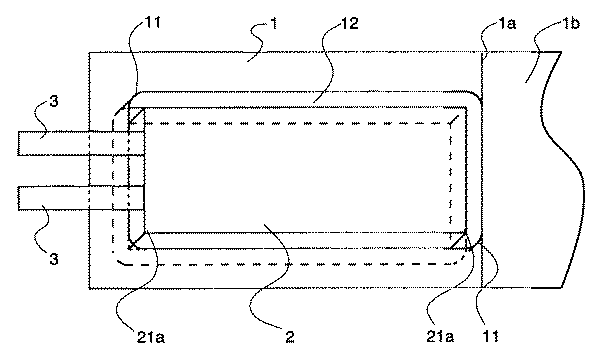
表1に示される結果から、本発明の効果が明らかである。具体的には、実施例1と比較例1との対比から、外装体の角アール半径が小さくなるとエッジ部への応力集中により、外装体アルミ箔にピンホールが空きやすくなり、微短絡不良数も多い。
【0078】
次に、実施例1と比較例3との対比から、同一の外装体に収まるように電極寸法を設定すると、角アールを有する実施例1のサンプルが実施例3のサンプルに比べ遙かにエネルギー密度が高く、徴短絡不良数も少ない。また、角アールなしで作製した比較例3では、外装体内に積層体(電池素体)は収容することができない。
【0079】
すなわち、外装体と電極の角アール半径を本発明で限定する範囲内にあるサンプルでは、体積エネルギー密度が高く、微短絡不良の少ない薄型電池が得られることが解る。
【0080】
【発明の効果】
以上のように、本発明によれば、アルミラミネート外装体を有する電気化学デバイスにおいて、高エネルギー密度で、かつ、外装体に挿入する際に生じる剥離やクラックによる微短絡を防止し、生産効率の高い電気化学デバイスを提供することができる。
【図面の簡単な説明】
【図1】本発明の電気化学デバイスの構成例を示す斜視図である。
【図2】従来の電気化学デバイスの構成例を示す斜視図である。
【符号の説明】
1 外装体
11 角部
2 セパレータ
21 角部
3 引き出し電極[0001]
[Technical field to which the invention belongs]
The present invention relates to sealing of electrochemical devices such as lithium secondary batteries and electric double layer capacitors.
[0002]
[Prior art]
With the remarkable development of portable devices in recent years, the importance of batteries used as power sources for portable devices, particularly lithium ion batteries, is rapidly increasing. In addition, with the increase in functions of mobile devices, higher energy and the accompanying improvements in battery characteristics and improvements in safety are the goals of technological development.
[0003]
As a measure therefor, there is an attempt to solidify the electrolyte. However, in terms of battery characteristics, there is a fundamental technical problem, for example, that it cannot be used at room temperature, so that practical application is extremely difficult.
[0004]
Therefore, in recent years, the focus has shifted to the development of a battery using a gelled electrolyte that improves characteristics of the liquid system while obtaining characteristics close to those of the liquid battery. In the case of this gelled battery, since there is no electrolytic solution liberated at room temperature as compared with the liquid battery and the amount of the liquid is small, an effect is also obtained for safety.
[0005]
Currently, lithium ion secondary batteries are classified into the following three types.
(1) A liquid battery using an electrolytic solution.
(2) A solid electrolyte battery using a gelled solid electrolyte made of an electrolytic solution and a polymer.
(3) A solid electrolyte battery having an electrolyte using lithium ion conduction in a solid of an inorganic material or an organic material.
[0006]
Here, the battery using the gelled electrolyte corresponding to (2) can contribute in terms of safety as described above.
[0007]
On the other hand, in order to differentiate these batteries from those using conventional metal cases, attempts have been made to reduce weight and thickness simultaneously, and in particular, exterior bodies using aluminum foil have been used. Can be made thinner and thinner.
[0008]
Such a battery using an aluminum foil as an exterior body is disclosed in, for example, Japanese Patent Application Laid-Open No. 2000-195476.
[0009]
As a background for the demand for such a thin battery, there is an increase in capacity and energy density of the battery. When increasing the capacity, it goes without saying that the volume of the battery inserted therein must be as large as possible. In addition, due to the need for product miniaturization, the battery shape has been required to be further reduced from a cylindrical shape to a rectangular shape.
[0010]
However, conventional batteries using a metal case such as aluminum wind up the positive electrode material, the negative electrode material, and the separator so that they are flattened and inserted. It was.
[0011]
In addition, thin deep-drawn type exterior bodies are molded from an aluminum laminate film material, so it is necessary to avoid cracks in the aluminum foil at the edges of the aluminum laminate exterior body. And a gap is also formed in this part.
[0012]
FIG. 2 shows a state in which the electrochemical device body is housed in such a conventional deep-drawing type exterior body.
[0013]
In the figure, the electrochemical device has an outer package 1 and an
[0014]
The
[0015]
That is, a film-like or sheet-like positive electrode material and negative electrode material are very brittle, and peeling or cracking from the current collector is likely to occur due to impact or the like. In particular, a battery using a separator has a problem that a peeled positive electrode material or negative electrode material penetrates the separator and causes a fine short-circuit phenomenon. In particular, the edge portion was liable to be peeled off or cracked from the current collector due to handling or the like. Conventionally, it has been necessary to cope with an increase in the amount of the binder of the positive electrode material and the negative electrode material, which has been one of the factors that decrease the energy density.
[0016]
[Problems to be solved by the invention]
An object of the present invention is to provide an electrochemical device having an aluminum laminate outer package, which has a high energy density and prevents a fine short circuit due to peeling or cracking that occurs when inserted into the outer package, and has a high production efficiency. Is to provide.
[0017]
[Means for Solving the Problems]
That is, the above object is achieved by the following configuration of the present invention.
(1) An electrochemical device having an aluminum laminate film as an exterior body and enclosing an electrochemical device body therein, wherein corners of the electrochemical device body are rounded, and the electrochemical The corners of the exterior body corresponding to the corners of the device body are also rounded,
R ′ ≦ R and 3.0 mm ≧ R ′ ≧ 1.0 mm and R−R ′ ≦ when the radius of radius of the corner of the electrochemical device body is R and the radius of radius of the corner of the outer package is R ′. Electrochemical device satisfying 2mm .
(2) The electrochemical device according to (1), wherein the outer package is deep-drawn.
(3) The electrochemical device according to the above (1) or (2) having a solid electrolyte.
(4) The electrochemical device according to any one of (1) to (3), which is a lithium secondary battery.
[0018]
[Action]
As a result of studying a structure that does not have such a useless space and improves the production efficiency, the present inventors have found a method for producing an electrochemical device that has a higher energy density and higher production efficiency than the conventional one. . In particular, the present inventors have found that this can be realized by setting a radius corresponding to the shape of the outer package to a predetermined range at the corner of the sheet-like or film-like positive electrode material or negative electrode material.
[0019]
By the way, in Japanese Patent Laid-Open No. 2000-208110, a flat battery in which a laminated electrode can be accommodated in an exterior case made of a laminate sheet mainly made of a resin film without creating a useless space and the outer dimensions of the battery are made compact is produced. It is described to do. This battery manufacturing method is similar to the electrochemical device of the present invention in that the laminated electrode is accommodated in an exterior body made of a laminate film without wasted space. However, there is no description about the electrode shape of the present invention.
[0020]
DETAILED DESCRIPTION OF THE INVENTION
The electrochemical device of the present invention is an electrochemical device having an aluminum laminate film as an exterior body and enclosing the electrochemical device body therein, and the corners of the electrochemical device body are rounded. It is what. Here, being formed in a round shape means that the corner portion is formed so as to draw a curve having a curvature radius R.
[0021]
Thus, by giving R to the corners of the electrochemical element sealed inside the exterior body of the electrochemical device, the electrochemical device body can be stored without waste in the internal space of the exterior body, A high energy density electrochemical device is obtained.
[0022]
In addition, since the corners of the electrochemical device body are processed to R, peeling and cracking do not occur during handling, especially when inserted into the exterior body, and a fine short-circuit phenomenon can be prevented. Efficiency is improved.
[0023]
The R formed at the corner of the electrochemical device body, that is, at the edge, may be efficiently stored in the storage space of the exterior body, and may be formed with a curvature that does not cause peeling or cracking. .
[0024]
Specifically, the radius R is preferably 0.5 mm ≦ R ≦ 10 mm.
More preferably 2mm ≦ R ≦ 4mm
Degree.
[0025]
Moreover, it is preferable that the corner | angular part R of an electrochemical device body is larger than or equal to the radius R 'formed in the corner | angular part of the exterior body to accommodate, and it is preferable to set it as the especially similar radius. When R is larger than R ′, the difference is preferably within 2 mm, particularly within 1 mm. Note that the rounded corners do not necessarily have an arc shape, and may be a curve that falls within the above range when approximated to a circular radius.
[0026]
The specific structural example of the electrochemical device of this invention is demonstrated based on figures. FIG. 1 is a schematic perspective view showing a state in which an exterior body of the electrochemical device of the present invention is developed.
[0027]
In the figure, the electrochemical device has an outer package 1 and an
[0028]
And the corner |
[0029]
The
[0030]
The electrochemical device body of the present invention has a structure in which positive and negative electrodes made of metal foil such as aluminum foil and copper foil and separators are alternately stacked. External electrodes (lead-out terminals) are connected to the positive and negative electrodes, respectively. The external electrode is made of a metal foil such as aluminum, copper, nickel, and stainless steel, a punching metal, and an expanded metal. In this case, if the corner portion of the overall electrochemical device base is may be formed in are the corners of at least the electrode may be formed on are.
[0031]
The electrochemical device used in the electrochemical device of the present invention is not limited to a battery such as a lithium secondary battery, and a capacitor having a similar structure can be used.
[0032]
The electrochemical device of the present invention can be used as the following lithium secondary battery and electric double layer capacitor.
[0033]
<Lithium secondary battery>
The structure of the lithium secondary battery is not particularly limited, but is usually composed of a positive electrode, a negative electrode, and a separator, and is applied to a stacked battery, a cylindrical battery, and the like.
[0034]
A gel type polymer may be used for the separator. For example,
(1) Polyalkylene oxides such as polyethylene oxide and polypropylene oxide,
(2) a copolymer of ethylene oxide and acrylate,
(3) a copolymer of ethylene oxide and glycyl ether,
(4) a copolymer of ethylene oxide, glycyl ether and allyl glycyl ether,
(5) Polyacrylate (6) Polyacrylonitrile (7) Polyvinylidene fluoride, vinylidene fluoride-hexafluoropropylene copolymer, vinylidene fluoride-trichloroethylene copolymer, vinylidene fluoride-hexafluoropropylene fluorine Examples thereof include fluoropolymers such as rubber and vinylidene fluoride “tetrafluoroethylene-hexafluoropropylene fluororubber”.
[0035]
The gel polymer may be mixed with an electrolytic solution, or may be applied to a separator or an electrode. Furthermore, the gel polymer may be cross-linked by ultraviolet rays, EB, heating or the like by adding an initiator.
[0036]
The electrode combined with the electrolyte may be appropriately selected from known ones as electrodes for lithium secondary batteries, and preferably a composition of an electrode active material and a gel electrolyte and, if necessary, a conductive aid is used.
[0037]
Moreover, the separator described in Unexamined-Japanese-Patent No. 9-219184, Unexamined-Japanese-Patent No. 2000-223107, and Unexamined-Japanese-Patent No. 2000-1000040 can also be used.
[0038]
The negative electrode uses a negative electrode active material such as a carbon material, lithium metal, lithium alloy or oxide material, and the positive electrode such as an oxide or carbon material capable of intercalating / deintercalating lithium ions. It is preferable to use a positive electrode active material. By using such an electrode, a lithium secondary battery having good characteristics can be obtained.
[0039]
The carbon material used as the electrode active material may be appropriately selected from, for example, mesocarbon microbeads (MCMB), natural or artificial graphite, resin-fired carbon material, carbon black, carbon fiber, and the like. These are used as powders. Of these, graphite is preferable, and the average particle size is preferably 1 to 30 μm, particularly preferably 5 to 25 μm. When the average particle size is too small, the charge / discharge cycle life is shortened and the capacity variation (individual difference) tends to increase. When the average particle diameter is too large, the variation in capacity becomes remarkably large and the average capacity becomes small. The reason why the variation in capacity occurs when the average particle size is large is thought to be because the contact between graphite and the current collector or the contact between graphites varies.
[0040]
The oxide capable of intercalating and deintercalating lithium ions is preferably a composite oxide containing lithium, and examples thereof include LiCoO 2 , LiMn 2 O 4 , LiNiO 2 , and LiV 2 O 4 . The average particle diameter of these oxide powders is preferably about 1 to 40 μm.
[0041]
If necessary, a conductive additive is added to the electrode. Preferred examples of the conductive aid include metals such as graphite, carbon black, carbon fiber, nickel, aluminum, copper, and silver, and graphite and carbon black are particularly preferable.
[0042]
The electrode composition is preferably in the range of active material: conducting aid: binder = 80 to 94: 2 to 8: 2 to 18 in the weight ratio for the positive electrode, and active material: conducting aid: binding in the weight ratio for the negative electrode. Adhesive = 70 to 97: 0 to 25: 3 to 10 is preferable.
[0043]
As the binder, a thermoplastic resin such as a fluorine resin, a polyolefin resin, a styrene resin, or an acrylic resin, or a rubber resin such as fluorine rubber can be used. Specific examples include polytetrafluoroethylene, polyvinylidene fluoride, polyethylene, polyacrylonitrile, nitrile rubber, polybutadiene, butylene rubber, polystyrene, styrene-butadiene rubber, polysulfide rubber, nitrocellulose, cyanoethyl cellulose, carboxymethyl cellulose, and the like.
[0044]
In producing the electrode, first, an active material and, if necessary, a conductive additive are dispersed in a binder solution to prepare a coating solution.
[0045]
And this electrode coating liquid is apply | coated to a collector. The means for applying is not particularly limited, and may be appropriately determined according to the material and shape of the current collector. In general, a metal mask printing method, an electrostatic coating method, a dip coating method, a spray coating method, a roll coating method, a doctor blade method, a gravure coating method, a screen printing method and the like are used. Then, if necessary, a rolling process is performed using a flat plate press, a calendar roll, or the like.
[0046]
The current collector may be appropriately selected from ordinary current collectors according to the shape of the device used by the battery, the method of arranging the current collector in the case, and the like. Generally, aluminum or the like is used for the positive electrode, and copper, nickel, or the like is used for the negative electrode. In addition, a metal foil, a metal mesh, etc. are normally used for a collector. The metal mesh has a smaller contact resistance with the electrode than the metal foil, but a sufficiently small contact resistance can be obtained even with the metal foil.
[0047]
Then, the solvent is evaporated to produce an electrode. The coating thickness is preferably about 50 to 400 μm.
[0048]
Such a positive electrode, a separator, and a negative electrode are laminated in this order, and pressed to form a battery body.
[0049]
The electrolytic solution impregnated in the separator generally comprises an electrolyte salt and a solvent. As the electrolyte salt, for example, a lithium salt such as LiBF 4 , LiPF 6 , LiAsF 6 , LiSO 3 CF 3 , LiClO 4 , LiN (SO 2 CF 3 ) 2 can be applied.
[0050]
The solvent of the electrolytic solution is not particularly limited as long as it has good compatibility with the above-described solid polymer electrolyte and electrolyte salt, but a polar organic solvent that does not decompose even at a high operating voltage in a lithium battery, for example, , Ethylene carbonate (abbreviation EC), propylene carbonate (abbreviation PC), butylene carbonate, dimethyl carbonate (abbreviation DMC), carbonates such as diethyl carbonate and ethyl methyl carbonate, cyclic ethers such as tetrahydrofuran (THF) and 2-methyltetrahydrofuran Cyclic ethers such as 1,3-dioxolane and 4-methyldioxolane, lactones such as γ-butyrolactone, sulfolane and the like are preferably used. 3-methylsulfolane, dimethoxyethane, diethoxyethane, ethoxymethoxyethane, ethyl diglyme and the like may be used.
[0051]
The concentration of the electrolyte salt when it is considered that the electrolytic solution is composed of the solvent and the electrolyte salt is preferably 0.3 to 5 mol / l. Usually, the highest ion conductivity is shown around 0.8 to 1.5 mol / l.
[0052]
<Electric double layer capacitor>
The structure of the electric double layer capacitor used in the present invention is not particularly limited. Usually, a pair of polarizable electrodes are arranged via a separator, and an insulating gasket is preferably provided around the polarizable electrode and the separator. Has been placed. Such an electric double layer capacitor may be any of a paper type, a multilayer type, and the like.
[0053]
As a polarizable electrode, activated carbon, activated carbon fiber, or the like is used as a conductive active material, and a fluororesin, fluororubber, or the like is added as a binder. And it is preferable to use what formed this mixture in the sheet-like electrode. The amount of the binder is about 5 to 15% by mass. A gel electrolyte may be used as the binder.
[0054]
The current collector used for the polarizable electrode may be a conductive rubber such as platinum or conductive butyl rubber, or may be formed by thermal spraying of a metal such as aluminum or nickel. A mesh may be attached.
[0055]
The electric double layer capacitor is combined with a polarizable electrode and a separator as described above.
[0056]
Examples of the electrolyte salt include (C 2 H 5 ) 4 NBF 4 , (C 2 H 5 ) 3 CH 3 NBF 4 , (C 2 H 5 ) 4 PBF 4, and the like.
[0057]
The non-aqueous solvent used in the electrolytic solution may be various known ones, and is an electrochemically stable non-aqueous solvent such as propylene carbonate, ethylene carbonate, γ-butyrolactone, acetonitrile, dimethylformamide, 1,2-dimethoxy. Ethane, sulfolane alone or a mixed solvent is preferred.
[0058]
The concentration of the electrolyte in such a nonaqueous solvent electrolyte solution may be 0.1 to 3 mol / l.
[0059]
When a microporous polymer film is immersed in such an electrolyte solution, the polymer film absorbs the electrolyte solution and gels to form a solid polymer electrolyte.
[0060]
When the composition of the polymer solid electrolyte is represented by a copolymer / electrolytic solution, the ratio of the electrolytic solution is preferably 40 to 90% by mass from the viewpoint of the strength of the membrane and the ionic conductivity.
[0061]
An insulating material such as polypropylene or butyl rubber may be used as the insulating gasket.
[0062]
The exterior body is composed of a laminate film in which a polyolefin resin layer such as polypropylene or polyethylene as a heat-adhesive resin layer or a heat-resistant polyester resin layer is laminated on both surfaces of a metal layer such as aluminum. The exterior bag is formed in a bag shape in which two laminated films are bonded in advance to each other by thermally bonding the heat-adhesive resin layers on the end surfaces of the three sides to form a first seal portion. Alternatively, a single laminate film may be folded and the end faces of both sides may be thermally bonded to form a seal portion to form a bag.
[0063]
As a laminate film, a laminate film having a laminated structure of a heat-adhesive resin layer / polyester resin layer / metal foil / polyester resin layer from the interior side is used to ensure insulation between the metal foil constituting the laminate film and the lead-out terminal. It is preferable to use it. By using such a laminate film, the polyester resin layer having a high melting point remains undissolved at the time of thermal bonding, so that a separation distance between the lead-out terminal and the metal foil of the outer bag can be secured and insulation can be secured. Therefore, the thickness of the polyester resin layer of the laminate film is preferably about 5 to 100 μm.
[0064]
The outer package is particularly preferably formed by deep drawing. By deep-drawing, a corner that accommodates the electrochemical device is formed in R.
[0065]
【Example】
Example 1
The following lithium secondary battery samples were produced.
(1) Molding of the outer packaging A laminated film with an aluminum foil (thickness 40 μm) placed between a heat-resistant nylon film (thickness 25 μm) and a heat-sealable polypropylene film is squeezed to less than 4 mm in size and about Molded to 35 × 55 mm. Particularly in this embodiment, the corner radius is 3 mm.
[0066]
(2) Production of electrode and solid electrolyte For the positive electrode, commercially available LiCoO 2 , carbon black as a conductive additive, and fluorine resin as a binder were mixed, and a slurry was prepared using a polar solvent. This was applied to an aluminum foil of a current collector, dried and rolled, and the current collector terminal portion was punched out to 33.5 × 50.5 mm to obtain a positive electrode. In particular, in this example, the punching dimension was set at an angular radius of 3 mm similar to the angular radius of 3 mm of the exterior body.
[0067]
As for the negative electrode, commercially available MCF and graphite, carbon black as a conductive auxiliary agent, and fluorine resin as a binder were mixed, and a slurry was prepared using a polar solvent. This was applied to a copper foil of a current collector, dried and rolled, and the current collector terminal portion was punched into a 34 × 51 mm except for a negative electrode. In particular, in this example, the punching dimension was set at an angular radius of 3 mm similar to the angular radius of 3 mm of the exterior body.
[0068]
As for the solid electrolyte, silicon dioxide and a fluorine-based resin were mixed, and a slurry was prepared using a polar solvent and a non-solvent for a porous agent. This was applied to a polyethylene terephthalate film, dried, punched out to 34 × 52, and peeled to obtain a solid electrolyte.
[0069]
(3) Battery fabrication method The electrode prepared above and a solid electrolyte are thermocompression-bonded, and a current collecting lead terminal coated with a heat-welding resin is welded to the current collecting terminal portion, and then accommodated in an aluminum laminate outer package and an electrolyte solution Was impregnated and sealed by heat sealing to obtain a thin battery sample. Note that the electrolytic solution, ethylene carbonate: diethyl carbonate = 4: 6 LiPF 6 in a mixed solvent is (volume ratio) was used at a concentration of 1M.
[0070]
(Example 2)
The corner radius of the outer package was set to 1 mm, and the corner radius of the positive electrode and the negative electrode was set to 1 mm. Other than this, a thin battery sample was obtained in the same manner as in Example 1.
[0071]
Example 3
The square radius of the positive electrode and negative electrode was set to 5 mm. Other than this, a thin battery sample was obtained in the same manner as in Example 1.
[0072]
(Comparative Example 1)
The corner radius of the outer package was set to 0.5 mm, and the corner radius of the positive electrode and the negative electrode was set to 0.5 mm. Other than this, a thin battery sample was obtained in the same manner as in Example 1.
[0073]
(Comparative Example 2)
The angular radius of the positive electrode and negative electrode was set to 0 mm. Other than this, a thin battery sample was obtained in the same manner as in Example 1.
[0074]
(Comparative Example 3)
The square radius of the positive and negative electrodes is set to 0 mm, the vertical and horizontal dimensions are reduced by 2 mm so that each corner is within the electrode dimensions of Example 1, the positive electrode dimensions are 31.5 × 48.5 mm, and the negative electrode The dimension was set to 32 × 49 mm. Other than this, a thin battery sample was obtained in the same manner as in Example 1.
[0075]
Table 1 shows the number of aluminum foil pinholes generated at the time of molding the exterior body, the number of micro short-circuit defects after the battery was created, and the 0.5C discharge capacity of each battery sample described above. In addition, the fine short circuit defect was defined as a battery that had a voltage drop of 50 mV or more when each battery sample was charged to about 3.7 V and left for one week.
[0076]
[Table 1]
From the results shown in Table 1, the effect of the present invention is clear. Specifically, from the comparison between Example 1 and Comparative Example 1, when the corner radius radius of the exterior body becomes small, the stress concentration on the edge portion makes it easy to make pinholes in the exterior body aluminum foil, and the number of micro short-circuit defects There are many.
[0078]
Next, from the comparison between Example 1 and Comparative Example 3, when the electrode dimensions are set so as to fit in the same exterior body, the sample of Example 1 having a square radius is much more energy than the sample of Example 3. High density and few short circuit defects. Moreover, in the comparative example 3 produced without the corner | angular round, a laminated body (battery element | base_body) cannot be accommodated in an exterior body.
[0079]
That is, it can be seen that a thin battery having a high volumetric energy density and few poor short-circuit defects can be obtained with a sample in which the angular radius of the outer package and the electrode is within the range defined by the present invention.
[0080]
【The invention's effect】
As described above, according to the present invention, in an electrochemical device having an aluminum laminate outer package, a high energy density and a fine short circuit due to peeling and cracks that occur when inserted into the outer package are prevented, and production efficiency is improved. A high electrochemical device can be provided.
[Brief description of the drawings]
FIG. 1 is a perspective view showing a configuration example of an electrochemical device of the present invention.
FIG. 2 is a perspective view showing a configuration example of a conventional electrochemical device.
[Explanation of symbols]
DESCRIPTION OF SYMBOLS 1
Claims (4)
前記電気化学デバイス素体の角部がアールに形成されており、
前記電気化学デバイス素体の角部に対応する、前記外装体の角部もアールに形成されており、
前記電気化学デバイス素体の角部のアール半径をRとし、前記外装体の角部のアール半径をR’とした時にR’≦Rかつ3.0mm≧R’≧1.0mmかつR−R’≦2mmを満たす電気化学デバイス。An electrochemical device having an aluminum laminate film as an exterior body and enclosing an electrochemical device element inside,
The corners of the electrochemical device body are rounded,
Corresponding to the corners of the electrochemical device body, the corners of the exterior body are also rounded,
R ′ ≦ R and 3.0 mm ≧ R ′ ≧ 1.0 mm and R−R , where R is the radius of curvature of the corner of the electrochemical device body and R ′ is the radius of curvature of the corner of the exterior body. 'An electrochemical device that satisfies ≤ 2 mm .
Priority Applications (1)
| Application Number | Priority Date | Filing Date | Title |
|---|---|---|---|
| JP2001054330A JP3822445B2 (en) | 2001-02-28 | 2001-02-28 | Electrochemical devices |
Applications Claiming Priority (1)
| Application Number | Priority Date | Filing Date | Title |
|---|---|---|---|
| JP2001054330A JP3822445B2 (en) | 2001-02-28 | 2001-02-28 | Electrochemical devices |
Publications (2)
| Publication Number | Publication Date |
|---|---|
| JP2002260600A JP2002260600A (en) | 2002-09-13 |
| JP3822445B2 true JP3822445B2 (en) | 2006-09-20 |
Family
ID=18914680
Family Applications (1)
| Application Number | Title | Priority Date | Filing Date |
|---|---|---|---|
| JP2001054330A Expired - Lifetime JP3822445B2 (en) | 2001-02-28 | 2001-02-28 | Electrochemical devices |
Country Status (1)
| Country | Link |
|---|---|
| JP (1) | JP3822445B2 (en) |
Cited By (1)
| Publication number | Priority date | Publication date | Assignee | Title |
|---|---|---|---|---|
| KR20170091938A (en) * | 2016-02-02 | 2017-08-10 | 주식회사 엘지화학 | Secondary Battery Cell Case Having Round Edge and Apparatus for Manufacturing the Same |
Families Citing this family (23)
| Publication number | Priority date | Publication date | Assignee | Title |
|---|---|---|---|---|
| JP4318967B2 (en) * | 2003-06-16 | 2009-08-26 | Tdk株式会社 | IC card |
| WO2005074054A1 (en) * | 2004-01-30 | 2005-08-11 | Lg Chem, Ltd. | Battery having specific package structure |
| WO2012131801A1 (en) | 2011-03-31 | 2012-10-04 | Necエナジーデバイス株式会社 | Battery pack |
| JP5761742B2 (en) * | 2011-03-31 | 2015-08-12 | Necエナジーデバイス株式会社 | Battery pack |
| WO2013047226A1 (en) * | 2011-09-28 | 2013-04-04 | Necエナジーデバイス株式会社 | Layered battery sealed with film-shaped outer covering material |
| JP2013134881A (en) * | 2011-12-26 | 2013-07-08 | Toyota Industries Corp | Power storage device and power storage device mounting vehicle |
| JP2013140825A (en) * | 2011-12-28 | 2013-07-18 | Asahi Kasei Corp | Laminate type electrical storage element |
| KR20130092791A (en) * | 2012-02-13 | 2013-08-21 | 에스케이이노베이션 주식회사 | Battery cell |
| US20130236768A1 (en) | 2012-03-08 | 2013-09-12 | Lg Chem, Ltd. | Battery pack of stair-like structure |
| KR20130105271A (en) | 2012-03-16 | 2013-09-25 | 주식회사 엘지화학 | Battery cell of asymmetric structure and battery pack employed with the same |
| KR20130113301A (en) | 2012-04-05 | 2013-10-15 | 주식회사 엘지화학 | Battery cell of stair-like structure |
| KR20130133640A (en) | 2012-05-29 | 2013-12-09 | 주식회사 엘지화학 | A stepwise electrode assembly having corner of various shape and a battery cell, battery pack and device comprising the same |
| KR101483505B1 (en) | 2012-11-13 | 2015-01-21 | 주식회사 엘지화학 | Stepped Electrode Assembly |
| US9484560B2 (en) | 2013-02-13 | 2016-11-01 | Lg Chem, Ltd. | Electric device having a round corner and including a secondary battery |
| US9786874B2 (en) | 2013-03-08 | 2017-10-10 | Lg Chem, Ltd. | Electrode having round corner |
| US9954203B2 (en) | 2013-03-08 | 2018-04-24 | Lg Chem, Ltd. | Stepped electrode group stack |
| KR101738734B1 (en) * | 2013-09-26 | 2017-06-08 | 주식회사 엘지화학 | Pouch type secondary battery |
| US10122010B2 (en) * | 2014-07-11 | 2018-11-06 | Semiconductor Energy Laboratory Co., Ltd. | Secondary battery and electronic device including the same |
| JP6135704B2 (en) * | 2015-03-30 | 2017-05-31 | 株式会社Gsユアサ | battery |
| WO2018134927A1 (en) * | 2017-01-18 | 2018-07-26 | 住友電気工業株式会社 | Bipolar plate, cell frame, cell stack, and redox flow cell |
| US10686213B2 (en) * | 2017-05-18 | 2020-06-16 | Panasonic Intellectual Property Management Co., Ltd. | Battery |
| JP2020027770A (en) * | 2018-08-14 | 2020-02-20 | 株式会社アルバック | Thin film lithium secondary battery and manufacturing method of thin film lithium secondary battery |
| CN109873092B (en) | 2019-02-26 | 2020-10-23 | 宁德新能源科技有限公司 | Battery unit and electronic device |
-
2001
- 2001-02-28 JP JP2001054330A patent/JP3822445B2/en not_active Expired - Lifetime
Cited By (2)
| Publication number | Priority date | Publication date | Assignee | Title |
|---|---|---|---|---|
| KR20170091938A (en) * | 2016-02-02 | 2017-08-10 | 주식회사 엘지화학 | Secondary Battery Cell Case Having Round Edge and Apparatus for Manufacturing the Same |
| KR102143366B1 (en) | 2016-02-02 | 2020-08-12 | 주식회사 엘지화학 | Secondary Battery Cell Case Having Round Edge and Apparatus for Manufacturing the Same |
Also Published As
| Publication number | Publication date |
|---|---|
| JP2002260600A (en) | 2002-09-13 |
Similar Documents
| Publication | Publication Date | Title |
|---|---|---|
| JP3822445B2 (en) | Electrochemical devices | |
| JP4293501B2 (en) | Electrochemical devices | |
| JP2000123873A (en) | Solid electrolyte battery | |
| JP2002298825A (en) | Method of producing electrochemical device and the electrochemical device | |
| JP4031635B2 (en) | Electrochemical devices | |
| JP2001118547A (en) | Package | |
| JP2002208384A (en) | Nonaqueous electrolyte battery and its manufacturing method | |
| WO2014050114A1 (en) | Non-aqueous electrolyte secondary battery | |
| JP2002270239A (en) | Electrochemical device | |
| JP4887634B2 (en) | Battery and its sealing method | |
| JP2000277066A5 (en) | ||
| JP2000133216A (en) | Nonaqueous electrolyte battery and manufacture of same | |
| JP2011187241A (en) | Nonaqueous electrolyte secondary battery | |
| JP4021592B2 (en) | Electrochemical devices | |
| JP4060549B2 (en) | Electrochemical element exterior | |
| JP4055345B2 (en) | Solid electrolyte battery | |
| JP4449214B2 (en) | Non-aqueous electrolyte battery | |
| JPH11260414A (en) | Nonaqueous system secondary battery | |
| JP2004349156A (en) | Secondary battery and stacked secondary battery | |
| JP4821043B2 (en) | Electrochemical devices | |
| JP4202549B2 (en) | Electrochemical device and manufacturing method thereof | |
| JP7372981B2 (en) | Electrochemical devices and electronic devices including electrochemical devices | |
| JP2000285902A5 (en) | ||
| JP4830295B2 (en) | Non-aqueous electrolyte secondary battery | |
| JPH06243856A (en) | Electricity accumulating element |
Legal Events
| Date | Code | Title | Description |
|---|---|---|---|
| RD04 | Notification of resignation of power of attorney |
Free format text: JAPANESE INTERMEDIATE CODE: A7424 Effective date: 20040531 |
|
| A621 | Written request for application examination |
Free format text: JAPANESE INTERMEDIATE CODE: A621 Effective date: 20050531 |
|
| RD02 | Notification of acceptance of power of attorney |
Free format text: JAPANESE INTERMEDIATE CODE: A7422 Effective date: 20050531 |
|
| RD03 | Notification of appointment of power of attorney |
Free format text: JAPANESE INTERMEDIATE CODE: A7423 Effective date: 20050531 |
|
| A521 | Written amendment |
Free format text: JAPANESE INTERMEDIATE CODE: A821 Effective date: 20050531 |
|
| A871 | Explanation of circumstances concerning accelerated examination |
Free format text: JAPANESE INTERMEDIATE CODE: A871 Effective date: 20051031 |
|
| A975 | Report on accelerated examination |
Free format text: JAPANESE INTERMEDIATE CODE: A971005 Effective date: 20051118 |
|
| A131 | Notification of reasons for refusal |
Free format text: JAPANESE INTERMEDIATE CODE: A131 Effective date: 20051129 |
|
| A521 | Written amendment |
Free format text: JAPANESE INTERMEDIATE CODE: A523 Effective date: 20060130 |
|
| A131 | Notification of reasons for refusal |
Free format text: JAPANESE INTERMEDIATE CODE: A131 Effective date: 20060328 |
|
| A521 | Written amendment |
Free format text: JAPANESE INTERMEDIATE CODE: A523 Effective date: 20060529 |
|
| TRDD | Decision of grant or rejection written | ||
| A01 | Written decision to grant a patent or to grant a registration (utility model) |
Free format text: JAPANESE INTERMEDIATE CODE: A01 Effective date: 20060620 |
|
| A61 | First payment of annual fees (during grant procedure) |
Free format text: JAPANESE INTERMEDIATE CODE: A61 Effective date: 20060622 |
|
| R150 | Certificate of patent or registration of utility model |
Free format text: JAPANESE INTERMEDIATE CODE: R150 Ref document number: 3822445 Country of ref document: JP Free format text: JAPANESE INTERMEDIATE CODE: R150 |
|
| FPAY | Renewal fee payment (event date is renewal date of database) |
Free format text: PAYMENT UNTIL: 20090630 Year of fee payment: 3 |
|
| FPAY | Renewal fee payment (event date is renewal date of database) |
Free format text: PAYMENT UNTIL: 20100630 Year of fee payment: 4 |
|
| FPAY | Renewal fee payment (event date is renewal date of database) |
Free format text: PAYMENT UNTIL: 20110630 Year of fee payment: 5 |
|
| FPAY | Renewal fee payment (event date is renewal date of database) |
Free format text: PAYMENT UNTIL: 20120630 Year of fee payment: 6 |
|
| FPAY | Renewal fee payment (event date is renewal date of database) |
Free format text: PAYMENT UNTIL: 20120630 Year of fee payment: 6 |
|
| FPAY | Renewal fee payment (event date is renewal date of database) |
Free format text: PAYMENT UNTIL: 20130630 Year of fee payment: 7 |
|
| FPAY | Renewal fee payment (event date is renewal date of database) |
Free format text: PAYMENT UNTIL: 20140630 Year of fee payment: 8 |
|
| EXPY | Cancellation because of completion of term |