JP3814652B2 - Magnetic flux switching linear motor - Google Patents
Magnetic flux switching linear motor Download PDFInfo
- Publication number
- JP3814652B2 JP3814652B2 JP2000616110A JP2000616110A JP3814652B2 JP 3814652 B2 JP3814652 B2 JP 3814652B2 JP 2000616110 A JP2000616110 A JP 2000616110A JP 2000616110 A JP2000616110 A JP 2000616110A JP 3814652 B2 JP3814652 B2 JP 3814652B2
- Authority
- JP
- Japan
- Prior art keywords
- magnetic flux
- magnetic
- linear motor
- flux switching
- stator
- Prior art date
- Legal status (The legal status is an assumption and is not a legal conclusion. Google has not performed a legal analysis and makes no representation as to the accuracy of the status listed.)
- Expired - Fee Related
Links
- 230000005291 magnetic effect Effects 0.000 title claims abstract description 108
- 230000004907 flux Effects 0.000 title claims description 64
- 239000000696 magnetic material Substances 0.000 claims abstract description 7
- 239000003302 ferromagnetic material Substances 0.000 claims description 3
- 238000004804 winding Methods 0.000 claims 8
- 230000005294 ferromagnetic effect Effects 0.000 claims 5
- 239000000463 material Substances 0.000 abstract description 2
- 238000005452 bending Methods 0.000 description 5
- 238000010586 diagram Methods 0.000 description 5
- 229910001209 Low-carbon steel Inorganic materials 0.000 description 3
- 238000009826 distribution Methods 0.000 description 3
- 229910052782 aluminium Inorganic materials 0.000 description 2
- XAGFODPZIPBFFR-UHFFFAOYSA-N aluminium Chemical compound [Al] XAGFODPZIPBFFR-UHFFFAOYSA-N 0.000 description 2
- 230000000694 effects Effects 0.000 description 2
- 238000004519 manufacturing process Methods 0.000 description 2
- 229920002994 synthetic fiber Polymers 0.000 description 2
- RYGMFSIKBFXOCR-UHFFFAOYSA-N Copper Chemical compound [Cu] RYGMFSIKBFXOCR-UHFFFAOYSA-N 0.000 description 1
- 230000005355 Hall effect Effects 0.000 description 1
- 230000006978 adaptation Effects 0.000 description 1
- 238000003491 array Methods 0.000 description 1
- 239000002131 composite material Substances 0.000 description 1
- 239000004020 conductor Substances 0.000 description 1
- 229910052802 copper Inorganic materials 0.000 description 1
- 239000010949 copper Substances 0.000 description 1
- 238000005520 cutting process Methods 0.000 description 1
- 230000003247 decreasing effect Effects 0.000 description 1
- 230000001627 detrimental effect Effects 0.000 description 1
- 230000009977 dual effect Effects 0.000 description 1
- 230000002045 lasting effect Effects 0.000 description 1
- 230000005415 magnetization Effects 0.000 description 1
- 239000002923 metal particle Substances 0.000 description 1
- 230000004048 modification Effects 0.000 description 1
- 238000012986 modification Methods 0.000 description 1
- 230000000737 periodic effect Effects 0.000 description 1
- 238000004904 shortening Methods 0.000 description 1
- 229910000859 α-Fe Inorganic materials 0.000 description 1
Images


Classifications
-
- H—ELECTRICITY
- H02—GENERATION; CONVERSION OR DISTRIBUTION OF ELECTRIC POWER
- H02K—DYNAMO-ELECTRIC MACHINES
- H02K41/00—Propulsion systems in which a rigid body is moved along a path due to dynamo-electric interaction between the body and a magnetic field travelling along the path
- H02K41/02—Linear motors; Sectional motors
- H02K41/03—Synchronous motors; Motors moving step by step; Reluctance motors
- H02K41/031—Synchronous motors; Motors moving step by step; Reluctance motors of the permanent magnet type
Abstract
Description
【0001】
本発明は、各々が移動磁極を規定する磁気電機子(magnetic armature)をとり囲む少なくとも2つの界磁コイル及び反対極性に磁化された2つの永久磁石を含む移動リグ(moving rig)と、この移動リグの移動中上記の移動磁極に連続的に順次対面するような形で固定子管(stator tube)の少なくとも1つの壁の上でその固定子管に沿って配置されている磁極を示すガイド固定子管(guidance stator tube)、及びコイルの電流の方向を切換えるための手段から成る、少なくとも2相を有する磁束切換え形リニアモータ(flux-switching linear motor)に関する。
【0002】
公知のリニアモータの大部分は、レールにより支持される1列又は2列の永久磁石を通過して走行する幾つかのコイルを含む移動リグで構成されている。かかるモータについては、例えば特許出願第EP0 161 677号に記述されている。このモータにおいては、磁石は、例えばアルミニウム製の非磁性部材の内側面の1つの全体に沿って交番する磁極を有して配置されており、この一連の磁石が周期的構造の間隔を規定している。その最も単純な形態においては、上記の移動リグは、上記の部材の対向する内側面上に配置された2つのトラックにより切換えられる、そのコイルの直流電流供給用の接触子(wiper)が取り付けられた2つのコイルで構成されている。このコイルは、4分の1間隔だけオフセットされ、直角位相(phase quadrature)で電流が供給される。もう1つの実施例によれば、移動リグは、3分の1間隔だけオフセットされ、120°オフセットされた電流で供給される3つのコイルから成る。
【0003】
もう1つの実施例は、特許出願GB2 233 835の中で記述されている。この実施例においては、3つのコイルから成る移動リグは、U字側面を有する部材(U-profile member)の対称面内に配置された固定型磁石とオーバラップする。
【0004】
従ってこれらの構造は、移動リグの経路全長にわたり磁石を必要とするが、ある任意の瞬間において活動状態にあるのはそのうちの一部だけである。高性能磁石が使用される場合、かかる設備のコストは相当高くなり、設備の長さが大きくなればなるほどなおさら受入れ難いものとなる。フェライトを使用すると、このコストは許容できるものとなるが、その代償として性能は凡庸なものとなる。その上、現場での調節(adaptation)が必要な場合、リニアレールを切って単に長さを短縮するだけで済む作業が、磁石を予め分解し、作業後にレール全体を入念に掃除をすることを必要とする複雑な作業となる。もう1つの欠点は、モータが産業環境内で運転している場合に現われる。つまりかかる環境において遭遇する金属粒子が磁石によりひきつけられて、モータの適切な運転を妨害することになる。
【0005】
特許EP0 667 991号で記述されているモータは、これらの欠点を除去するものである。移動リグが中を走行するガイド管はもはや磁石を含まず、それ自体強磁性材料で作られ、2つの対面する列内に配置された固定子磁極を表すような形で切断され、1つの列の磁極はもう1方の列の磁極に対して直線状にオフセットされている。移動リグの各相は、移動リグの走行方向に沿って磁化された、反対の極性の2つの永久磁石が間に配置されている3つの磁極片から成る電機子をとり囲む界磁コイルを含む。固定子磁極及び移動磁極は、電機子の2つの接合位置のうちの第1の位置で、各々が磁極片のそれぞれの一方に属する2つの第1の移動磁極が、2つの異なる固定子磁極列に属する2つの固定子磁極と一致し、一方その他の2つの移動磁極が固定子磁極に関してオフセットされており、一方第2の接合位置ではその他の2つの移動磁極が順次に固定子磁極と一致し、第1の2つの移動磁極が、順次に固定子磁極に関してオフセットされるような形で、配置されている。
【0006】
かかるモータは、固定磁石を含まないという利点を有するものの、固定子の管状形状のために、ギャップのサイズを縮小するのに必要とされる精度に関するかぎりにおいては、その製造が複雑になる。その上、被駆動体に対して移動リグを機械的にリンクさせるには、固定子管がその長さ全体にわたりその1方の側面で分割される必要があり、このことがその磁気効率(magnetic efficiency)を妨げている。その上、電機子の磁極片に印加される負荷は非対称であり、そのため、移動リグ上に1つ又はそれより多いねじりトルク(torsional couple)が生じる。この欠点のため、構造を著しく剛性化しかつ/又はギャップを増大させることが不可欠となる。さらに、移動リグと固定子管の未切断側面の間に存在する磁気漏洩がモーターの性能を劣化させるということも注意が必要である。最後に、固定子管は、曲率半径が大きい場合であっても、直接的アクチュエータ(direct actuator)を作り出すのに必要とされる曲げ加工作業と相容れない。
【0007】
本発明の目的は、上述の欠点を除去すること、すなわち、固定子の磁気効率を増大させ、磁気漏洩を低減させ、ガイド固定子管を曲げ加工して曲線を作り出すことを可能にすることにある。
【0008】
本発明に従ったリニアモータは、永久磁石が移動リグのコイルの外側に配置されていること、及びそれらがコイルの軸に対して平行な軸に沿って磁化されていること、及び固定子磁極が、非磁気材料で作られたガイド管(guidance tube)の中に固定された磁気材料で作られた部品片(piece)から成り、磁石の磁軸に沿って測定された磁石の寸法は、固定子磁極を通過する磁石の移動のための狭いギャップを作り出すような形で選択されていること、を特徴とする。
【0009】
固定子磁極片は好ましくは対を成して、ガイド管の軸の両側に配置されており、磁石の磁軸に沿って測定した永久磁石の寸法は、2つの対面する固定子磁極片を隔てる距離に対応する。この配置には、移動リグ上のねじりトルクを除去するという利点がある。
【0010】
本発明の2つの実施形態に従うと、反対の極性の磁石が、コイルの軸及び固定子管の方向に対する垂線を含む平面に関して対称(変形実施例1)か又はコイルの軸及び固定子管の軸を含む平面に関して対称(変形実施例2)に配置されている。
【0011】
ガイド管は、固定磁石を有するリニアモータの場合と同様にU字形部材で構成されることができ、それによって性能を損なうことなく被駆動体に対し移動リグを機械的にリンク(link)することが可能になる。移動リグ上にかかる負荷は、完全に対称であるのでねじりトルクはなくなる。その結果、移動リグをその移動中ガイド管内の中央位置に保つのに適度なガイドだけで充分である。その上、変形実施例1の場合においては、ボール及びソケット継手(socket joint)を介してかまたは単に直接接触状態にある交番磁石(alternating magnets)対の間のリンクを利用することによって2相又は3相が連接されるのを妨げるものは何もない。中央スタッドが作り出す2相間の適度のギャップにより、1方の相が他方の相に関して回転できるようになる。この場合、2つの隣接する磁界コイルは、極性が反対の2つの磁石によってリンクされる。
【0012】
簡単化された実施例に従うと、固定子磁極片は、ガイド固定子管の単一の壁上に配置されており、移動リグには、固定子磁極片と反対側上に磁気的短絡プレートが備わっている。このプレートの効果は、固定子磁極のイメージ(image)を作り出すことにある。
【0013】
隣接コイルは、共通磁石を共有することができる。3相構成に対しては、変形実施例1に従ってか又はその簡単化された実施例に従って、この場合2つの共通磁石は反対向きに分極される。
【0014】
全てのケースにおいて、磁界コイル内の電流の切換えは、先行技術、特に特許EP0 667 991号に記述されているように、交流又は直流電源によって達成することができる。切換えは、特許EP0 161 677号に記述されているように適切な形状の導電トラック(conducting track)によって達成することもできるし、又は、特許EP0 667 991に記述されているように移動リグ上に取り付けられた切換え装置(switching device)により達成することもできる。
【0015】
添付図面は、一例として、本発明に従ったモータのいくつかの実施形態を例によって表している。
【0016】
ここで図1〜3を参照する。
【0017】
ここで表されているモータは、例えばアルミニウム製の方形断面の非磁性U字形ガイド部材から成る固定子管1を含む。これは、例えば軟鋼といった強磁性材料から作られるパッド(pad)あるいは方形ラグ(rectangular lug)2から成る固定子磁極に対する支持体としての役割をするのみであるから、合成材料で作られてもよい。これらのパッド2は、U字形部材の2つの平行な対向する脚部の内部面に対し固定されるような形で、部材1内に形成された1対の対向する溝3、4内にしっかりと固定して係合させることによって保持される。パッド2は、対を成して位置決めされ、そのため1つの対の2つのパッドは、部材1の軸に関して対称的に互いに対面する形で置かれている。パッド2の連続した対は等間隔で置かれており、モータの間隔を規定する距離だけ間隔をあけられている。その横断壁内に、管1はさらに、以下で記述するように移動リグをガイドするための2つの付加的な溝5及び6を有する。これらの溝5及び6は、移動リグのスライドを容易にする材料でコーティングされることがある。
【0018】
移動リグは、図1〜3に表された相P1といったような2相又は3相を含み、これらの相の各々は原則として、固定子磁極2の平面に対し垂直な軸をもつコイル7から成り、このコイルは、電機子を構成する磁気材料で作られたコア8をとり囲んでいる。固定子管1の軸に沿ってコイル7の各側面に配置されているのは、コイルの軸に対し平行で反対向きに磁化された2つの永久磁石9及び10である。コイル7の2つの端部に固定されているのは、永久磁石9及び10の固定に共働する非磁気材料、好ましくは合成材料製の2つの方形フランジ11及び12である。コア8及び永久磁石9及び10は、固定子管1の軸に沿って見た場合実質的に同じ正方形の断面を示し、これらはこの軸に沿って心合せ(align)されている。側面から見ると、コア8及び磁石9及び10は、実施形態によりその幅が変りうる方形断面を示す。2相移動リグは、P1といったような相が2つ並置されて構成され、3相移動リグは、P1といったような相が3相並置されて構成される。
【0019】
図3からわかるように、移動リグは、溝5及び6の中をスライドするその2つのフランジ11及び12により管1の中でガイドされる。永久磁石9及び10又はコア8と固定子磁極2の間の距離が2つのギャップe1及びe2を規定する。
【0020】
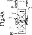
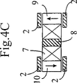
図4A−4Dは、本発明に従ったモータの原理を、その変形実施例1において例示している。
【0021】
図4Aに表された位置において、コア8は一対の固定子磁極2の間に位置し、その隣接する対は、永久磁石9及び10がこれらの隣接対の間で係合されないような距離のところに位置づけされている。2つの永久磁石9及び10の磁界は、コア8の隣接固定子磁極2を通り、そしてこのコア8を通って閉じる傾向をもつ。これら2つの磁界は等しくかつ反対向きであることから、コア8内の磁束はゼロである。
【0022】
図4Bに表されている位置にくるように移動リグが右方向に移動した場合、この位置ではコア8内の主磁束は固定子磁極2の近くの永久磁石10から生ずるということがわかる。この磁束は、小さな湾曲した矢印によって示されている第1の方向でコイル7を通過する。
【0023】
移動リグを右に向かってひきつづき移動させることにより、図4Cに表された位置に到達し、ここでコイル7は、2対の固定子磁極2の間の丁度中央に位置決めされ、永久磁石9は一対の2つの固定子磁極の間にあり、磁石10はそれに隣接する対の固定子磁極間にある。この位置で、コイル内の合成磁束(resultant flux)は再びゼロとなる。
【0024】
移動リグを右に向かってひきつづき移動させることにより、図4Dに表された位置に到達し、これは、図4Bに表された位置と対称の位置である。この位置で、主磁束は今度は磁石9から生じ、これは小さな湾曲した矢印によって示された方向に通る。この磁束は、図4Bの中で表されている位置での方向とは反対の方向にコア8を介してコイル7を通過する。
【0025】
従って、磁極片2間のコイルの移動により、交番起電力を得ることが可能となる。
【0026】
図4B中の磁石9の磁界及び図4D中の磁石10の磁界は、コア8内に磁気的損失(magnetic loss)を作る望ましくない磁束を生成する。しかしながら図4Bにおいて磁石9の磁極と一方ではコア8の端部との間そして主磁束が中を通る固定子磁極片2との間の距離は、比較的大きく、そのため、特許EP0 667 991号に従った構造において起こるものとは異なり、損失はきわめて小さい。対面する縁部が面取り(bevel)されたラグ(lug)を使用することにより、磁気損失をさらに制限することが可能である。
【0027】
図1〜3そして概略的には図4A〜4Dに表されているように、2つ又は3つの移動リグを並置することにより、それぞれ2相又は3相モータを製造することが可能となる。
【0028】
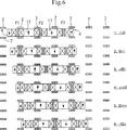
図5には、3相モータが概略的に表されている。これは、P1,P2及びP3の3相から成り、それらのコイルの軸は、それぞれ2つの続いた固定子磁極対間の距離により規定される固定子間隔に関して1/3及び2/3の間隔だけオフセットされている。2つの隣接するコイルの軸間距離は、従って、4/3の間隔に等しい。2相モータの場合は、コイルの軸は固定子間隔に関して1/4間隔だけそれぞれオフセットされることになろう。明らかに、これらのオフセットは、整数倍の間隔内に対して与えられ、単に関連するコイル内の電流を逆転させることにより、オフセットに2分の1間隔を加算するか又はオフセットから2分の1間隔を減算することが可能である。
【0029】
図5は、1/6間隔だけオフセットされた6つの位置の動的シーケンス(dynamic sequence)及び3相内の磁束の対応する分布を表している。各シーケンスの右に現われる+,−,0の符号は、電流が無い状態での各相のコア内の磁束の存在とその方向を表している。すなわち、例えば−/+/0は、相P1には、下向きの「負の」磁束が存在し、P2には上向きの「正の」磁束が存在し、又P3には磁束がゼロである、などを意味している。
【0030】
どのような直流機でも行なわれているように、コイル内の電流は、誘起起電力が消滅し方向を変える時点、すなわちこのコイル内の磁束がいずれかの方向で最大になる時点で反転させられる。特許第EP0 667 991号のように、各相は、固定子管1の底面内すなわち溝5と6の間に取り付けられた絶縁性支持体上にプリントされた銅製の給電トラック(supply track)上を走行する一対の接触子接点(wiper contact)を備えることができる。これらのトラックには直流電流が供給され、特許EP0 161 677号に示され記述されているような2つのトラックの入れ子式くぼみ(nested recess)の形の形状によって、切換えを達成することができる。また、特許EP0 667 991に記述され当業者にとっては既知であるように、2つの連続した真直ぐな導体レールを介してコイルに給電すること、そして移動リグの各相内に取り付けられた切換え装置を用いて切換えを達成することも同様に可能である。例えばMotorola社製のMC33033集積回路といったような、移動リグ上に直接取り付けられるホール効果センサの状態に基づいて、専用の電子回路によって、かかる制御が容易に可能となる。
【0031】
固定子管の構造だけで、管1を曲げ加工することによって曲がりを作り出すことができる。移動リグにおいては、図5に表されているモータの3相を、曲がりを容易に吸収できるような形で相互に連接してもよい。この連接部14は、ボール及びソケット継手を介してか又はきわめて単純に、1つの相の回転をその他の相に関して可能にする中央スタッドによって作り出される適度のギャップを2つの隣接する相の間に残すことによって、直接的接触状態にある交番磁石対の間の磁気的リンクを利用して実施することができる。
【0032】
移動リグを連接する必要がない場合には、図5と類似の要領のシーケンスを表す図6に示されたようにこれを簡単化することができる。この実施例においては、2相を相互にリンクする磁石9及び10は、その磁化方向がそれに最も近い外側の磁石の磁化方向とそれぞれ反対である共通の磁石13によって置き換えられており、その結果、図6から明らかであるように、磁石13の極性は互いに反対になっている。図5に表されている実施例の作用と同様な作用を回復させるためには、シーケンスの位置の各々について示された磁束分布から明らかになるように、相P2のコイルの接続を逆にしなければならない。共通磁石を有するこの配置により、直接隣接する逆の極性の磁石の間のかなり大きな漏洩磁束は防止されることは明白である。
【0033】
図1〜3に表された実施例においては、移動リグには明らかに、溝5及び6の中を走るローラを据えつけることができよう。
【0034】
本発明に従ったリニアモータの実用的な実施例には、その性能を最適化するのに適した変更が伴う。図7及び図8a〜eは、この場合前方から見た、ラグの平面に対し平行な平面内に、2相の移動リグを有する装置を示している。
【0035】
便宜上及び標準部品を使用するために、磁石9′はここでは円筒形であり、以前の長方形磁石の各々が、1つのケーシング15の中にかしめて取付けられた(crimped)一対の磁石によって置き換えられている。慣例により、黒い面はN極に対応するものとする。
【0036】
コイル7′も、そのコア8′と同様、円筒形であるが、進行に対して垂直な方向に細長いポールシュー(pole shoe)16が有利にも各コイル/コアのアセンブリのいずれかの側に配置されている。このポールシューは、ラグ2により伝達された磁束を収集することとケーシング15内にコイルを機械的に保持することという2重の機能を確保する。
【0037】
最後に、磁石及びコアの軸に対し平行にかつ同じ長さで、ある与えられた瞬間にコイルのコアと鎖交(linkage)する位置にない磁石の磁束の正しい通過(flow)を確保するよう意図して軟鋼磁気パッド17を配置することが、非常に有利である。磁石及びコイルと同様、これらのパッド17もケーシング15の中をまっすぐ貫通する。
【0038】
図8aは、初期位置にある固定子ラグ2の列に面する移動リグを表す。より容易に観察できるようにするため、ラグ2は、ここでは誇張した高さを有している。すなわち、それらは、磁石とオーバラップするだけで充分であり、余分な高さは全て、ラグからラグへの磁気漏洩の増大の形で現われる。
【0039】
移動リグのラグのそれぞれの位置関係のため、相P1のコイルには理想的には、その右側に位置するS極の磁石の磁束が完全に横切り、一方その左側に位置するN極の磁石の磁束は左端部のパッド17により閉じられている、ということがわかる。同じ瞬間では、相P2内の磁束はゼロである。
【0040】
すぐその後、図8bで、P1内の磁束は減少しており、一方P2の磁束は、その右側に位置するN極の磁石から生じて増大する。
【0041】
図8cの瞬間は、8aに関して4分の1間隔だけ磁気的にオフセットされており、このときP1で磁束はゼロであり、一方P2では磁束は最大である。以下同様。すなわちその直後に、P1の磁束は主にその左側に位置するN極の磁石から生ずる。
【0042】
構成要素のこの配置により、連結(conjunction)中に磁石とコアがオーバラップすること及び準ゼロ磁束(quasi-zero flux)の状況が過度に長く持続するのを防ぐことの両方が可能になるということがわかる。
【0043】
最後に、本特許中に記述された全ての実施例は、単一の固定子ラグ列2を有し、固定子ラグが省略されている側で移動リグにしっかり固定された磁気的短絡プレート又は磁束閉路プレート(flux closure plate)18を有する図9に表された簡略化された変形実施例に適合している。この配置は、特に曲げ加工時において製造がはるかに簡単であるという利点をもつ。一方、以前のように、負荷の平衡化ひいては特にキャスタを用いたより入念なガイドの必要性はもはやなくなる。磁気的観点から見ると、かかる磁気的短絡18は、ミラーの役割を果たすものとして知られている。全てが、あたかもなお2重の固定子ラグ列2が存在するかのように起こるが、しかし、イメージ・ラグ2′が破線で表されている図9bに示されているように、距離は移動リグの幅の少なくとも2倍になる。
【0044】
図10は、ここで、本発明の第2の変形実施例に従った移動リグを表している。同じ極性の磁石が、ここではコイルの軸と固定子管の軸により規定される平面の同じ側に配置されている。シートにより規定される方向を取るとき、以前はコイルの左又は右のいずれかに位置する磁石から発して平均的には水平に通っていた磁束は、今や、コイルの上又は下のいずれかに位置する磁石から発して平均的には垂直に通ることになる。以前のように、これはコア内の合成磁束の通過のいずれかの方向に有利に作用する固定子ラグの配置である。
【0045】
変形実施例2の原理は、2相の実施形態における直接的な例示となりうるという点で変形実施例1の原理に充分に近いものであるが、この場合は進行の方向において特にコンパクトなものである。図10において、2つの磁石9″,10″は、固定子間隔の4分の3だけ間隔をあけられている。コイルのコア8上にはポールシューは使用されない。ここでは円筒形状の2つの側面磁束閉路要素17が使用される。
【0046】
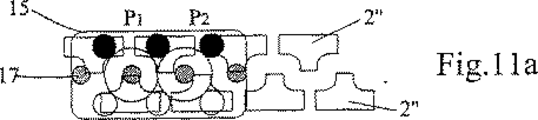
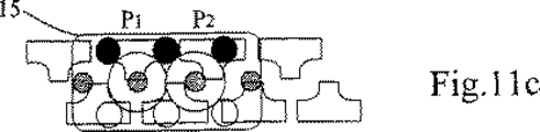
図11a〜11cは、固定子ラグ2″が存在する状態でのこの変形実施例2の作用の仕方を例示している。このラグ2″は、三角形状と同様と思われるような、ラグ間漏洩を最小化するT形の形状を有しており、ここでも、固定子管の軸を含みラグに平行な平面の両側で対称的に対を成して配置されている。ここでは、1間隔あたり2対の固定子ラグ2″が存在する。すなわちラグは2分の1間隔毎に交互に上向き及び下向きの方向に向けられる。
【0047】
移動リグ15及び固定子ラグ2″のそれぞれの位置関係のため、図11aで、相P1のコイルには理想的には、下に位置するS極の磁石の磁束が完全に横切り、一方上と左にあるN極の磁石の磁束は左端部の補助円筒17により部分的に閉じている、ということがわかる。同じ瞬間では、対称性のためとP2のコイルのコアがP2の左上及び右下に存在する磁石により短絡状態となる傾向を有するための両方の理由で、相P2内の磁束はゼロである。
【0048】
4分の1間隔後、図11bで、P1内の磁束はゼロとなり、一方P2の磁束は下に位置するS極の磁石から生じて最大である。
【0049】
図11cの瞬間は、11aに関係して2分の1間隔だけオフセットされており、このときP2で磁束はゼロであり、一方P1ではこのとき上に位置するN極の磁石から生じて、最大である。以下同様。
【0050】
変形実施例2は、連続した相の間での共通磁石の共用を可能にするということが観察されるだろう。限度内で、上面磁石及び底面磁石は、コイルの(図面の)上と下すなわち移動リグの走行方向を基準としたときコイルの各々の側に設置された2つの個々の長方形磁石でありうる。
【0051】
同様にして、原則としてこの変形実施例は、全ての(図面の)上部固定子ラグ及び全ての下部固定子ラグのリンク(link up)を可能にする。すなわち、このとき、使用される固定子面の各々の上に、入れ子式くし(nested comb)の形をした2つの部品片が存在することになろう。しかしながら、ラグのこのリンクはそれがもたらす磁気漏洩の著しい増大のため使用されない。
【0052】
最後に、変形実施例1と2に関する代替の変更、特に固定子部材の1面のみを使用するように移動リグの片面上に磁気的短絡を使用するといった変更を加えることも可能である。
【0053】
最後に、図12は、本発明にヒントを得た無数の実施形態のうちの1つを例示している。これは前出のケースの1変形実施例であるが、今度は、1つの同一対の固定子ラグ2″及び2'''は固定子管の軸に対し対称的である。固定子管の同じ面に属するラグ2″は、太線で表され、反対の相に属するラグ2'''は細線で表されている。より容易に観察できるようにするため、コイルはそのコア8によってのみ表されている。相P1は最大磁束の位置にある。一対の磁石の磁束がコアを通過し、次に今度は前の対と直列である反対の極性の磁石対を通過してからここでは空中で閉じ、こうしてそれに小さな値を与えることになる、ということが観察される。3相の実施形態では、磁束が他の2つのコイルのコアを通って閉じることが可能になる。しかしながら、かかる磁気回路に従って磁束線を長くすることは、得られる磁束値にとって不利益である。
【0054】
変形実施例1はまた、例えば固定子管の2つの面上で反対方向の対角線上に配置されたラグを使用することにより、交番極性の磁石を直列に設置することを可能にする。しかしながらここでも又、得られる磁束はこの配置の使用を正当化するには小さすぎるものである。
【0055】
例えば移動リグ上にいかなる磁気的短絡も存在することのない単一の固定子面の使用又は、磁石の部分的な置きかえとしての軟鋼要素の使用、又はその他に磁極片に関連するコイルの軸と固定子管の軸に垂直な単一の磁石によって変形実施例2の2つの上面及び底面磁石と等価な物を作ること、又は交番極性の磁石の直列設置ひいては磁束の経路の延長をもたらすラグの幾何形状及び配置、といったような、本明細書に示した実施形態の性能を落した実施形態も全て本発明により網羅されるということは明白である。
【図面の簡単な説明】
【図1】 変形実施例1に従った、移動リグが中を走行する固定子管部材の斜視図であり、その単一相のみが表されている。
【図2】 図1の分解組立図である。
【図3】 固定子管の軸に沿った図1の端面図である。
【図4】 図4A〜4Dは、1相内で磁束を切換える原理を例示する図である。
【図5】 各相に2つの異なる永久磁石が取り付けられている3相モータについて、1つの間隔の1/6だけオフセットされた連続的位置の動的シーケンス及び3相内での磁束の対応する分布を概略的に表わす図である。
【図6】 各相が共通の永久磁石をもつ3相モータについての類似のものを表わす図である。
【図7】 第2の実施形態に従った移動リグの、固定子ラグの平面に対し平行な平面内での前面図である。
【図8】 図8a〜8eは、移動リグの5つの連続的位置における、図7の移動リグ及び固定子ラグを表わす図である。
【図9】 図9aは、固定子管の単一面上に固定子ラグが配置された状態での、簡単化された実施形態を表わす図である。
図9bは、図9aに従った実施形態で得られたミラー効果を例示する図である。
【図10】 ラグの平面と平行な平面内で正面から見た、変形実施例2に従った2相の実施形態を表わす図である。
【図11】 図11a〜11cは、移動リグの3つの連続した位置における、図10の移動リグ及び固定子ラグを表わす図である。
【図12】 図11で用いられた固定子ラグの配置の一変形実施例を表わす図である。[0001]
The present invention relates to a moving rig comprising at least two field coils each surrounding a magnetic armature defining a moving magnetic pole and two permanent magnets magnetized to opposite polarities, and the movement Guide fixing showing the magnetic poles arranged along the stator tube on at least one wall of the stator tube in such a way as to face the moving magnetic poles sequentially and sequentially during the movement of the rig The present invention relates to a flux-switching linear motor having at least two phases, comprising a guidance stator tube and means for switching the direction of the coil current.
[0002]
Most of the known linear motors are composed of a moving rig that includes several coils that travel through one or two rows of permanent magnets supported by rails. Such a motor is described, for example, in
[0003]
Another embodiment is described in patent application GB2 233 835. In this embodiment, the moving rig consisting of three coils overlaps with a stationary magnet arranged in the plane of symmetry of a U-profile member.
[0004]
These structures therefore require magnets over the entire path of the moving rig, but only some of them are active at any given moment. When high performance magnets are used, the cost of such equipment is considerably higher, and the longer the equipment is, the more difficult it is to accept. The use of ferrite makes this cost acceptable, but at the cost of a mediocre performance. In addition, if on-site adaptation is required, the task of simply cutting the linear rail and shortening the length is to disassemble the magnets in advance and carefully clean the entire rail after the work. It is a complicated work that is necessary. Another drawback appears when the motor is operating in an industrial environment. In other words, the metal particles encountered in such an environment are attracted by the magnet and interfere with the proper operation of the motor.
[0005]
The motor described in
[0006]
Although such a motor has the advantage of not including a fixed magnet, the tubular shape of the stator complicates its manufacture as far as the accuracy required to reduce the gap size is concerned. Moreover, in order to mechanically link the moving rig to the driven body, the stator tube must be split on one side of its length, which is its magnetic efficiency. efficiency). In addition, the load applied to the armature pole pieces is asymmetric, which results in one or more torsional torques on the moving rig. Because of this drawback, it is essential to significantly stiffen the structure and / or increase the gap. It should also be noted that magnetic leakage present between the moving rig and the uncut side of the stator tube degrades the performance of the motor. Finally, the stator tube is incompatible with the bending operations required to create a direct actuator, even when the radius of curvature is large.
[0007]
The object of the present invention is to eliminate the above-mentioned drawbacks, i.e. to increase the magnetic efficiency of the stator, to reduce magnetic leakage and to bend the guide stator tube to create a curve. is there.
[0008]
The linear motor according to the present invention is characterized in that the permanent magnets are arranged outside the coil of the moving rig and that they are magnetized along an axis parallel to the axis of the coil. Consists of a piece of magnetic material fixed in a guide tube made of non-magnetic material, and the magnet dimensions measured along the magnet's magnetic axis are: It is selected in such a way as to create a narrow gap for the movement of the magnet through the stator poles.
[0009]
The stator pole pieces are preferably arranged in pairs on opposite sides of the axis of the guide tube, and the dimensions of the permanent magnet measured along the magnetic axis of the magnet separate the two facing stator pole pieces. Corresponds to distance. This arrangement has the advantage of eliminating torsional torque on the moving rig.
[0010]
According to two embodiments of the present invention, the magnets of opposite polarity are symmetric (variant embodiment 1) with respect to a plane containing a normal to the axis of the coil and the direction of the stator tube or the axis of the coil and the axis of the stator tube Are arranged symmetrically (modified example 2) with respect to the plane including.
[0011]
The guide tube can be composed of a U-shaped member as in the case of a linear motor with a fixed magnet, thereby mechanically linking the moving rig to the driven body without compromising performance Is possible. The load on the moving rig is completely symmetrical so there is no torsional torque. As a result, a moderate guide is sufficient to keep the moving rig in a central position in the guide tube during the movement. Moreover, in the case of the
[0012]
According to a simplified embodiment, the stator pole piece is arranged on a single wall of the guide stator tube, and the moving rig has a magnetic shorting plate on the opposite side of the stator pole piece. It is equipped. The effect of this plate is to create an image of the stator poles.
[0013]
Adjacent coils can share a common magnet. For a three-phase configuration, the two common magnets are polarized in opposite directions, according to
[0014]
In all cases, switching of the current in the magnetic field coil can be achieved by an AC or DC power source, as described in the prior art, in
[0015]
The accompanying drawings illustrate, by way of example, several embodiments of a motor according to the present invention.
[0016]
Reference is now made to FIGS.
[0017]
The motor represented here includes a
[0018]
The moving rig includes two or three phases, such as phase P1 represented in FIGS. 1-3, each of these phases in principle from a
[0019]
As can be seen from FIG. 3, the moving rig is guided in the
[0020]
4A-4D illustrate the principle of the motor according to the invention in its
[0021]
In the position represented in FIG. 4A, the
[0022]
When the moving rig moves to the right so as to reach the position shown in FIG. 4B, it can be seen that the main magnetic flux in the
[0023]
By continuing to move the moving rig to the right, the position shown in FIG. 4C is reached, where the
[0024]
By continuing to move the moving rig to the right, the position represented in FIG. 4D is reached, which is a position symmetrical to the position represented in FIG. 4B. In this position, the main magnetic flux now originates from the
[0025]
Accordingly, it is possible to obtain an alternating electromotive force by moving the coil between the
[0026]
The magnetic field of the
[0027]
1-3, and schematically as shown in FIGS. 4A-4D, two or three moving rigs can be juxtaposed to produce a two-phase or three-phase motor, respectively.
[0028]
FIG. 5 schematically shows a three-phase motor. This consists of three phases P1, P2 and P3, the axes of which are 1/3 and 2/3 apart with respect to the stator spacing defined by the distance between two successive stator pole pairs, respectively. Is just offset. The distance between the axes of two adjacent coils is therefore equal to the 4/3 spacing. In the case of a two-phase motor, the axis of the coil will be offset by a quarter interval, respectively, with respect to the stator spacing. Obviously, these offsets are given within integer multiple intervals, simply by reversing the current in the associated coil, offset Add one-half interval to or offset It is possible to subtract a half interval from.
[0029]
FIG. 5 represents a dynamic sequence of six positions offset by 1/6 spacing and the corresponding distribution of magnetic flux in the three phases. The signs of +,-, 0 appearing to the right of each sequence indicate the presence and direction of magnetic flux in the core of each phase in the absence of current. That is, for example, − / + / 0 has a downward “negative” magnetic flux in phase P1, an upward “positive” magnetic flux in P2, and zero magnetic flux in P3. It means.
[0030]
As is the case with any DC machine, the current in the coil is reversed when the induced electromotive force disappears and changes direction, that is, when the magnetic flux in the coil becomes maximum in either direction. . As in
[0031]
Bending can be created by bending the
[0032]
If it is not necessary to connect moving rigs, this can be simplified as shown in FIG. 6 which represents a sequence similar to FIG. In this embodiment, the
[0033]
In the embodiment represented in FIGS. 1-3, it will be apparent that the moving rig can be fitted with rollers running in the
[0034]
A practical embodiment of a linear motor according to the present invention involves modifications suitable for optimizing its performance. Figures 7 and 8a-e show a device with a two-phase moving rig in a plane parallel to the plane of the lug, as viewed from the front in this case.
[0035]
For convenience and to use standard parts, the
[0036]
The coil 7 'is also cylindrical, like its core 8', but an
[0037]
Finally, to ensure the correct flow of magnetic flux of the magnet that is parallel to the magnet and core axis and at the same moment, not in a position to link to the coil core at any given moment. It is very advantageous to intentionally place the mild steel
[0038]
FIG. 8a represents the moving rig facing the row of stator lugs 2 in the initial position. In order to be able to observe more easily, the
[0039]
Due to the respective positional relationship of the lag of the moving rig, ideally the phase P1 coil is completely traversed by the magnetic flux of the S pole magnet located on its right side, while the N pole magnet located on its left side. It can be seen that the magnetic flux is closed by the
[0040]
Immediately thereafter, in FIG. 8b, the magnetic flux in P1 has decreased, while the magnetic flux in P2 increases from the N-pole magnet located on its right side.
[0041]
The instant in FIG. 8c is magnetically offset by a quarter interval with respect to 8a, where the flux is zero at P1, while the flux is maximum at P2. The same applies below. That is, immediately after that, the magnetic flux of P1 is mainly generated from the N-pole magnet located on the left side thereof.
[0042]
This arrangement of components makes it possible to both prevent the magnet and core from overlapping during conjunction and to prevent the quasi-zero flux situation from lasting too long. I understand that.
[0043]
Finally, all the embodiments described in this patent have a single shorted
[0044]
FIG. 10 now represents a moving rig according to a second variant embodiment of the invention. Magnets of the same polarity are here arranged on the same side of the plane defined by the axis of the coil and the axis of the stator tube. When taking the direction defined by the sheet, the magnetic flux that had previously averaged horizontally from the magnet located either left or right of the coil is now either above or below the coil. From the magnets that are located, it will pass vertically on average. As before, this is an arrangement of stator lugs that favors either direction of passage of the composite magnetic flux in the core.
[0045]
The principle of the modified example 2 is sufficiently close to the principle of the modified example 1 in that it can be a direct illustration in the two-phase embodiment, but in this case it is particularly compact in the direction of travel. is there. In FIG.
[0046]
Figures 11a to 11c illustrate the manner of operation of this
[0047]
Due to the respective positional relationship between the moving
[0048]
After a quarter interval, in FIG. 11b, the magnetic flux in P1 is zero, while the magnetic flux in P2 is the largest resulting from the S pole magnet located below.
[0049]
The instant in FIG. 11c is offset by a half interval relative to 11a, at which time the flux is zero at P2, while at P1, the maximum occurs at this time from the N-pole magnet located above. It is. The same applies below.
[0050]
It will be observed that
[0051]
Similarly, in principle, this variant embodiment allows the link up of all upper stator lugs (of the drawing) and all lower stator lugs. That is, there will now be two piece pieces in the form of a nested comb on each of the stator faces used. However, this link of the lug is not used due to the significant increase in magnetic leakage it causes.
[0052]
Finally, it is possible to make alternative changes with respect to the
[0053]
Finally, FIG. 12 illustrates one of a myriad of embodiments inspired by the present invention. This is a variant of the previous case, but this time one identical pair of stator lugs 2 "and 2 '" are symmetrical with respect to the axis of the stator tube. The
[0054]
The
[0055]
For example, the use of a single stator face without any magnetic shorts on the moving rig, or the use of mild steel elements as a partial replacement for magnets, or other coil axes associated with pole pieces A single magnet perpendicular to the axis of the stator tube makes the equivalent of the two top and bottom magnets of
[Brief description of the drawings]
FIG. 1 is a perspective view of a stator tube member through which a moving rig travels according to a modified
FIG. 2 is an exploded view of FIG.
FIG. 3 is an end view of FIG. 1 along the axis of the stator tube.
4A to 4D are diagrams illustrating the principle of switching magnetic flux within one phase. FIG.
FIG. 5 shows a three-phase motor with two different permanent magnets attached to each phase, corresponding to a dynamic sequence of consecutive positions offset by 1/6 of one interval and the magnetic flux in the three phases. It is a figure which represents distribution roughly.
FIG. 6 is a diagram representing a similar one for a three-phase motor with each phase having a common permanent magnet.
FIG. 7 is a front view of the moving rig according to the second embodiment in a plane parallel to the plane of the stator lug.
8a-8e are diagrams representing the moving rig and stator lug of FIG. 7 in five consecutive positions of the moving rig.
FIG. 9a represents a simplified embodiment with a stator lug placed on a single face of the stator tube.
FIG. 9b is a diagram illustrating the mirror effect obtained in the embodiment according to FIG. 9a.
FIG. 10 is a diagram representing a two-phase embodiment according to a modified example 2 as viewed from the front in a plane parallel to the plane of the lug.
FIGS. 11a-11c represent the moving rig and stator lug of FIG. 10 in three consecutive positions of the moving rig.
12 is a view showing a modified example of the arrangement of the stator lugs used in FIG.
Claims (12)
磁気コア(8,8’)と、
電気巻線(7)と、
2つの磁石(9,10)と、を含む能動部と、
受動部であって、
非磁性レール(1)と、
前記レール上に規則正しく間隔をあけられた複数の独立したタイル状強磁性体(2)と、を有する受動部と、
を含む磁束切換え形リニアモータであって、前記巻線内の磁束は、前記能動部と受動部との第1の相対的位置において第1の前記磁石によって主として供給され、また前記能動部と受動部との第2の相対的な位置において第2の前記磁石によって主として供給されることを特徴とする磁束切換え形リニアモータ。 An active part having at least two phases, each of said phases being at least
A magnetic core (8,8 ');
An electrical winding (7);
An active part comprising two magnets (9, 10);
A passive part,
A non-magnetic rail (1);
A passive part having a plurality of independent tiled ferromagnets (2) regularly spaced on the rail;
The magnetic flux switching type linear motor includes a magnetic flux in the winding mainly supplied by the first magnet at a first relative position between the active part and the passive part. The magnetic flux switching type linear motor is mainly supplied by the second magnet at a second relative position with respect to the section .
Applications Claiming Priority (3)
| Application Number | Priority Date | Filing Date | Title |
|---|---|---|---|
| FR9905470A FR2793086B1 (en) | 1999-04-29 | 1999-04-29 | FLOW SWITCHED LINEAR MOTOR |
| FR99/05470 | 1999-04-29 | ||
| PCT/IB2000/000546 WO2000067364A1 (en) | 1999-04-29 | 2000-04-28 | Flux switching linear motor |
Publications (3)
| Publication Number | Publication Date |
|---|---|
| JP2002543756A JP2002543756A (en) | 2002-12-17 |
| JP2002543756A5 JP2002543756A5 (en) | 2005-04-28 |
| JP3814652B2 true JP3814652B2 (en) | 2006-08-30 |
Family
ID=9545047
Family Applications (1)
| Application Number | Title | Priority Date | Filing Date |
|---|---|---|---|
| JP2000616110A Expired - Fee Related JP3814652B2 (en) | 1999-04-29 | 2000-04-28 | Magnetic flux switching linear motor |
Country Status (7)
| Country | Link |
|---|---|
| US (1) | US6750570B1 (en) |
| EP (1) | EP1173920B1 (en) |
| JP (1) | JP3814652B2 (en) |
| AT (1) | ATE403257T1 (en) |
| DE (1) | DE60039690D1 (en) |
| FR (1) | FR2793086B1 (en) |
| WO (1) | WO2000067364A1 (en) |
Families Citing this family (7)
| Publication number | Priority date | Publication date | Assignee | Title |
|---|---|---|---|---|
| EP1392591B1 (en) * | 2001-06-07 | 2005-08-17 | Rieter Textile Machinery France | Reciprocating device for winding a yarn in the form of a reel |
| FR2835362B1 (en) * | 2002-01-29 | 2004-04-02 | Somfy | METHOD FOR IMPROVING A PERMANENT MAGNET SYNCHRONOUS MOTOR |
| FR2840124B1 (en) * | 2002-05-21 | 2004-09-10 | Somfy | CYLINDRICAL LINEAR MOTOR |
| WO2006040098A1 (en) * | 2004-10-17 | 2006-04-20 | Dorma Gmbh + Co. Kg | Sliding door comprising a magnetic support and/or drive system comprising a row of magnets |
| TWI500241B (en) * | 2012-02-16 | 2015-09-11 | Hitachi Metals Ltd | Linear motor |
| WO2014132587A1 (en) * | 2013-02-27 | 2014-09-04 | 住友重機械工業株式会社 | Linear motor |
| EP3939708B1 (en) * | 2019-03-12 | 2023-11-08 | Alps Alpine Co., Ltd. | Electromagnetic drive device and operation device |
Family Cites Families (8)
| Publication number | Priority date | Publication date | Assignee | Title |
|---|---|---|---|---|
| US4581553A (en) * | 1984-04-16 | 1986-04-08 | Helmut Moczala | Brushless DC motor, especially linear motor, having an increased force-to-velocity ratio |
| AU580774B2 (en) | 1984-05-16 | 1989-02-02 | Toyota Shatai Kabushiki Kaisha | Moving coil type linear motor |
| JPS61139262A (en) * | 1984-12-10 | 1986-06-26 | Matsushita Electric Works Ltd | Linear pulse motor |
| US4710660A (en) * | 1986-09-29 | 1987-12-01 | Westinghouse Electric Corp. | Solenoidal homopolar generator |
| JP2531408B2 (en) * | 1986-11-25 | 1996-09-04 | 株式会社安川電機 | Stepping motor |
| JPH0734646B2 (en) | 1989-07-15 | 1995-04-12 | 松下電工株式会社 | Linear motor |
| FR2697695B1 (en) * | 1992-11-04 | 1995-01-13 | Cachan Ecole Normale Superieur | Electromechanical conversion device producing a particularly linear movement. |
| US5434459A (en) * | 1993-11-05 | 1995-07-18 | Magnetic Bearing Technologies, Inc. | Pulsed power linear actuator and method of increasing actuator stroke force |
-
1999
- 1999-04-29 FR FR9905470A patent/FR2793086B1/en not_active Expired - Fee Related
-
2000
- 2000-04-28 AT AT00920957T patent/ATE403257T1/en not_active IP Right Cessation
- 2000-04-28 EP EP00920957A patent/EP1173920B1/en not_active Expired - Lifetime
- 2000-04-28 DE DE60039690T patent/DE60039690D1/en not_active Expired - Fee Related
- 2000-04-28 JP JP2000616110A patent/JP3814652B2/en not_active Expired - Fee Related
- 2000-04-28 WO PCT/IB2000/000546 patent/WO2000067364A1/en active IP Right Grant
- 2000-04-28 US US10/030,372 patent/US6750570B1/en not_active Expired - Fee Related
Also Published As
| Publication number | Publication date |
|---|---|
| JP2002543756A (en) | 2002-12-17 |
| ATE403257T1 (en) | 2008-08-15 |
| EP1173920A1 (en) | 2002-01-23 |
| WO2000067364A1 (en) | 2000-11-09 |
| DE60039690D1 (en) | 2008-09-11 |
| US6750570B1 (en) | 2004-06-15 |
| EP1173920B1 (en) | 2008-07-30 |
| FR2793086A1 (en) | 2000-11-03 |
| FR2793086B1 (en) | 2001-07-06 |
Similar Documents
| Publication | Publication Date | Title |
|---|---|---|
| JP3791082B2 (en) | Linear motor | |
| US6943465B2 (en) | Linear motor and manufacturing method thereof | |
| US6798089B1 (en) | Forcer and associated three phase linear motor system | |
| US6087742A (en) | Hybrid linear motor | |
| US5633551A (en) | Machine with transverse flux | |
| EP0395747A4 (en) | Polyphase electronically commutated reluctance motor | |
| JP4788986B2 (en) | Linear motor | |
| KR20000077470A (en) | Motor utilizing basic factor and having generator function | |
| JP2002507879A (en) | Multi-phase traverse magnetic flux machine | |
| US20090039717A1 (en) | Toothed module for primary parts of permanent-magnet synchronous motors | |
| WO2002036917A1 (en) | Door system | |
| JP3814652B2 (en) | Magnetic flux switching linear motor | |
| US20020117905A1 (en) | Linear actuator | |
| KR20020035420A (en) | Joint driving apparatus | |
| EP0729218A2 (en) | Actuator | |
| JP2002543756A5 (en) | ||
| JP4106571B2 (en) | Linear motor | |
| JP2003134791A (en) | Permanent magnet synchronous linear motor | |
| JP2781912B2 (en) | Linear motor | |
| JP2001008432A (en) | Linear motor | |
| RU2725421C1 (en) | High-voltage non-contact unipolar dc electric machine | |
| JP3906443B2 (en) | Linear motor | |
| JP2825912B2 (en) | Commutator motor | |
| JPH02168844A (en) | Linear motor | |
| SU1432683A1 (en) | Linear direct-current motor |
Legal Events
| Date | Code | Title | Description |
|---|---|---|---|
| A131 | Notification of reasons for refusal |
Free format text: JAPANESE INTERMEDIATE CODE: A131 Effective date: 20050913 |
|
| A601 | Written request for extension of time |
Free format text: JAPANESE INTERMEDIATE CODE: A601 Effective date: 20051212 |
|
| A602 | Written permission of extension of time |
Free format text: JAPANESE INTERMEDIATE CODE: A602 Effective date: 20051219 |
|
| TRDD | Decision of grant or rejection written | ||
| A01 | Written decision to grant a patent or to grant a registration (utility model) |
Free format text: JAPANESE INTERMEDIATE CODE: A01 Effective date: 20060404 |
|
| A711 | Notification of change in applicant |
Free format text: JAPANESE INTERMEDIATE CODE: A711 Effective date: 20060508 |
|
| A61 | First payment of annual fees (during grant procedure) |
Free format text: JAPANESE INTERMEDIATE CODE: A61 Effective date: 20060508 |
|
| A521 | Request for written amendment filed |
Free format text: JAPANESE INTERMEDIATE CODE: A821 Effective date: 20060508 |
|
| R150 | Certificate of patent or registration of utility model |
Free format text: JAPANESE INTERMEDIATE CODE: R150 |
|
| FPAY | Renewal fee payment (event date is renewal date of database) |
Free format text: PAYMENT UNTIL: 20100616 Year of fee payment: 4 |
|
| LAPS | Cancellation because of no payment of annual fees |