JP3812111B2 - Control device for internal combustion engine - Google Patents
Control device for internal combustion engine Download PDFInfo
- Publication number
- JP3812111B2 JP3812111B2 JP35085197A JP35085197A JP3812111B2 JP 3812111 B2 JP3812111 B2 JP 3812111B2 JP 35085197 A JP35085197 A JP 35085197A JP 35085197 A JP35085197 A JP 35085197A JP 3812111 B2 JP3812111 B2 JP 3812111B2
- Authority
- JP
- Japan
- Prior art keywords
- torque
- internal combustion
- combustion engine
- load compensation
- load
- Prior art date
- Legal status (The legal status is an assumption and is not a legal conclusion. Google has not performed a legal analysis and makes no representation as to the accuracy of the status listed.)
- Expired - Fee Related
Links
Images


Landscapes
- Electrical Control Of Air Or Fuel Supplied To Internal-Combustion Engine (AREA)
- Combined Controls Of Internal Combustion Engines (AREA)
Description
【0001】
【発明の属する技術分野】
本発明は、機関の目標トルクを設定してトルク制御を行う内燃機関の制御装置に関し、特にエアコン等外部負荷駆動時のトルク制御に関する。
【0002】
【従来の技術】
近年、車両用内燃機関では、機関の目標トルクを設定し、該目標トルクが得られるようにトルク制御を行う技術(トルクデマンド制御) の開発が進められている。ガソリン機関等の吸入空気量を制御する機関では、機関の吸気系に介装したスロットル弁の開度を電子制御する電子スロットル弁制御装置を備え、前記目標トルクに応じてスロットル弁開度を制御して空気量を制御すると共に、燃料噴射量を制御する方式が一般的である。
【0003】
一方、エアコン等の外部負荷の駆動時には、該駆動に要するトルクを走行トルク分とは別に負荷トルク補償分として与えているが、この負荷トルク補償分は、アイドル時に必要なトルク補正値として設定されている。
【0004】
【発明が解決しようとする課題】
しかしながら、従来のトルクデマンド制御では、負荷トルク補償分をアイドル時に必要なトルク補正値として設定し、アイドル時以外もこの負荷トルク補償分を一律に組み入れて目標トルクを設定してトルク制御を行う構成としていたため、以下のような問題があった。
【0005】
即ち、アイドル時にはエアコンやラジエータファン等の外部負荷投入によるトルク変化の影響が大きくトルク補正がエンスト防止の観点からも非常に重要であるので、十分なトルク補正を行うように負荷トルク補償分を大きく設定する必要があるのに対し、高負荷領域では外部負荷投入による影響が小さく、エンストの心配がないため、トルク補正の重要度は、アイドル時ほどではない。
【0006】
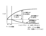
一方、高負荷領域でもアイドル時に必要な負荷トルク補償分を確保するためには、ドライバのアクセル操作によって操作可能なトルク分(車両用内燃機関では走行トルク分) がそれだけ制限され、外部負荷非投入時の最大出力が低下してしまう(図8参照) 。なお、操作可能なトルク分を前記負荷トルク補償分による制限を考慮せずぎりぎりまで大きく設定した場合は、外部負荷投入時にアクセルの中間開度で走行トルク分に負荷トルク補償分を加算したときの目標トルクに対応するスロットル弁開度が全開となってそれ以上トルクを増大することができず、良好なアクセル操作を行えない。
【0007】
本発明は、このような従来の課題に着目してなされたもので、トルクデマンド制御方式において、外部負荷駆動用の負荷トルク補償分を要求トルクに応じて適切に設定することにより、外部負荷投入時,非投入時共に良好なトルク制御を行えるようにした内燃機関の制御装置を提供することを目的とする。
【0008】
【課題を解決するための手段】
このため、請求項1に係る発明は、
機関の目標トルクを算出し、該目標トルクを得るように機関のトルクを制御する内燃機関の制御装置において、
外部負荷駆動用の負荷補償トルクを、運転者の操作量に応じた機関の要求トルクが大きいときは減少する補正演算を行って設定し、該設定された負荷補償トルクを前記要求トルクに加算して目標トルクを設定するようにしたことを特徴とする。
【0009】
請求項1に係る発明によると、
要求トルクが大きいときは、外部負荷投入によるトルク変化の影響が小さくなるので、外部負荷駆動用の負荷補償トルクを減少して設定してもエンストを防止でき、一方、該負荷補償トルクを減少した分、アクセル操作によるトルク操作分を増大することができ、車両用内燃機関では走行性能を向上できる。
【0010】
また、請求項2に係る発明は、図1に示すように、
機関の目標トルクを算出し、該目標トルクを得るように機関のトルクを制御する内燃機関の制御装置において、
外部負荷駆動用の負荷補償トルクを、運転者の操作量に応じた機関の要求トルクが大きいときは減少する補正演算を行って設定する負荷補償トルク設定手段と、
該設定された負荷補償トルクを前記要求トルクに加算して目標トルクを設定する目標トルク設定手段と、を含んで構成したことを特徴とする。
【0011】
請求項2に係る発明によると、
負荷補償トルク設定手段は、要求トルクが大きいときは外部負荷駆動用の負荷補償トルクを減少補正して設定し、目標トルク設定手段は該設定された負荷補償トルクに応じて目標トルクを設定し、該目標トルクとなるように機関のトルクが制御される。
【0012】
このようにすれば、要求トルクが大きいときは、外部負荷投入によるトルク変化の影響が小さくなるので、外部負荷駆動用の負荷補償トルクを減少して設定してもエンストを防止でき、一方、該負荷補償トルクを減少した分、アクセル操作によるトルク操作分を増大することができ、車両用内燃機関では走行性能を向上できる。
【0013】
また、請求項3に係る発明は、
所定以下の低負荷領域では一定の負荷補償トルクを設定し、前記低負荷領域以外の領域では前記低負荷領域用に設定された負荷補償トルクを、要求されるトルク量が大きいときほど大きく減少補正して設定することを特徴とする。
請求項3に係る発明によると、
外部負荷投入によるトルク変化の影響が大きい低負荷領域では、最大かつ一定の負荷補償トルクを与えてトルクショックを緩和しつつエンストを防止し、それより大きい負荷領域では、要求されるトルク量が大きいときほど外部負荷投入によるトルク変化の影響が小さくなるので、負荷補償トルクを大きく減少補正して設定することにより、アクセル操作によるトルク操作分を増大することができる。
【0014】
また、請求項4に係る発明は、
前記所定以下の低負荷領域は、アイドル領域であることを特徴とする。
請求項4に係る発明によると、
アイドル領域が外部負荷投入によるトルク変化の影響が大きいので、この領域で最大かつ一定の負荷補償トルクを与える。
【0015】
また、請求項5に係る発明は、
前記負荷補償トルクの減少補正量を、要求されるトルクに応じて設定されたテーブルから検索して求めることを特徴とする。
請求項5に係る発明によると、
テーブルに、要求されるトルクに応じて負荷補償トルクの減少補正量を極め細かく設定しておくことにより、要求トルクに応じて最適な負荷補償トルクを設定することができる。
【0016】
また、請求項6に係る発明は、
前記要求されるトルクのパラメータは、現在設定されている目標トルク値であることを特徴とする。
請求項6に係る発明によると、
要求されるトルクのパラメータを現在設定されている目標トルク値とすることにより、本発明の対象とするトルクデマンドを行う機関において、負荷補償トルクの補正を容易にロジックに組み込むことができる。
【0017】
また、エアコンやラジエータファン等複数の外部負荷を有する場合に、投入された全ての外部負荷に対する負荷補償トルクを含めた機関の全出力トルクに対する各負荷補償トルクの割合に正確に対応させて補正係数を設定することができる。
また、請求項7に係る発明は、
前記要求されるトルクのパラメータは、目標トルク値から負荷補償トルクを除いて設定される基本目標トルク値であることを特徴とする。
【0018】
請求項7に係る発明によると、
前記基本目標トルク値は、ドライバのアクセル操作によるトルク操作分であり、車両用内燃機関では走行分トルクに相当し、要求されるトルクのパラメータを該基本目標トルク値とすることにより、本発明の対象とするトルクデマンドを行う機関において、負荷補償トルクの補正を容易にロジックに組み込むことができる。
【0019】
また、請求項8に係る発明は、
前記要求されるトルクのパラメータは、アクセル開度であることを特徴とする。
請求項8に係る発明によると、
アクセル開度は、ドライバの意図を高速に精度良く検出できるトルクパラメータであり、要求されるトルクのパラメータを該アクセル開度とすることにより、高負荷時にドライバの操作可能なトルク範囲を十分に確保するのにドライバの意図を直接反映させることができる。
【0020】
また、請求項9に係る発明は、
均質燃焼又は成層燃焼のいずれか一方の燃焼方式を使用する内燃機関において、前記要求されるトルクのパラメータは、吸気圧力であることを特徴とする。
請求項9に係る発明によると、
要求されるトルクのパラメータを吸気圧力とすることにより、トルクデマンドを行わない機関の負荷補償トルク特性に非常に近い特性を実現することができ、また、環境変化にも対応できる。なお、均質燃焼と成層燃焼とを切り換える機関では、各燃焼方式に応じて吸気圧力が同一であってもトルクが変化するので、好ましくない。
【0021】
また、請求項10に係る発明は、
均質燃焼又は成層燃焼のいずれか一方の燃焼方式を使用する内燃機関において、前記要求されるトルクのパラメータは、吸入空気量であることを特徴とする。
請求項10に係る発明によると、
要求トルクのパラメータを吸入空気量とすることにより、通常の吸入空気量を検出して燃料噴射量制御を行う機関において、センサを追加することなく、精度の良いトルクパラメータを検出することができ、また、環境が変化(高地など) しても、正確なトルク情報を検出することができる。なお、均質燃焼と成層燃焼とを切り換える機関では、各燃焼方式に応じて吸入空気量が同一であってもトルクが変化するので、好ましくない。
【0022】
【発明の実施の形態】
以下に本発明の実施の形態を説明する。
図2は実施の一形態を示す直噴火花点火式内燃機関のシステム図である。
車両に搭載される内燃機関1の各気筒の燃焼室には、エアクリーナ2から吸気通路3により、電制スロットル弁4の制御を受けて、空気が吸入される。
【0023】
電制スロットル弁4は、コントロールユニット20からの信号により作動するステップモータ等により開度制御される。
そして、燃焼室内に燃料(ガソリン)を直接噴射するように、電磁式の燃料噴射弁(インジェクタ)5が設けられている。
燃料噴射弁5は、コントロールユニット20から機関回転に同期して吸気行程又は圧縮行程にて出力される噴射パルス信号によりソレノイドに通電されて開弁し、所定圧力に調圧された燃料を噴射するようになっている。そして、噴射された燃料は、吸気行程噴射の場合は燃焼室内に拡散して均質な混合気を形成し、また圧縮行程噴射の場合は点火栓6回りに集中的に層状の混合気を形成し、コントロールユニット20からの点火信号に基づき、点火栓6により点火されて、燃焼(均質燃焼又は成層燃焼)する。尚、燃焼方式は、空燃比制御との組合わせで、均質ストイキ燃焼、均質リーン燃焼(空燃比20〜30)、成層リーン燃焼(空燃比40程度)に分けられる。
【0024】
機関1からの排気は排気通路7より排出され、排気通路7には排気浄化用の触媒8が介装されている。
コントロールユニット20は、CPU、ROM、RAM、A/D変換器及び入出力インターフェイス等を含んで構成されるマイクロコンピュータを備え、各種のセンサから信号が入力されている。
【0025】
前記各種のセンサとしては、機関1のクランク軸又はカム軸回転を検出するクランク角センサ21,22が設けられている。これらのクランク角センサ21,22は、気筒数をnとすると、クランク角720°/n毎に、予め定めたクランク角位置(各気筒の圧縮上死点前の所定クランク角位置)で基準パルス信号REFを出力すると共に、1〜2°毎に単位パルス信号POSを出力するもので、基準パルス信号REFの周期などから機関回転数Neを算出可能である。
【0026】
この他、吸気通路3のスロットル弁4上流で吸入空気流量Qaを検出するエアフローメータ23、アクセル開度(アクセルペダルの踏込み量)ACCを検出するアクセルセンサ24、スロットル弁4の開度TVOを検出するスロットルセンサ25(スロットル弁4の全閉位置でONとなるアイドルスイッチを含む)、機関1の冷却水温Twを検出する水温センサ26、排気通路7にて排気空燃比のリッチ・リーンに応じた信号を出力するO2 センサ27、車速VSPを検出する車速センサ28などが設けられている。また、外部負荷としてのエアコンの駆動,非駆動に応じてON,OFFされるエアコンスイッチ29が設けられる。
【0027】
ここにおいて、コントロールユニット20は、前記各種のセンサからの信号を入力しつつ、内蔵のマイクロコンピュータにより、所定の演算処理を行って、電制スロットル弁4によるスロットル開度、燃料噴射弁5による燃料噴射量、燃料噴射時期及び点火栓6による点火時期を制御する。
次に、同上システムによるトルクデマンド制御の概要を、図3を参照して説明する。
【0028】
機関の目標トルクを算出し(101) 、該目標トルクに基づいて基準空燃比(例えば理論空燃比) における必要基本燃料量を算出する(102) 。一方、目標空燃比を算出し(103) 、該目標空燃比に応じて燃費効率による燃料量の補正を行い(104) 、該補正された燃料量に目標空燃比を乗じて目標吸入空気量を算出し(105) 、該目標吸入空気量に見合った目標スロットル開度を算出し(106) 、該目標スロットル開度が得られるように駆動制御を行って(107) 、電制スロットル弁を駆動する。
【0029】
本発明は前記目標トルク算出に際して使用される負荷補償トルクの算出に特徴がある。
以下、本発明に係る負荷補償トルクの算出を図に基づいて説明する。
図4は、第1の実施の形態に係る負荷補償トルクの算出ルーチンのフローチャートである。このルーチンは、一定周期例えば10ms毎に実行される。
【0030】
ステップ1では、エアコンスイッチACSWのON,OFFを判別する。
ステップ1でエアコンスイッチACSWがONと判定された時は、ステップ2へ進んでアイドル時にエアコンの駆動に要求される負荷補償トルクdTacを読み込む。
ステップ1でエアコンスイッチACSWがOFFと判定された時は、ステップ3へ進んで前記負荷補償トルクdTacを0にリセットする。これにより、エアコンのOFF時は、後述する最終的な負荷補償トルクdTac’も0となる。
【0031】
前記ステップ2又はステップ3からステップ4へ進み、該ステップ4では、アイドルスイッチのON,OFFによりアイドル状態であるか否かを判定する。
ステップ4でアイドル状態と判定された時は、ステップ5へ進んで前記負荷補償トルクdTacの補正係数Gadjを1にセットした後、ステップ8へ進む。該補正係数Gadjは後述するように負荷補償トルクdTacに乗じられる値であり、したがって、アイドル時は負荷補償トルクdTacの補正は行われない。
【0032】
ステップ4で非アイドル状態と判定された時は、ステップ6へ進んで要求トルクのパラメータを読み込む。該要求トルクのパラメータとしては、例えば後述するようにして求められる走行分目標トルクtTe0を読み込む。該走行分目標トルクTe0は、走行のみに必要なトルク分である。
【0033】
次いでステップ7へ進み、ステップ3で読み込んだ要求トルクのパラメータに基づいて、前記負荷補償トルクdTacの補正係数Gadjを算出する。例えば、要求トルクとして走行分目標トルクtTe0を読み込んだ場合には、該走行分目標トルクtTe0が増大するほど負荷補償トルクdTacを大きく減少補正させるため、次式(1) のような演算式によって、補正係数Gadjを算出する。
【0034】
Gadj=K/tTe0・・・(1) 但し、Kはゲイン
また、前記演算式による演算に代えて、図5に示すような走行分目標トルクtTe0に対する補正係数Gadjのテーブルを設定し、該テーブルから検索するようにしてもよく、極め細かく補正係数Gadjを求めることができる。
ステップ8では、次式(2) のように前記アイドル時相当の負荷補償トルクdTacに前記補正係数Gadjを乗算することにより、最終的な負荷補償トルクdTac’を算出する。
【0035】
dTac’=Gadj×dTac(2)
上記のようにして算出された負荷補償トルクdTac’を用いて、機関の目標トルクtTeを設定する。
該目標トルクtTeを設定するルーチンを、図6のフローチャートに従って説明する。このルーチンは、一定周期例えば10ms毎に実行される。
【0036】
ステップ11では、前記走行分目標トルクtTe0を算出する。具体的には、アクセル開度と機関回転速度(又は車速) とに基づいて、予め設定されたテーブルからの検索により求めればよい。
ステップ12では、次式のように前記走行分目標トルクtTe0に前記負荷補償トルクdTac’(エアコン非駆動時は0) を加算して、最終的な目標トルク目標トルクtTeを算出する。
【0037】
ステップ13では、前記目標トルクtTeをメモリにセットする。
以上のようにして設定された機関の目標トルクtTeを用いて、前記図3に示したようにトルク制御が実行される。
このようにすれば、アイドル時には、該アイドル時に必要な負荷補償トルクdTacを設定することにより、エアコン等外部負荷投入時のトルクショックを無くし、エンストを防止することができると共に、非アイドル時には要求トルクが増大するほど大きく減少して負荷補償トルクdTac’を設定することにより、図8に示すようにアクセル操作によるトルク操作分が増大し、走行性能が向上する。即ち、外部負荷投入時にアクセル全閉から全開まで連続的にトルクを増大できると共に、外部負荷非投入時の最大出力を十分大きく確保することができる。
【0038】
前記実施の形態では、非アイドルで負荷補償トルクを要求トルクの大きさに応じて減少補正するものを示したが、非アイドル時であってもアイドルに近い低負荷域では外部負荷投入によるトルクショックの影響を完全に無くすため、アイドル時と同一の負荷補償トルク値に固定しておく構成としてもよい。
図7は、上記構成を有する第2の実施の形態における負荷補償トルク設定ルーチンのフローチャートを示す。
【0039】
図4に示した第1の実施の形態と相違する部分は、ステップ4で非アイドル状態と判定されたときに、ステップ6で読み込んだ要求トルクのパラメータに応じてステップ21で負荷補償トルクの減少補正条件を満たしているかを判定する。
具体的には、要求トルクのパラメータ例えば走行分目標トルクtTe0が所定値tTe1以下の低負荷状態では、アイドル時と同様負荷補償トルクの減少補正条件を満たしていないと判断し、ステップ5へ進んで補正係数Gadjを1にセットし、所定値tTe1を超えるときのみ負荷補償トルクの減少補正条件を満たしていると判断してステップ7へ進み、負荷補償トルクの補正係数Gadjを算出する。該負荷補償トルクの補正係数Gadjを演算式によって算出する場合は、前記(1) 式を用いればよく、また、テーブルからの検索によって求めてもよいことは同様である。
【0040】
また、以上の実施の形態では、補正係数Gadjを求める際に使用する要求トルクのパラメータとして走行分目標トルクtTe0を使用し、この場合、本発明の対象とするトルクデマンドを行う機関において、負荷補償トルクの補正を容易にロジックに組み込むことができる。
また、要求トルクのパラメータとして現在設定されている目標トルクtTeを用いてもよい。この場合、外部負荷投入直後に投入前の負荷補償トルクを含まない目標トルクが用いられるが、瞬時であるので問題はなく、また、エアコンの他ラジエータファン等複数の外部負荷を有する場合に、投入された全ての外部負荷に対する負荷補償トルクを含めた機関の全出力トルクに対する各負荷補償トルクの割合に正確に対応させて補正係数を設定することができる。
【0041】
また、要求トルクのパラメータとしてアクセル開度を用いてもよく、ドライバの意図を高速に精度良く検出できるため、高負荷時にドライバの操作可能なトルク範囲を十分に確保するのにドライバの意図を直接反映させることができる。
また、以上示した走行分目標トルクtTe0、目標トルクtTe、アクセル開度等の要求トルクのパラメータは、前記実施の形態で示したように均質燃焼と成層燃焼とを切り換える内燃機関においては、該燃焼の切り換えに無関係に要求トルクの大きさを精度良く表すパラメータとして使用することができる。
【0042】
これに対し、均質燃焼又は成層燃焼のいずれか一方の燃焼方式を使用する内燃機関では、前記要求トルクのパラメータとして吸気負圧(ブースト圧) や吸入空気量を用いることもできる。なお、均質燃焼と成層燃焼とを切り換える機関では、各燃焼方式に応じて吸気負圧や吸入空気量が同一であってもトルクが変化するので、好ましくない。
【0043】
要求トルクのパラメータとして吸気負圧を用いる場合、吸気コレクタに圧力センサを設置して吸気負圧PB を検出し、該吸気負圧PB を要求トルクのパラメータとして読み込み、負荷補償トルクの補正係数Gadjを次式(3) のような演算式により算出する。又はテーブルからの検索等により求めることもできる。
Gadj=|PB |×K (Kは補正ゲイン) ・・・(3)
トルクデマンドを行わない機関では一般に負荷補償トルクはスロットル開度を一定増量することで与えており、この場合、負荷の増大に応じた吸気負圧の減少により負荷補償トルクが自動的に減少しており、したがって、前記のようにトルクデマンドを行う機関で負荷補償トルクを吸気負圧に応じて減少補正するものでは、前記トルクデマンドを行わない機関の負荷補償トルク特性に非常に近い特性を実現することができる。また、圧力センサの使用により環境変化にも対応できる。
【0044】
また、要求トルクのパラメータとして吸入空気量を用いる場合、通常の熱線式エアフロメータ等の吸入空気量センサを備えて吸入空気量を検出しつつ燃料噴射量制御を行う機関において、センサを追加することなく、精度の良いトルクパラメータを検出することができ、また、質量吸入空気量の検出により環境が変化(高地など) しても、正確なトルク情報を検出することができる。
【図面の簡単な説明】
【図1】 本発明の構成を示す機能ブロック図。
【図2】 本発明の一実施形態を示すシステム図。
【図3】 同上実施の形態におけるトルクデマンド制御の概要を示すブロック図。
【図4】 同上の実施形態において負荷補償トルクを設定するルーチンを示すフローチャート。
【図5】 同じく走行分目標トルク/負荷補償トルク補正係数変換テーブル。
【図6】 同じく目標トルクを設定するルーチンを示すフローチャート。
【図7】 第2の実施形態において負荷補償トルクを設定するルーチンを示すフローチャート。
【図8】 ドライバ操作トルクと負荷補償トルクとの比率を、従来例と本発明とで比較して示す図。
【符号の説明】
1 内燃機関
4 電制スロットル弁
5 燃料噴射弁
6 点火栓
20 コントロールユニット
29 エアコンスイッチ[0001]
BACKGROUND OF THE INVENTION
The present invention relates to a control device for an internal combustion engine that performs torque control by setting a target torque of the engine, and more particularly to torque control when driving an external load such as an air conditioner.
[0002]
[Prior art]
In recent years, in a vehicle internal combustion engine, development of a technique (torque demand control) for setting a target torque of the engine and performing torque control so as to obtain the target torque has been advanced. An engine that controls the amount of intake air, such as a gasoline engine, is equipped with an electronic throttle valve control device that electronically controls the opening of a throttle valve interposed in the intake system of the engine, and the throttle valve opening is controlled according to the target torque. Thus, a method of controlling the amount of air and the amount of fuel injection is common.
[0003]
On the other hand, when driving an external load such as an air conditioner, the torque required for the driving is provided as a load torque compensation component separately from the travel torque component, but this load torque compensation component is set as a torque correction value required during idling. ing.
[0004]
[Problems to be solved by the invention]
However, in the conventional torque demand control, the load torque compensation amount is set as a torque correction value necessary at the time of idling, and the torque control is performed by setting the target torque by uniformly incorporating the load torque compensation amount even at the time of idling. Therefore, there were the following problems.
[0005]
In other words, during idling, the effect of torque changes due to external loads such as air conditioners and radiator fans is large, and torque correction is very important from the standpoint of engine stall prevention. Therefore, the load torque compensation amount must be increased to perform sufficient torque correction. While it is necessary to set the torque correction, the influence of external load is small in the high load region and there is no concern about engine stall. Therefore, the importance of torque correction is not as high as that during idling.
[0006]
On the other hand, in order to secure the load torque compensation required during idling even in the high load range, the amount of torque that can be operated by the driver's accelerator operation (running torque for the vehicle internal combustion engine) is limited accordingly, and no external load is applied. The maximum output at the time is reduced (see FIG. 8). Note that when the operable torque is set to the maximum without considering the limitation due to the load torque compensation, the load torque compensation is added to the running torque at the accelerator middle opening when the external load is applied. The throttle valve opening corresponding to the target torque is fully opened, and the torque cannot be increased any further, and a favorable accelerator operation cannot be performed.
[0007]
The present invention has been made paying attention to such a conventional problem, and in the torque demand control system, by appropriately setting the load torque compensation amount for driving the external load according to the required torque, It is an object of the present invention to provide a control device for an internal combustion engine that can perform good torque control both when the engine is turned off and when it is not applied.
[0008]
[Means for Solving the Problems]
For this reason, the invention according to
In a control device for an internal combustion engine that calculates a target torque of an engine and controls the torque of the engine so as to obtain the target torque.
A load compensation torque for driving an external load is set by performing a correction calculation that decreases when the required torque of the engine according to the amount of operation of the driver is large, and the set load compensation torque is added to the required torque. The target torque is thus set .
[0009]
According to the invention of
When the required torque is large, the effect of torque change due to external load input is reduced, so even if the load compensation torque for driving the external load is reduced and set, the engine stall can be prevented, while the load compensation torque is reduced. Thus, the torque operation by the accelerator operation can be increased, and the traveling performance can be improved in the vehicle internal combustion engine.
[0010]
Moreover, as shown in FIG.
In a control device for an internal combustion engine that calculates a target torque of an engine and controls the torque of the engine so as to obtain the target torque.
Load compensation torque setting means for setting a load compensation torque for external load driving by performing a correction calculation that decreases when the required torque of the engine according to the operation amount of the driver is large ;
And a target torque setting means for setting the target torque by adding the set load compensation torque to the required torque .
[0011]
According to the invention of
The load compensation torque setting means reduces and sets the load compensation torque for external load driving when the required torque is large, and the target torque setting means sets the target torque according to the set load compensation torque, The engine torque is controlled to achieve the target torque.
[0012]
In this way, when the required torque is large, the influence of torque change due to the input of the external load is reduced. Therefore, even if the load compensation torque for driving the external load is reduced and set, the engine stall can be prevented. As the load compensation torque is reduced, the torque operation by the accelerator operation can be increased, and the vehicle internal combustion engine can improve the running performance.
[0013]
The invention according to
A constant load compensation torque is set in a low load region below a predetermined value, and in regions other than the low load region, the load compensation torque set for the low load region is greatly reduced as the required amount of torque increases. It is characterized by setting.
According to the invention of
In the low load region where the effect of torque change due to external load input is large, the engine torque is prevented while giving a maximum and constant load compensation torque to prevent engine stall. In the larger load region, the required amount of torque is large. Since the influence of the torque change due to the external load input becomes smaller as occasion demands, the amount of torque operation by the accelerator operation can be increased by setting the load compensation torque to be greatly decreased and corrected.
[0014]
The invention according to claim 4
The low load area below the predetermined range is an idle area.
According to the invention of claim 4,
Since the influence of the torque change due to the external load is great in the idle region, the maximum and constant load compensation torque is given in this region.
[0015]
The invention according to
The load compensation torque reduction correction amount is obtained by searching from a table set according to the required torque.
According to the invention of
By setting the amount of load compensation torque decrease correction in the table in accordance with the required torque, the optimum load compensation torque can be set according to the required torque.
[0016]
The invention according to claim 6
The required torque parameter is a currently set target torque value.
According to the invention of claim 6,
By setting the required torque parameter to the currently set target torque value, it is possible to easily incorporate the correction of the load compensation torque into the logic in the engine that performs the torque demand of the present invention.
[0017]
In addition, when there are multiple external loads such as air conditioners and radiator fans, the correction coefficient is made to accurately correspond to the ratio of each load compensation torque to the total output torque of the engine including the load compensation torque for all the external loads applied Can be set.
The invention according to
The required torque parameter is a basic target torque value set by excluding the load compensation torque from the target torque value.
[0018]
According to the invention of
The basic target torque value is the amount of torque operated by the driver's accelerator operation. In the internal combustion engine for a vehicle, the basic target torque value corresponds to the amount of traveling torque, and the required torque parameter is set as the basic target torque value. In the engine that performs the target torque demand, the correction of the load compensation torque can be easily incorporated into the logic.
[0019]
The invention according to
The required torque parameter is an accelerator opening.
According to the invention of
The accelerator opening is a torque parameter that can accurately detect the driver's intention at high speed. By making the required torque parameter the accelerator opening, a sufficient torque range that the driver can operate at high loads is secured. The driver's intention can be directly reflected.
[0020]
The invention according to claim 9 is
In an internal combustion engine that uses either one of homogeneous combustion and stratified combustion, the required torque parameter is intake pressure.
According to the invention of claim 9,
By setting the required torque parameter to the intake pressure, it is possible to realize a characteristic very close to the load compensation torque characteristic of an engine that does not perform torque demand, and to cope with environmental changes. An engine that switches between homogeneous combustion and stratified combustion is not preferable because the torque changes even if the intake pressure is the same according to each combustion method.
[0021]
The invention according to claim 10 is
In an internal combustion engine that uses either a homogeneous combustion or a stratified combustion method, the required torque parameter is an intake air amount.
According to the invention of claim 10,
By setting the required torque parameter as the intake air amount, it is possible to detect an accurate torque parameter without adding a sensor in an engine that detects the normal intake air amount and performs fuel injection amount control. In addition, accurate torque information can be detected even when the environment changes (such as high altitudes). An engine that switches between homogeneous combustion and stratified combustion is not preferable because the torque changes even if the intake air amount is the same according to each combustion method.
[0022]
DETAILED DESCRIPTION OF THE INVENTION
Embodiments of the present invention will be described below.
FIG. 2 is a system diagram of a direct injection spark ignition type internal combustion engine showing an embodiment.
Air is sucked into the combustion chamber of each cylinder of the
[0023]
The opening degree of the electronically controlled throttle valve 4 is controlled by a step motor or the like that is operated by a signal from the
An electromagnetic fuel injection valve (injector) 5 is provided to inject fuel (gasoline) directly into the combustion chamber.
The
[0024]
Exhaust gas from the
The
[0025]
As the various sensors, crank
[0026]
In addition, an
[0027]
Here, the
Next, an overview of torque demand control by the system will be described with reference to FIG.
[0028]
A target torque of the engine is calculated (101), and a necessary basic fuel amount at a reference air-fuel ratio (for example, theoretical air-fuel ratio) is calculated based on the target torque (102). On the other hand, the target air-fuel ratio is calculated (103), the fuel amount is corrected based on the fuel efficiency according to the target air-fuel ratio (104), and the target intake air amount is calculated by multiplying the corrected fuel amount by the target air-fuel ratio. Calculate (105), calculate the target throttle opening corresponding to the target intake air amount (106), perform drive control so as to obtain the target throttle opening (107), and drive the electric throttle valve To do.
[0029]
The present invention is characterized in the calculation of the load compensation torque used in calculating the target torque.
Hereinafter, calculation of the load compensation torque according to the present invention will be described with reference to the drawings.
FIG. 4 is a flowchart of a load compensation torque calculation routine according to the first embodiment. This routine is executed at regular intervals, for example, every 10 ms.
[0030]
In
When it is determined in
When it is determined at
[0031]
The process proceeds from
When it is determined in step 4 that the engine is in the idle state, the process proceeds to step 5 to set the correction coefficient Gadj of the load compensation torque dTac to 1, and then proceeds to step 8. The correction coefficient Gadj is a value that is multiplied by the load compensation torque dTac, as will be described later. Therefore, the correction of the load compensation torque dTac is not performed during idling.
[0032]
When it is determined in step 4 that the vehicle is in the non-idle state, the process proceeds to step 6 and the parameter of the required torque is read. As the parameter of the required torque, for example, a travel target torque tTe0 obtained as described later is read. The travel target torque Te0 is a torque required only for travel .
[0033]
Next, the routine proceeds to step 7, where the correction coefficient Gadj of the load compensation torque dTac is calculated based on the required torque parameter read in
[0034]
Gadj = K / tTe0 (1) where K is a gain, or a table of correction coefficient Gadj for travel target torque tTe0 as shown in FIG. The correction coefficient Gadj can be obtained very finely.
In
[0035]
dTac ′ = Gadj × dTac (2)
The engine target torque tTe is set using the load compensation torque dTac ′ calculated as described above.
A routine for setting the target torque tTe will be described with reference to the flowchart of FIG. This routine is executed at regular intervals, for example, every 10 ms.
[0036]
In
In
[0037]
In step 13, the target torque tTe is set in the memory.
Using the engine target torque tTe set as described above, torque control is executed as shown in FIG.
In this way, by setting the load compensation torque dTac necessary at the time of idling at the time of idling, it is possible to eliminate torque shock when an external load such as an air conditioner is turned on and to prevent engine stall, and at the time of non-idling, the required torque By setting the load compensation torque dTac ′ so as to increase, the amount of torque operation by the accelerator operation increases as shown in FIG. 8, and the running performance improves. That is, when the external load is applied, the torque can be continuously increased from the accelerator fully closed to the fully open, and the maximum output when the external load is not applied can be secured sufficiently large.
[0038]
In the above-described embodiment, the non-idle load compensation torque is corrected so as to be reduced according to the magnitude of the required torque. In order to completely eliminate the influence of the above, the load compensation torque value may be fixed to the same value as that during idling.
FIG. 7 shows a flowchart of a load compensation torque setting routine in the second embodiment having the above-described configuration.
[0039]
The difference from the first embodiment shown in FIG. 4 is that when the non-idle state is determined in step 4, the load compensation torque is reduced in
Specifically, in a low load state in which the required torque parameter, for example, the travel target torque tTe0 is equal to or less than the predetermined value tTe1, it is determined that the load compensation torque decrease correction condition is not satisfied as in the idling state, and the process proceeds to step 5 The correction coefficient Gadj is set to 1, and only when the predetermined value tTe1 is exceeded, it is determined that the load compensation torque decrease correction condition is satisfied, and the process proceeds to step 7 to calculate the load compensation torque correction coefficient Gadj. When calculating the correction coefficient Gadj of the load compensation torque by an arithmetic expression, the above expression (1) may be used, and it may be obtained by searching from a table.
[0040]
In the above embodiment, the travel target torque tTe0 is used as a parameter of the required torque used when the correction coefficient Gadj is obtained. In this case, in the engine that performs the torque demand targeted by the present invention, the load compensation is performed. Torque correction can be easily incorporated into the logic.
Alternatively, the currently set target torque tTe may be used as a required torque parameter. In this case, the target torque that does not include the load compensation torque before the input immediately after the external load is applied is used, but there is no problem because it is instantaneous, and it is applied when there are multiple external loads such as an air conditioner radiator fan. The correction coefficient can be set in correspondence with the ratio of each load compensation torque to the total output torque of the engine including the load compensation torque for all external loads.
[0041]
In addition, the accelerator opening may be used as a parameter for the required torque, and the driver's intention can be detected accurately at high speed. It can be reflected.
Further, the required torque parameters such as the travel target torque tTe0, the target torque tTe, and the accelerator opening shown above are the same in the internal combustion engine that switches between homogeneous combustion and stratified combustion as shown in the embodiment. It can be used as a parameter that accurately represents the magnitude of the required torque regardless of the switching.
[0042]
On the other hand, in an internal combustion engine that uses either one of homogeneous combustion and stratified combustion, intake negative pressure (boost pressure) or intake air amount can be used as a parameter for the required torque. An engine that switches between homogeneous combustion and stratified combustion is not preferable because the torque changes even if the intake negative pressure and the intake air amount are the same according to each combustion method.
[0043]
When intake negative pressure is used as a required torque parameter, a pressure sensor is installed in the intake collector to detect intake negative pressure PB, read the intake negative pressure PB as a required torque parameter, and a load compensation torque correction coefficient Gadj is calculated. It is calculated by an arithmetic expression such as the following expression (3). Alternatively, it can be obtained by searching from a table or the like.
Gadj = | PB | × K (K is a correction gain) (3)
In an engine that does not perform torque demand, load compensation torque is generally given by increasing the throttle opening by a certain amount. In this case, the load compensation torque is automatically reduced by a decrease in intake negative pressure as the load increases. Therefore, in the engine that performs torque demand as described above, when the load compensation torque is corrected to decrease according to the intake negative pressure, a characteristic very close to the load compensation torque characteristic of the engine that does not perform the torque demand is realized. be able to. In addition, the use of a pressure sensor can cope with environmental changes.
[0044]
In addition, when the intake air amount is used as a parameter for the required torque, a sensor is added in an engine that includes an intake air amount sensor such as a normal hot-wire air flow meter and controls the fuel injection amount while detecting the intake air amount. Therefore, accurate torque parameters can be detected, and accurate torque information can be detected even if the environment changes (e.g., high altitude) by detecting the mass intake air amount.
[Brief description of the drawings]
FIG. 1 is a functional block diagram showing a configuration of the present invention.
FIG. 2 is a system diagram showing an embodiment of the present invention.
FIG. 3 is a block diagram showing an outline of torque demand control in the embodiment.
FIG. 4 is a flowchart showing a routine for setting a load compensation torque in the embodiment.
FIG. 5 is a travel target torque / load compensation torque correction coefficient conversion table.
FIG. 6 is a flowchart showing a routine for similarly setting a target torque.
FIG. 7 is a flowchart showing a routine for setting a load compensation torque in the second embodiment.
FIG. 8 is a diagram showing a ratio of a driver operation torque and a load compensation torque in comparison with a conventional example and the present invention.
[Explanation of symbols]
1 Internal combustion engine 4
20 Control unit
29 Air conditioner switch
Claims (9)
外部負荷駆動用の負荷補償トルクを、運転者の操作量に応じた機関の要求トルクが大きいときは減少する補正演算を行って設定し、該設定された負荷補償トルクを前記要求トルクに加算して目標トルクを設定するようにしたことを特徴とする内燃機関の制御装置。In a control device for an internal combustion engine that calculates a target torque of an engine and controls the torque of the engine so as to obtain the target torque.
A load compensation torque for driving an external load is set by performing a correction calculation that decreases when the required torque of the engine according to the amount of operation of the driver is large, and the set load compensation torque is added to the required torque. A control device for an internal combustion engine, characterized in that a target torque is set.
外部負荷駆動用の負荷補償トルクを、運転者の操作量に応じた機関の要求トルクが大きいときは減少する補正演算を行って設定する負荷補償トルク設定手段と、
該設定された負荷補償トルクを前記要求トルクに加算して目標トルクを設定する目標トルク設定手段と、を含んで構成したことを特徴とする内燃機関の制御装置。In a control device for an internal combustion engine that calculates a target torque of an engine and controls the torque of the engine so as to obtain the target torque.
Load compensation torque setting means for setting a load compensation torque for external load driving by performing a correction calculation that decreases when the required torque of the engine according to the operation amount of the driver is large;
A control device for an internal combustion engine, comprising: target torque setting means for setting a target torque by adding the set load compensation torque to the required torque.
Priority Applications (1)
| Application Number | Priority Date | Filing Date | Title |
|---|---|---|---|
| JP35085197A JP3812111B2 (en) | 1997-12-19 | 1997-12-19 | Control device for internal combustion engine |
Applications Claiming Priority (1)
| Application Number | Priority Date | Filing Date | Title |
|---|---|---|---|
| JP35085197A JP3812111B2 (en) | 1997-12-19 | 1997-12-19 | Control device for internal combustion engine |
Publications (2)
| Publication Number | Publication Date |
|---|---|
| JPH11182284A JPH11182284A (en) | 1999-07-06 |
| JP3812111B2 true JP3812111B2 (en) | 2006-08-23 |
Family
ID=18413324
Family Applications (1)
| Application Number | Title | Priority Date | Filing Date |
|---|---|---|---|
| JP35085197A Expired - Fee Related JP3812111B2 (en) | 1997-12-19 | 1997-12-19 | Control device for internal combustion engine |
Country Status (1)
| Country | Link |
|---|---|
| JP (1) | JP3812111B2 (en) |
Families Citing this family (1)
| Publication number | Priority date | Publication date | Assignee | Title |
|---|---|---|---|---|
| JP2013151892A (en) * | 2012-01-25 | 2013-08-08 | Nissan Motor Co Ltd | Internal combustion engine control device |
-
1997
- 1997-12-19 JP JP35085197A patent/JP3812111B2/en not_active Expired - Fee Related
Also Published As
| Publication number | Publication date |
|---|---|
| JPH11182284A (en) | 1999-07-06 |
Similar Documents
| Publication | Publication Date | Title |
|---|---|---|
| JP3514077B2 (en) | Engine throttle control | |
| JP3768296B2 (en) | In-cylinder injection type spark ignition internal combustion engine control device | |
| JP3683681B2 (en) | Control device for direct-injection spark-ignition internal combustion engine | |
| US6779508B2 (en) | Control system of internal combustion engine | |
| US7121233B2 (en) | Control apparatus for an internal combustion engine | |
| EP1270910B1 (en) | Control apparatus for internal combustion engine | |
| JP3175601B2 (en) | Air intake control system for lean burn engine | |
| JP4415509B2 (en) | Control device for internal combustion engine | |
| JPH1089122A (en) | Control device for idling speed of laminated combustion engine | |
| JP3564520B2 (en) | Engine idle speed control device | |
| JP3812138B2 (en) | Control device for turbocharged engine | |
| JP3812111B2 (en) | Control device for internal combustion engine | |
| JP2560695B2 (en) | Deceleration control device for internal combustion engine | |
| JP4339599B2 (en) | In-cylinder injection internal combustion engine control device | |
| JP2000145524A (en) | Internal combustion engine having variable turbo charger | |
| JP3872617B2 (en) | Intake air amount control device for supercharged engine | |
| JP3362616B2 (en) | Fuel injection control device for stratified combustion internal combustion engine | |
| JP3307306B2 (en) | Combustion system control device for internal combustion engine | |
| JPH1162658A (en) | Control device for internal combustion engine | |
| JP2002317681A (en) | Control device of internal combustion engine | |
| JP2001248487A (en) | Control device for internal combustion engine | |
| JPH09287494A (en) | Controller for internal combustion engine having electronically controlled throttle | |
| JP3916416B2 (en) | Control device for internal combustion engine | |
| JPH11107815A (en) | Combustion controller for lean combustion internal combustion engine | |
| JP2752463B2 (en) | Intake control device for internal combustion engine |
Legal Events
| Date | Code | Title | Description |
|---|---|---|---|
| A131 | Notification of reasons for refusal |
Free format text: JAPANESE INTERMEDIATE CODE: A131 Effective date: 20050531 |
|
| A521 | Written amendment |
Free format text: JAPANESE INTERMEDIATE CODE: A523 Effective date: 20050729 |
|
| TRDD | Decision of grant or rejection written | ||
| A01 | Written decision to grant a patent or to grant a registration (utility model) |
Free format text: JAPANESE INTERMEDIATE CODE: A01 Effective date: 20060509 |
|
| A61 | First payment of annual fees (during grant procedure) |
Free format text: JAPANESE INTERMEDIATE CODE: A61 Effective date: 20060522 |
|
| R150 | Certificate of patent or registration of utility model |
Free format text: JAPANESE INTERMEDIATE CODE: R150 |
|
| LAPS | Cancellation because of no payment of annual fees |