JP3804527B2 - Microscope system - Google Patents
Microscope system Download PDFInfo
- Publication number
- JP3804527B2 JP3804527B2 JP2001383609A JP2001383609A JP3804527B2 JP 3804527 B2 JP3804527 B2 JP 3804527B2 JP 2001383609 A JP2001383609 A JP 2001383609A JP 2001383609 A JP2001383609 A JP 2001383609A JP 3804527 B2 JP3804527 B2 JP 3804527B2
- Authority
- JP
- Japan
- Prior art keywords
- image
- display
- adjusted
- imaging
- microscope
- Prior art date
- Legal status (The legal status is an assumption and is not a legal conclusion. Google has not performed a legal analysis and makes no representation as to the accuracy of the status listed.)
- Expired - Fee Related
Links
Images


Description
【0001】
【発明の属する技術分野】
本発明は、試料の画像を表示する機能を備えた顕微鏡システムに関する。
【0002】
【従来の技術】
従来より、試料を載置するステージ、対物レンズおよび絞りなどの被調整部材が電動化された顕微鏡と、顕微鏡による観察像を撮像する電子カメラなどの撮像装置と、このような撮像により得られる試料の画像を表示するモニタなどの表示装置とを備えた顕微鏡システムが知られている。
【0003】
このような顕微鏡システムにおいて、顕微鏡の制御は、それぞれの被調整部材に対するユーザの指示に応じて行われていた。例えば、倍率を変更する場合、ユーザは、まずレボルバを切り換え、好みの倍率が得られない場合は中間変倍機構を調整する。
従来の電動化された顕微鏡システムには、倍率変更に伴う明るさやコントラストの変化に対応すべく顕微鏡の各被調整部材(開口絞り、NDフィルタ、ランプなど)を予め記憶されている状態(設計値)へと制御する機能を備えたものがある。しかし、このような顕微鏡システムにおいて、顕微鏡では、ユーザが顕微鏡の接眼レンズを介して試料を観察することを目的として、接眼部で最適化された光量となるように被調整部材の制御が行われ、撮像装置では、その制御された光量の試料の像を撮像するための制御が行われていた。すなわち、顕微鏡に対する制御と撮像装置に対する制御とが独立して行われていた。
【0004】
【発明が解決しようとする課題】
このような顕微鏡システムでは、顕微鏡の接眼部での試料像が最適な明るさに制御されていても、撮像装置側では自動露出制御範囲外となり、表示装置を介して試料を観察する場合、表示装置に表示される試料の画像が明るすぎたり、暗すぎたりする場合があり、ユーザはこのような場合、再度、顕微鏡と撮像装置とのそれぞれに対して微調整を行わなければならなかった。同様に、試料像のコントラストが低下した場合も両者の微調整が必要であった。
【0005】
また、従来の顕微鏡システムでは、発光量が限定される蛍光観察(主に落射蛍光観察)を効率良く行うために、DIC(微分干渉コントラスト)観察で試料の構図や大きさを決定してから蛍光観察を行う場合がある。このような場合、まず、DIC観察を行うための被調整部材が顕微鏡装置内で設定され、その後、蛍光観察を行うための被調整部材が顕微鏡装置内で設定されるが、DIC観察から蛍光観察への切り換えにより、表示画面に表示される画像の明るさやコントラストが急激に変化してしまうことがある。そのため、ユーザが、画像を最適な状態にするように明るさの調整を行ったり、コントラストの調整を行っている間に発光量が減少してしまい、観察を効率良く行うことができなかった。
【0006】
本発明は、以上説明したような問題に鑑みてなされたものであり、ユーザが煩雑な作業を行うことなく、表示装置に表示される試料の画像を最適な状態に制御すること(以下、「画像の最適化」と称する)ができる顕微鏡システムを提供することを目的とする。
【0007】
【課題を解決するための手段】
請求項1に記載の顕微鏡システムは、試料の観察状態を変更する複数の被調整部材および前記複数の被調整部材を電動制御する顕微鏡制御部を備えた顕微鏡と、前記試料の光学像を撮像して画像を生成する撮像手段と、前記撮像手段により生成される画像を表示し、前記表示画像に基づき表示条件を変更できる表示手段と、前記表示手段により表示すべき画像の前記表示条件に応じて、前記複数の被調整部材のうち制御すべき被調整部材の制御内容と前記撮像手段の撮像条件とを関連付けて決定し、決定した内容に従って前記被調整部材と前記撮像手段とを互いに関連させて制御し、前記撮像手段からの画像を画像処理して前記表示手段に表示する制御手段とを備えたことを特徴とする。
【0008】
請求項2に記載の顕微鏡システムは、請求項1に記載の顕微鏡システムにおいて、前記表示手段の表示画面上において前記画像の表示条件を設定できる表示条件設定手段を備え、前記制御手段は、前記撮像手段により生成される画像を前記表示手段に表示させる画像処理手段と、前記複数の被調整部材の制御内容を示す信号を前記画像処理手段に伝達するインタフェース部とを備えたことを特徴とする。
【0009】
請求項3に記載の顕微鏡システムは、請求項2に記載の顕微鏡システムにおいて、前記制御手段は、前記試料の観察倍率を変更すると、まず前記表示条件設定手段により設定された画像の明るさ条件に応じて前記撮像手段が適正露出となるように、前記複数の被調整部材のうち制御すべき被調整部材を制御し、次に前記撮像手段の撮像条件を決定することを特徴とする。
【0010】
請求項4に記載の顕微鏡システムは、請求項2または請求項3の何れか1項に記載の顕微鏡システムにおいて、前記制御手段は、前記表示条件設定手段により明るさ以外の画像の表示条件が設定された場合、前記表示手段に既に表示されている画像の明るさが保たれるように、前記制御すべき被調整部材の制御内容と前記撮像条件とを決定することを特徴とする。
【0011】
請求項5に記載の顕微鏡システムは、請求項1に記載の顕微鏡システムにおいて、検鏡方法の設定に係るユーザ操作を受け付ける検鏡方法設定手段を備え、前記制御手段は、前記表示手段に既に表示されている画像の表示条件が保たれるように、前記制御すべき被調整部材の制御内容と前記撮像条件とを、前記検鏡方法設定手段により設定された検鏡方法に基づいて決定することを特徴とする。
請求項6に記載の顕微鏡システムは、請求項5に記載の顕微鏡システムにおいて、前記制御手段は、前記表示手段に表示されている画像の明るさが最適に保たれるように、前記制御すべき被調整部材の制御内容と前記撮像条件とを、前記検鏡方法設定手段により設定された検鏡方法に基づいて決定することを特徴とする。
【0012】
【発明の実施の形態】
以下、本発明の実施形態について図面を用いて詳細に説明する。
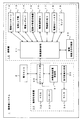
図1は、本発明の実施形態における顕微鏡システムの構成を示すブロック図である。
図1に示すように、顕微鏡システム1は、電子カメラ2、顕微鏡10および画像処理装置30から構成され、光学的に像を観察する接眼部を備えていない。
【0013】
顕微鏡10は顕微鏡制御部11を備え、顕微鏡制御部11には各被調整部材が相互に接続されている。このような被調整部材として図1では、電動XYステージ12、電動Z上下動13、電動レボルバ14、電動中間変倍機構15、電動視野絞り16、電動開口絞り17、電動NDフィルタ18およびランプ19を示している。
【0014】
また、顕微鏡10は、検鏡方法に応じて使用される被調整部材(図示省略)から成る電動検鏡方法切換部20を備え、電動検鏡方法切換部20と顕微鏡制御部11とは相互に接続されている。
画像処理装置30は、画像処理装置制御部31、マウス32、キーボード33、モニタ34、インタフェース部35および表示画像生成部36を備えている。画像処理装置制御部31は、インタフェース部35を介して、マウス32およびキーボード33に接続され、マウス32およびキーボード33の状態を示す信号をインタフェース部35を介して取得する。
【0015】
また、画像処理装置制御部31は、表示画像生成部36に接続される。表示画像生成部36は、液晶表示装置などのモニタ34に接続され、画像処理装置制御部31の指示に応じて、モニタ34に表示すべき画像を生成して、モニタ34に表示する。
さらに、画像処理装置制御部31は、インタフェース部35を介して、電子カメラ2と相互に接続され、電子カメラ2に対して撮像条件などを通知し、電子カメラ2により得られる試料の画像データを取得し、表示画像生成部36に出力すると共に、不図示の記録部(ハードディスク、コンパクトフラッシュ(登録商標)など)に記録する。
【0016】
液晶表示装置などのモニタ34の表示条件と画像処理装置制御部31での制御条件(撮像条件を含む)とはマッチングがとれており、ユーザが見ているモニタ34で表示された画像と、記録部に記録された画像データとは一致している。
また、画像処理装置制御部31は、インタフェース部35を介して、顕微鏡10内の顕微鏡制御部11と相互に接続され、顕微鏡制御部11に対して各被調整部材の制御内容を通知し、顕微鏡制御部11から供給される各被調整部材の状態を示すデータを取得する。
【0017】
以上説明したような構成の顕微鏡システム1において、ユーザ操作は、モニタ34に表示されるGUI(Graphical User Interface)の表示画面に基づくマウス32やキーボード33の操作によって実現される。
GUIの表示画面は、画像処理装置制御部31の指示に応じて表示画像生成部36で生成される。表示画像生成部36では、電子カメラ2により得られる試料の画像データに所定のアイコンを重ね合わせて、GUIの表示画面を生成する。
【0018】
図2は、モニタ34に表示されるGUIの表示画面の例を示す図である。
図2において、モニタ34の画像表示領域40には、試料の画像が表示されており、画像表示領域40上に各種アイコンが配置されている。
画像表示領域40の右側の領域に配置されているアイコン41〜47は、画像の表示条件の設定に係るユーザ操作を受け付けるためのアイコンである。本実施形態では、表示条件として、大きさ、コントラスト、明るさを用い、アイコン41および42の操作により大きさの設定が行われ、アイコン43およびアイコン44の操作によりコントラストの設定が行われ、アイコン45およびアイコン46の操作により明るさの設定が行われる。マクロ観察用アイコン47は、試料全体の画像を表示させる際に操作される。
【0019】
また、画像表示領域40の下側の領域に配置されているアイコン60〜64は、検鏡方法の設定に係るユーザ操作を受け付けるためのアイコンである。アイコン60の操作により明視野観察の設定が行われ、アイコン61の操作により暗視野観察の設定が行われ、アイコン62の操作により蛍光観察の設定が行われ、アイコン63の操作により位相差観察の設定が行われ、アイコン64の操作によりDIC観察の設定が行われる。
【0020】
以上説明したアイコンの操作のほかに、GUIの表示画面では、マウス32などを介して、画像表示領域40上の任意の領域(図2では、点線で囲まれる領域に相当する)を拡大表示させるための領域指定の操作や、画像表示領域40上の任意の位置を視野の中心に移動させるさせるための視野中心指定の操作が行われる。
【0021】
図3は、本発明の実施形態における顕微鏡システム1の動作を示すフローチャートであり、特に、図2に示したGUIの表示画面に対する操作が行われた際の画像処理装置制御部31の動作を示している。このような動作は、画像処理装置制御部31内の不図示のメモリに予め記録されている制御プログラムに応じて行われるものとする。
【0022】
以下、図3を用いて画像処理装置制御部31の動作を説明する。
まず、ステップS1において、画像処理装置制御部31は、マウス32やキーボード33を介し、ユーザによるGUIの表示画面に対する操作が行われた否かを判定する。そして、このような操作が行われなかった場合、画像処理装置制御部31は、ステップS1を繰り返し、操作が行われるまで待機する。
【0023】
ステップS2において、画像処理装置制御部31は、GUIの表示画面に対する操作に応じて、予め内部に記録されているルックアップテーブル(以下、「LUT」と称する)と、既に表示画面に表示されている画像の表示条件とに基づき、顕微鏡10の制御内容(制御すべき被調整部材および制御すべき被調整部材の制御量など)と、電子カメラ2の撮像条件とを関連付けて決定する。
【0024】
なお、既に表示画面に表示されている画像の表示条件としては、大きさ、コントラスト、明るさなどがあり、このような表示条件は、モニタ34上の座標位置データ、輝度情報、高周波成分情報などに基づくものとする。
図4は、ユーザにより表示条件の設定に係る操作が行われた場合に用いられるLUTの例である。
【0025】
画像処理装置制御部31は、ユーザにより表示条件の設定に係る操作(アイコン41〜47に対する操作など)が行われると、操作内容に応じて、図4に示すLUTと、既に表示画面に表示されている画像の表示条件とに基づき、○印の記されている顕微鏡10の制御内容と電子カメラ2の撮像条件とを関連付けて決定する。このような決定の際、既に表示画面に表示されている画像の表示条件が変動する可能性がある場合、さらに、△印の記されている顕微鏡10の制御内容と電子カメラ2の撮像条件とを関連付けて決定する。
【0026】
図5は、ユーザにより検鏡方法の設定に係る操作が行われた場合に用いられるLUTの例である。
画像処理装置制御部31は、ユーザにより検鏡方法の設定に係る操作(アイコン60〜64に対する操作など)が行われると、検鏡方法に応じて、図5に示すLUTと、既に表示画面に表示されている画像の表示条件とに基づき、○印の記されている顕微鏡10の制御内容を決定する。このような決定の際、既に表示画面に表示されている画像の表示条件が変動する可能性がある場合、さらに、△印の記されている顕微鏡10の制御内容を決定する。
【0027】
なお、図5には、電動検鏡方法切換部20の被調整部材として、電動フィルタブロック、電動エピシャッタ、電動アナライザ、電動ポラライザおよび電動ユニバーサルコンデンサが示されているが、このような構成は公知技術であるので詳細な説明および図示を省略する。また、電子カメラ2の撮像条件については、既に表示画面に表示されている画像の表示条件を保つように決定されるものとする。
【0028】
ステップS3において、画像処理装置制御部31は、ステップS2において決定した内容に従って顕微鏡10および電子カメラ2に対する制御を行う。すなわち、画像処理装置制御部31は、ステップS2において決定した顕微鏡10の制御内容を顕微鏡制御部11に通知して制御するとともに、電子カメラ2の撮像条件を電子カメラ2に通知して制御する。
【0029】
したがって、本実施形態の顕微鏡システム1によれば、ユーザが、例えば、大きさ設定用のアイコン41および42を操作すると、図4のLUTにおいて、○印が記されている顕微鏡10の被調整部材の制御内容(電動レボルバ14、電動中間変倍機構15)および電子カメラ2の電子ズームの撮像条件が関連付けて決定され、制御される。
【0030】
上記のように大きさ設定用アイコン41,42の操作により、試料の観察倍率が変更されると、大きさ以外の撮像条件が変動する可能性がある。その場合には、従来の電動化された顕微鏡システムのように接眼部に合わせて各種被調整部材(NDフィルタ、各種絞りなど)を調整した後に電子カメラの撮像条件を決定するのでは既に述べたように自動制御範囲外となる問題があるので、顕微鏡10の被調整部材と電子カメラ2の撮像条件とを図4に示すように適宜、調整することになる。
【0031】
例えば、△印が記されている顕微鏡10の電動Z上下動13、電動視野絞り16、電動開口絞り17、電動NDフィルタ18、ランプ19および電子カメラ2のCCD露光時間、ゲインコントロールも関連付けて制御される。
つまり、本実施形態の顕微鏡システム1によれば、ユーザが、大きさ設定用のアイコン41,42を操作するだけで、大きさを変更するとともに、大きさの変更後に大きさ以外の表示条件(例えば、明るさ)が保たれるように顕微鏡10の制御内容と電子カメラ2の撮像条件とが決定されることになる。
【0032】
具体的には、表示条件の明るさ(露出条件)を決定する場合に、まず顕微鏡10の電動開口絞り17や電動NDフィルタ18により露出がアンダー気味になるように設定しておき、電子カメラ2のCCD露出時間(電子シャッタ)やゲインコントロールによって適正露出となるように上記の撮像条件を決定する。このように決定すれば、電子カメラ2側での露出制御範囲が広がり、撮像される試料側の明るさ(露出)変化に対して十分に対応でき、適正露出を得ることができる。
また、それでも電子カメラ2側において適正露出制御範囲外となっている場合には、顕微鏡10の各種被調整部材が再調整され、電子カメラ2側で適正露出を得ることができる。すなわち、顕微鏡10の各種被調整部材の制御内容と電子カメラ2の撮像条件とを互いに関連させ、補い合うように制御する。
【0033】
そのため、ユーザは、顕微鏡10の被調整部材のそれぞれに対して制御を行う必要や、電子カメラ2の撮像条件を一つずつ設定する必要が無くなり、表示画面に表示されている画像をどのようにしたいかというイメージに基づいて指示を行うことが可能になる。その結果、ユーザは顕微鏡10および電子カメラ2のどの部分を制御すべきかを意識する必要も無くなり、一般的な顕微鏡および電子カメラについての知識や経験が乏しい初心者などのユーザでも手軽に利用することが可能になる。
【0034】
同様に、図2に示されるコントラスト設定用アイコン43,44を操作すると、図4に示される顕微鏡10の被調整部材の制御内容(電動開口絞り17、電動NDフィルタ18、ランプ19)と電子カメラ2の撮像条件(CCD露光時間、ゲインコントロール、カラーバランス、輪郭強調)とが関連付けて制御される。具体的には、図4に示されるように、まず○印の付いている顕微鏡10の電動開口絞り17と電子カメラ2の輪郭強調の撮像条件とが決定され、所定のコントラストが得られれば終了するが、更に微調整が必要な場合には△印の付いている顕微鏡10の被調整部材と電子カメラ2の撮像条件とが補い合う制御がなされ、適宜、調整されることになる。
【0035】
その他、図4に示されている明るさ設定用アイコン(図2の45,46)、マクロ画像用アイコン(図2の47)、領域指定操作や視野中心指定操作をすると、上述したのと同様に、○印の付いているものから優先的に制御され、補助的に△印の付いたものが制御されることになる。
また、ユーザが、例えば、位相差観察設定用のアイコン63を操作すると、図5のLUTにおいて、○印が記されている顕微鏡10の電動視野絞り16、電動開口絞り17、電動NDフィルタ18、電動フィルタブロック、電動エピシャッタ、電動アナライザ、電動ポラライザおよび電動ユニバーサルコンデンサが関連付けて制御され、検鏡方法の変更に伴って明るさなどの表示条件が変動する可能性がある場合、△印が記されているランプ19も制御されるとともに、電子カメラ2の撮像条件も関連付けて決定され、制御される。
【0036】
つまり、本実施形態の顕微鏡システム1によれば、ユーザが、検鏡方法の設定に係るアイコン(図2の60〜64)を操作するだけで、検鏡方法を切り換えるとともに、検鏡方法の変更後に画像の表示条件が保たれるように、顕微鏡10の制御すべき被調整部材と電子カメラ2の撮像条件とを関連付けて決定する。
【0037】
例えば、蛍光観察の場合に蛍光の退色を防ぐために、DIC観察において焦点合わせや検査領域を決定し、その後に蛍光観察で検査するので、DIC観察から蛍光観察への検鏡法切換えは、生物顕微鏡などでは良く行われる。この場合、DIC観察を設定すると(図2の64)、図5に示される顕微鏡10の通常被調整部材の制御内容(電動視野絞り16を開放絞りに設定、電動開口絞り17を開放絞りに設定、電動NDフィルタ18を減光率の最低なものに設定して光量最大に設定、ランプ19は任意調整)と検鏡方法切換え用の被調整部材(電動フィルタブロックを中間位置に設定、電動エピシャッタを閉に設定、電動アナライザを光路中に設定、電動ポラライザを光路中に設定、電動ユニバーサルコンデンサをDIC位置に設定)とが関連付けて制御される。その後に、蛍光観察に設定されると、図5に示されるように顕微鏡10の通常被調整部材の制御内容(電動視野絞り16、電動開口絞り17及び電動NDフィルタ18は透過照明用であるので制御されず、ランプ19は消灯される)と検鏡方法切換え用の被調整部材(電動フィルタブロックを任意フィルタに設定、電動エピシャッタを閉或いは開に設定、電動アナライザを光路中に設定、電動ポラライザを光路中に設定、電動ユニバーサルコンデンサを中間位置に設定)とが関連付けて制御される。
【0038】
このように、DIC観察から蛍光観察に検鏡方法を切り換えると、電子カメラ2の撮像条件は、DIC観察では顕微鏡10のランプ19と関連付けられ画像の表示条件が制御され、蛍光観察では顕微鏡10の電動エピシャッタと関連付けられ画像の表示条件が制御される。すなわち、DIC観察では、顕微鏡10のランプの光量を変化させて画像の表示条件である明るさを調整するものであるから、図4から明らかなように、明るさ設定用アイコンで示した制御対象である顕微鏡10の被調整部材と電子カメラ2の撮像条件とが関連付けられて制御される。同様に、蛍光観察では、顕微鏡10の電動エピシャッタの開閉時間の制御(励起光を照射させる時間制御)により蛍光観察の画像の表示条件が決定されるので、顕微鏡10の電動エピシャッタと、上述した明るさ設定用アイコンで示した電子カメラ2の制御対象とが関連付けて制御される。
【0039】
そのため、検鏡方法変更後に表示画面に表示される画像の明るさやコントラストが急激に変化することが無くなるので、ユーザが明るさやコントラストの調整を行っている間に発光量が減少してしまうというような問題を回避し、スムーズに観察を行うことができる。
なお、本実施形態では、画像の表示条件として、大きさ、コントラスト、明るさを設定したが、他に色合い、焦点深度の深さなどを設定しても良いし、検鏡方法についても偏光観察などの検鏡方法を設定しても良い。
【0040】
また、本実施形態で示したGUIの表示画面は実施の一例であり、アイコンの配置および種類は、この例に限定されない。例えば、画像表示領域40の外側に各種アイコンを表示しても良いし、ユーザにより何れかの検鏡方法が設定された場合、その検鏡方法の詳細を設定するための別のアイコンを新しく表示するようにしても良い。
【0041】
さらに、図4および図5で説明した制御内容は実施の一例であり、顕微鏡システムの構成や検鏡方法などに応じて変更されるものとする。
【0042】
【発明の効果】
以上説明したように、本発明によれば、顕微鏡と撮像装置とを関連付けて制御を行うことにより、表示装置に表示される画像の最適化をはかることが可能になり、表示装置を介した試料の観察の精度を向上させることができる。
【図面の簡単な説明】
【図1】顕微鏡システムの構成を示すブロック図である。
【図2】モニタに表示されるGUIの表示画面の例を示す図である。
【図3】顕微鏡システムの動作を示すフローチャートである。
【図4】ユーザにより表示条件の設定に係る操作が行われた場合に用いられるLUTの例である。
【図5】ユーザにより検鏡方法の設定に係る操作が行われた場合に用いられるLUTの例である。
【符号の説明】
1 顕微鏡システム
2 電子カメラ
10 顕微鏡
11 顕微鏡制御部
12 電動XYステージ
13 電動Z上下動
14 電動レボルバ
15 電動中間変倍機構
16 電動視野絞り
17 電動開口絞り
18 電動NDフィルタ
19 ランプ
20 電動検鏡方法切換部
30 画像処理装置
31 画像処理装置制御部
32 マウス
33 キーボード
34 モニタ
35 インタフェース部
36 表示画像生成部
40 画像表示領域
41〜47,60〜64 アイコン[0001]
BACKGROUND OF THE INVENTION
The present invention relates to a microscope system having a function of displaying an image of a sample.
[0002]
[Prior art]
Conventionally, a stage on which a sample is placed, a microscope in which adjusted members such as an objective lens and a diaphragm are motorized, an imaging device such as an electronic camera that captures an observation image by the microscope, and a sample obtained by such imaging There is known a microscope system including a display device such as a monitor for displaying the image.
[0003]
In such a microscope system, control of the microscope is performed in accordance with a user's instruction for each member to be adjusted. For example, when changing the magnification, the user first switches the revolver, and adjusts the intermediate magnification mechanism when the desired magnification cannot be obtained.
In a conventional motorized microscope system, each member to be adjusted (aperture stop, ND filter, lamp, etc.) of the microscope is stored in advance (design value) in order to cope with changes in brightness and contrast accompanying magnification change. ) Has a function to control to. However, in such a microscope system, in the microscope, for the purpose of observing the sample through the eyepiece lens of the microscope, the user adjusts the member to be adjusted so that the light amount is optimized at the eyepiece. In the imaging apparatus, control for capturing an image of the sample with the controlled light amount has been performed. That is, the control for the microscope and the control for the imaging device are performed independently.
[0004]
[Problems to be solved by the invention]
In such a microscope system, even if the sample image at the eyepiece of the microscope is controlled to the optimum brightness, the imaging device side is outside the automatic exposure control range, and when observing the sample through the display device, The sample image displayed on the display device may be too bright or too dark. In such a case, the user has to make fine adjustments to the microscope and the imaging device again. . Similarly, when the contrast of the sample image is lowered, fine adjustment of both is necessary.
[0005]
In addition, in conventional microscope systems, in order to efficiently perform fluorescence observation (mainly epi-illumination fluorescence observation) with a limited amount of light emitted, the composition and size of the sample are determined after DIC (differential interference contrast) observation. Observation may be performed. In such a case, first, a member to be adjusted for performing DIC observation is set in the microscope apparatus, and then a member to be adjusted for performing fluorescence observation is set in the microscope apparatus. The brightness and contrast of the image displayed on the display screen may change abruptly by switching to. For this reason, the user does not perform observation efficiently because the amount of light emission is reduced while adjusting the brightness so that the image is in an optimum state or adjusting the contrast.
[0006]
The present invention has been made in view of the problems described above, and it is possible to control an image of a sample displayed on a display device to an optimum state without performing complicated operations (hereinafter, “ It is an object of the present invention to provide a microscope system capable of performing “optimization of an image”.
[0007]
[Means for Solving the Problems]
The microscope system according to
[0008]
The microscope system according to
[0009]
The microscope system according to
[0010]
The microscope system according to
[0011]
A microscope system according to a fifth aspect of the invention is the microscope system according to the first aspect, further comprising a spectroscopic method setting means for accepting a user operation related to the setting of the spectroscopic method, and the control means is already displayed on the display means. The control content of the member to be adjusted and the imaging condition are determined based on the spectroscopic method set by the spectroscopic method setting means so that the displayed image display conditions are maintained. It is characterized by.
The microscope system according to
[0012]
DETAILED DESCRIPTION OF THE INVENTION
Hereinafter, embodiments of the present invention will be described in detail with reference to the drawings.
FIG. 1 is a block diagram showing a configuration of a microscope system according to an embodiment of the present invention.
As shown in FIG. 1, the
[0013]
The microscope 10 includes a microscope control unit 11, and the members to be adjusted are connected to the microscope control unit 11. In FIG. 1, as such a member to be adjusted, an electric XY stage 12, an electric Z vertical movement 13, an electric revolver 14, an electric intermediate zoom mechanism 15, an electric field stop 16, an electric aperture stop 17, an electric ND filter 18, and a lamp 19 are used. Is shown.
[0014]
Further, the microscope 10 includes an electric spectroscopic
The image processing device 30 includes an image processing device control unit 31, a mouse 32, a keyboard 33, a monitor 34, an interface unit 35, and a display image generation unit 36. The image processing device control unit 31 is connected to the mouse 32 and the keyboard 33 via the interface unit 35, and acquires a signal indicating the state of the mouse 32 and the keyboard 33 via the interface unit 35.
[0015]
The image processing device control unit 31 is connected to the display image generation unit 36. The display image generation unit 36 is connected to a monitor 34 such as a liquid crystal display device, generates an image to be displayed on the monitor 34 in accordance with an instruction from the image processing device control unit 31, and displays the image on the monitor 34.
Further, the image processing device control unit 31 is connected to the
[0016]
The display conditions of the monitor 34 such as a liquid crystal display device and the control conditions (including the imaging conditions) in the image processing device control unit 31 are matched, and the image displayed on the monitor 34 viewed by the user and the recording are recorded. This matches the image data recorded in the copy.
The image processing apparatus control unit 31 is connected to the microscope control unit 11 in the microscope 10 via the interface unit 35, notifies the microscope control unit 11 of the control contents of each adjusted member, and the microscope. Data indicating the state of each member to be adjusted supplied from the control unit 11 is acquired.
[0017]
In the
The GUI display screen is generated by the display image generation unit 36 in response to an instruction from the image processing device control unit 31. The display image generation unit 36 generates a GUI display screen by superimposing a predetermined icon on the sample image data obtained by the
[0018]
FIG. 2 is a diagram illustrating an example of a GUI display screen displayed on the monitor 34.
In FIG. 2, an image of the sample is displayed in the image display area 40 of the monitor 34, and various icons are arranged on the image display area 40.
Icons 41 to 47 arranged in the area on the right side of the image display area 40 are icons for accepting user operations related to setting of image display conditions. In the present embodiment, size, contrast, and brightness are used as display conditions, the size is set by operating the icons 41 and 42, the contrast is set by operating the icons 43 and 44, and the icons are displayed. The brightness is set by operating the icon 45 and the icon 46. The macro observation icon 47 is operated when displaying an image of the entire sample.
[0019]
The icons 60 to 64 arranged in the lower area of the image display area 40 are icons for accepting a user operation related to the setting of the speculum method. Bright field observation is set by operating the icon 60, dark field observation is set by operating the icon 61, fluorescence observation is set by operating the icon 62, and phase difference observation is performed by operating the icon 63. Setting is performed, and DIC observation is set by operating the icon 64.
[0020]
In addition to the icon operations described above, on the GUI display screen, an arbitrary area on the image display area 40 (corresponding to an area surrounded by a dotted line in FIG. 2) is enlarged and displayed via the mouse 32 or the like. For this purpose, an operation for designating the area and an operation for designating the visual field center for moving an arbitrary position on the image display area 40 to the center of the visual field are performed.
[0021]
FIG. 3 is a flowchart showing the operation of the
[0022]
Hereinafter, the operation of the image processing apparatus control unit 31 will be described with reference to FIG.
First, in step S <b> 1, the image processing apparatus control unit 31 determines whether or not the user has performed an operation on the GUI display screen via the mouse 32 or the keyboard 33. If such an operation is not performed, the image processing apparatus control unit 31 repeats step S1 and waits until the operation is performed.
[0023]
In step S <b> 2, the image processing apparatus control unit 31 displays a look-up table (hereinafter referred to as “LUT”) recorded in advance in accordance with an operation on the GUI display screen and is already displayed on the display screen. The control content of the microscope 10 (the controlled member to be controlled and the control amount of the adjusted member to be controlled, etc.) and the imaging condition of the
[0024]
Note that display conditions for an image already displayed on the display screen include size, contrast, brightness, and the like. Such display conditions include coordinate position data on the monitor 34, luminance information, high frequency component information, and the like. It shall be based on
FIG. 4 is an example of an LUT used when an operation related to setting of display conditions is performed by the user.
[0025]
When the user performs an operation related to setting display conditions (such as an operation on the icons 41 to 47) by the user, the image processing apparatus control unit 31 is already displayed on the display screen and the LUT shown in FIG. The control content of the microscope 10 marked with a circle and the imaging condition of the
[0026]
FIG. 5 is an example of an LUT used when an operation related to setting of the spectroscopic method is performed by the user.
When the user performs an operation related to the setting of the spectroscopic method (such as an operation on the icons 60 to 64) by the user, the image processing apparatus control unit 31 displays the LUT shown in FIG. Based on the display conditions of the displayed image, the control content of the microscope 10 marked with a circle is determined. In such a determination, if there is a possibility that the display conditions of the image already displayed on the display screen may fluctuate, the control content of the microscope 10 marked with Δ is further determined.
[0027]
In FIG. 5, an electric filter block, an electric epi-shutter, an electric analyzer, an electric polarizer, and an electric universal capacitor are shown as members to be adjusted of the electric spectroscopic
[0028]
In step S3, the image processing apparatus control unit 31 controls the microscope 10 and the
[0029]
Therefore, according to the
[0030]
As described above, when the observation magnification of the sample is changed by operating the size setting icons 41 and 42, imaging conditions other than the size may change. In that case, as described in the conventional motorized microscope system, the imaging condition of the electronic camera is determined after adjusting various members to be adjusted (ND filter, various diaphragms, etc.) according to the eyepiece. As described above, since there is a problem outside the automatic control range, the member to be adjusted of the microscope 10 and the imaging condition of the
[0031]
For example, the electric Z vertical movement 13 of the microscope 10 marked with Δ, the electric field stop 16, the electric aperture stop 17, the electric ND filter 18, the lamp 19, and the CCD exposure time and gain control of the
That is, according to the
[0032]
Specifically, when determining the brightness (exposure condition) of the display condition, the
If the
[0033]
This eliminates the need for the user to control each of the members to be adjusted of the microscope 10 and to set the imaging conditions of the
[0034]
Similarly, when the contrast setting icons 43 and 44 shown in FIG. 2 are operated, the control contents (the electric aperture diaphragm 17, the electric ND filter 18, and the lamp 19) of the microscope 10 shown in FIG. The two imaging conditions (CCD exposure time, gain control, color balance, contour enhancement) are controlled in association with each other. Specifically, as shown in FIG. 4, first, the motorized aperture stop 17 of the microscope 10 marked with a circle and the imaging conditions for contour emphasis of the
[0035]
In addition, when the brightness setting icon (45 and 46 in FIG. 2), the macro image icon (47 in FIG. 2), the region specifying operation, and the visual field center specifying operation shown in FIG. In addition, the control with priority is controlled from the one marked with ○, and the one with Δ is controlled in an auxiliary manner.
For example, when the user operates the phase difference observation setting icon 63, the electric field stop 16, the electric aperture stop 17, the electric ND filter 18, and the electric ND filter 18 of the microscope 10 marked with a circle in the LUT of FIG. When the electric filter block, electric epi-shutter, electric analyzer, electric polariser, and electric universal capacitor are controlled in association with each other and display conditions such as brightness may change as the spectroscopic method changes, a triangle is marked The lamp 19 is also controlled, and the imaging conditions of the
[0036]
In other words, according to the
[0037]
For example, in order to prevent fading of fluorescence in the case of fluorescence observation, focusing and inspection areas are determined in DIC observation, and then inspection is performed by fluorescence observation. Therefore, the microscopic method switching from DIC observation to fluorescence observation is performed by a biological microscope. This is often done. In this case, when DIC observation is set (64 in FIG. 2), the control contents of the normal adjustment member of the microscope 10 shown in FIG. 5 (the electric field stop 16 is set to the open stop and the electric aperture stop 17 is set to the open stop). The electric ND filter 18 is set to the lowest light attenuation rate and the light quantity is set to the maximum, the lamp 19 is arbitrarily adjusted) and the member to be adjusted for switching the spectroscopic method (the electric filter block is set to the intermediate position, the electric epi-shutter Are set in the closed state, the electric analyzer is set in the optical path, the electric polarizer is set in the optical path, and the electric universal capacitor is set in the DIC position). Thereafter, when the fluorescence observation is set, as shown in FIG. 5, the control contents of the normally adjusted member of the microscope 10 (the electric field stop 16, the electric aperture stop 17, and the electric ND filter 18 are for transmitted illumination. Uncontrolled, lamp 19 is extinguished) and adjusted member for switching the spectroscopic method (the electric filter block is set to an arbitrary filter, the electric epi-shutter is set to closed or open, the electric analyzer is set in the optical path, the electric polarizer Are set in the optical path, and the electric universal capacitor is set in the intermediate position).
[0038]
As described above, when the spectroscopic method is switched from DIC observation to fluorescence observation, the imaging conditions of the
[0039]
As a result, the brightness and contrast of the image displayed on the display screen after the microscopic method change will not change suddenly, and the amount of light emission will decrease while the user is adjusting the brightness and contrast. This makes it possible to avoid problems and make observations smoothly.
In the present embodiment, size, contrast, and brightness are set as image display conditions, but other colors, depth of focus, and the like may be set. You may set the speculum method.
[0040]
The GUI display screen shown in the present embodiment is an example of implementation, and the arrangement and type of icons are not limited to this example. For example, various icons may be displayed outside the image display area 40, and when any speculum method is set by the user, another icon for setting the details of the speculum method is newly displayed. You may make it do.
[0041]
Furthermore, the control content described in FIG. 4 and FIG. 5 is an example of implementation, and is changed according to the configuration of the microscope system, the speculum method, and the like.
[0042]
【The invention's effect】
As described above, according to the present invention, it is possible to optimize the image displayed on the display device by associating and controlling the microscope and the imaging device, and the sample through the display device can be optimized. The accuracy of observation can be improved.
[Brief description of the drawings]
FIG. 1 is a block diagram showing a configuration of a microscope system.
FIG. 2 is a diagram illustrating an example of a GUI display screen displayed on a monitor.
FIG. 3 is a flowchart showing the operation of the microscope system.
FIG. 4 is an example of an LUT used when an operation relating to setting of display conditions is performed by a user.
FIG. 5 is an example of an LUT used when an operation related to setting of a speculum method is performed by a user.
[Explanation of symbols]
DESCRIPTION OF
Claims (6)
前記試料の光学像を撮像して画像を生成する撮像手段と、
前記撮像手段により生成される画像を表示し、前記表示画像に基づき表示条件を変更できる表示手段と、
前記表示手段により表示すべき画像の前記表示条件に応じて、前記複数の被調整部材のうち制御すべき被調整部材の制御内容と前記撮像手段の撮像条件とを関連付けて決定し、決定した内容に従って前記被調整部材と前記撮像手段とを互いに関連させて制御し、前記撮像手段からの画像を画像処理して前記表示手段に表示する制御手段と
を備えたことを特徴とする顕微鏡システム。A microscope having a plurality of members to be adjusted for changing the observation state of the sample and a microscope control unit for electrically controlling the plurality of members to be adjusted ;
Imaging means for capturing an optical image of the sample to generate an image;
Display means capable of displaying an image generated by the imaging means and changing display conditions based on the display image;
Content determined by associating the control content of the member to be adjusted among the plurality of members to be controlled with the imaging condition of the imaging unit according to the display condition of the image to be displayed by the display unit And a control means for controlling the member to be adjusted and the imaging means in association with each other , processing the image from the imaging means, and displaying the processed image on the display means .
前記表示手段の表示画面上において前記画像の表示条件を設定できる表示条件設定手段を備え、
前記制御手段は、前記撮像手段により生成される画像を前記表示手段に表示させる画像処理手段と、前記複数の被調整部材の制御内容を示す信号を前記画像処理手段に伝達するインタフェース部とを備えた
ことを特徴とする顕微鏡システム。The microscope system according to claim 1, wherein
A display condition setting unit capable of setting a display condition of the image on a display screen of the display unit;
The control unit includes an image processing unit that displays an image generated by the imaging unit on the display unit, and an interface unit that transmits a signal indicating control contents of the plurality of members to be adjusted to the image processing unit. A microscope system characterized by that.
前記制御手段は、前記試料の観察倍率を変更すると、まず前記表示条件設定手段により設定された画像の明るさ条件に応じて前記撮像手段が適正露出となるように、前記複数の被調整部材のうち制御すべき被調整部材を制御し、次に前記撮像手段の撮像条件を決定する
ことを特徴とする顕微鏡システム。The microscope system according to claim 2,
When the control unit changes the observation magnification of the sample, first, the plurality of members to be adjusted are adjusted so that the imaging unit has an appropriate exposure according to the brightness condition of the image set by the display condition setting unit. A microscope system characterized in that an adjusted member to be controlled is controlled, and then an imaging condition of the imaging means is determined .
前記制御手段は、前記表示条件設定手段により明るさ以外の画像の表示条件が設定された場合、前記表示手段に既に表示されている画像の明るさが保たれるように、前記制御すべき被調整部材の制御内容と前記撮像条件とを決定する
ことを特徴とする顕微鏡システム。The microscope system according to any one of claims 2 and 3,
When the display condition setting means sets an image display condition other than brightness, the control means controls the control target so that the brightness of the image already displayed on the display means is maintained. The microscope system characterized by determining the control content of the adjustment member and the imaging condition.
検鏡方法の設定に係るユーザ操作を受け付ける検鏡方法設定手段を備え、
前記制御手段は、前記表示手段に既に表示されている画像の表示条件が保たれるように、前記制御すべき被調整部材の制御内容と前記撮像条件とを、前記検鏡方法設定手段により設定された検鏡方法に基づいて決定する
ことを特徴とする顕微鏡システム。The microscope system according to claim 1, wherein
A speculum method setting means for accepting a user operation related to the setting of the speculum method,
The control means sets the control content of the member to be adjusted and the imaging condition by the spectroscopic method setting means so that the display conditions of the image already displayed on the display means are maintained. A microscope system characterized in that the determination is made based on a speculum method.
前記制御手段は、前記表示手段に表示されている画像の明るさが最適に保たれるように、前記制御すべき被調整部材の制御内容と前記撮像条件とを、前記検鏡方法設定手段により設定された検鏡方法に基づいて決定する
ことを特徴とする顕微鏡システム。The microscope system according to claim 5, wherein
The control means sets the control content of the member to be adjusted and the imaging condition to be controlled by the spectroscopic method setting means so that the brightness of the image displayed on the display means is kept optimal. A microscope system characterized by being determined based on a set speculum method.
Priority Applications (1)
| Application Number | Priority Date | Filing Date | Title |
|---|---|---|---|
| JP2001383609A JP3804527B2 (en) | 2001-12-17 | 2001-12-17 | Microscope system |
Applications Claiming Priority (1)
| Application Number | Priority Date | Filing Date | Title |
|---|---|---|---|
| JP2001383609A JP3804527B2 (en) | 2001-12-17 | 2001-12-17 | Microscope system |
Publications (3)
| Publication Number | Publication Date |
|---|---|
| JP2003185936A JP2003185936A (en) | 2003-07-03 |
| JP2003185936A5 JP2003185936A5 (en) | 2005-08-11 |
| JP3804527B2 true JP3804527B2 (en) | 2006-08-02 |
Family
ID=27593602
Family Applications (1)
| Application Number | Title | Priority Date | Filing Date |
|---|---|---|---|
| JP2001383609A Expired - Fee Related JP3804527B2 (en) | 2001-12-17 | 2001-12-17 | Microscope system |
Country Status (1)
| Country | Link |
|---|---|
| JP (1) | JP3804527B2 (en) |
Families Citing this family (6)
| Publication number | Priority date | Publication date | Assignee | Title |
|---|---|---|---|---|
| JP2006276193A (en) * | 2005-03-28 | 2006-10-12 | Nikon Corp | Microscope |
| JP2007206107A (en) * | 2006-01-31 | 2007-08-16 | Olympus Corp | Microscope imaging apparatus, microscope imaging method, and information storage medium |
| JP5157901B2 (en) * | 2006-06-08 | 2013-03-06 | 株式会社ニコン | Observation device |
| JP4906442B2 (en) | 2006-08-29 | 2012-03-28 | オリンパス株式会社 | Microscope imaging system, microscope imaging method, and recording medium |
| JP5289756B2 (en) * | 2007-11-26 | 2013-09-11 | オリンパス株式会社 | Microscope observation system |
| JP5762845B2 (en) * | 2011-06-23 | 2015-08-12 | オリンパス株式会社 | Microscope system |
Family Cites Families (13)
| Publication number | Priority date | Publication date | Assignee | Title |
|---|---|---|---|---|
| JPS59177507A (en) * | 1983-03-29 | 1984-10-08 | Olympus Optical Co Ltd | Microscope provided with automatic focusing device |
| JPH01199077A (en) * | 1988-02-03 | 1989-08-10 | Hitachi Ltd | Ball type solenoid valve for oil-hydraulic control |
| JP3423052B2 (en) * | 1993-12-27 | 2003-07-07 | オリンパス光学工業株式会社 | Microscope imaging system |
| JPH07244243A (en) * | 1994-03-04 | 1995-09-19 | Olympus Optical Co Ltd | Microscopic image display device |
| JP3537205B2 (en) * | 1995-02-02 | 2004-06-14 | オリンパス株式会社 | Microscope equipment |
| JP3670331B2 (en) * | 1995-03-02 | 2005-07-13 | オリンパス株式会社 | Microscope equipment |
| JP2675290B2 (en) * | 1996-01-26 | 1997-11-12 | オリンパス光学工業株式会社 | Microscope with automatically controlled illumination optics |
| JP3909928B2 (en) * | 1997-09-19 | 2007-04-25 | オリンパス株式会社 | Microscope system |
| JPH11271643A (en) * | 1998-03-20 | 1999-10-08 | Olympus Optical Co Ltd | System microscope |
| JP4624513B2 (en) * | 1999-01-19 | 2011-02-02 | オリンパス株式会社 | Microscope imaging device |
| JP4637337B2 (en) * | 1999-09-29 | 2011-02-23 | オリンパス株式会社 | Microscope image observation system and control method thereof |
| JP4512278B2 (en) * | 2000-02-04 | 2010-07-28 | オリンパス株式会社 | Microscope system |
| JP2001281554A (en) * | 2000-03-29 | 2001-10-10 | Nikon Corp | Digital camera for microscope and microscope system equipped with the same |
-
2001
- 2001-12-17 JP JP2001383609A patent/JP3804527B2/en not_active Expired - Fee Related
Also Published As
| Publication number | Publication date |
|---|---|
| JP2003185936A (en) | 2003-07-03 |
Similar Documents
| Publication | Publication Date | Title |
|---|---|---|
| US9400379B2 (en) | Magnifying observation apparatus, and image display method and microscopy switching method thereof | |
| JP4512278B2 (en) | Microscope system | |
| JP5289756B2 (en) | Microscope observation system | |
| JP4906442B2 (en) | Microscope imaging system, microscope imaging method, and recording medium | |
| JPH08211295A (en) | Microscope device | |
| JP4624513B2 (en) | Microscope imaging device | |
| JP3804527B2 (en) | Microscope system | |
| EP3255475A2 (en) | Laser scanning microscope, and laser scanning microscope control method | |
| JP2002031757A (en) | Microscopic system, method for controlling operation of microscopic system, and recording medium with operation control program recorded thereon | |
| JP6253509B2 (en) | Image display method, control device, microscope system | |
| US8284246B2 (en) | Microscope system, control method used for microscope system, and recording medium for reproducing a microscope state based on microscope operation history and a microscope operation item | |
| JP2010079035A (en) | Microscope system, control program, and control method thereof | |
| JP7082482B2 (en) | Disc scanning microscope system, program | |
| US20090168156A1 (en) | Microscope system, microscope system control program and microscope system control method | |
| JP2004086031A (en) | Imaging apparatus, method and program for microscope | |
| JP2016177152A (en) | Microscope system | |
| JP2005156651A (en) | Scanning optical microscope | |
| JP4563693B2 (en) | Microscope photographing apparatus, brightness adjustment method, and brightness adjustment program | |
| JP4231573B2 (en) | Microscope system | |
| JP5532318B2 (en) | Microscope device and recording medium | |
| US11531194B2 (en) | Microscope having an imaging optical unit for recording | |
| JP2009237267A (en) | Microscope system, control method used for microscope system, and program | |
| JP2020003659A (en) | Enlargement observation device | |
| JPH06351027A (en) | Color television device for microscope | |
| JP2016048400A (en) | Enlarging observation device and enlarging observation method |
Legal Events
| Date | Code | Title | Description |
|---|---|---|---|
| A621 | Written request for application examination |
Free format text: JAPANESE INTERMEDIATE CODE: A621 Effective date: 20041213 |
|
| A521 | Written amendment |
Free format text: JAPANESE INTERMEDIATE CODE: A523 Effective date: 20050121 |
|
| A977 | Report on retrieval |
Free format text: JAPANESE INTERMEDIATE CODE: A971007 Effective date: 20060406 |
|
| TRDD | Decision of grant or rejection written | ||
| A01 | Written decision to grant a patent or to grant a registration (utility model) |
Free format text: JAPANESE INTERMEDIATE CODE: A01 Effective date: 20060418 |
|
| A61 | First payment of annual fees (during grant procedure) |
Free format text: JAPANESE INTERMEDIATE CODE: A61 Effective date: 20060501 |
|
| R150 | Certificate of patent or registration of utility model |
Free format text: JAPANESE INTERMEDIATE CODE: R150 Ref document number: 3804527 Country of ref document: JP Free format text: JAPANESE INTERMEDIATE CODE: R150 |
|
| FPAY | Renewal fee payment (event date is renewal date of database) |
Free format text: PAYMENT UNTIL: 20120519 Year of fee payment: 6 |
|
| FPAY | Renewal fee payment (event date is renewal date of database) |
Free format text: PAYMENT UNTIL: 20150519 Year of fee payment: 9 |
|
| S531 | Written request for registration of change of domicile |
Free format text: JAPANESE INTERMEDIATE CODE: R313531 |
|
| FPAY | Renewal fee payment (event date is renewal date of database) |
Free format text: PAYMENT UNTIL: 20150519 Year of fee payment: 9 |
|
| R350 | Written notification of registration of transfer |
Free format text: JAPANESE INTERMEDIATE CODE: R350 |
|
| FPAY | Renewal fee payment (event date is renewal date of database) |
Free format text: PAYMENT UNTIL: 20150519 Year of fee payment: 9 |
|
| R250 | Receipt of annual fees |
Free format text: JAPANESE INTERMEDIATE CODE: R250 |
|
| R250 | Receipt of annual fees |
Free format text: JAPANESE INTERMEDIATE CODE: R250 |
|
| R250 | Receipt of annual fees |
Free format text: JAPANESE INTERMEDIATE CODE: R250 |
|
| R250 | Receipt of annual fees |
Free format text: JAPANESE INTERMEDIATE CODE: R250 |
|
| R250 | Receipt of annual fees |
Free format text: JAPANESE INTERMEDIATE CODE: R250 |
|
| R250 | Receipt of annual fees |
Free format text: JAPANESE INTERMEDIATE CODE: R250 |
|
| LAPS | Cancellation because of no payment of annual fees |