JP3798486B2 - Disinfectant manufacturing method, manufacturing apparatus and disinfectant, and disinfecting method - Google Patents
Disinfectant manufacturing method, manufacturing apparatus and disinfectant, and disinfecting method Download PDFInfo
- Publication number
- JP3798486B2 JP3798486B2 JP30992096A JP30992096A JP3798486B2 JP 3798486 B2 JP3798486 B2 JP 3798486B2 JP 30992096 A JP30992096 A JP 30992096A JP 30992096 A JP30992096 A JP 30992096A JP 3798486 B2 JP3798486 B2 JP 3798486B2
- Authority
- JP
- Japan
- Prior art keywords
- raw water
- hydrochloric acid
- electrolytic treatment
- water
- treatment liquid
- Prior art date
- Legal status (The legal status is an assumption and is not a legal conclusion. Google has not performed a legal analysis and makes no representation as to the accuracy of the status listed.)
- Expired - Lifetime
Links
Images


Description
【0001】
【発明の属する技術分野】
本発明は、塩酸添加原水を電気分解(以下、電解処理と記載することがある)することを特徴とする高い殺菌作用を有する電解処理液からなる殺菌剤の製造方法、その製造装置、及びその方法により製造された殺菌剤、並びに原水の殺菌処理方法に関する。
更に詳しくは、本発明は、陰陽両極間に隔膜が存在しない電解槽によって塩酸添加原水を電解処理することにより、電解処理液を陽極水と陰極水とに分離することなく採取することを特徴とする、全電解処理液が高い殺菌効果を有する電解処理液からなる殺菌剤の製造方法、その製造装置、及びその方法により製造される殺菌剤、並びにその方法を利用した原水の殺菌処理方法に関する。
本明細書において、百分率の表示は、特に断りのない限り、重量による値である。
【0002】
【従来の技術】
従来、水を電気分解することにより酸性水又はアルカリイオン水を得る方法が知られている。一般に、酸性水又はアルカリイオン水を得る目的で水の電気分解を行う場合、電解槽が用いられる(綿抜邦彦ら監修、「新しい水の科学と利用技術」、200〜207頁、サイエンスフォ−ラム社、1992年)。従来の電解槽は、内部に陽極及び陰極からなる電極を備えており、この陽極と陰極とを隔膜で隔離し、陽極室と陰極室の二室に区分した構造を有しており、この電解槽に、食塩等の電解質を少量添加してその電気伝導度を増加させた水を給水し、電極に直流電流を印加し、水の電気分解を行っていた。
【0003】
従来の電解槽の作用を説明すれば、まず電気分解の対象となる水(以下、原水と記載する。)が、ポンプ等により電解槽の陽極室と陰極室に送られて電気分解されるが、陽極室では原水が酸化作用を受け、水酸イオンの一部が酸素ガスとして除去されるため、陽極室から排出される水は酸化還元電位が高く、かつ酸性を呈し、いわゆる酸性水となる。一方、陰極室では原水が還元作用を受け、水素イオンの一部が水素ガスとして除去されるため、陰極室から排出される水は酸化還元電位が低く、かつアルカリ性を呈し、いわゆるアルカリイオン水となる。酸性水は殺菌作用を有しており、食品産業、医療等の現場で器具、手指等の殺菌洗浄に使用されており、アルカリイオン水は飲用として利用されている。
このように、近年、電解処理により殺菌効果を有する酸性水を製造し、これを一種の殺菌剤として利用することが行われている。
一方、我々の日常生活、工場設備等において使用される種々の原水は、一般に、殺菌処理を必要とすることが多く、より効果的な殺菌処理方法が常に待望されており、このために前記従来の電解槽が用いられる場合があった。
例えば、工場等の冷却設備に設置するコンデンサ−と、これに付属するク−リングタワ−の間には冷却水を循環させて熱交換を行っているが、このような冷却水には雑菌が繁殖しやすく衛生上の問題となっていた。従って、冷却水の循環管路に電解槽を設置することにより、雑菌の繁殖を防止することが試みられている(例えば、特開平5−87489号公報参照)。また、水洗トイレのシスタ−ンに電解槽を備えて便器に流す洗浄水を処理すること(例えば、特開平3−33332号公報参照)、電解槽により電解処理した水を凍結し、氷の状態にして利用すること(例えば、特開平7−218062号公報参照)も行われている。更に、風呂、プ−ル等の貯水槽に電解槽を備え、貯留された水を殺菌処理する技術も公知である(例えば、特開平7−256262号公報参照)。
【0004】
前記従来の電解処理方法(以下、従来技術1と記載する)に関して、種々の改良技術が発表されている。例えば、電解処理の際に、酸性水及びアルカリイオン水のうち、使用しない側の水を有効利用する技術が報告されている。また、陰極へのスケ−ル付着を軽減する技術として次のような従来技術が知られている。即ち、電解槽の陰極室及び陽極室にアルカリ中和剤及び酸性中和剤を切り替え自在に添加する手段を設け、生成する酸性水及びアルカリイオン水のうち、使用しない方を中和して他方に混和する技術、及び、電解槽の電極の極性を適時逆転させ、陰極室及び陽極室の機能を逆転させて陰極へのスケ−ル付着を防止する方法(特開平4−99295号公報。従来技術2)等が知られている。
【0005】
また、本発明者らは、同様の課題を解決するために、次のような技術を開発し、既に、特許出願している。即ち、電解槽の陰極室内の原水に塩酸を添加して予め酸性にしておき、陰極室で中性に近いアルカリイオン水を生成させ、これを原水にフィ−ドバックする技術を完成している(特願平7−63384号。従来技術3)。
更に、原水を濾過した後食塩を添加し、常法により電解処理してpH1.5〜3.3の酸性水を得て、これを殺菌剤として使用する技術も知られている(特願平7−274921号。従来技術4)。
【0006】
しかるに、前記従来技術1には、次のような問題点があった。
▲1▼原水に溶解しているカルシウム等が陰極の表面にスケ−ルとして付着し、電解処理の効率を低下させるので、長時間の運転が困難となる。
▲2▼隔膜の両面が酸及びアルカリに晒され、かつ電気が流れるため隔膜の消耗が激しく、ランニングコストが高価となる。
▲3▼酸性水のみを殺菌剤として取り出したい場合、アルカリイオン水を廃棄することになるため、アルカリイオン水に相当する水と電力が無駄になる。
【0007】
これに対して、前記従来技術2では、上記▲1▼の問題点を軽減するために、電解槽の陰陽両極の機能を適時逆転させる方法が採用されているが、この電極を逆転させるための装置が余分に必要であるという欠点がある。また、上記▲3▼の問題点を軽減するために、使用しないアルカリイオン水を酸で中和し、再利用する方法も考えられるが、この方法はpHのみを調整しただけなので、酸化還元電位等の他の特性が失われ、本来の効果が得られない欠点がある。
また、前記従来技術3では、前記従来技術の問題点▲2▼、即ち、ランニングコストが高価となる点を解決することができないという不都合があった。
更に、前記従来技術4では、酸性水(殺菌剤)と同時にアルカリイオン水が生成されるため、電力及び水の損失が大きく、また中性の原水から低pHの酸性水を得るために大量の電力を要し、総じてランニングコストが高価になる欠点があり、更に陰極のスケール付着防止のために別途原水を濾過する設備を要する等、装置が複雑になる傾向があった。
また、従来の電解槽を用いて原水を殺菌処理する方法においても、従来の電解槽には上記▲1▼〜▲3▼の問題点が存在するため、結局、満足のできる殺菌処理方法は存在しなかった。
【0008】
【発明が解決しようとする課題】
本発明者らは、前記従来技術に鑑みて、電気分解を応用した新しい殺菌剤の製造方法について鋭意研究を行った結果、塩酸添加原水を、陰陽両極間に隔膜が存在しない電解槽に通液し、上記塩酸添加原水を電解処理することにより電解処理液の殺菌作用が飛躍的に向上し、該電解処理後の電解処理液を高い殺菌作用を有する優れた殺菌剤として好適に使用し得ることを見い出し、本発明を完成した。
【0009】
本発明の目的は、従来技術の前記問題点を解決し、アルカリイオン水を廃棄する必要が全くなく、即ち、原料となる塩酸添加原水の全量が高い殺菌作用を有する殺菌剤として得られる新しい殺菌剤の製造方法を提供すること、電解槽の隔膜が不要であり、また装置の構造が簡便であり、小規模の装置で大量の殺菌剤を得ることができる新しい殺菌剤の製造方法を提供すること、スケ−ル付着の心配が無く長時間運転が可能であり、殺菌効果が高い殺菌剤を容易に、かつ安価に製造できる製造方法を提供すること、にある。
また、本発明の他の目的は、前記殺菌効果が高い殺菌剤を容易に製造するための装置を提供することにある。
更に、本発明の他の目的は、前記の方法により製造された高い殺菌作用を有する電解処理液からなる殺菌剤を提供することにある。
更に、本発明の他の目的は、前記の方法を用いて原水を殺菌処理する方法を提供することにある。
【0010】
【課題を解決するための手段】
前記課題を解決するための本発明の第一の発明は、陰陽両極間に隔膜が存在しない電解槽に、塩化ナトリウムを含有しない塩酸添加原水を通液し、該塩酸添加原水に浸漬した陰陽両極に通電し、上記塩酸添加原水を電解処理し、電解処理液を採取することを特徴とする高い殺菌作用を有する電解処理液からなる殺菌剤の製造方法、であり、塩化ナトリウムを含有しない塩酸添加原水の通液、電解処理、及び電解処理液の採取が、連続的に行われること、塩化ナトリウムを含有しない塩酸添加原水を、塩酸モル濃度0.001mol/l以上6.4mol/l以下の塩酸を希釈して調製すること、電解処理液の採取が、水で希釈後に行われること、電解処理液の採取が、0.1ppm以上の有効塩素濃度の範囲で行われること、通電が、周波数0Hzを超え5Hz以下の交番電流で行われること、通電が、塩化ナトリウムを含有しない塩酸添加原水1ml当たり0.4ク−ロン以上6.0ク−ロン以下の割合の電気量で行われること、及び塩化ナトリウムを含有しない塩酸添加原水が、pH0.5以上3.0以下であること、をそれぞれ望ましい態様としてもいる。
【0011】
前記課題を解決するための本発明の第二の発明は、前記第一の発明により製造された殺菌剤、である。
前記課題を解決するための本発明の第三の発明は、塩化ナトリウムを含有しない原水に塩酸を添加して塩化ナトリウムを含有しない塩酸添加原水を調製し、前記第一の発明の方法を行うことにより電解処理液を採取し、採取した電解処理液を殺菌処理原水として取得することを特徴とする原水の殺菌処理方法、である。また前記第三の発明は、塩化ナトリウムを含有しない原水の一部に塩酸を添加して塩化ナトリウムを含有しない塩酸添加原水を調製し、前記第一の発明の方法を行うことにより電解処理液を採取し、採取した電解処理液を原水に戻す態様をとることもできる。
前記課題を解決するための本発明の第四の発明は、隔膜で隔離されていない陰陽両極を配設した電解槽、該電解槽に塩化ナトリウムを含有しない原水を通液する送水手段、該送水手段を介して通液する原水に塩酸を添加して塩化ナトリウムを含有しない塩酸添加原水とする塩酸添加手段、及び電解槽から電解処理液を排出する排出管路を具備することを特徴とする高い殺菌作用を有する電解処理液からなる殺菌剤の製造装置、である。また、前記本発明の第四の発明は、隔膜で隔離されていない陰陽両極を配設した電解槽、塩化ナトリウムを含有しない塩酸添加原水を貯留する塩酸添加原水貯留手段、該塩酸添加原水貯留手段より電解槽に塩化ナトリウムを含有しない塩酸添加原水を通液する塩酸添加原水通液手段、及び電解槽から電解処理液を排出する排出管路を具備することを特徴とする高い殺菌作用を有する電解処理液からなる殺菌剤の製造装置、との態様を取ることも可能であり、排出管路が、電解処理液に水を混合して希釈する電解処理液希釈手段を具備することを望ましい態様としてもいる。
【0012】
【発明の実施の形態】
次に本発明について詳述するが、まず本発明の第一の発明である殺菌剤の製造方法について説明する。
本発明の第一の発明において、塩酸添加原水は、塩酸を添加した水又は化学物質が溶解した水溶液に塩酸を添加したものとして定義されるものであるが、本発明の効果を最大限に発揮するためには、比較的高濃度の塩酸を水に添加した塩酸添加原水を用いることが望ましい。換言すれば、塩化水素のみを含有する塩酸添加原水を用いることが望ましい。この場合に、塩酸の濃度が高すぎる場合は、塩化水素ガスの発生により、刺激臭が感じられ、またその影響で周囲の部材が腐食することがあるため、本発明を適用する場合には塩酸の濃度は高すぎないほうが良い。実際に、食品添加物規格の塩酸(純正化学社製。36.46%)を500ccビ−カ−に所定量とり、所定量の純水で徐々に希釈し、刺激臭の有無を確認したが、塩酸モル濃度が9.5mol/l、7.7mol/l、7.0mol/lでは、刺激臭が感じられたが、6.4mol/lでは刺激臭が感じられなくなり、濃度が6.0mol/lより低い場合は刺激臭は皆無だった。従って、本発明においては、塩酸添加原水を調製するための塩酸のモル濃度は、6.4mol/l以下が望ましい。尚、後記するように塩酸で調製した後の塩酸添加原水の塩酸モル濃度は、0.001mol/l以上が望ましいため、原料となる塩酸のモル濃度も、当然、0.001mol/l以上が望ましい。即ち、0.001mol/lの塩酸は、特に希釈せずに塩酸添加原水として使用すればよいからである。
塩酸添加原水は、原水ポンプにより原水タンクから原水供給管を通って隔膜が存在しない電解槽に通液される。原水供給管には塩酸ポンプにより塩酸タンクから所定量の塩酸が混合され、原水のpHが0.5〜3.0、望ましくはpH0.8〜3.0、に調整され、塩酸添加原水が調製され、隔膜が存在しない電解槽に通液される。尚、予め調製した塩酸添加原水をそのまま通液してもよい。また、通液する手段は適宜選択することができる。
【0013】
電解槽には、陰陽両電極が膜により隔離されることなく配設されており、陰陽両電極は塩酸添加原水に浸漬され、通電され、塩酸添加原水が電解処理される。通電は、周波数が0Hzを超え5Hz以下、望ましくは0Hzを超え2Hz以下、の交番電流又は直流電流を、塩酸添加原水1ml当たり0.4〜6.0クーロン、望ましくは0.8〜3.0クーロン、の割合で行われる。
電解処理液は、電解槽から電解処理液排出管を通って取り出され、そのまま又は水で希釈して殺菌剤として使用することができる。
【0014】
前記従来の技術において記載したとおり、通常の水を電気分解するための電解槽は、陽極と陰極とを隔膜によって隔離する構造となっている。一般に、水の電気分解に限らず、電解処理は溶液から種々の生成物を分離する目的で行われることが多く、このために通常は隔膜がある電解槽を使用する。しかしながら、本発明では、塩酸添加原水の性質を転換させる目的で電解処理を行うので、陽極で生成した液と陰極で生成した液とを分離する必要がなく、隔膜が存在しない電解槽を使用し得るのである。
【0015】
隔膜が存在しない電解槽において塩酸添加原水を電解処理することにより、電解処理液の殺菌効果が顕著に向上する理由は、次のとおりであると推定される。電解処理を行うことにより、陽極表面では塩素イオンが酸化されて次亜塩素酸に変化するのである。この結果、高い殺菌作用を有する液体が発生する。
【0016】
一方、陰極の表面では水素ガスが発生してpHが高くなるが、本発明の製造方法において使用する電解槽では陽極室と陰極室の間に隔膜がないので、両方の水が混合し、pHは塩酸の一部が次亜塩素酸に変化したことによりやや上昇するが、結局、電解処理液には、陽極で発生した殺菌作用がそのまま残存し、塩酸添加原水の全部が高い殺菌作用を有する電解処理液になるものと推定される。
【0017】
次に本発明の第一の発明の望ましい実施態様について説明する。
本発明の製造方法においては、連続的に電解処理を行うことも可能である。即ち、電解槽に塩酸添加原水を連続的に通液し、連続的に電解処理し、電解処理液を連続的に取り出すのである。これにより、大量の殺菌剤を製造することができる。
【0018】
また、本発明の製造方法においては、電解処理液を水で希釈したうえで採取しても良い。即ち、予めpHが低い塩酸添加原水を電解処理した後、電解処理液を水で希釈して所望の濃度の殺菌剤を得ることができる。一般に、塩酸添加原水のpHが低い場合は、電解処理する際の電気抵抗が減少し、より低電圧で電解処理することが可能であり、使用する電力量を削減することができる。また、pHが低い塩酸添加原水を少量だけ電解処理し、後に希釈すれば、電解処理する液量が少量で済むため、小型の装置で大量の殺菌剤を得ることが可能になる。
この場合、後記試験例に記載したように、希釈後の電解処理液の有効塩素濃度が0.1ppm未満になるまで希釈すると殺菌効果が減少する。従って、希釈は、希釈後の電解処理液の有効塩素濃度が0.1ppm以上の値となる範囲とすれば、殺菌効果の上で好ましい。尚、一般に電解処理液の有効塩素濃度は、通電の際の電流値によって左右されるが、いずれにしても殺菌剤は有効塩素濃度が0.1ppm以上の値となる範囲が望ましいのである。
また、pHに着目すれば、希釈後の電解処理液のpHは7.0以下が好ましく、特にpH3.5以上6.5以下の範囲が望ましい。即ち、希釈後の電解処理液のpHがこのような範囲であれば、液中に遊離な次亜塩素酸が比較的安定して存在できるためである。
【0019】
また、本発明の製造方法においては、電解処理する際には、従来と同様に直流電流を通電することもできる。ただし、この場合でも、本発明の電解槽は従来の電解槽と比較して陰極表面へのスケ−ル付着が少ない利点がある。これは、本発明の電解槽には隔膜が存在しないため、陽極水と陰極水とが混合し、また、塩酸添加原水のpHが低いこともあって、陰極表面のpHが高くなることが避けられるためである。
【0020】
しかしながら、本発明の製造方法においては、電解処理の際に交番電流を通電するのが望ましい。その理由は、本発明の製造方法において使用する電解槽には隔膜が存在しないため、陰陽両極は適宜逆転させることが可能であるが、交番電流を通電すれば定期的に陰陽両極が逆転することになり、結果的に直流電流よりも陰極表面へのスケ−ル付着を効果的に抑制することができるからである。
尚、交番電流とは周期的に陰陽両極が逆転する電流のことであり、電流の波形には特に制約はないが、後記実施例に記載したように矩形波であれば、瞬時に陰陽両極が逆転するため好ましい。
【0021】
本発明の製造方法において、通電する交番電流の周波数は、0Hzを越え5Hz以下であることが望ましい。その理由は、交番電流の周波数が高すぎる場合、電解処理しても反応が無くなるためであり、後記試験例に記載したように、5Hz以下、特に、2Hz以下の交番電流を用いることが望ましい。尚、「周波数が0Hzを超え」との範囲には0Hzは含まれないが、周波数が0Hzの交番電流は直流電流を意味している。
【0022】
本発明の製造方法においては、塩酸添加原水1mlあたり0.4ク−ロン以上6.0ク−ロン以下の割合の電気量で電解処理する(以下、塩酸添加原水1ml当たりのクーロン数の単位をc/mlと記載することがある。)。
後記試験例に記載したように、塩酸添加原水1mlあたり0.4ク−ロン以上の電気量で電解処理した場合に、殺菌剤の殺菌効果が高まり、電気量が0.8ク−ロン以上であれば、より強力な殺菌作用を有するものとなるため好ましい。
また、電気量が6.0c/mlを越えた場合には、電解処理の効果が必要以上に高くなり、電力の無駄が多くなる。即ち、塩素ガス、水素ガス、酸素ガス等の気体の発生量が増加するが、その割りには電解処理液自体の殺菌効果は向上せず、結局、電力を無駄に消費する傾向が強くなる。従って電気量は6.0c/ml以下であることが望ましい。
【0023】
本発明の製造方法においては、pH0.5以上3.0以下の塩酸添加原水を使用する。塩酸添加原水のpHが3.0以下であれば、電解処理する際の電気抵抗が減少し、より低電圧で電解処理できる利点がある。しかしながら、pHが極端に低い場合は、電解処理時の塩素、水素、酸素等のガスの発生量が増加する割りには電解処理液の殺菌効果は向上せず、結局電力の無駄が多くなる。従って、塩酸添加原水のpHは、少なくとも0.5以上、好ましくは0.8以上であることが望ましい。塩酸添加原水のpHは、特に電解処理の際の効率等に影響するために重要である。
尚、塩酸添加原水の濃度に着目すれば、塩酸添加原水の塩酸モル濃度は、0.001mol/l以上1mol/l以下であることが望ましい。
また、本発明の方法を、家庭、工場、食堂等で行う場合は、濃度が高い塩酸から塩酸添加原水を調製することが繁雑であるため、予め調製した塩酸添加原水を使用することが好ましい。この場合は、塩酸添加原水の塩酸モル濃度が0.05mol/l以上、0.2mol/l以下であれば、殺菌効果が確保できる範囲で電力のムダが少なく、また仮に直流電流を使用した場合でも陰極表面へのスケ−ル付着が少ないため、好適である。
【0024】
本発明の第二の発明は、前記製造方法により製造される殺菌剤である。本発明の殺菌剤は、塩酸添加原水を出発物質としているため、酸味以外に特に不快な異味、異臭を呈することがなく、また乾燥した後の残留物が無いという特徴を有する。従って、食品産業、薬品産業等の分野において、配管、充填装置、容器等を殺菌する場合に使用するのが、特に好適である。前記製造方法により製造される本発明の殺菌剤は、望ましくは水で希釈され、希釈後のpHが7.0以下、特に望ましくはpH3.5以上6.5以下の範囲に調節される。
本発明の第三の発明は、前記第一の発明の方法を利用して原水を殺菌処理する方法である。
前記本発明の第一の発明は、原水の殺菌処理方法として利用することができる。本発明において、原水とは、具体的には水又は化学物質が溶解した水溶液、例えば全固形分300ppm以下の水溶液又は懸濁液を意味しているが、また殺菌処理を必要とする液体又は殺菌処理を行うことが望ましい液体ということもできる。
このような原水に塩酸を添加して塩酸添加原水を調整し、本発明の第一の発明の電解処理を行えば、生成した電解処理液は、殺菌処理した原水とみなすことができる。また、原水の一部に塩酸を添加することによって塩酸添加原水を調製し、同様に本発明の第一の発明の電解処理を行って電解処理液を採取し、採取した電解処理液を原水に戻す態様であっても良い。
本発明の第三の発明の方法は、従来技術のようにアルカリ水が生成することがなく、アルカリ水を廃棄する必要がない。従って、前記第三の発明によれば、原水を全く廃棄せずに殺菌処理を行うことができる。即ち、前記従来の電解槽による▲1▼〜▲3▼の問題点を解決した殺菌処理方法ということができるのである。
以上のように、本発明の第三の発明においては、アルカリ水を廃棄せずに殺菌処理できるため、極めて適用範囲が広く、種々の液体の殺菌処理に利用することができる。本発明の第三の発明における原水としては、飲料用水、種々の廃水、ク−リングタワ−の冷却水、氷の原料となる水、トイレの洗浄水、及び風呂、プ−ル、水槽、養魚場等の貯水が例示できるが、むろんこれらに限定されるものではない。尚、本発明の第三の発明の、具体的な実施の態様については後記する。
【0025】
本発明の第四の発明は、前記殺菌剤の製造装置であり、少なくとも、隔膜で隔離されていない陰陽両極を配設した電解槽、該電解槽に原水を通液する送水手段、該送水手段を介して通液する原水に塩酸を添加する塩酸添加手段、及び電解槽から電解処理液を排出する排出管路を備えている。
本発明の電解槽は、容器及び陰陽両電極を備えており、陰陽両電極を隔離する膜が存在しない。電解槽を構成する容器は、塩酸添加原水入口及び電解処理液排出口を有している。容器の形状は矩形柱状、円筒状等、いかなるものでも良く、容器の材質は塩酸に対する耐蝕性に優れているものが望ましく、ポリ塩化ビニル、FRP、ポリエチレン等を例示できる。電極の形状は公知のもので良いが、電極の材質は、塩酸添加原水と反応した場合にも化学的に安定していることが必要であり、材質としてはプラチナが最適である。尚、電解槽の電解処理液排出口には、電解処理液を排出するための排出管路が接続される。
【0026】
また、本発明の装置は、比較的高濃度の塩酸を原水により希釈し、塩酸添加原水を適宜調製しながら電解槽に通液する構成を採用している。
原水は、送水手段によって電解槽に通液される。送水手段はどのようなものでも良いが、水道管又は水道蛇口から分岐させた原水送水管を、送水ポンプを介して電解槽の塩酸添加原水入口に連絡する態様が例示できる。この場合は、水道管から直接水道水を引き込むだけの簡単な構造であるため、設備費が安価である。また、後記の望ましい実施の態様のように、送水タンクの上流に原水タンクを配置し、この原水タンクに一時的に原水を貯留してから電解槽に通液する態様であっても良い。
【0027】
また、本発明の装置は、送水手段を介して通液する原水、即ち、電解槽に到達する前の原水に塩酸を添加する塩酸添加手段を備えている。塩酸添加手段は、どのような態様でも良いが、例えば、塩酸が充填容器の形で市販されている場合には、その充填容器に直接ホ−スを差し込み、そのホ−スの他端を塩酸供給管の一端に接続し、その塩酸供給管の他端を原水送水管に連結する態様が例示できる。
【0028】
塩酸供給管を原水送水管に接続する態様としては、塩酸供給管の末端を原水送水管に食い込ませ、原水送水管の中心部で原水が流れる方向に屈曲させた後に開口するものが例示できる。このような塩酸供給管では、原水送水管の内部において、原水の流れの動圧によって塩酸が吸引されることになり、エジェクタ−の機能により自動的に原水の流れに塩酸が添加されることになる。尚、この場合には塩酸供給管には調節弁を設け、添加量を調節することが望ましい。また、塩酸用定量ポンプによって塩酸を強制的に送液することも可能である。
【0029】
また、塩酸添加手段の例としては、前記した塩酸充填容器にホ−スを差し込む態様以外に、予め塩酸を貯留する塩酸タンクを設けておき、塩酸タンクの出口から原水送水管までを塩酸用定量ポンプを介して塩酸供給管により連絡する態様が例示できる。塩酸供給管と原水送水管との合流場所は原水送水管のいかなる場所に設けても良く、塩酸用定量ポンプは塩酸に対して耐蝕性に優れた材質であることが望ましい。尚、塩酸供給管と原水送水管との合流場所が、送水ポンプよりも上流側にある場合には、送水ポンプ自身も塩酸に対して耐蝕性に優れた材質を用いることが望ましい。塩酸に対する耐蝕性に優れた材質としてはテフロン(商標名)、ポリ塩化ビニル、ポリエチレン等が例示できる。
【0030】
次に本発明の装置の作用を説明する。まず、原水が送水手段によって電解槽に通液される。原水が電解槽に到達する前に、比較的高濃度の塩酸が塩酸添加手段によって原水に添加される。従って、電解槽には、pHが調整された塩酸添加原水が通液されることになる。電解槽では塩酸添加原水に浸漬した陰陽両極に通電することにより電解処理する。電解槽に配設された排出管路から電解処理液が排出され、これを殺菌剤として得ることができる。
また、本発明の装置の別な態様においては、前記送水手段及び塩酸添加手段に替えて、塩酸添加原水貯留手段及び塩酸添加原水通液手段を備えており、より簡易な構造になっている。塩酸添加原水貯留手段は、予め調製した塩酸添加原水を一時的に貯留する手段であり、簡単な容器を使用することができるが、塩酸により腐食されない材質であることが好ましい。塩酸添加原水通液手段は、塩酸添加原水貯留手段より電解槽に塩酸添加原水を通液する手段であり、ポンプ、エジェクタ−等の装置が例示できる。
塩酸添加原水貯留手段は簡便な容器を使用しても良く、例えば、容器に直接ホ−スを差し込み、そのホ−スの他端を電解槽に接続する態様等、総じて、前記塩酸添加手段の構造に類似した構造をとることができる。
この様な態様においては、塩酸添加原水貯留手段及び塩酸添加原水通液手段によって、予め調製した塩酸添加原水を電解槽に通液し、殺菌剤を得ることができる。
【0031】
また、本発明の装置は、電解処理液に水を混合して希釈する電解処理液希釈手段を排出管路に備えている。電解処理液希釈手段は、電解槽から排出される電解処理液に水が添加できるものであればいかなるものでも良く、例えば、電解処理液を、開放されたタンクに一時的に貯留し、このタンクに電解処理液の流量及びpHに応じた流量で水を添加して混合する態様が例示できる。採取される殺菌剤の殺菌効果を最大限に高めるためには、電解槽から排出された電解処理液に可及的に早期に水を混合して希釈することが望ましい。また、電解処理液は種々のガスを含んでいるため、密閉状態で希釈することが望ましい。
尚、本発明の装置は原水の殺菌処理装置として利用することもできる。本発明の装置を原水の殺菌処理装置として利用する場合には、排出管路を、原水が流れる管路等に接続し、電解処理液を原水に混合して希釈しても良い。尚、前記排出管路が電解処理液希釈手段を具備する場合においては、電解処理液に「水」を混合して希釈することになるが、この「水」との用語の範囲には、原水も包含されるものとする。
【0032】
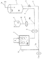
本発明の装置の実施の態様として、図1に示す装置を例示できる。図1は、本発明の装置の実施の一態様を示す図である。
図1において、原水タンク1に原水給水管1aが接続されている。原水Wはフロ−トバルブ(図示せず)を通して供給されるため原水タンク1の水位は一定に保持される。原水タンク1には原水送水管2が接続され、原水ポンプ3を介して電解槽5に接続されている。更に、塩酸タンク9から塩酸用定量ポンプ4を介して原水送水管2に合流する塩酸供給管10が、原水ポンプ3の上流箇所10aで原水送水管2に接続されている。電解槽5には殺菌剤を排出する電解処理液排出管8が接続されている。電解槽5の中は、陰陽両電極を隔離する膜が存在せず、一の室になっており電極7が設置され、各々電源6に結線されている。
【0033】
次に、前記構成を備えた装置の作用について説明する。原水Wが原水ポンプ3によって原水送水管2を通って電解槽5に通液される。比較的高濃度の塩酸Aが塩酸用定量ポンプ4によって塩酸供給管10を通じて原水Wに注入される。このようにして電解槽に通液される原水Wは一定濃度の塩酸添加原水AWとなる。次いで電解槽5内の電極7に通電して電解処理を行うが、電解槽内では陰極で還元された液と陽極で酸化された液とが常時混合しているので、pHは電解処理前の塩酸添加原水AWとほぼ同じ値である。陽極での酸化反応によって生成した塩素、次亜塩素酸、オゾン等は、電解処理液の酸性が強いこと等のために比較的安定して遊離状態で存在する傾向が強い。従って、塩酸添加原水AWは酸化作用の強い電解処理液Eとなり、電解処理液排出管8からはpHが低く、かつ酸化作用の強く、高い殺菌作用を有する殺菌剤として好適に使用し得る電解処理液Eが排出される。
【0034】
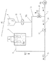
また、本発明の装置の別な実施の態様として、例えば、図2に示す装置を例示できる。図2は、本発明の装置の別な実施の態様を示す図である。図2の装置においては、構成要素の大部分は、図1と同一の符号を付して示したように、図1に示した装置と共通しており、詳細な説明は省略する。
図2の装置には、電解処理液の希釈手段が備えられている。電解処理液の希釈手段として、原水タンク1に原水送水管2とは別に、希釈水送水管12が設置されている。希釈水送水管12は、電解槽5からの電解処理液排出管8と合流点12aにおいて合流しており、合流点12aの下流には、殺菌剤送液ポンプ11が配設されている。また、希釈水送水管12には、流量調節弁13が配設されている。他の構成要素は図1の装置と同様である。
【0035】
図2の装置の作用を説明すると、電解槽5から排出された電解処理液Eが電解処理液排出管8を流れるが、合流点12aにおいては、希釈水送水管12を通じて送液された希釈水と合流し、混合されて希釈される。希釈された電解処理液は処理液排出管8を流れるが、合流点12aにおいては、希釈水送水管12を通じて送液された希釈水と合流し、混合されて希釈される。希釈された電解処理液は殺菌剤送液ポンプ11により送液され殺菌剤Edとして採取することができる。希釈水の流量は、流量調節弁13により調節することができる。
尚、図2の実施態様においては、電解槽5から排出された電解処理液Eを直ちに希釈することが可能であり、また、電解処理液Eを密閉状態で希釈できるため、電解処理液Eに含有されるガスが抜けることがないという特有の効果がある。
また、本発明の装置の別な実施の態様として、例えば、図3に示す装置を例示できる。図3は、本発明の装置の別な実施の態様を示す図である。図3の装置においては、構成要素の大部分は、図1と同一の符号を付して示したように、図1に示した装置と共通しており、詳細な説明は省略する。
図3の装置には、塩酸添加原水貯留手段14を備えており、この塩酸添加原水貯留手段14は塩酸添加原水管15により電解槽5に接続されている。電解槽5には殺菌剤を排出する電解処理液排出管8が接続されているが、電解処理液排出管8は、オリフィス16を介してエジェクタ−19に接続されており、また、エジェクタ−19には希釈水送水管12が接続している。希釈水送水管12は定流量弁16を備えており、希釈水源17に接続している。他の構成要素は図1の装置と同様である。
図3の装置の作用を説明すると、塩酸添加原水貯留手段14には、予め調製された塩酸添加原水AWが貯留されている。希釈水が希釈水源17より希釈水送水管12を通じてエジェクタ−19に流れるが(矢印Y方向)、その流量は定流量弁18により一定に制御される。エジェクタ−19が電解処理液排出管8を吸引するため、塩酸添加原水貯留手段14に貯留された塩酸添加原水AWが塩酸添加原水管15を流れ(矢印X1方向)、電解槽5に通液される。電解槽5から排出された電解処理液Eが電解処理液排出管8を流れエジェクタ−19に達し(矢印X2方向)、希釈水源17からの希釈水と混合されて希釈される。希釈された電解処理液は殺菌剤Edとして採取することができる。希釈水の流量に対する電解処理液の流量の比率は、予め電解処理液排出管8に設置されたオリフィス16により調節される。
図3の装置においては、エジェクタ−19の作用が塩酸添加原水通液手段の作用を兼ねていることになり、構造が簡便である。
次に、図3の装置を利用する態様について説明する。図3の装置により製造した殺菌剤は、例えば水洗トイレの洗浄水に添加することができる。一般に水洗トイレの便器は雑菌により汚染されやすく、しかも雑菌に由来する汚れが付着することがある。このような場合に電解槽を用いることは公知であるが、従来の電解槽には前記▲1▼〜▲3▼の問題点があるため、図3の装置を適用することにより、より望ましい水洗トイレとすることができる。
図4は、図3の装置を利用した水洗トイレを示す図である。図4において、図3と共通する構成要素には、図3と同一の符号を付して詳細な説明は省略する。
図4において、便器25には洗浄水送水管24が接続されており、洗浄水送水管24はシスタ−ン23に接続されている。シスタ−ン23には洗浄水が貯留されている。
シスタ−ン23にはフロ−トバルブ21が備えられており、フロ−トバルブ21には洗浄水送水管12aが接続され、洗浄水送水管12aの末端は、洗浄水給水源17aに接続されている。この洗浄水送水管12aに、図3の殺菌剤の製造装置20が備えられている。
図4の装置の作用を説明すると、洗浄水送水管24から便器25に洗浄水が流されると、シスタ−ン23の水位が下がる。フロ−トバルブ21のフロ−ト22の位置が下がり、フロ−トバルブ21が開栓され、洗浄水W0が洗浄水給水源17aから洗浄水送水管12aを介してシスタ−ン23に送水される。洗浄水W0はシスタ−ンの水位が回復するまで送水される。
この際、殺菌剤の製造装置20が作動して殺菌剤を製造し、殺菌剤はエジェクタ−19を介して洗浄水W0に混入される。これによって、シスタ−ン23、洗浄水送水管24、及び便器25には、殺菌された洗浄水が流れる。尚、殺菌剤の製造装置20の作動は、フロ−トバルブ21と連動させる等、種々自動化することもできる。また、前記エジェクタ−19に替えてポンプを使用しても良い。
図4の装置では、従来の電解槽のように、前記▲1▼〜▲3▼の問題点が存在しないため、製造した殺菌剤を好適に利用することができる。特に図4の装置では、シスタ−ンが存在しないタイプの水洗トイレであっても対応できる利点がある。
尚、最近流行している、便器にシャワ−が付属しており、このシャワ−により排便後の肛門を洗浄できるタイプの水洗トイレにおいては、本発明の装置により製造した殺菌剤を、シャワ−用の水として利用すれば極めて衛生的である。この場合は、シャワ−の作動と本発明の装置とが連動するように自動化すれば良い。
次に、本発明の第三の発明である殺菌処理方法の実施の態様について説明する。説明の便宜上、殺菌処理を行う装置を例示し、この装置を説明することにより殺菌処理方法の説明に替えるものとする。
本発明の殺菌処理方法は、例えば、図5に示す装置を使用することにより実施することができる。図5は、本発明の殺菌処理方法を実施するための殺菌処理装置の一例を示す図である。図5の装置は、前記図1乃至図3の装置の構成要素の一部を変更したものであり、構成要素の大部分は、図1乃至図3と同一の符号を付して示したように、図1乃至図3に示した装置と共通しており、詳細な説明は省略する。
図5において、原水送水管2の一端が原水供給源17bに接続されている。原水送水管2は、原水送水管2aと原水送水管2bに分岐しており、原水送水管2bには、殺菌処理装置30が備えられている。この殺菌処理装置30は図2に示した装置を応用したものである。原水送水管2aには流量調節弁32が、また原水送水管2bには流量調節弁31が備えられている。電解処理液排出管8は原水送水管2aと合流して原水送水管2cとなる。
図5の装置の作用を説明すると、原水送水管2には、図示しないポンプによって原水供給源17bから原水W1が流れ(矢印Y方向)、原水送水管2a及び原水送水管2bに各々分岐して流れる(各々矢印Y1方向及び矢印Y2方向)。これらの流量比は、流量調節弁31及び32によって調節される。原水送水管2bを流れる原水には、比較的高濃度の塩酸Aが塩酸供給管10を通じて注入される。次いで、電解槽に通液され、電解処理されて電解処理液排出管8から排出される(矢印X2方向)。電解処理液は、原水送水管2aを流れる原水に合流して原水送水管2cを流れる(矢印Y3方向)。これによって、原水W1は殺菌処理される。
図5の装置によれば、従来の電解槽のように、アルカリ水が生成することがなく、アルカリ水を廃棄する必要がない。また、原水送水管2bによって原水W1の一部を採取し、これを塩酸添加原水AWとして調製するため、殺菌処理後に原水W1の流量が大幅に増加することがない。
次に、図5の装置を利用する態様を説明すると、まず、飲料用水を殺菌処理して飲料水に変換する操作が例示できる。この場合は、図5における「原水供給源17b」を飲料用水の供給源とする。即ち、飲料用水の供給源17bから流れる飲料用水は、図5の装置によって殺菌処理され、飲用に好適な水となり、上水道等に供給される。
また、図5の装置の別な利用形態として、工場、家庭等で排出される廃水の殺菌処理が例示できる。この場合は、図5における「原水供給源17b」を廃水の排出源とする。即ち、廃水の排出源17bから排出される廃水を、図5の装置により殺菌処理すれば、河川、下水等に流す際に、病原菌等による環境汚染を防ぐことができる。
更に、図5の装置の別な利用形態として、図5の装置によって殺菌処理した水を凍結し、衛生的な氷を得る操作を例示できる。一般に、新鮮な魚介類を輸送する際には、鮮度を維持するために氷詰めにすることが多いが、このために使用する氷は衛生的なものが望ましい。図5の装置によって殺菌処理した水から氷を製造すれば、殺菌作用を保持しているため、衛生的であり、好適である。
更に、図5の装置の別な利用形態を説明すると、図6に示すようなク−リングタワ−冷却水の殺菌処理が例示できる。図6は、図5の殺菌処理装置をク−リングタワ−冷却水の循環管路に備えた一例を示す図である。図6において、ク−リングタワ−33と冷却設備のコンデンサ−34とは、循環管路37により接続されている。循環管路37にはポンプ35が設置されている。
また循環管路37には、前記図5の殺菌処理装置30が設置されている。更に、循環管路37には塩素濃度計36が備えられ、塩素濃度計36の出力線36aはコントロ−ラ−38に結線されている。コントロ−ラ−38の出力線4aは殺菌処理装置30の塩酸用定量ポンプ4に、また出力線6aは電源6に結線されている。
図6の装置の作用を説明すると、ポンプ35によって冷却水が循環管路37を循環するが(矢印Y方向)、冷却水の塩素濃度は塩素濃度計36によって計測されている。計測された塩素濃度の値は、出力線36aを介してコントロ−ラ−38に送信され、これに基づいてコントロ−ラ−38が最適な殺菌条件を算出し、出力線4a及び6aを介して塩酸用定量ポンプ4及び電源6を各々制御し、冷却水を殺菌することにより、雑菌が繁殖することを防止する。図6の態様においては、冷却水のpH又は有効塩素濃度を制御できる点、従って各機器の腐食が抑制できる点が、従来の電解槽を用いることに比べた有利な効果である。
更に、図5の装置の別な利用形態を説明すると、図7に示すような貯水槽の殺菌処理が例示できる。図7は、図5の殺菌処理装置を貯水槽に備えた一例を示す図である。図7においては、構成要素の大部分は、図6と同一の符号を付して示したように、図6に示した装置と共通しており、詳細な説明は省略する。
図7において、貯水槽39には循環管路37が備えられており、循環管路37には、ポンプ35、図5の殺菌処理装置30、及び塩素濃度計36が備えられている。
図7の作用を説明すると、貯水槽39内の原水W2は、ポンプ35によって循環管路37を矢印Y方向に循環する。原水W2の塩素濃度は塩素濃度計36によって計測され、図6と同様に殺菌処理装置30により殺菌処理される。即ち、貯水槽39内の原水W2を殺菌処理することができ、雑菌の繁殖状態を自由に制御することができる。この場合に、貯水槽39内の有効塩素濃度が最適値になるようにコントロ−ラ−38により制御しても良い。
尚、図7の貯水槽39としては、風呂、プ−ル、水槽、養魚用池等が例示できる。風呂に利用する場合は、循環管路37に濾過装置、加熱装置を設置すると好適であり、プ−ルに利用した場合は、水に塩素を直接吹き込む方法、水に次亜塩素酸ソ−ダを注入する方法に比して、殺菌力が強い点、設備が簡易である点、塩素ガスの取り扱いを要しない点で、有利な効果を有している。
以上に例示した全ての例において、従来の電解槽が有する前記▲1▼〜▲3▼の問題点が全て解決されていることは明らかであり、本発明が極めて有効であることが理解できる。
尚、従来の電解槽においては、原水に塩化ナトリウム等の塩類を混入して電解処理を行い、電解効率を上げることが多かったが、本発明では、塩類を含有しない塩酸添加原水であっても効率良く電解処理することができる。このように塩類を含有しない塩酸添加原水を使用した場合は、電解処理液を使用する際に塩類が固形物として析出することがないという利点がある。即ち、図6においてはクーリングタワー33内に塩類が付着することがなく、図7においては貯水槽39の壁面に塩類が付着することがない。このように、塩類を含有しない塩類添加原水を使用した場合には、本発明は、従来よりもはるかに有利な効果を奏するのである。
【0036】
次に試験例を示して本発明を詳述する。
試験例1
この試験は、矩形波交番電源により電解処理した場合の周波数と殺菌効果との関係を調べるために行った。
1)試料の調製
原水の流量を1分当たり900mlの割合に調整したこと、原水ポンプ3及び塩酸用定量ポンプ4の回転数を調節して塩酸添加原水のpHを2.4に調整したこと、並びに通電する交番電流を14Aで、周波数を0.5Hzから10Hzまで段階的に変化させたことを除き、後記する実施例3の装置を使用し、後記する実施例4と同様の方法により殺菌剤の試料を製造した。
【0037】
2)試験方法
各条件において製造した殺菌剤の殺菌効果を次の方法により試験した。各殺菌剤試料99mlに、大腸菌[東京大学医科学研究所(IID)O111株。以下同じ]を滅菌普通ブイヨン培地(栄研化学社製)50mlに1白金耳接種し、37℃で20時間培養した培養液(菌数11×108 /ml。)1mlを添加し、均一に混合し、室温で2分間放置し、混合液中の菌数(N)を常法(津郷友吉ら編、「乳業ハンドブッック」、第513〜514頁、株式会社朝倉書店、1973年)により測定した。また、殺菌剤試料の代わりに、滅菌生理食塩水を使用して同様に試験した対照の菌数(N0 )も測定した。
前記対照の菌数に対する殺菌剤試料の菌数の比(N0 /N)を算出し、その比を対数値で表現し、殺菌効果を試験した。
【0038】
3)試験結果
この結果は表1に示すとおりである。表1から明らかなとおり、周波数が5Hz以下の試料で殺菌効果が認められ、周波数が2Hz以下の試料では極めて高い殺菌効果が認められた。この結果、本発明においては、交番電流の周波数は5Hz以下、より好ましくは2Hz以下であることが判明した。尚、本発明に係る殺菌剤について、他の装置及び他の製造方法についても同様に試験を行ったが、ほぼ同様の結果が得られた。
【0039】
【表1】

試験例2
この試験は、直流電源により電解処理した場合の電解電気量と殺菌効果との関係を調べるために行った。
1)試料の調製
原水の流量を1分当たり900mlの割合に調整したこと、原水ポンプ3及び塩酸用定量ポンプ4の回転数を調節して塩酸添加原水のpHを2.6に調整したこと、並びに通電する電流を直流電流として電解電気量を、表2に示すとおり0.27c/mlから1.3c/mlまで段階的に変化させたことを除き、後記する実施例4と同様の方法により殺菌剤の試料を製造した。
【0041】
2)試験方法
各殺菌剤試料の殺菌効果を試験例1と同一の方法により試験した。
【0042】
3)試験結果
この結果は表2に示すとおりである。表2から明らかなとおり、電解電気量が0.4c/ml以上の試料で殺菌効果が認められ、0.8c/ml以上の試料では極めて高い殺菌効果が認められた。この結果から、本発明の電解処理においては、電解電気量の値が0.4c/ml以上、より好ましくは0.8c/ml以上であることが判明した。尚、本発明に係る殺菌剤について、他の装置及び他の製造方法についても同様に試験を行ったが、ほぼ同様の結果が得られた。
【0043】
【表2】
試験例3
この試験は、殺菌剤の有効塩素濃度と殺菌効果との関係を調べるために行った。
1)試料の調製
原水の流量を1分当たり470mlの割合に調整したこと、通電する電流を直流電流として電解電気量を段階的に変化させて、有効塩素濃度を変化させたことを除き、後記する実施例4と同一の方法により殺菌剤の試料を製造した。
得られた試料を適量希釈し、有効塩素濃度をヨウ素法(日本薬学会編、「衛生試験法・注解」、第1066頁、金原出版株式会社、1990年)により定量して、有効塩素濃度が0.05ppmから6.4ppmまで段階的に変化した一群の試料を得た。なお、各試料のpHは、約5に揃えた。
【0045】
2)試験方法
各殺菌剤試料の殺菌効果を試験例1と同一の方法により試験した。
【0046】
3)試験結果
この結果は表3に示すとおりである。表3から明らかなとおり、有効塩素濃度が0.1ppm未満の試料では殺菌効果が低減している。この結果、本発明の製造方法においては、殺菌剤は有効塩素濃度が0.1ppm以上である状態で使用することが望ましいことが判明した。尚、本発明に係る殺菌剤について、他の装置及び他の製造方法についても同様に試験を行ったが、ほぼ同様の結果が得られた。
【0047】
【表3】
【実施例】
次に、実施例を示して本発明を詳述するが、本発明は以下の実施例によって何ら限定されるものではない。
実施例1
本発明の製造装置の一実施例を図1に示す。図1に示した装置は、次の各機器により構成されている。図1において、各構成要素及びその作用は、前記の如く、その実施の態様として説明したとおりである。
実施例2
この実施例は、前記実施例1の製造装置を使用した殺菌剤の製造方法の一例であり、その内容を図1に基づいて説明する。
まず、予備的に次のとおり装置を作動させた。原水(井水)を貯留した原水タンク1から原水ポンプ3により電解槽5に1時間当たり1000lの割合で原水を供給し、食品添加物規格の塩酸(純正化学社製。36.46%)を貯留した塩酸タンク9から塩酸用定量ポンプ4により連続的に原水に添加し、塩酸添加原水を試験的に調製し、調製した塩酸添加原水を採取し、pHを測定し、塩酸用定量ポンプ4の回転数を調節し、塩酸添加原水のpHを2.5に調整した。
【0050】
次に、前記予備試験により設定された条件に基づいて原水を貯留した原水タンク1から原水ポンプ3により電解槽5に1時間当たり1000lの割合で原水を供給し、食品添加物規格の塩酸(純正化学社製。36.46%)を貯留した塩酸タンク9から塩酸用定量ポンプ4により連続的に原水に添加し、pH2.5の塩酸添加原水を調製し、電解槽5に連続的に通液し、塩酸添加原水に浸漬した電極7に周波数2Hzの交番電流を、塩酸添加原水1ml当たり0.8クーロンの割合で通電し、塩酸添加原水を電解処理し、電解処理液排出管8から電解処理液を採取し、pH2.5及び酸化還元電位1130mVの殺菌剤を1時間当たり約1000lの割合で連続的に得た。
得られた殺菌剤を試験例1と同一の方法により試験した結果、log(N0 /N)は7.0以上であり、顕著な殺菌効果が認められた。
【0051】
実施例3
本発明の製造装置の別な実施例について説明する。各構成要素の態様は、前記実施例1と同一であり(各構成要素には図1と共通の符号を付して図示を省略する)、本実施例の装置は、次の各機器を具えている。
【0052】
実施例4
この実施例は、前記実施例3の装置を使用した殺菌剤の製造方法の一例であり、その内容を図1に基づいて説明する。
まず、予備的に次のとおり装置を作動させた。原水(井水)を貯留した原水タンク1から原水ポンプ3により電解槽5に1時間当たり130lの割合で原水を供給し、試薬1級の塩酸(関東化学社製)を貯留した塩酸タンク9から塩酸用定量ポンプ4により連続的に原水に添加し、塩酸添加原水を試験的に調製し、調製した塩酸添加原水を採取し、pHを測定し、塩酸用定量ポンプ4の回転数を調節し、塩酸添加原水のpHを1.45に調整した。
【0053】
次に、前記予備試験により設定された条件に基づいて原水を貯留した原水タンク1から原水ポンプ3により電解槽5に1時間当たり130lの割合で原水を供給し、試薬1級の塩酸(関東化学社製)を貯留した塩酸タンク9から塩酸用定量ポンプ4により連続的に原水に添加し、pH1.45の塩酸添加原水を調製し、電解槽5に連続的に通液し、塩酸添加原水に浸漬した電極7に直流電流を、電流値21A、電圧6.3Vで通電し、塩酸添加原水を電解処理し、電解処理液排出管8から電解処理液を採取し、pH1.45及び酸化還元電位1170mVの殺菌剤を得た。
また、得られた殺菌剤を井水で10倍に希釈し、pH2.55、酸化還元電位1135mVの殺菌水を得た。
得られた殺菌剤及び殺菌水を試験例1と同一の方法により試験した結果、両者ともlog(N0 /N)が7.0以上であり、共に顕著な殺菌効果が認められた。
また、この実施例4で得られた殺菌剤を井水で20倍に希釈し、pH5.1の殺菌水を得た。この殺菌水の有効塩素濃度は3.0ppmであった。この20倍に希釈した殺菌水を試験例1と同一の方法により試験した結果、log(N0 /N)が7.0以上であり、顕著な殺菌効果が認められた。
更に、前記10倍に希釈した殺菌水と20倍に希釈した殺菌水とを各々容器に入れ、室温で遮光した状態で3日間保存した後、各々の殺菌効果を試験例1と同一の方法により試験した結果、log(N0 /N)は、10倍に希釈したものは5.3であり、20倍に希釈したものは7.0以上であった。従って、希釈後のpHが5.1である方が、殺菌効果をより長く維持できることが判明した。
更に、希釈の度合を変更し、種々のpHの殺菌水について、同様の実験を行ったところ、希釈後のpHが7.0以下であれば、殺菌効果の経時劣化が少なく、特にpHが3.5以上6.5以下の範囲が好ましいことが判明した。
【0054】
実施例5
本発明の装置の別な実施例について説明する。本発明の装置の別な実施例を図2に示す。図2の装置の各構成要素の態様は、図1と共通の符号を付して示したように、前記図1と同一であり、その詳細な説明を省略する。
図2に示した装置の各機器は、基本的には、前記実施例3と同一の機器を使用しており、更に、次の機器を追加している。
殺菌剤送液ポンプ11・・・イワキ社製遠心ポンプ、MD−30R
流量調節弁13・・・・・・ト−ワテクノ社製、手動式
図2において、各構成要素及びその作用は、前記の如く、その実施の態様として説明したとおりである。
尚、殺菌剤送液ポンプ11として遠心ポンプを使用しているため、電解処理水と希釈水とを混合後に攪拌することができる。
【0055】
実施例6
この実施例は、前記実施例5の装置を使用した殺菌剤の製造方法の一例であり、その内容を図2に基づいて説明する。
まず、予備的に次のとおり装置を作動させた。原水(井水)を貯留した原水タンク1から原水ポンプ3により電解槽5に1時間当たり130lの割合で原水を供給し、前記実施例4と同様の手順により、塩酸添加原水のpHを1.45に調整した。
【0056】
次に、前記実施例4と同様の手順により、pH1.45の塩酸添加原水を調製して電解槽5に連続的に通液し、塩酸添加原水を電解処理した。
更に、遠心ポンプ11を作動させて流量調節弁13を調節し、1時間あたり1170lの希釈水を原水タンク1から合流点12aに送液し、電解処理液排出管8から排出される電解処理液と混合して希釈した。希釈水と電解処理液との流量比率は9対1である。そして、pH2.55、酸化還元電位1135mVの殺菌剤を得た。
得られた殺菌剤を試験例1と同一の方法により試験した結果、log(N0 /N)が7.0以上であり、顕著な殺菌効果が認められた。
【0057】
実施例7
本発明の装置の別な実施例について説明する。本発明の装置の別な実施例を図3に示す。図3の装置の各構成要素及びその作用は、前記の如く、その実施の態様として説明したとおりである。
【0058】
実施例8
この実施例は、前記実施例7の製造装置を使用した殺菌剤の製造方法の一例であり、その内容を図3に基づいて説明する。
食品添加物規格の塩酸(純正化学社製。36.46%)を蒸留水で希釈し、0.1mol/lの塩酸添加原水を調製し、容器14に貯留した。
希釈水源17である水道蛇口を開き、エジェクタ−19に希釈水を流し、定流量弁18によって流量を調節し、エジェクタ−19出口流量を2.5l/minに調節した。このとき、塩酸添加原水管15、電解槽5、電解処理液排出管8を介して流れる塩酸添加原水及び電解処理液の流量は、50ml/minであった。
電解槽5の電極7に1.5Aの直流電流を通電し、塩酸添加原水を電解処理したところ、pH3.4の殺菌剤を、2.5l/minの能力で連続的に得ることができた。
得られた殺菌剤を試験例1と同一の方法により試験した結果、顕著な殺菌効果が認められた。
実施例8において調製した0.1mol/lの塩酸添加原水は、取り扱いの安全性が高く、家庭において使用しても安全である。
【0059】
【発明の効果】
以上詳記したとおり、本発明は、陰陽両極間に隔膜が存在しない電解槽に、塩酸添加原水を通液し、塩酸添加原水に浸漬した陰陽両極に通電し、上記塩酸添加原水を電解処理し、電解処理液を採取することを特徴とする高い殺菌作用を有する電解処理液からなる殺菌剤の製造方法、その製造装置及びその方法により製造された殺菌剤に係るものであり、本発明により奏せられる効果は次のとおりである。
1)本発明の製造方法又は装置によれば、供給した塩酸添加原水の全量を殺菌剤として利用することができるので、陰極から生成するアルカリイオン水を廃棄する必要がなく、電力及び水の使用量が低減される。
2)本発明の製造方法又は装置によれば、電解槽に隔膜を使用しないので、電解槽及び付帯設備が簡単な構造となり、隔膜の保守管理費が軽減される。
3)本発明の製造方法又は装置によれば、低いpHの塩酸添加原水を電解処理した後に希釈すれば良いため、電解処理する量が少量で良く、この点でも電解槽及び付帯設備の小型化、低価格化、及び消費電力の低減が可能である。
4)本発明の製造方法又は装置によれば、電極へのスケ−ル付着が防止できるので、長時間運転が可能であり、製造費が安価になる。
5)本発明の殺菌剤は、高い殺菌作用を有する電解処理液からなり、殺菌効果が高く、食品の製造器具・設備、医薬品の製造器具・設備、医療器具、医療関係者の手指の消毒等に効果的に使用できる。
6)本発明の殺菌処理方法は、極めて広範囲の原水に適用することができ、生産活動、サ−ビス活動、日常生活等の様々な分野で応用することができる。
【図面の簡単な説明】
【図1】本発明の装置の一実施例を示す図である。
【図2】本発明の装置の別な実施例を示す図である。
【図3】本発明の装置の別な実施例を示す図である。
【図4】図3の装置を利用した水洗トイレを示す図である。
【図5】本発明の殺菌処理方法を実施するための殺菌処理装置の一例を示す図である。
【図6】図5の殺菌処理装置をク−リングタワ−冷却水の循環管路に備えた一例を示す図である。
【図7】図5の殺菌処理装置を貯水槽に備えた一例を示す図である。
【符号の説明】
1 原水タンク
1a 原水給水管
2 原水送水管
3 原水ポンプ
4 塩酸用定量ポンプ
5 電解槽
6 電源
7 電極
8 電解処理液排出管
9 塩酸タンク
10 塩酸供給管
11 殺菌剤送液ポンプ
12 希釈水送水管
12a 合流点
13 流量調節弁
14 容器
15 塩酸添加原水管
16 オリフィス
17 希釈水源
18 定流量弁
19 エジェクタ−
20 殺菌剤の製造装置
21 フロ−トバルブ
22 フロ−ト
23 シスタ−ン
24 洗浄水送水管
25 便器
30 殺菌処理装置
31 流量調節弁
32 流量調節弁
33 ク−リングタワ−
34 コンデンサ−
35 ポンプ
36 塩素濃度計
37 循環管路
38 コントロ−ラ−
39 貯水槽
A 塩酸
W 原水
AW 塩酸添加原水
E 電解処理液
Ed 殺菌剤
W0 洗浄水
W1 原水
W2 原水[0001]
BACKGROUND OF THE INVENTION
The present invention relates to a method for producing a bactericide comprising an electrolytic treatment liquid having a high bactericidal action, characterized by electrolyzing hydrochloric acid-added raw water (hereinafter sometimes referred to as electrolytic treatment), and a production apparatus thereof, The present invention relates to a disinfectant produced by the method and a disinfecting method of raw water.
More specifically, the present invention is characterized in that the electrolytic treatment solution is collected without being separated into anodic water and cathodic water by electrolytic treatment of hydrochloric acid-added raw water in an electrolytic cell in which no diaphragm exists between the positive and negative electrodes. The present invention relates to a method for producing a bactericide comprising an electrolytic treatment solution having a high bactericidal effect, a bactericidal agent produced by the method, and a raw water sterilization method using the method.
In the present specification, the percentage display is a value by weight unless otherwise specified.
[0002]
[Prior art]
Conventionally, a method for obtaining acidic water or alkaline ionized water by electrolyzing water is known. In general, when water is electrolyzed for the purpose of obtaining acidic water or alkaline ionized water, an electrolytic cell is used (supervised by Kunihiko Watanabe et al., “New Water Science and Utilization Technology”, pages 200 to 207, Science Forum Lam Company, 1992). A conventional electrolytic cell has an electrode composed of an anode and a cathode inside, and has a structure in which the anode and the cathode are separated by a diaphragm and divided into two chambers, an anode chamber and a cathode chamber. Water whose electroconductivity was increased by adding a small amount of electrolyte such as sodium chloride to the tank was supplied, and direct current was applied to the electrodes to electrolyze the water.
[0003]
To explain the operation of a conventional electrolytic cell, first, water to be electrolyzed (hereinafter referred to as raw water) is sent to the anode chamber and the cathode chamber of the electrolytic cell by a pump or the like and electrolyzed. In the anode chamber, the raw water is oxidized and part of the hydroxide ions is removed as oxygen gas, so that the water discharged from the anode chamber has a high oxidation-reduction potential and is acidic, so-called acidic water. . On the other hand, in the cathode chamber, the raw water is subjected to a reducing action, and part of the hydrogen ions is removed as hydrogen gas. Therefore, the water discharged from the cathode chamber has a low oxidation-reduction potential and exhibits alkalinity. Become. Acidic water has a bactericidal action and is used for sterilizing and washing instruments, fingers and the like in the food industry and medical fields, and alkaline ionized water is used for drinking.
Thus, in recent years, acidic water having a bactericidal effect is produced by electrolytic treatment and used as a kind of bactericidal agent.
On the other hand, various raw waters used in our daily lives, factory facilities, etc. generally require sterilization treatment, and more effective sterilization treatment methods are always expected. In some cases, an electrolytic cell was used.
For example, cooling water is circulated between a condenser installed in a cooling facility in a factory or the like and a cooling tower attached thereto, and heat exchange is performed. It became easy and hygienic. Accordingly, attempts have been made to prevent the propagation of germs by installing an electrolytic cell in the cooling water circulation line (see, for example, JP-A-5-87489). In addition, the washing toilet stern is provided with an electrolytic bath to treat the washing water flowing through the toilet (see, for example, JP-A-3-33332), the electrolytically treated water in the electrolytic bath is frozen, and the ice state (See, for example, JP-A-7-218062). Further, a technique for providing an electrolytic tank in a water storage tank such as a bath or a pool and sterilizing the stored water is also known (see, for example, Japanese Patent Laid-Open No. 7-256262).
[0004]
Various improved techniques have been announced for the conventional electrolytic treatment method (hereinafter referred to as prior art 1). For example, in the electrolytic treatment, a technique for effectively using water on the unused side of acid water and alkali ion water has been reported. Further, the following conventional techniques are known as techniques for reducing the adhesion of the scale to the cathode. That is, a means for switching the alkali neutralizing agent and the acidic neutralizing agent to the cathode chamber and the anode chamber of the electrolytic cell is provided so as to be switchable, and the other one of the generated acidic water and alkaline ionized water is neutralized and the other one is used. And a method for preventing the adhesion of the scale to the cathode by reversing the polarity of the electrode of the electrolytic cell in a timely manner and reversing the functions of the cathode chamber and the anode chamber (Japanese Patent Laid-Open No. Hei 4-99295). Technology 2) is known.
[0005]
In order to solve the same problem, the present inventors have developed the following technique and have already filed a patent application. That is, a technology has been completed in which hydrochloric acid is added to the raw water in the cathode chamber of the electrolytic cell to make it acidic in advance, and alkali ion water close to neutrality is generated in the negative electrode chamber and fed back to the raw water ( Japanese Patent Application No. 7-63384, Prior Art 3).
Furthermore, a technique is also known in which salt water is added after filtering raw water, and electrolytic treatment is performed by a conventional method to obtain acidic water having a pH of 1.5 to 3.3, which is used as a bactericidal agent (Japanese Patent Application No. Hei. 7-274922. Prior art 4).
[0006]
However, the
(1) Calcium dissolved in the raw water adheres as a scale to the surface of the cathode and reduces the efficiency of the electrolytic treatment, making it difficult to operate for a long time.
(2) Both sides of the diaphragm are exposed to acids and alkalis, and electricity flows, so that the diaphragm is consumed very much and the running cost becomes expensive.
{Circle around (3)} When only acidic water is desired to be taken out as a bactericidal agent, alkaline ion water is discarded, and water corresponding to the alkali ion water and electric power are wasted.
[0007]
On the other hand, in the
The prior art 3 has the disadvantage that it cannot solve the problem {circle around (2)} of the prior art, that is, the high running cost.
Furthermore, in the said prior art 4, since alkaline ion water is produced | generated simultaneously with acidic water (bactericidal agent), the loss of electric power and water is large, and in order to obtain low pH acidic water from neutral raw water, a large amount The apparatus has a drawback that it requires electric power and the running cost is high as a whole, and the apparatus tends to be complicated, for example, a separate facility for filtering raw water is required to prevent the scale from adhering to the cathode.
Also, in the conventional method of sterilizing raw water using an electrolytic cell, the conventional electrolytic cell has the above problems (1) to (3), so that there is a satisfactory sterilizing method after all. I did not.
[0008]
[Problems to be solved by the invention]
In view of the prior art, the present inventors conducted extensive research on a method for producing a new bactericide using electrolysis, and as a result, passed hydrochloric acid-added raw water through an electrolytic cell in which no diaphragm was present between the positive and negative electrodes. The sterilization effect of the electrolytic treatment solution is dramatically improved by electrolytic treatment of the hydrochloric acid-added raw water, and the electrolytic treatment solution after the electrolytic treatment can be suitably used as an excellent sterilizing agent having a high sterilization effect. The present invention has been completed.
[0009]
The object of the present invention is to solve the above-mentioned problems of the prior art and eliminate the need for discarding alkaline ionized water, that is, a new sterilization obtained as a sterilizing agent having a high sterilizing effect in which the total amount of raw hydrochloric acid added raw material is high Providing a method for producing an antibacterial agent, providing a new method for producing an antibacterial agent that does not require a diaphragm for an electrolytic cell, has a simple apparatus structure, and can obtain a large amount of an antibacterial agent with a small-scale apparatus Another object of the present invention is to provide a production method capable of easily and inexpensively producing a bactericidal agent having a high bactericidal effect, capable of operating for a long time without worrying about scale adhesion.
Another object of the present invention is to provide an apparatus for easily producing a bactericidal agent having a high bactericidal effect.
Furthermore, another object of the present invention is to provide a bactericidal agent comprising an electrolytic treatment liquid having a high bactericidal action produced by the above method.
Furthermore, the other object of this invention is to provide the method of disinfecting raw | natural water using the said method.
[0010]
[Means for Solving the Problems]
The first invention of the present invention for solving the above problems is an electrolytic cell in which no diaphragm exists between the positive and negative electrodes, Contains no sodium chloride From the electrolytic treatment solution having a high bactericidal action, characterized by passing the hydrochloric acid-added raw water through, passing current through the negative and positive electrodes immersed in the hydrochloric acid-added raw water, electrolytically treating the hydrochloric acid-added raw water, and collecting the electrolytic treatment solution A method for producing a bactericide, Contains no sodium chloride The flow of hydrochloric acid-added raw water, the electrolytic treatment, and the collection of the electrolytic treatment solution are performed continuously. Contains no sodium chloride Prepare hydrochloric acid-added raw water by diluting hydrochloric acid with a hydrochloric acid molar concentration of 0.001 mol / l or more and 6.4 mol / l or less, collecting the electrolytic treatment solution after dilution with water, collecting the electrolytic treatment solution Is performed in a range of effective chlorine concentration of 0.1 ppm or more, energization is performed with an alternating current of frequency exceeding 0 Hz and 5 Hz or less, energization, Contains no sodium chloride Performed at a rate of electricity not lower than 0.4 and not higher than 6.0 kl per 1 ml of hydrochloric acid-added raw water; and Contains no sodium chloride It is also desirable that the hydrochloric acid-added raw water has a pH of 0.5 to 3.0.
[0011]
A second invention of the present invention for solving the above problems is a bactericidal agent produced by the first invention.
The third invention of the present invention for solving the above-mentioned problems is Contains no sodium chloride Add hydrochloric acid to the raw water Contains no sodium chloride A raw water-added raw water is prepared, and an electrolytic treatment solution is collected by carrying out the method of the first invention, and the collected electrolytic treatment solution is obtained as a sterilization raw water. . In addition, the third invention, Contains no sodium chloride Add hydrochloric acid to a part of the raw water Contains no sodium chloride It is also possible to take a mode in which hydrochloric acid-added raw water is prepared, the electrolytic treatment solution is collected by carrying out the method of the first invention, and the collected electrolytic treatment solution is returned to the raw water.
The fourth invention of the present invention for solving the above-mentioned problems is an electrolytic cell provided with a positive and negative electrode not separated by a diaphragm, and the electrolytic cell. Contains no sodium chloride Hydrochloric acid added to raw water that passes through raw water and raw water that passes through the water feeding means And hydrochloric acid-added raw water that does not contain sodium chloride An apparatus for producing a bactericidal agent comprising an electrolytic treatment liquid having a high bactericidal action, characterized by comprising a hydrochloric acid addition means for discharging and a discharge pipe for discharging the electrolytic treatment liquid from the electrolytic cell. In addition, the fourth invention of the present invention is an electrolytic cell provided with a positive and negative electrode not separated by a diaphragm, Contains no sodium chloride Hydrochloric acid-added raw water storage means for storing hydrochloric acid-added raw water; Contains no sodium chloride An apparatus for producing a bactericidal agent comprising an electrolytic treatment liquid having a high bactericidal action, comprising a hydrochloric acid-added raw water passage means for passing hydrochloric acid-added raw water and a discharge pipe for discharging the electrolytic treatment liquid from the electrolytic cell It is also possible for the discharge pipe to include an electrolytic treatment liquid diluting means for mixing and diluting the electrolytic treatment liquid with water.
[0012]
DETAILED DESCRIPTION OF THE INVENTION
Next, although this invention is explained in full detail, the manufacturing method of the disinfectant which is 1st invention of this invention is demonstrated first.
In the first invention of the present invention, the hydrochloric acid-added raw water is defined as a solution in which hydrochloric acid is added or an aqueous solution in which a chemical substance is dissolved, and hydrochloric acid is added. For this purpose, it is desirable to use hydrochloric acid-added raw water obtained by adding a relatively high concentration of hydrochloric acid to water. In other words, it is desirable to use hydrochloric acid-added raw water containing only hydrogen chloride. In this case, when the concentration of hydrochloric acid is too high, an irritating odor is felt due to the generation of hydrogen chloride gas, and the surrounding members may corrode due to the influence. The concentration of should not be too high. Actually, a prescribed amount of hydrochloric acid (36.46% manufactured by Junsei Chemical Co., Ltd.), a food additive standard, was taken into a 500 cc beaker and gradually diluted with a predetermined amount of pure water to confirm the presence of an irritating odor. When the molar concentration of hydrochloric acid was 9.5 mol / l, 7.7 mol / l, 7.0 mol / l, an irritating odor was felt, but at 6.4 mol / l, the irritating odor was not felt, and the concentration was 6.0 mol. When it was lower than 1 / l, there was no irritating odor. Therefore, in the present invention, the molar concentration of hydrochloric acid for preparing hydrochloric acid-added raw water is preferably 6.4 mol / l or less. As will be described later, the hydrochloric acid molar concentration of the hydrochloric acid-added raw water after preparation with hydrochloric acid is preferably 0.001 mol / l or more, and naturally the molar concentration of hydrochloric acid as a raw material is preferably 0.001 mol / l or more. . That is, 0.001 mol / l hydrochloric acid may be used as hydrochloric acid-added raw water without being particularly diluted.
Hydrochloric acid-added raw water is passed from the raw water tank through the raw water supply pipe to an electrolytic cell having no diaphragm by a raw water pump. The raw water supply pipe is mixed with a predetermined amount of hydrochloric acid from the hydrochloric acid tank by a hydrochloric acid pump, and the pH of the raw water is adjusted to 0.5 to 3.0, preferably pH 0.8 to 3.0, and hydrochloric acid-added raw water is prepared. And passed through an electrolytic cell without a diaphragm. In addition, the hydrochloric acid-added raw water prepared in advance may be passed as it is. The means for passing liquid can be selected as appropriate.
[0013]
In the electrolytic cell, both the yin and yang electrodes are arranged without being separated by the membrane, and both the yin and yang electrodes are immersed in the hydrochloric acid-added raw water, energized, and the hydrochloric acid-added raw water is subjected to electrolytic treatment. For energization, an alternating current or direct current having a frequency exceeding 0 Hz and not exceeding 5 Hz, preferably exceeding 0 Hz and not exceeding 2 Hz, is applied to 0.4 to 6.0 coulombs per ml of hydrochloric acid-added raw water, preferably 0.8 to 3.0. Performed at the rate of coulombs.
The electrolytic treatment liquid can be taken out from the electrolytic tank through the electrolytic treatment liquid discharge pipe and used as a sterilizing agent as it is or diluted with water.
[0014]
As described in the prior art, an electrolytic cell for electrolyzing ordinary water has a structure in which an anode and a cathode are separated by a diaphragm. In general, not only electrolysis of water but electrolysis is often performed for the purpose of separating various products from a solution, and for this purpose, an electrolytic cell with a diaphragm is usually used. However, in the present invention, since the electrolytic treatment is performed for the purpose of changing the properties of the hydrochloric acid-added raw water, there is no need to separate the liquid produced at the anode and the liquid produced at the cathode, and an electrolytic cell having no diaphragm is used. To get.
[0015]
The reason why the sterilization effect of the electrolytic treatment solution is remarkably improved by electrolytic treatment of the hydrochloric acid-added raw water in an electrolytic cell having no diaphragm is estimated as follows. By performing the electrolytic treatment, chlorine ions are oxidized on the anode surface and converted to hypochlorous acid. As a result, a liquid having a high bactericidal action is generated.
[0016]
On the other hand, hydrogen gas is generated on the surface of the cathode and the pH becomes high, but in the electrolytic cell used in the production method of the present invention, since there is no diaphragm between the anode chamber and the cathode chamber, both waters are mixed and pH is increased. Is slightly increased due to the change of part of hydrochloric acid to hypochlorous acid, but after all, the bactericidal action generated at the anode remains as it is in the electrolytic treatment liquid, and all the raw water added with hydrochloric acid has a high bactericidal action. Presumed to be an electrolytic treatment solution.
[0017]
Next, preferred embodiments of the first invention of the present invention will be described.
In the production method of the present invention, it is also possible to perform electrolytic treatment continuously. That is, the hydrochloric acid-added raw water is continuously passed through the electrolytic bath, the electrolytic treatment is continuously performed, and the electrolytic treatment solution is continuously taken out. Thereby, a lot of fungicides can be manufactured.
[0018]
In the production method of the present invention, the electrolytic treatment solution may be collected after being diluted with water. That is, after the hydrochloric acid-added raw water having a low pH is subjected to electrolytic treatment in advance, the electrolytic treatment solution can be diluted with water to obtain a bactericide having a desired concentration. In general, when the pH of the hydrochloric acid-added raw water is low, the electrical resistance during the electrolytic treatment is reduced, and the electrolytic treatment can be performed at a lower voltage, and the amount of electric power used can be reduced. Moreover, if a small amount of hydrochloric acid-added raw water having a low pH is subjected to electrolytic treatment and then diluted, the amount of liquid to be electrolytically treated is small, so that a large amount of bactericidal agent can be obtained with a small apparatus.
In this case, as described in Test Examples below, when the effective chlorine concentration of the electrolytic treatment solution after dilution is reduced to less than 0.1 ppm, the bactericidal effect decreases. Therefore, the dilution is preferable in terms of the bactericidal effect if the effective chlorine concentration of the electrolytic treatment solution after dilution is within a range of 0.1 ppm or more. In general, the effective chlorine concentration of the electrolytic treatment solution depends on the current value at the time of energization, but in any case, the range in which the effective chlorine concentration is 0.1 ppm or more is desirable for the bactericide.
Further, when paying attention to pH, the pH of the diluted electrolytic treatment solution is preferably 7.0 or less, and particularly preferably in the range of pH 3.5 or more and 6.5 or less. That is, if the pH of the electrolytic treatment solution after dilution is in such a range, free hypochlorous acid can be present relatively stably in the solution.
[0019]
Further, in the production method of the present invention, a direct current can be applied in the same manner as in the prior art during the electrolytic treatment. However, even in this case, the electrolytic cell of the present invention has an advantage that the scale adheres less to the cathode surface than the conventional electrolytic cell. This is because there is no diaphragm in the electrolytic cell of the present invention, so the anode water and the cathode water are mixed and the pH of the hydrochloric acid-added raw water is low, so that the pH of the cathode surface is prevented from becoming high. Because it is.
[0020]
However, in the manufacturing method of the present invention, it is desirable to apply an alternating current during the electrolytic treatment. The reason is that there is no diaphragm in the electrolytic cell used in the production method of the present invention, so the negative and positive electrodes can be reversed properly. However, if an alternating current is applied, the negative and positive electrodes are periodically reversed. As a result, scale adhesion to the cathode surface can be effectively suppressed rather than direct current.
The alternating current is a current in which the positive and negative electrodes are periodically reversed, and the current waveform is not particularly limited. However, as described in the examples below, if the rectangular wave is used, the negative and positive electrodes are instantaneously It is preferable because it reverses.
[0021]
In the manufacturing method of the present invention, the frequency of the alternating current to be energized is preferably more than 0 Hz and 5 Hz or less. The reason for this is that when the frequency of the alternating current is too high, there is no reaction even if the electrolytic treatment is performed, and it is desirable to use an alternating current of 5 Hz or less, particularly 2 Hz or less, as described later in the test examples. The range of “frequency exceeds 0 Hz” does not include 0 Hz, but an alternating current with a frequency of 0 Hz means a direct current.
[0022]
In the production method of the present invention, electrolytic treatment is carried out with an electric quantity of 0.4 to 6.0 krons per ml of hydrochloric acid-added raw water (hereinafter, the unit of the number of coulombs per ml of hydrochloric acid-added raw water is expressed as a unit). c / ml)).
As described in the test examples below, when electrolytic treatment is performed with an electric quantity of 0.4 cron or more per 1 ml of hydrochloric acid-added raw water, the sterilizing effect of the sterilizing agent is increased, and the electric quantity is 0.8 cron or more. If it exists, since it will have a stronger bactericidal action, it is preferable.
Further, when the amount of electricity exceeds 6.0 c / ml, the effect of the electrolytic treatment becomes higher than necessary, and the waste of power increases. That is, the amount of gas such as chlorine gas, hydrogen gas, oxygen gas, etc. increases, but the sterilizing effect of the electrolytic treatment liquid itself is not improved, and the tendency to waste power is increased. Accordingly, the amount of electricity is preferably 6.0 c / ml or less.
[0023]
In the production method of the present invention, hydrochloric acid-added raw water having a pH of 0.5 to 3.0 is used. If the pH of the hydrochloric acid-added raw water is 3.0 or less, there is an advantage that the electric resistance during the electrolytic treatment is reduced and the electrolytic treatment can be performed at a lower voltage. However, when the pH is extremely low, the sterilizing effect of the electrolytic treatment liquid is not improved for an increase in the amount of gas such as chlorine, hydrogen, oxygen, etc. during the electrolytic treatment, resulting in a waste of electric power. Therefore, it is desirable that the pH of the hydrochloric acid-added raw water is at least 0.5 or more, preferably 0.8 or more. The pH of the hydrochloric acid-added raw water is particularly important because it affects efficiency and the like during electrolytic treatment.
In terms of the concentration of the hydrochloric acid-added raw water, the hydrochloric acid molar concentration of the hydrochloric acid-added raw water is preferably 0.001 mol / l or more and 1 mol / l or less.
In addition, when the method of the present invention is carried out at home, factory, canteen, etc., it is complicated to prepare hydrochloric acid-added raw water from hydrochloric acid having a high concentration. Therefore, it is preferable to use hydrochloric acid-added raw water prepared in advance. In this case, if the hydrochloric acid molar concentration of the hydrochloric acid-added raw water is 0.05 mol / l or more and 0.2 mol / l or less, there is little waste of electric power in the range where the bactericidal effect can be secured, and if direct current is used temporarily However, it is suitable because there is little scale adhesion to the cathode surface.
[0024]
2nd invention of this invention is the disinfectant manufactured by the said manufacturing method. Since the bactericidal agent of the present invention uses hydrochloric acid-added raw water as a starting material, it has the characteristics that it does not exhibit a particularly unpleasant taste or odor other than acidity, and there is no residue after drying. Therefore, it is particularly suitable to use when sterilizing pipes, filling devices, containers and the like in the fields of food industry, pharmaceutical industry and the like. The disinfectant of the present invention produced by the above production method is preferably diluted with water, and the pH after dilution is adjusted to 7.0 or less, particularly preferably pH 3.5 to 6.5.
A third invention of the present invention is a method for sterilizing raw water using the method of the first invention.
The first invention of the present invention can be used as a raw water sterilization method. In the present invention, raw water specifically means an aqueous solution in which water or a chemical substance is dissolved, for example, an aqueous solution or suspension having a total solid content of 300 ppm or less, but also a liquid or sterilization requiring sterilization treatment. It can also be said that it is desirable to perform the treatment.
If hydrochloric acid is added to such raw water to prepare hydrochloric acid-added raw water and the electrolytic treatment of the first invention of the present invention is performed, the produced electrolytic treatment liquid can be regarded as sterilized raw water. Also, hydrochloric acid-added raw water is prepared by adding hydrochloric acid to a part of the raw water, and similarly, the electrolytic treatment of the first invention of the present invention is performed to collect the electrolytic treatment solution, and the collected electrolytic treatment solution is used as raw water. A mode of returning may be used.
The method of the third invention of the present invention does not generate alkaline water as in the prior art, and does not require disposal of alkaline water. Therefore, according to the third invention, sterilization can be performed without discarding raw water at all. That is, it can be said that it is a sterilization method that solves the problems (1) to (3) by the conventional electrolytic cell.
As described above, in the third invention of the present invention, the alkaline water can be sterilized without being discarded, so that the application range is extremely wide and it can be used for sterilization of various liquids. The raw water in the third invention of the present invention includes drinking water, various waste waters, cooling water for cooling towers, water used as a raw material for ice, washing water for toilets, baths, pools, aquariums, fish farms However, it is not limited to these. A specific embodiment of the third invention of the present invention will be described later.
[0025]
A fourth invention of the present invention is the bactericide manufacturing apparatus, comprising at least an electrolytic cell in which negative and positive electrodes not separated by a diaphragm are disposed, a water supply means for passing raw water through the electrolytic tank, and the water supply means Hydrochloric acid addition means for adding hydrochloric acid to the raw water that is passed through, and a discharge pipe for discharging the electrolytic treatment liquid from the electrolytic cell.
The electrolytic cell of the present invention includes a container and both positive and negative electrodes, and there is no membrane that separates the negative and positive electrodes. The container constituting the electrolytic cell has a hydrochloric acid-added raw water inlet and an electrolytic treatment liquid outlet. The shape of the container may be any shape such as a rectangular column or cylinder, and the material of the container is preferably excellent in corrosion resistance against hydrochloric acid, and examples thereof include polyvinyl chloride, FRP, and polyethylene. The electrode may be of a known shape, but the electrode material must be chemically stable even when reacted with hydrochloric acid-added raw water, and platinum is the most suitable material. A discharge conduit for discharging the electrolytic treatment liquid is connected to the electrolytic treatment liquid discharge port of the electrolytic cell.
[0026]
In addition, the apparatus of the present invention employs a configuration in which a relatively high concentration of hydrochloric acid is diluted with raw water, and hydrochloric acid-added raw water is passed through an electrolytic cell while appropriately preparing.
The raw water is passed through the electrolytic cell by water supply means. Any water supply means may be used, but a mode in which the raw water supply pipe branched from the water pipe or the water tap is connected to the hydrochloric acid-added raw water inlet of the electrolytic cell via the water supply pump can be exemplified. In this case, the facility cost is low because it has a simple structure in which tap water is drawn directly from the water pipe. In addition, as in a desirable embodiment described later, a raw water tank may be disposed upstream of the water supply tank, and raw water may be temporarily stored in the raw water tank and then passed through the electrolytic cell.
[0027]
The apparatus of the present invention further includes hydrochloric acid addition means for adding hydrochloric acid to raw water that is passed through the water supply means, that is, raw water before reaching the electrolytic cell. The hydrochloric acid addition means may be in any form. For example, when hydrochloric acid is commercially available in the form of a filling container, the hose is directly inserted into the filling container, and the other end of the hose is connected with hydrochloric acid. An embodiment in which one end of the supply pipe is connected and the other end of the hydrochloric acid supply pipe is connected to the raw water supply pipe can be exemplified.
[0028]
As an aspect of connecting the hydrochloric acid supply pipe to the raw water supply pipe, there can be exemplified an example in which the end of the hydrochloric acid supply pipe is bitten into the raw water supply pipe and is opened in the direction of flow of the raw water at the center of the raw water supply pipe. In such a hydrochloric acid supply pipe, hydrochloric acid is sucked into the raw water flow pipe by the dynamic pressure of the raw water flow, and hydrochloric acid is automatically added to the raw water flow by the function of the ejector. Become. In this case, it is desirable to adjust the addition amount by providing a control valve in the hydrochloric acid supply pipe. It is also possible to forcibly feed hydrochloric acid with a hydrochloric acid metering pump.
[0029]
As an example of means for adding hydrochloric acid, in addition to the above-described embodiment in which a hose is inserted into a hydrochloric acid-filled container, a hydrochloric acid tank for storing hydrochloric acid is provided in advance, and a fixed amount of hydrochloric acid is measured from the outlet of the hydrochloric acid tank to the raw water pipe. A mode in which communication is performed by a hydrochloric acid supply pipe via a pump can be exemplified. The joining place of the hydrochloric acid supply pipe and the raw water feed pipe may be provided at any place of the raw water feed pipe, and the hydrochloric acid metering pump is preferably made of a material having excellent corrosion resistance against hydrochloric acid. In addition, when the joining place of the hydrochloric acid supply pipe and the raw water water supply pipe is on the upstream side of the water pump, it is desirable that the water pump itself is made of a material having excellent corrosion resistance against hydrochloric acid. Examples of materials having excellent corrosion resistance against hydrochloric acid include Teflon (trade name), polyvinyl chloride, and polyethylene.
[0030]
Next, the operation of the apparatus of the present invention will be described. First, raw water is passed through an electrolytic cell by a water supply means. Before the raw water reaches the electrolytic cell, a relatively high concentration of hydrochloric acid is added to the raw water by means of adding hydrochloric acid. Therefore, hydrochloric acid-added raw water with adjusted pH is passed through the electrolytic cell. In the electrolytic cell, the electrolytic treatment is performed by energizing the positive and negative electrodes immersed in the hydrochloric acid-added raw water. The electrolytic treatment liquid is discharged from a discharge pipe disposed in the electrolytic cell, and this can be obtained as a disinfectant.
Further, in another aspect of the apparatus of the present invention, a hydrochloric acid-added raw water storage means and a hydrochloric acid-added raw water passage means are provided instead of the water feeding means and the hydrochloric acid addition means, and the structure is simpler. The hydrochloric acid-added raw water storage means is a means for temporarily storing hydrochloric acid-added raw water prepared in advance, and a simple container can be used, but a material that is not corroded by hydrochloric acid is preferable. The hydrochloric acid-added raw water passage means is means for passing hydrochloric acid-added raw water from the hydrochloric acid-added raw water storage means to the electrolytic cell, and examples thereof include a pump and an ejector.
As the hydrochloric acid-added raw water storage means, a simple container may be used. For example, a mode in which a hose is directly inserted into the container and the other end of the hose is connected to an electrolytic cell, etc. A structure similar to the structure can be taken.
In such an embodiment, the hydrochloric acid-added raw water stored in the hydrochloric acid-added raw water storage means and the hydrochloric acid-added raw water passage means pass the prepared hydrochloric acid-added raw water through the electrolytic cell to obtain a bactericidal agent.
[0031]
Further, the apparatus of the present invention is provided with an electrolytic treatment liquid diluting means in the discharge pipe for diluting the electrolytic treatment liquid by mixing water. The electrolytic treatment liquid diluting means may be anything as long as water can be added to the electrolytic treatment liquid discharged from the electrolytic cell. For example, the electrolytic treatment liquid is temporarily stored in an open tank, and this tank The aspect which adds and mixes water by the flow volume according to the flow volume and pH of an electrolytic processing liquid can be illustrated. In order to maximize the bactericidal effect of the collected bactericide, it is desirable to mix and dilute the electrolytic treatment liquid discharged from the electrolytic cell as early as possible. Further, since the electrolytic treatment liquid contains various gases, it is desirable to dilute in an airtight state.
The apparatus of the present invention can also be used as a raw water sterilization apparatus. When the apparatus of the present invention is used as a raw water sterilization apparatus, the discharge pipe may be connected to a pipe or the like through which the raw water flows, and the electrolytic treatment solution may be mixed with the raw water for dilution. In the case where the discharge pipe includes an electrolytic treatment solution diluting means, the electrolytic treatment solution is diluted by mixing “water”. However, the term “water” includes the raw water. Are also included.
[0032]
As an embodiment of the apparatus of the present invention, the apparatus shown in FIG. 1 can be exemplified. FIG. 1 is a diagram showing an embodiment of the apparatus of the present invention.
In FIG. 1, a raw water supply pipe 1 a is connected to a
[0033]
Next, the operation of the apparatus having the above configuration will be described. The raw water W is passed through the raw
[0034]
Further, as another embodiment of the apparatus of the present invention, for example, the apparatus shown in FIG. 2 can be exemplified. FIG. 2 is a diagram showing another embodiment of the apparatus of the present invention. In the apparatus of FIG. 2, most of the components are the same as those of the apparatus shown in FIG. 1 as shown by the same reference numerals as those in FIG.
The apparatus of FIG. 2 is provided with a means for diluting the electrolytic treatment solution. As a means for diluting the electrolytic treatment liquid, a diluted
[0035]
The operation of the apparatus of FIG. 2 will be described. Although the electrolytic treatment liquid E discharged from the
In the embodiment of FIG. 2, the electrolytic treatment liquid E discharged from the
Further, as another embodiment of the apparatus of the present invention, for example, the apparatus shown in FIG. 3 can be exemplified. FIG. 3 is a diagram showing another embodiment of the apparatus of the present invention. In the apparatus of FIG. 3, most of the constituent elements are the same as those of the apparatus shown in FIG. 1, as shown in FIG.
The apparatus shown in FIG. 3 includes hydrochloric acid-added raw water storage means 14, and this hydrochloric acid-added raw water storage means 14 is connected to the
3 will be described. The hydrochloric acid-added raw water storage means 14 stores hydrochloric acid-added raw water AW prepared in advance. Although the dilution water flows from the dilution water source 17 to the
In the apparatus of FIG. 3, the action of the
Next, a mode in which the apparatus of FIG. 3 is used will be described. The disinfectant manufactured with the apparatus of FIG. 3 can be added to the wash water of a flush toilet, for example. In general, toilet bowls in flush toilets are easily contaminated by bacteria, and dirt derived from the bacteria may adhere. Although it is well known to use an electrolytic cell in such a case, the conventional electrolytic cell has the problems {circle around (1)} to {circle around (3)}. Can be a toilet.
FIG. 4 is a view showing a flush toilet using the apparatus of FIG. In FIG. 4, the same components as those in FIG. 3 are denoted by the same reference numerals as those in FIG. 3, and detailed description thereof is omitted.
In FIG. 4, a flush
The stern 23 is provided with a
The operation of the apparatus of FIG. 4 will be described. When the cleaning water flows from the cleaning
At this time, the
In the apparatus shown in FIG. 4, since the problems {circle around (1)} to {circle around (3)} do not exist unlike the conventional electrolytic cell, the produced bactericidal agent can be preferably used. In particular, the apparatus shown in FIG. 4 has an advantage that it can be used even with a flush toilet without a cistern.
In addition, showers are attached to toilets that have recently become popular, and in a flush toilet where the anus after defecation can be washed by this shower, the disinfectant produced by the apparatus of the present invention is used for showers. It is very sanitary if used as water. In this case, what is necessary is just to automate so that the operation | movement of a shower and the apparatus of this invention may interlock | cooperate.
Next, an embodiment of the sterilization treatment method according to the third aspect of the present invention will be described. For convenience of explanation, an apparatus that performs sterilization is illustrated, and the description of this apparatus is replaced with a description of a sterilization method.
The sterilization treatment method of the present invention can be carried out, for example, by using the apparatus shown in FIG. FIG. 5 is a diagram showing an example of a sterilization treatment apparatus for carrying out the sterilization treatment method of the present invention. The apparatus of FIG. 5 is obtained by changing some of the components of the apparatus of FIGS. 1 to 3, and most of the components are shown with the same reference numerals as those of FIGS. The apparatus is common to the apparatus shown in FIGS. 1 to 3, and detailed description thereof is omitted.
In FIG. 5, one end of the raw
The operation of the apparatus of FIG. 5 will be described. The raw water W1 flows from the raw
According to the apparatus of FIG. 5, alkali water is not produced | generated unlike the conventional electrolytic cell, and it is not necessary to discard alkaline water. Moreover, since part of raw | natural water W1 is extract | collected with the raw | natural water transmission pipe 2b and this is prepared as hydrochloric acid addition raw | natural water AW, the flow volume of raw | natural water W1 does not increase significantly after a sterilization process.
Next, a mode of using the apparatus of FIG. 5 will be described. First, an operation of sterilizing drinking water and converting it into drinking water can be exemplified. In this case, the “raw
Moreover, as another utilization form of the apparatus of FIG. 5, the sterilization process of the wastewater discharged | emitted at a factory, a house, etc. can be illustrated. In this case, the “raw
Furthermore, as another utilization form of the apparatus of FIG. 5, an operation of freezing water sterilized by the apparatus of FIG. 5 to obtain sanitary ice can be exemplified. In general, when transporting fresh seafood, ice is often packed in order to maintain the freshness, but the ice used for this purpose is preferably hygienic. If ice is manufactured from the water sterilized by the apparatus of FIG. 5, since the sterilization action is maintained, it is hygienic and suitable.
Furthermore, when another usage form of the apparatus of FIG. 5 is described, a sterilization process of cooling tower-cooling water as shown in FIG. 6 can be exemplified. FIG. 6 is a view showing an example in which the sterilization apparatus of FIG. 5 is provided in a cooling tower-cooling water circulation line. In FIG. 6, the
The
The operation of the apparatus shown in FIG. 6 will be described. Although cooling water is circulated through the
Furthermore, when another usage form of the apparatus of FIG. 5 is described, a water tank sterilization process as shown in FIG. 7 can be exemplified. FIG. 7 is a diagram showing an example in which the sterilization apparatus of FIG. 5 is provided in a water storage tank. In FIG. 7, most of the components are the same as those shown in FIG. 6, as shown with the same reference numerals as in FIG. 6, and detailed description thereof is omitted.
In FIG. 7, the
7 will be described. The raw water W2 in the
In addition, as the
In all the examples illustrated above, it is clear that all the problems (1) to (3) of the conventional electrolytic cell have been solved, and it can be understood that the present invention is extremely effective.
In addition, in conventional electrolyzers, salt such as sodium chloride was mixed with raw water to perform electrolytic treatment, and the electrolysis efficiency was often increased. However, in the present invention, even hydrochloric acid-added raw water containing no salt is used. Electrolytic treatment can be performed efficiently. In this way, when hydrochloric acid-added raw water containing no salt is used, there is an advantage that the salt does not precipitate as a solid when the electrolytic treatment solution is used. That is, salt does not adhere to the
[0036]
Next, the present invention will be described in detail with reference to test examples.
Test example 1
This test was performed in order to investigate the relationship between the frequency and the bactericidal effect when electrolytic treatment was performed using a rectangular wave alternating power source.
1) Sample preparation
Adjusting the flow rate of raw water to 900 ml per minute, adjusting the rotation speed of raw water pump 3 and hydrochloric acid metering pump 4 to adjust pH of hydrochloric acid-added raw water to 2.4, and energizing alternating current The sample of the bactericidal agent was manufactured in the same manner as in Example 4 described later using the apparatus of Example 3 described later except that the frequency was changed stepwise from 0.5 Hz to 10 Hz. .
[0037]
2) Test method
The bactericidal effect of the bactericide produced under each condition was tested by the following method. 99 ml of each bactericide sample was added to Escherichia coli [Institute of Medical Science, University of Tokyo (IID) O111 strain. The same shall apply hereinafter) in a sterile normal broth medium (manufactured by Eiken Chemical Co., Ltd.) in one platinum loop and cultured at 37 ° C. for 20 hours (
Ratio of the number of bacteria in the bactericide sample to the number of bacteria in the control (N 0 / N) was calculated and the ratio was expressed as a logarithmic value to test the bactericidal effect.
[0038]
3) Test results
The results are as shown in Table 1. As is clear from Table 1, a bactericidal effect was observed for samples having a frequency of 5 Hz or less, and a very high bactericidal effect was observed for samples having a frequency of 2 Hz or less. As a result, in the present invention, it has been found that the frequency of the alternating current is 5 Hz or less, more preferably 2 Hz or less. In addition, about the bactericidal agent based on this invention, although the test was similarly done about other apparatuses and other manufacturing methods, the substantially same result was obtained.
[0039]
[Table 1]
Test example 2
This test was conducted in order to investigate the relationship between the amount of electrolysis and the bactericidal effect when electrolytic treatment was performed with a DC power source.
1) Sample preparation
The flow rate of the raw water was adjusted to a rate of 900 ml per minute, the pH of the raw water added with hydrochloric acid was adjusted to 2.6 by adjusting the rotation speed of the raw water pump 3 and the hydrochloric acid metering pump 4, and the current to be applied As shown in Table 2, the amount of electrolysis as a direct current was changed stepwise from 0.27 c / ml to 1.3 c / ml as shown in Table 2, and a bactericide sample was prepared in the same manner as in Example 4 described later. Manufactured.
[0041]
2) Test method
The bactericidal effect of each bactericidal sample was tested by the same method as in Test Example 1.
[0042]
3) Test results
The results are as shown in Table 2. As is clear from Table 2, a bactericidal effect was observed for samples having an electrolytic electric quantity of 0.4 c / ml or higher, and a very high bactericidal effect was observed for samples having a capacity of 0.8 c / ml or higher. From this result, it was found that in the electrolytic treatment of the present invention, the value of the amount of electrolysis is 0.4 c / ml or more, more preferably 0.8 c / ml or more. In addition, about the bactericidal agent based on this invention, although the test was similarly done about other apparatuses and other manufacturing methods, the substantially same result was obtained.
[0043]
[Table 2]
Test example 3
This test was conducted to examine the relationship between the effective chlorine concentration of the bactericide and the bactericidal effect.
1) Sample preparation
Example 4 to be described later, except that the flow rate of raw water was adjusted to a rate of 470 ml per minute, the amount of electrolysis was changed stepwise by setting the current to be applied as a direct current, and the effective chlorine concentration was changed. A bactericidal sample was prepared by the same method.
The obtained sample was diluted in an appropriate amount, and the effective chlorine concentration was quantified by the iodine method (edited by the Japan Pharmaceutical Association, "Hygiene Test Method / Comment", page 1066, Kanehara Publishing Co., Ltd., 1990). A group of samples was obtained that stepped from 0.05 ppm to 6.4 ppm. The pH of each sample was adjusted to about 5.
[0045]
2) Test method
The bactericidal effect of each bactericidal sample was tested by the same method as in Test Example 1.
[0046]
3) Test results
The results are as shown in Table 3. As is clear from Table 3, the bactericidal effect is reduced in samples having an effective chlorine concentration of less than 0.1 ppm. As a result, it has been found that in the production method of the present invention, it is desirable to use the disinfectant in a state where the effective chlorine concentration is 0.1 ppm or more. In addition, about the bactericidal agent based on this invention, although the test was similarly done about other apparatuses and other manufacturing methods, the substantially same result was obtained.
[0047]
[Table 3]
【Example】
EXAMPLES Next, although an Example is shown and this invention is explained in full detail, this invention is not limited at all by the following example.
Example 1
An embodiment of the manufacturing apparatus of the present invention is shown in FIG. The apparatus shown in FIG. 1 includes the following devices. In FIG. 1, each component and its operation are as described in the embodiment as described above.
Example 2
This example is an example of a method for producing a bactericide using the production apparatus of Example 1, and the contents thereof will be described with reference to FIG.
First, the apparatus was preliminarily operated as follows. Raw water is supplied at a rate of 1000 liters per hour from the
[0050]
Next, the raw water is supplied at a rate of 1000 liters per hour from the
As a result of testing the obtained fungicide by the same method as in Test Example 1, log (N 0 / N) was 7.0 or more, and a remarkable bactericidal effect was observed.
[0051]
Example 3
Another embodiment of the manufacturing apparatus of the present invention will be described. The aspect of each component is the same as that of the first embodiment (the components are given the same reference numerals as those in FIG. 1 and the illustration is omitted), and the apparatus of this embodiment includes the following devices. It is.
[0052]
Example 4
This example is an example of a method for producing a bactericide using the apparatus of Example 3, and the contents thereof will be described with reference to FIG.
First, the apparatus was preliminarily operated as follows. From
[0053]
Next, the raw water is supplied at a rate of 130 liters per hour from the
Moreover, the obtained bactericidal agent was diluted 10 times with well water to obtain sterilized water having a pH of 2.55 and a redox potential of 1135 mV.
As a result of testing the obtained disinfectant and disinfectant water by the same method as in Test Example 1, both log (N 0 / N) was 7.0 or more, and a remarkable bactericidal effect was observed in both cases.
Moreover, the bactericidal agent obtained in Example 4 was diluted 20 times with well water to obtain a bactericidal water having a pH of 5.1. The effective chlorine concentration of this sterilizing water was 3.0 ppm. As a result of testing the sterilized water diluted 20 times by the same method as in Test Example 1, log (N 0 / N) was 7.0 or more, and a remarkable bactericidal effect was observed.
Further, the sterilized water diluted 10-fold and the sterilized water diluted 20-fold were put in a container and stored for 3 days in a light-shielded state at room temperature. As a result of testing, log (N 0 / N) was 5.3 diluted 10-fold, and 7.0 or more diluted 20-fold. Therefore, it was found that the sterilizing effect can be maintained longer when the pH after dilution is 5.1.
Furthermore, when the degree of dilution was changed and the same experiment was performed on sterilized water having various pH values, if the pH after dilution was 7.0 or less, the sterilization effect was less deteriorated with time, and in particular, the pH was 3 It has been found that a range of 0.5 to 6.5 is preferable.
[0054]
Example 5
Another embodiment of the apparatus of the present invention will be described. Another embodiment of the apparatus of the present invention is shown in FIG. 2 are the same as those in FIG. 1, as shown in FIG. 1, and will not be described in detail.
Each device of the apparatus shown in FIG. 2 basically uses the same device as that of the third embodiment, and further includes the following devices.
In FIG. 2, each component and its operation are as described in the embodiment as described above.
In addition, since the centrifugal pump is used as the disinfectant
[0055]
Example 6
This example is an example of a method for producing a bactericide using the apparatus of Example 5, and the contents thereof will be described with reference to FIG.
First, the apparatus was preliminarily operated as follows. Raw water is supplied at a rate of 130 liters per hour from the
[0056]
Next, a hydrochloric acid-added raw water having a pH of 1.45 was prepared in the same procedure as in Example 4 and continuously passed through the
Further, the
As a result of testing the obtained fungicide by the same method as in Test Example 1, log (N 0 / N) was 7.0 or more, and a remarkable bactericidal effect was observed.
[0057]
Example 7
Another embodiment of the apparatus of the present invention will be described. Another embodiment of the apparatus of the present invention is shown in FIG. Each component of the apparatus of FIG. 3 and its operation are as described in the embodiment thereof as described above.
[0058]
Example 8
This example is an example of a method for producing a bactericide using the production apparatus of Example 7, and the contents thereof will be described with reference to FIG.
Food additive standard hydrochloric acid (manufactured by Junsei Chemical Co., Ltd., 36.46%) was diluted with distilled water to prepare 0.1 mol / l hydrochloric acid-added raw water and stored in the
A tap faucet as the dilution water source 17 was opened, dilution water was allowed to flow through the
When a direct current of 1.5 A was applied to the electrode 7 of the
As a result of testing the obtained fungicide by the same method as in Test Example 1, a remarkable bactericidal effect was recognized.
The 0.1 mol / l hydrochloric acid-added raw water prepared in Example 8 is highly safe to handle and safe to use at home.
[0059]
【The invention's effect】
As described in detail above, the present invention is such that the hydrochloric acid-added raw water is passed through an electrolytic cell having no diaphragm between the positive and negative electrodes, and the negative and positive electrodes immersed in the hydrochloric acid-added raw water are energized, and the hydrochloric acid-added raw water is subjected to electrolytic treatment. The present invention relates to a method for producing a bactericide comprising an electrolytic treatment solution having a high bactericidal action, which is characterized by collecting the electrolytic treatment solution, a production apparatus therefor, and a bactericide produced by the method. The effects that can be achieved are as follows.
1) According to the production method or apparatus of the present invention, since the entire amount of supplied hydrochloric acid-added raw water can be used as a bactericidal agent, it is not necessary to discard the alkaline ionized water generated from the cathode, and use of electric power and water The amount is reduced.
2) According to the manufacturing method or apparatus of the present invention, since no diaphragm is used in the electrolytic cell, the electrolytic cell and the incidental facilities have a simple structure, and the maintenance cost of the diaphragm is reduced.
3) According to the production method or apparatus of the present invention, it is only necessary to dilute the low pH hydrochloric acid-added raw water after electrolytic treatment, so that the amount of electrolytic treatment may be small, and in this respect also, the electrolytic cell and the auxiliary equipment can be downsized. It is possible to reduce the price and reduce power consumption.
4) According to the manufacturing method or apparatus of the present invention, the scale can be prevented from adhering to the electrode, so that it can be operated for a long time and the manufacturing cost is reduced.
5) The bactericidal agent of the present invention comprises an electrolytic treatment solution having a high bactericidal action, has a high bactericidal effect, food production equipment / equipment, pharmaceutical production equipment / equipment, medical equipment, disinfection of fingers of medical personnel, etc. Can be used effectively.
6) The sterilization treatment method of the present invention can be applied to a very wide range of raw water, and can be applied in various fields such as production activities, service activities, and daily life.
[Brief description of the drawings]
FIG. 1 shows an embodiment of the apparatus of the present invention.
FIG. 2 shows another embodiment of the apparatus of the present invention.
FIG. 3 shows another embodiment of the apparatus of the present invention.
4 is a view showing a flush toilet using the apparatus of FIG. 3;
FIG. 5 is a diagram showing an example of a sterilization treatment apparatus for carrying out the sterilization treatment method of the present invention.
6 is a view showing an example in which the sterilization apparatus of FIG. 5 is provided in a cooling tower-cooling water circulation line. FIG.
7 is a view showing an example in which the sterilization apparatus of FIG. 5 is provided in a water storage tank.
[Explanation of symbols]
1 Raw water tank
1a Raw water supply pipe
2 Raw water pipe
3 Raw water pump
4 Metering pump for hydrochloric acid
5 Electrolysis tank
6 Power supply
7 electrodes
8 Electrolytic treatment liquid discharge pipe
9 Hydrochloric acid tank
10 Hydrochloric acid supply pipe
11 Disinfectant pump
12 Diluted water pipe
12a Junction
13 Flow control valve
14 containers
15 Raw water pipe with hydrochloric acid
16 Orifice
17 Dilution water source
18 Constant flow valve
19 Ejector
20 Disinfectant manufacturing equipment
21 Float valve
22 Float
23 Sisteran
24 Washing water pipe
25 Toilet bowl
30 Sterilization treatment equipment
31 Flow control valve
32 Flow control valve
33 Cooling Tower
34 capacitors
35 pump
36 Chlorine concentration meter
37 Circulation line
38 Controller
39 Water tank
A hydrochloric acid
W Raw water
AW Raw water with hydrochloric acid
E Electrolytic treatment liquid
Ed fungicide
W0 Wash water
W1 Raw water
W2 raw water
Claims (14)
Priority Applications (1)
| Application Number | Priority Date | Filing Date | Title |
|---|---|---|---|
| JP30992096A JP3798486B2 (en) | 1995-11-08 | 1996-11-07 | Disinfectant manufacturing method, manufacturing apparatus and disinfectant, and disinfecting method |
Applications Claiming Priority (5)
| Application Number | Priority Date | Filing Date | Title |
|---|---|---|---|
| JP31607695 | 1995-11-08 | ||
| JP25757796 | 1996-09-05 | ||
| JP7-316076 | 1996-09-05 | ||
| JP8-257577 | 1996-09-05 | ||
| JP30992096A JP3798486B2 (en) | 1995-11-08 | 1996-11-07 | Disinfectant manufacturing method, manufacturing apparatus and disinfectant, and disinfecting method |
Related Child Applications (1)
| Application Number | Title | Priority Date | Filing Date |
|---|---|---|---|
| JP2005305081A Division JP2006088156A (en) | 1995-11-08 | 2005-10-19 | Method and apparatus for producing disinfectant, disinfectant, and sterilization method |
Publications (2)
| Publication Number | Publication Date |
|---|---|
| JPH10128336A JPH10128336A (en) | 1998-05-19 |
| JP3798486B2 true JP3798486B2 (en) | 2006-07-19 |
Family
ID=27334637
Family Applications (1)
| Application Number | Title | Priority Date | Filing Date |
|---|---|---|---|
| JP30992096A Expired - Lifetime JP3798486B2 (en) | 1995-11-08 | 1996-11-07 | Disinfectant manufacturing method, manufacturing apparatus and disinfectant, and disinfecting method |
Country Status (1)
| Country | Link |
|---|---|
| JP (1) | JP3798486B2 (en) |
Families Citing this family (14)
| Publication number | Priority date | Publication date | Assignee | Title |
|---|---|---|---|---|
| JP4691684B2 (en) * | 1999-10-29 | 2011-06-01 | 富山化学工業株式会社 | A bactericidal agent comprising a weakly alkaline aqueous solution obtained by electrolyzing seawater and a method for imparting bactericidal action to seawater. |
| JP4711032B2 (en) * | 2000-12-22 | 2011-06-29 | 株式会社モリタ東京製作所 | Waste water treatment equipment for dental chair unit |
| JP4707873B2 (en) * | 2001-05-15 | 2011-06-22 | 森永乳業株式会社 | Container cultivation method of moss |
| JP4874104B2 (en) * | 2004-07-15 | 2012-02-15 | 三浦電子株式会社 | Electrolyzed water generation / dilution supply equipment |
| JP4676185B2 (en) * | 2004-10-18 | 2011-04-27 | 株式会社トーワテクノ | Electrolyzed water production equipment |
| JP2007301540A (en) * | 2006-05-09 | 2007-11-22 | Hokuetsu:Kk | Slightly acidic electrolyzed water generation apparatus |
| JP4648291B2 (en) * | 2006-11-27 | 2011-03-09 | 小糸工業株式会社 | Function storage device for fresh products |
| JP4696255B2 (en) * | 2007-11-12 | 2011-06-08 | 株式会社富永製作所 | Sterilization method for dental facilities, toilet bowl sterilization method, and electrolyzed water supply system for dental facilities |
| JP4712915B1 (en) | 2010-06-14 | 2011-06-29 | 株式会社微酸性電解水研究所 | Electrolytic device and method for producing slightly acidic electrolyzed water |
| JP5758099B2 (en) | 2010-09-24 | 2015-08-05 | 株式会社デイリーテクノ | Hypochlorous acid water production apparatus and production method |
| JP5711945B2 (en) * | 2010-11-30 | 2015-05-07 | 株式会社デイリーテクノ | Electrolyzer for generating hypochlorous acid water and method for generating hypochlorous acid water |
| JP5010037B2 (en) * | 2011-02-07 | 2012-08-29 | 株式会社微酸性電解水研究所 | Method for producing electrolyzed water and composition |
| CN103159350B (en) * | 2013-03-15 | 2014-02-26 | 浙江大学 | Micro acidic electrolysis water generating equipment based on food grade raw materials |
| CN106180121B (en) * | 2016-07-06 | 2018-09-04 | 洪昆喨 | A kind of processing method of converter stone waste material |
-
1996
- 1996-11-07 JP JP30992096A patent/JP3798486B2/en not_active Expired - Lifetime
Also Published As
| Publication number | Publication date |
|---|---|
| JPH10128336A (en) | 1998-05-19 |
Similar Documents
| Publication | Publication Date | Title |
|---|---|---|
| JP3798486B2 (en) | Disinfectant manufacturing method, manufacturing apparatus and disinfectant, and disinfecting method | |
| RU2119802C1 (en) | Device for performing electrochemical treatment of liquid media | |
| CN101426734B (en) | Process for producing a disinfectant by electrochemical activation (eca) of water, disinfectant produced in such a manner and use thereof | |
| US6106691A (en) | Medical instrument sterilizing and washing method and apparatus | |
| JP2003251355A (en) | Method for cleaning and sterilizing service water or the like and device therefor | |
| US20050126927A1 (en) | Water supply system for an aircraft | |
| US6217741B1 (en) | Method for manufacturing bactericide | |
| JPH02111708A (en) | Sterilizing water | |
| JPH07969A (en) | Treatment of waste water | |
| RU2297980C1 (en) | Method of the electroactivation of the water solutions | |
| JP2006088156A (en) | Method and apparatus for producing disinfectant, disinfectant, and sterilization method | |
| JPH11235378A (en) | Electrolytic water hand-washing unit | |
| WO1997017298A1 (en) | Process for producing bactericide, apparatus therefor, and bactericide | |
| JPH0615276A (en) | Electrolytic disinfection of water and flowing water type water electrolytic disinfector | |
| JP2004132592A (en) | Electrochemical water treatment method and water treatment system | |
| WO2007057940A1 (en) | Water disinfecting apparatus and method | |
| CN211896187U (en) | Sterilized water production device for hemodialysis pipelines and containers | |
| JP2000116261A (en) | Nipple cleaning cup and nipple cleaning device | |
| JP4251059B2 (en) | Bactericidal electrolyzed water production equipment | |
| JP2007160196A (en) | Electrolytic sterilizer for water tank | |
| CN111498956A (en) | Water supply system and water supply method for dental comprehensive treatment table | |
| KR20120028515A (en) | Device and method for generating sterilizer | |
| JP3721489B2 (en) | Method and apparatus for producing sterilized cleaning water | |
| RU2277512C1 (en) | Method of production of the disinfecting solution - the neutral anolyte | |
| CN205076854U (en) | Water treatment liquid medicine preparation facilities |
Legal Events
| Date | Code | Title | Description |
|---|---|---|---|
| A977 | Report on retrieval |
Free format text: JAPANESE INTERMEDIATE CODE: A971007 Effective date: 20050722 |
|
| A131 | Notification of reasons for refusal |
Free format text: JAPANESE INTERMEDIATE CODE: A131 Effective date: 20050822 |
|
| A521 | Written amendment |
Free format text: JAPANESE INTERMEDIATE CODE: A523 Effective date: 20051021 |
|
| TRDD | Decision of grant or rejection written | ||
| A01 | Written decision to grant a patent or to grant a registration (utility model) |
Free format text: JAPANESE INTERMEDIATE CODE: A01 Effective date: 20060405 |
|
| A61 | First payment of annual fees (during grant procedure) |
Free format text: JAPANESE INTERMEDIATE CODE: A61 Effective date: 20060420 |
|
| R150 | Certificate of patent or registration of utility model |
Free format text: JAPANESE INTERMEDIATE CODE: R150 |
|
| R250 | Receipt of annual fees |
Free format text: JAPANESE INTERMEDIATE CODE: R250 |
|
| EXPY | Cancellation because of completion of term |