JP3790207B2 - Air conditioner - Google Patents
Air conditioner Download PDFInfo
- Publication number
- JP3790207B2 JP3790207B2 JP2002292300A JP2002292300A JP3790207B2 JP 3790207 B2 JP3790207 B2 JP 3790207B2 JP 2002292300 A JP2002292300 A JP 2002292300A JP 2002292300 A JP2002292300 A JP 2002292300A JP 3790207 B2 JP3790207 B2 JP 3790207B2
- Authority
- JP
- Japan
- Prior art keywords
- ice
- coil
- air
- heat storage
- support member
- Prior art date
- Legal status (The legal status is an assumption and is not a legal conclusion. Google has not performed a legal analysis and makes no representation as to the accuracy of the status listed.)
- Expired - Lifetime
Links
Images


Classifications
-
- Y—GENERAL TAGGING OF NEW TECHNOLOGICAL DEVELOPMENTS; GENERAL TAGGING OF CROSS-SECTIONAL TECHNOLOGIES SPANNING OVER SEVERAL SECTIONS OF THE IPC; TECHNICAL SUBJECTS COVERED BY FORMER USPC CROSS-REFERENCE ART COLLECTIONS [XRACs] AND DIGESTS
- Y02—TECHNOLOGIES OR APPLICATIONS FOR MITIGATION OR ADAPTATION AGAINST CLIMATE CHANGE
- Y02E—REDUCTION OF GREENHOUSE GAS [GHG] EMISSIONS, RELATED TO ENERGY GENERATION, TRANSMISSION OR DISTRIBUTION
- Y02E60/00—Enabling technologies; Technologies with a potential or indirect contribution to GHG emissions mitigation
- Y02E60/14—Thermal energy storage
Description
【0001】
【発明の属する技術分野】
本発明は、氷蓄熱槽を有した空気調和装置に関する。
【0002】
【従来の技術】
一般に、圧縮機及び熱源側熱交換器を備えた熱源側ユニットと、氷蓄熱槽内にコイルが水没状態で配設された氷蓄熱ユニットと、利用側熱交換器を備えた利用側ユニットとを有した空気調和装置が知られている(例えば、特許文献1参照)。
【0003】
この種のものでは、上記コイル内で冷媒を蒸発させて製氷することにより氷蓄熱運転を行うと共に、上記コイル内で冷媒を凝縮させてコイル周辺の氷を解氷させることにより氷蓄熱利用運転を行う。
【0004】
ところで、従来では、氷蓄熱槽内の伝熱促進のため、氷蓄熱槽の底部に空気供給用のパイプを設けて構成される。
【0005】
そして、氷蓄熱利用運転時に、上記解氷によってコイル周辺に形成される環状の水柱内に、上記パイプを通じて空気を導き、この水柱内に上昇水流を形成して解氷速度を促進させている。
【0006】
【特許文献1】
特開2000−46434号公報
【0007】
【発明が解決しようとする課題】
しかしながら、従来の構成では、氷蓄熱槽の底部に、上記空気供給用のパイプを設ける他に、コイルの下部を固定する支持部材を設けているため、氷蓄熱槽の組み立てが困難になる等の問題がある。
【0008】
そこで、本発明の目的は、上述した従来の技術が有する課題を解消し、簡単な構成で、全体に均一な空気供給を可能にし、氷蓄熱槽内の伝熱促進を図ることができる空気調和装置を提供することにある。
【0009】
【課題を解決するための手段】
請求項1記載の発明は、コイル内で冷媒を蒸発させて製氷することにより氷蓄熱を行うと共に、上記コイル内で冷媒を凝縮させてコイル周辺の氷を解氷させることにより氷蓄熱利用を行う氷蓄熱槽を備えた空気調和装置において、上記氷蓄熱槽の底部に複数の底部材を横並びに配置し、少なくとも一つの底部材に空気供給手段を設け、上記底部材の上に上記空気供給手段を通じて供給された空気を貯留する空気貯留部を有した支持部材を掛け渡し、この支持部材に上記空気貯留部と連通してコイル周辺に空気を導入可能にした空気供給孔を形成したことを特徴とするものである。
【0010】
請求項2記載の発明は、圧縮機及び熱源側熱交換器を備えた熱源側ユニットと、氷蓄熱槽内にコイルが水没状態で配設された氷蓄熱ユニットと、利用側熱交換器を備えた利用側ユニットとを有し、上記コイル内で冷媒を蒸発させて製氷することにより氷蓄熱を行うと共に、上記コイル内で冷媒を凝縮させてコイル周辺の氷を解氷させることにより氷蓄熱利用を行う空気調和装置において、上記氷蓄熱槽の底部に複数の底部材を横並びに配置し、少なくとも一つの底部材に空気供給手段を設け、上記底部材の上に上記空気供給手段を通じて供給された空気を貯留する空気貯留部を有した支持部材を掛け渡し、この支持部材に上記空気貯留部と連通してコイル周辺に空気を導入可能にした空気供給孔を形成したことを特徴とするものである。
【0011】
請求項3記載の発明は、請求項1または2記載のものにおいて、上記コイルの下部が上記支持部材の下部空間内に延出することを特徴とする。
【0012】
請求項4記載の発明は、請求項1ないし3のいずれか1記載のものにおいて、上記空気供給手段を有した底部材および支持部材がそれぞれ下面を開口した箱形部材からなり、上記コイルが支持部材の側壁に固定されていることを特徴とするものである。
【0013】
請求項5記載の発明は、請求項4記載のものにおいて、上記支持部材の内側に空気貯留部を分割する仕切り体を設けたことを特徴とする。
【0014】
【発明の実施の形態】
以下、本発明の実施の形態を図面に基づいて説明する。
【0015】
図1は、本発明に係る蓄熱ユニットを備えた空気調和装置の一実施の形態が適用された氷蓄熱ユニットを備えた空気調和装置を示し、製氷運転時の管路図である。図2は、図1の一実施の形態における冷房運転時の管路図である。
【0016】
図1及び図2に示す空気調和装置10は、熱源側ユニット11、蓄熱ユニットとしての氷蓄熱ユニット12及び利用側ユニット13を有して構成される。熱源側ユニット11の冷媒配管14と、利用側ユニット13の並列配置された冷媒配管30,31及び32を接続する冷媒配管15A及び15Bとが、氷蓄熱ユニット12の冷媒配管16,17により接続される。冷媒配管15Aが冷媒配管16に、冷媒配管15Bが冷媒配管17に接続される。
【0017】
熱源側ユニット11は、冷媒配管14に容量可変型の圧縮機18A,18B,18Cが並列に配設され、これらの圧縮機18A,18B及び18Cの吸込側にアキュムレータ19が、吐出側に四方弁20がそれぞれ配設され、この四方弁20に熱源側熱交換器21、電動膨張弁22及びレシーバタンク23が冷媒配管14を介して順次接続される。
【0018】
利用側ユニット13は、冷媒配管30,31,32のそれぞれに利用側熱交換器24,25,26が配設され、これら冷媒配管30,31,32において利用側熱交換器24,25,26近傍に電動膨張弁27,28,29が配設されて構成される。これらの電動膨張弁27,28,29は、空調負荷に応じて開度が調整される。
【0019】
上記氷蓄熱ユニット12は、コイル35を収容した蓄熱槽としての氷蓄熱槽36を備えるとともに、冷媒配管16にレシーバタンク37、電動膨張弁38及び第1電動開閉弁41が、熱源側ユニット11側から利用側ユニット13へ向かい順次配設される。また、冷媒配管16には、電動膨張弁38と第1電動開閉弁41との間に、接続配管39を介してコイル35の一端が接続される。コイル35の他端は、接続配管40を介して氷蓄熱ユニット12の冷媒配管17に接続され、この接続配管40に第2電動開閉弁42が配設される。更に、冷媒配管16には、レシーバタンク37と電動膨張弁38との間に、第3電動開閉弁43を備えた接続配管44の一端が接続される。この接続配管44の他端は、接続配管40における第2電動開閉弁42とコイル35との間に接続される。
【0020】
上記氷蓄熱槽36内には二次媒体としての水が充填され、コイル35は水没状態で配設される。空気調和装置10の蓄熱運転としての製氷運転時には、コイル35内に、熱源側熱交換器21からの一次媒体としての液冷媒が流入して蒸発し、これにより、コイル35の外周に氷が付着して形成されて、この氷に冷熱が蓄熱される。空気調和装置10の放熱運転としての解氷冷房運転時には、コイル35内に、熱源側熱交換器21からの液冷媒が満杯状態で流入し、この液冷媒は、コイル35外周に付着した氷を融解し、この氷に蓄熱された冷熱の放熱により過冷却状態となる。
【0021】
[A]製氷運転(図1)
図1に示す空気調和装置10の製氷運転は、例えば、夜間10時から翌朝8時までの電力料金が安い時間帯に、熱源側ユニット11における熱源側熱交換器21からの液冷媒を氷蓄熱ユニット12における氷蓄熱槽36内のコイル35へ供給し、氷蓄熱槽36内に氷を作る運転である。
【0022】
この場合には、氷蓄熱ユニット12において、第1電動開閉弁41及び第3電動開閉弁43が閉弁され、電動膨張弁38及び第2電動開閉弁42が開弁操作される。また、利用側ユニット13の電動膨張弁27,28及び29は閉弁する。この状態で、熱源側ユニット11の圧縮機18A,18B,18Cが起動されると、これらの圧縮機18A,18B,18Cから吐出されたガス冷媒は、熱源側熱交換器21にて凝縮され、電動膨張弁22並びに氷蓄熱ユニット12の電動膨張弁38を経て減圧され、氷蓄熱槽36内のコイル35へ流入する。このコイル35内に流入した冷媒は蒸発されて、コイル35の外周に氷を付着した状態で形成する。その後、コイル35内のガス冷媒は、接続配管40及び第2電動開閉弁42並びに冷媒配管17を経て四方弁20へ至り、アキュムレータ19を経て圧縮機18A,18B,18Cに戻される。
【0023】
この製氷運転によって氷蓄熱槽36内に氷が形成され、この氷に蓄熱された冷熱が、次の解氷冷房運転に利用される。
【0024】
[B]解氷冷房運転(図2)
図2に示す空気調和装置10の解氷冷房運転は、例えば、昼間、気温が上昇する時間帯に、熱源側ユニット11における熱源側熱交換器21からの液冷媒を、氷蓄熱ユニット12における氷蓄熱槽36内のコイル35へ供給させて過冷却状態とし、この過冷却状態の液冷媒を利用側ユニット13の利用側熱交換器24,25,26へ供給して実施される。
【0025】
この場合には、氷蓄熱ユニット12において、第2電動開閉弁42が閉弁され、第1電動開閉弁41及び第3電動開閉弁43が開弁され、電動膨張弁38の開度が後述の如く調整される。また、利用側ユニット13の電動膨張弁27,28及び29が開弁される。
【0026】
この状態で、熱源側ユニット11の圧縮機18A,18B,18Cが起動されると、これらの圧縮機18A,18B,18Cから吐出されたガス冷媒は、熱源側熱交換器21にて凝縮され、電動膨張弁22並びに氷蓄熱ユニット12の冷媒配管16、接続配管44及び第3電動開閉弁43を経て氷蓄熱槽36内のコイル35へ流入する。このコイル35内に流入した液冷媒は、コイル35内を満杯状態で流れ、コイル35の外周に付着した氷を解氷し、この氷に蓄熱された冷熱により過冷却状態となる。その後、コイル35内の過冷却状態の液冷媒は、接続配管39、第1電動開閉弁41及び冷媒配管16、並びに利用側ユニット13の冷媒配管15A及び電動膨張弁27,28,29を経て利用側熱交換器24,25,26へそれぞれ流入し、これらの利用側熱交換器24,25,26のそれぞれにより蒸発して室内を冷房する。
【0027】
その後、ガス冷媒は、冷媒配管30,31,32及び冷媒配管15Bを通り、氷蓄熱ユニット12の冷媒配管17を経、四方弁20及びアキュムレータ19を経た後圧縮機18A,18B,18Cへ戻される。
【0028】
従って、この解氷冷房運転時では、前述の製氷運転で氷蓄熱槽36内の氷に蓄熱された冷熱を利用し、氷蓄熱槽36のコイル35内で液冷媒を過冷却状態として利用側熱交換24,25,26へ供給するので、これら利用側熱交換器24,25,26における冷房運転の効率を向上させることができる。
【0029】
また、上述の解氷冷房運転においては、氷蓄熱ユニット12において、コイル35から接続配管39を介し第1電動開閉弁41側の冷媒配管16へ流入した液冷媒温度E1が、利用側ユニット13における利用側熱交換器24,25,26内の液冷媒温度E2よりも低いときに、電動膨張弁38の開度が調整されて、氷蓄熱槽36内のコイル35で過冷却された液冷媒に、熱源側熱交換器21及び電動膨張弁22からの液冷媒を合流させ、この合流した液冷媒を利用側熱交換器24,25,26へ供給する。このような解氷冷房運転は、熱源側熱交換器21及び電動膨張弁22からの液冷媒が、コイル35内で過冷却された液冷媒よりも温度が高いことから、利用側熱交換器24,25,26へ流れる液冷媒の温度を上昇させて、これら利用側熱交換器24,25,26による室内の冷房運転を適正化するものである。
【0030】
「C」通常冷房運転(図2)
図2に示す空気調和装置10における通常冷房運転は、氷蓄熱ユニット12における氷蓄熱槽36内の氷に蓄熱された冷熱を利用しないで実施される冷房運転であり、第2電動開閉弁42及び第3電動開閉弁43が閉弁され、電動膨張弁38及び第1電動開閉弁41が開弁される。また、利用側ユニット13における電動膨張弁27,28及び29は開弁される。
【0031】
この状態で、熱源側ユニット11の圧縮機18A,18B,18Cが起動されると、これらの圧縮機18A,18B,18Cから吐出されたガス冷媒は、熱源側熱交換器21にて凝縮され、電動膨張弁22並びに氷蓄熱ユニット12の冷媒配管16、電動膨張弁38及び第1電動開閉弁41を通り、利用側ユニット13の冷媒配管15A及び電動膨張弁27,28,29を経て利用側熱交換器24,25,26へそれぞれ流入し、これらの利用側熱交換器24,25,26のそれぞれにより蒸発して室内を冷房した後、冷媒配管15Bを通り、氷蓄熱ユニット12の冷媒配管17を経、四方弁20及びアキュムレータ19を経た後、圧縮機18A,18B,18Cへ戻される。
【0032】
「D」本実施形態による氷蓄熱槽36の構造
図3は、氷蓄熱槽36の内部構造の一部を示している。この氷蓄熱槽36内には水張りされており、蛇行配置された上記コイル35(図1)が、その上端部35Aを水面上に突出させて設けられている。製氷運転時には、コイル35内で冷媒を蒸発させて製氷することにより氷蓄熱を行うと共に、解氷運転時には、コイル35内で冷媒を凝縮させてコイル35周辺の氷を解氷させることにより氷蓄熱利用を行う。この解氷時には、図5に示すように、コイル35周辺の氷100が氷解し、この氷解によってコイル35周辺には環状の水柱91が形成される。
【0033】
本実施形態では、図4に示すように、上記氷蓄熱槽36の底部に、複数の底部材111が横並びに配置され、その内の少なくとも一つの底部材111Aには空気供給手段(パイプ)95が設けられている。
【0034】
これら底部材111,111Aの上には、上記パイプ95を通じて供給された空気を貯留する空気貯留部92を有した複数の支持部材93が、当該底部材111に略直交するように掛け渡されている。
【0035】
上記底部材111,111Aおよび支持部材93は、それぞれ下面を開口した箱形部材からなっており、上記パイプ95を通じて空気が供給されると、まず一つの底部材111Aの内部に空気が貯留され、ついでこの底部材111Aの上面に形成された貫通孔113を通じてすべての支持部材93の空気貯留部92に空気が均一に行き渡って貯留される。
【0036】
この支持部材93の側壁96には蛇行したコイル35の直管部35Bが固定具97を用いて固定され、このコイル35の曲管部(下部)35Cは支持部材93の下部空間94内に延出している。この固定具97の近傍には細孔からなる空気供給孔98が形成され、この空気供給孔98は空気貯留部92と連通してコイル35の直管部35B周辺に空気を導入可能に形成されている。
【0037】
本実施形態では、上述した製氷運転時、図1に示すように、コイル35周辺に氷100が製氷される。この場合、コイル35の上端部35Aが水面上に突出しているため、この上端部35A周辺には製氷されない。
【0038】
ついで、上述した解氷運転が実行されると、図5に示すように、まず、コイル35周辺の氷が氷解し、この氷解によってコイル35周辺に環状の水柱91が形成される。また、この氷解によって支持部材93の側壁96に形成された空気供給孔98が上記水柱91に連通し、図3に示すように、この水柱91内に空気の泡101が供給される。この泡101が水柱91に供給されると、この泡101は水柱91内を上昇して、水面上に突出したコイル35の上端部35A近傍から外部に排気される。これによれば、水柱91内に上昇水流が発生するため、伝熱性が向上し、融氷速度が促進される。
【0039】
本実施形態では、以下▲1▼〜▲5▼の効果を奏する。
【0040】
▲1▼支持部材93が、いわゆる空気供給用パイプとコイル35の下部35Cを固定する支持部材とを兼ねるため、配管構造が簡素化され、コストダウンが図れると共に、氷蓄熱槽36の組み立てが容易になる。
【0041】
▲2▼パイプ95を通じて空気が供給されると、まず一つの底部材111Aの内部に空気が貯留され、ついでこの底部材111Aの上面に形成された貫通孔113を通じてすべての支持部材93の空気貯留部92に空気が供給される構造であるため、すべての支持部材93に空気が均一に貯留される。
【0042】
▲3▼また従来のように、コイル35と空気貯留部92とが交差しないため、シール機能が不要になると共に、均一な抜気がおこなわれる。
【0043】
▲4▼コイル35が支持部材93の側壁96に固定されるため、解氷運転時には、このコイル35の温度によって側壁周辺の氷が解氷し、空気供給孔98と上記水柱91とが連通する。そのため、従来のように、あらたな融氷手段を設けて連通させる必要がなく、配管構造が簡素化される。
【0044】
▲5▼氷蓄熱槽36の大きさが異なる場合であっても、支持部材93を複数組み合わせる等して対応が図れるため、支持部材93の共通化が図られる。
【0045】
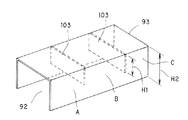
図6は、別の実施形態を示している。
【0046】
これによれば、上記支持部材93の内側に、その短手方向に延びて空気貯留部92を複数分割する仕切り体103が設けられている。
【0047】
この仕切り体103の高さH1は、支持部材93の高さH2よりも低く形成され、この支持部材93を氷蓄熱槽36内に設置する場合、この支持部材93が傾いて設置されたとしても、仕切り体103の高さH1によって、各室A〜Cに貯留される空気量が一定に維持される。
【0048】
従って、各室A〜Cにおいて、上記泡101の出方に極端な差が生じることがなく、ほぼ均一な抜気が可能になる。
【0049】
以上、本発明を上記実施の形態に基づいて説明したが、本発明はこれに限定されるものではない。例えば、上記実施の形態では、支持部材を下面が開口した箱形部材で構成したが、これに限定されず、本発明の趣旨を逸脱しない限り、種々の形態が適用されることは云うまでもない。
【0050】
【発明の効果】
本発明では、支持部材が、いわゆる空気供給用パイプとコイルを固定する支持部材とを兼ねるため、配管構造が簡素化され、コストダウンが図れると共に、氷蓄熱槽の組み立てが容易になる。
【図面の簡単な説明】
【図1】本発明に係る蓄熱ユニットを備えた空気調和装置の一実施の形態が適用された氷蓄熱ユニットを備えた空気調和装置を示し、製氷運転時の管路図である。
【図2】図1の一実施の形態における冷房運転時の管路図である。
【図3】氷蓄熱槽の断面図である。
【図4】氷蓄熱槽の断面斜視図である。
【図5】コイル周辺の氷を示す断面図である。
【図6】別の実施形態を示す支持部材の斜視図である。
【符号の説明】
10 空気調和装置
11 熱源側ユニット
12 氷蓄熱ユニット
13 利用側ユニット
21 熱源側熱交換器
24 利用側熱交換器
35 コイル
36 氷蓄熱槽
91 水柱
92 空気貯留部
93 支持部材
94 下部空間
95 パイプ(空気供給手段)
96 側壁
97 固定具
98 空気供給孔
111,111A 底部材[0001]
BACKGROUND OF THE INVENTION
The present invention relates to an air conditioner having an ice heat storage tank.
[0002]
[Prior art]
Generally, a heat source side unit having a compressor and a heat source side heat exchanger, an ice heat storage unit in which a coil is disposed in a submerged state in an ice heat storage tank, and a usage side unit having a usage side heat exchanger The air conditioning apparatus which it has is known (for example, refer patent document 1).
[0003]
In this type, the ice heat storage operation is performed by evaporating the refrigerant in the coil to produce ice, and the ice heat storage operation is performed by condensing the refrigerant in the coil and defrosting the ice around the coil. Do.
[0004]
By the way, conventionally, in order to promote heat transfer in the ice heat storage tank, an air supply pipe is provided at the bottom of the ice heat storage tank.
[0005]
During the operation using ice heat storage, air is guided through the pipe into an annular water column formed around the coil by the above ice melting, and an ascending water flow is formed in the water column to accelerate the ice melting speed.
[0006]
[Patent Document 1]
Japanese Patent Laid-Open No. 2000-46434
[Problems to be solved by the invention]
However, in the conventional configuration, in addition to providing the air supply pipe at the bottom of the ice heat storage tank, a support member for fixing the lower part of the coil is provided, which makes it difficult to assemble the ice heat storage tank. There's a problem.
[0008]
Accordingly, an object of the present invention is to solve the problems of the conventional techniques described above, enable air supply to the whole with a simple configuration, and promote air transfer in an ice heat storage tank. To provide an apparatus.
[0009]
[Means for Solving the Problems]
The invention according to claim 1 performs ice heat storage by evaporating the refrigerant in the coil and making ice, and uses ice heat storage by condensing the refrigerant in the coil and defrosting the ice around the coil. In the air conditioner including an ice heat storage tank, a plurality of bottom members are arranged side by side at the bottom of the ice heat storage tank, air supply means is provided on at least one bottom member, and the air supply means is provided on the bottom member. A support member having an air storage part for storing air supplied through is spanned, and an air supply hole is formed in the support member so as to be able to introduce air around the coil in communication with the air storage part. It is what.
[0010]
The invention according to
[0011]
According to a third aspect of the present invention, in the first or second aspect, the lower portion of the coil extends into the lower space of the support member.
[0012]
According to a fourth aspect of the present invention, in any one of the first to third aspects, the bottom member having the air supply means and the support member are each formed of a box-shaped member having an open bottom surface, and the coil is supported. It is fixed to the side wall of the member.
[0013]
According to a fifth aspect of the present invention, in the fourth aspect of the present invention, a partition that divides the air reservoir is provided inside the support member.
[0014]
DETAILED DESCRIPTION OF THE INVENTION
Hereinafter, embodiments of the present invention will be described with reference to the drawings.
[0015]
FIG. 1 shows an air conditioner equipped with an ice heat storage unit to which an embodiment of an air conditioner equipped with a heat storage unit according to the present invention is applied, and is a pipeline diagram during ice making operation. FIG. 2 is a pipeline diagram during the cooling operation in the embodiment of FIG.
[0016]
The
[0017]
In the heat source side unit 11,
[0018]
In the usage-
[0019]
The ice
[0020]
The ice
[0021]
[A] Ice making operation (Figure 1)
In the ice making operation of the
[0022]
In this case, in the ice
[0023]
Ice is formed in the ice
[0024]
[B] Ice-free cooling operation (Figure 2)
The ice-freezing and cooling operation of the
[0025]
In this case, in the ice
[0026]
In this state, when the
[0027]
Thereafter, the gas refrigerant passes through the
[0028]
Therefore, during this ice-freezing cooling operation, the cold heat stored in the ice in the ice
[0029]
Further, in the ice-freezing cooling operation described above, in the ice
[0030]
"C" normal cooling operation (Fig. 2)
The normal cooling operation in the
[0031]
In this state, when the
[0032]
“D” Structure of
[0033]
In the present embodiment, as shown in FIG. 4, a plurality of
[0034]
On these
[0035]
Each of the
[0036]
The
[0037]
In the present embodiment, during the ice making operation described above,
[0038]
Next, when the above-described ice melting operation is executed, as shown in FIG. 5, first, the ice around the
[0039]
In the present embodiment, the following effects (1) to (5) are obtained.
[0040]
(1) Since the
[0041]
(2) When air is supplied through the
[0042]
{Circle around (3)} Since the
[0043]
(4) Since the
[0044]
(5) Even if the size of the ice
[0045]
FIG. 6 shows another embodiment.
[0046]
According to this, the
[0047]
A height H1 of the
[0048]
Therefore, in each of the chambers A to C, there is no extreme difference in how the
[0049]
As mentioned above, although this invention was demonstrated based on the said embodiment, this invention is not limited to this. For example, in the above-described embodiment, the support member is configured by a box-shaped member having an open bottom surface. However, the present invention is not limited to this, and various forms can be applied without departing from the gist of the present invention. Absent.
[0050]
【The invention's effect】
In the present invention, since the support member serves as a so-called air supply pipe and a support member for fixing the coil, the piping structure is simplified, the cost can be reduced, and the ice heat storage tank can be easily assembled.
[Brief description of the drawings]
FIG. 1 is a pipe diagram showing an air conditioner equipped with an ice heat storage unit to which an embodiment of an air conditioner equipped with a heat storage unit according to the present invention is applied, during ice making operation.
FIG. 2 is a pipeline diagram during cooling operation in the embodiment of FIG. 1;
FIG. 3 is a cross-sectional view of an ice heat storage tank.
FIG. 4 is a cross-sectional perspective view of an ice heat storage tank.
FIG. 5 is a cross-sectional view showing ice around a coil.
FIG. 6 is a perspective view of a support member showing another embodiment.
[Explanation of symbols]
DESCRIPTION OF
96
Claims (5)
上記氷蓄熱槽の底部に複数の底部材を横並びに配置し、
少なくとも一つの底部材に空気供給手段を設け、
上記底部材の上に上記空気供給手段を通じて供給された空気を貯留する空気貯留部を有した支持部材を掛け渡し、
この支持部材に上記空気貯留部と連通してコイル周辺に空気を導入可能にした空気供給孔を形成したことを特徴とする空気調和装置。Air conditioning with an ice storage tank that performs ice heat storage by evaporating the refrigerant in the coil and making ice, and condensing the refrigerant in the coil to defrost the ice around the coil. In the device
A plurality of bottom members are arranged side by side at the bottom of the ice heat storage tank,
Air supply means is provided on at least one bottom member;
A support member having an air storage part for storing the air supplied through the air supply means is placed on the bottom member,
An air conditioner characterized in that an air supply hole is formed in the support member so as to be able to introduce air around the coil in communication with the air storage section.
上記コイル内で冷媒を蒸発させて製氷することにより氷蓄熱を行うと共に、上記コイル内で冷媒を凝縮させてコイル周辺の氷を解氷させることにより氷蓄熱利用を行う空気調和装置において、
上記氷蓄熱槽の底部に複数の底部材を横並びに配置し、
少なくとも一つの底部材に空気供給手段を設け、
上記底部材の上に上記空気供給手段を通じて供給された空気を貯留する空気貯留部を有した支持部材を掛け渡し、
この支持部材に上記空気貯留部と連通してコイル周辺に空気を導入可能にした空気供給孔を形成したことを特徴とする空気調和装置。A heat source side unit including a compressor and a heat source side heat exchanger, an ice heat storage unit in which a coil is disposed in a submerged state in an ice heat storage tank, and a utilization side unit including a utilization side heat exchanger ,
In the air conditioner that performs ice heat storage by evaporating the refrigerant in the coil and making ice, and condensing the refrigerant in the coil and defrosting the ice around the coil to use ice heat storage,
A plurality of bottom members are arranged side by side at the bottom of the ice heat storage tank,
Air supply means is provided on at least one bottom member;
A support member having an air storage part for storing the air supplied through the air supply means is placed on the bottom member,
An air conditioner characterized in that an air supply hole is formed in the support member so as to be able to introduce air around the coil in communication with the air storage section.
Priority Applications (1)
| Application Number | Priority Date | Filing Date | Title |
|---|---|---|---|
| JP2002292300A JP3790207B2 (en) | 2002-10-04 | 2002-10-04 | Air conditioner |
Applications Claiming Priority (1)
| Application Number | Priority Date | Filing Date | Title |
|---|---|---|---|
| JP2002292300A JP3790207B2 (en) | 2002-10-04 | 2002-10-04 | Air conditioner |
Publications (2)
| Publication Number | Publication Date |
|---|---|
| JP2004125323A JP2004125323A (en) | 2004-04-22 |
| JP3790207B2 true JP3790207B2 (en) | 2006-06-28 |
Family
ID=32283598
Family Applications (1)
| Application Number | Title | Priority Date | Filing Date |
|---|---|---|---|
| JP2002292300A Expired - Lifetime JP3790207B2 (en) | 2002-10-04 | 2002-10-04 | Air conditioner |
Country Status (1)
| Country | Link |
|---|---|
| JP (1) | JP3790207B2 (en) |
Families Citing this family (1)
| Publication number | Priority date | Publication date | Assignee | Title |
|---|---|---|---|---|
| JP5871161B2 (en) * | 2012-01-30 | 2016-03-01 | 三浦工業株式会社 | Ice heat storage device |
-
2002
- 2002-10-04 JP JP2002292300A patent/JP3790207B2/en not_active Expired - Lifetime
Also Published As
| Publication number | Publication date |
|---|---|
| JP2004125323A (en) | 2004-04-22 |
Similar Documents
| Publication | Publication Date | Title |
|---|---|---|
| JP5327308B2 (en) | Hot water supply air conditioning system | |
| JP5920178B2 (en) | Heat pump cycle | |
| JP6575690B2 (en) | Equipment temperature controller | |
| KR20180093055A (en) | Heat exchanger with water chamber | |
| JP2013083439A5 (en) | ||
| JP2013083439A (en) | Hot water supply air conditioning system | |
| KR101756213B1 (en) | Cold reserving heat exchanger | |
| WO2010001643A1 (en) | Cooling device and method for manufacturing the same | |
| JP4609316B2 (en) | refrigerator | |
| CN106403095B (en) | Heat generating unit | |
| JP3790207B2 (en) | Air conditioner | |
| KR101551692B1 (en) | Cold reserving heat exchanger | |
| JP3814570B2 (en) | Air conditioner | |
| JP2005106339A (en) | Heat exchanger and heat pump type air conditioner using the same | |
| JP2003240386A (en) | Heat-exchanger with receiver tank, coupling member for receiver tank, fitting structure for heat-exchanger to receiver tank, and refrigerating system | |
| KR101418155B1 (en) | An air conditioner | |
| JP2006038290A (en) | Air conditioner | |
| KR20110100002A (en) | With pcm(phase change material) dual evaporator | |
| JP2010145041A (en) | Air conditioning system | |
| JP3920540B2 (en) | Air conditioner | |
| JP3802237B2 (en) | Air conditioner with ice storage tank | |
| JP3831529B2 (en) | Ice heat storage unit of air conditioner | |
| JP3643687B2 (en) | Air conditioner with ice heat storage unit | |
| JP4046477B2 (en) | Air conditioner | |
| JP2016142483A (en) | Air cooler |
Legal Events
| Date | Code | Title | Description |
|---|---|---|---|
| A621 | Written request for application examination |
Free format text: JAPANESE INTERMEDIATE CODE: A621 Effective date: 20050720 |
|
| TRDD | Decision of grant or rejection written | ||
| A01 | Written decision to grant a patent or to grant a registration (utility model) |
Free format text: JAPANESE INTERMEDIATE CODE: A01 Effective date: 20060314 |
|
| A61 | First payment of annual fees (during grant procedure) |
Free format text: JAPANESE INTERMEDIATE CODE: A61 Effective date: 20060330 |
|
| R150 | Certificate of patent or registration of utility model |
Free format text: JAPANESE INTERMEDIATE CODE: R150 Ref document number: 3790207 Country of ref document: JP Free format text: JAPANESE INTERMEDIATE CODE: R150 |
|
| FPAY | Renewal fee payment (event date is renewal date of database) |
Free format text: PAYMENT UNTIL: 20090407 Year of fee payment: 3 |
|
| FPAY | Renewal fee payment (event date is renewal date of database) |
Free format text: PAYMENT UNTIL: 20100407 Year of fee payment: 4 |
|
| R250 | Receipt of annual fees |
Free format text: JAPANESE INTERMEDIATE CODE: R250 |
|
| FPAY | Renewal fee payment (event date is renewal date of database) |
Free format text: PAYMENT UNTIL: 20110407 Year of fee payment: 5 |
|
| R250 | Receipt of annual fees |
Free format text: JAPANESE INTERMEDIATE CODE: R250 |
|
| R250 | Receipt of annual fees |
Free format text: JAPANESE INTERMEDIATE CODE: R250 |
|
| FPAY | Renewal fee payment (event date is renewal date of database) |
Free format text: PAYMENT UNTIL: 20120407 Year of fee payment: 6 |
|
| FPAY | Renewal fee payment (event date is renewal date of database) |
Free format text: PAYMENT UNTIL: 20130407 Year of fee payment: 7 |
|
| R250 | Receipt of annual fees |
Free format text: JAPANESE INTERMEDIATE CODE: R250 |
|
| FPAY | Renewal fee payment (event date is renewal date of database) |
Free format text: PAYMENT UNTIL: 20130407 Year of fee payment: 7 |
|
| FPAY | Renewal fee payment (event date is renewal date of database) |
Free format text: PAYMENT UNTIL: 20140407 Year of fee payment: 8 |
|
| R250 | Receipt of annual fees |
Free format text: JAPANESE INTERMEDIATE CODE: R250 |
|
| R250 | Receipt of annual fees |
Free format text: JAPANESE INTERMEDIATE CODE: R250 |
|
| R250 | Receipt of annual fees |
Free format text: JAPANESE INTERMEDIATE CODE: R250 |
|
| R250 | Receipt of annual fees |
Free format text: JAPANESE INTERMEDIATE CODE: R250 |
|
| R250 | Receipt of annual fees |
Free format text: JAPANESE INTERMEDIATE CODE: R250 |
|
| R250 | Receipt of annual fees |
Free format text: JAPANESE INTERMEDIATE CODE: R250 |
|
| R250 | Receipt of annual fees |
Free format text: JAPANESE INTERMEDIATE CODE: R250 |
|
| R250 | Receipt of annual fees |
Free format text: JAPANESE INTERMEDIATE CODE: R250 |
|
| R250 | Receipt of annual fees |
Free format text: JAPANESE INTERMEDIATE CODE: R250 |
|
| R250 | Receipt of annual fees |
Free format text: JAPANESE INTERMEDIATE CODE: R250 |
|
| EXPY | Cancellation because of completion of term |