JP3782026B2 - Impedance parameter estimation method and apparatus - Google Patents
Impedance parameter estimation method and apparatus Download PDFInfo
- Publication number
- JP3782026B2 JP3782026B2 JP2002063205A JP2002063205A JP3782026B2 JP 3782026 B2 JP3782026 B2 JP 3782026B2 JP 2002063205 A JP2002063205 A JP 2002063205A JP 2002063205 A JP2002063205 A JP 2002063205A JP 3782026 B2 JP3782026 B2 JP 3782026B2
- Authority
- JP
- Japan
- Prior art keywords
- current
- impedance
- voltage
- test impedance
- test
- Prior art date
- Legal status (The legal status is an assumption and is not a legal conclusion. Google has not performed a legal analysis and makes no representation as to the accuracy of the status listed.)
- Expired - Lifetime
Links
Images


Description
【0001】
【産業上の利用分野】
本発明は、等価回路で表わされた供試インピーダンスのパラメータ値を推定するインピーダンスパラメータの推定方法及び装置に関するものである。
【0002】
【従来の技術】
従来、電池などの起電力を含む測定対象物や、あるいは起電力を含まない測定対象物の内部インピーダンスを測る場合、その内部インピーダンスを等価回路で表現し、その各パラメータを次のような方法で推定していた。
【0003】
(A)電流遮断法:
図7は電流遮断法によるインピーダンスパラメータ推定回路例である。供試インピーダンスは、図8に示すような起電力V1を含む等価回路で表わされ、例えば、溶液抵抗Rs、反応抵抗r1及び二重層容量Cdから成り、等価回路中のパラメータRsのみを測定できる。
【0004】
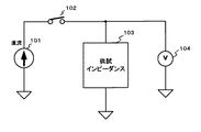
図7において、直流電流源101からの電流は、スイッチ102を経由して供試インピーダンス103に供給され、この供試インピーダンス103の両端電圧が電圧測定部104で測定される。
【0005】
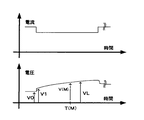
測定時には、先ず、スイッチ102をオン状態として供試インピーダンス103に電流Imを流しておく。次に、キャパシタCdと抵抗r1による時定数の影響が無視できる程度の短時間だけスイッチ102をオフとし、その後、再びオンとする。このとき得られる供試インピーダンス103に流れる電流と両端の電圧の時間関係が図9に示されている。電流を遮断した前後における供試インピーダンス103の両端の電圧V0、V1を電圧測定部104で測定し、得られた値を用いて供試インピーダンスのパラメータRsを推定する。
【0006】
(B)交流法:
図10は交流法による供試インピーダンス推定回路例である。供試インピーダンス205には、直流電流源201及び交流信号源204の交流電流が供給される。交流信号源204は、抵抗203と交流電流計202を介して供試インピーダンス205に接続されている。
【0007】
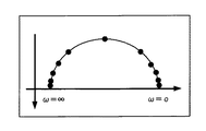
測定に際しては、供試インピーダンス205に印加する交流の周波数を広い範囲に渡って変化させ、各周波数における供試インピーダンス205の両端電圧を交流電圧計206で測定し、その値と交流電流計202の測定値との比である複素インピーダンスを算出する。次に、この供試インピーダンスの複素インピーダンスを図11に示すように複素平面にプロットして複素平面インピーダンス図(コールコール・プロット等)を作成し、このグラフから供試インピーダンス205のパラメータRs、r1、Cdを推定している。
【0008】
【発明が解決しようとする課題】
しかしながら、上記に示す従来のインピーダンスパラメータの推定方法では次のような問題点があった。
【0009】
上述(A)の電流遮断法では、図8に示す等価回路中のパラメータRsは推定できるものの、r1やCdは推定できない。供試インピーダンス中に起電力を含まない場合であれば、電流遮断の時間を増せば測定した電圧からr1も求まる。しかし、通常、供試インピーダンスは通電電流の大きさによってパラメータ値が変化することを考慮すると、電流遮断法では電流を大きく変化させるので、どの電流値のインピーダンスパラメータ値であるかが一意に定まらない。
【0010】
また、電流遮断を行う際、スイッチ102の性能上の制約から図9の電圧波形の変化直後に過渡現象が生じるため、それが整定するまでの間はV1測定に支障が出る場合がある。
【0011】
更に、(B)の交流法では、図8の等価回路のパラメータRs、r1、Cdをすべて推定できる。また、供試インピーダンスが非線形性を有し通電電流によってそのパラメータが変化する場合でも通電電流、すなわち直流電流源201の出力電流値は一意に確定できる。
【0012】
しかし、一般的にコールコール・プロットを得るためには多数の周波数について測定を行わなければならないため、測定に時間がかかるという問題がある。
【0013】
更に、得られたコールコール・プロットに対して等価回路を表す半円を手動で当てはめ、その半径とX軸上の中心座標の値からパラメータを推定しているが、このようにパラメータ推定において手動部分が多いため自動化が困難である。
【0014】
そこで、本発明の目的は、通電電流に対する供試インピーダンスの等価回路パラメータを高精度且つ迅速に求めることができるインピーダンスパラメータの推定方法及び装置を提供することにある。
【0015】
【課題を解決するための手段】
前述の課題を解決するため、本発明によるインピーダンスパラメータの推定方法及び装置は、次のような特徴的な構成を採用している。
【0016】
(1) 供試インピーダンスに流れる通電電流がその基準値である直流電流に矩形波電流の加算により矩形波状の変化を有し、前記通電電流により前記供試インピーダンスから得られる電圧データを時系列的に求め、これら電圧データから前記供試インピーダンスの等価回路を構成するパラメータを推定することを特徴とするインピーダンスパラメータの推定方法。
(2) 供試インピーダンスに流れる通電電流がその基準値である直流電流に矩形波電流の加算により矩形波状の変化を有し、前記通電電流を以て前記供試インピーダンスから得られる電圧データを時系列的に求め、得られた複数の電圧データの平均値を求め、この平均値から前記供試インピーダンスの等価回路を構成するパラメータを推定することを特徴とするインピーダンスパラメータの推定方法。
(3) 供試インピーダンスに流れる通電電流がその基準値である直流電流に矩形波電流の加算により矩形波状の変化を有し、前記通電電流を以て前記供試インピーダンスから得られる電圧データを時系列的に求め、これら電圧データから前記供試インピーダンスの等価回路を構成する複数のパラメータを推定し、この推定により得られた複数のパラメータの平均値を求め、この平均値から前記供試インピーダンスの等価回路を構成するパラメータを推定することを特徴とするインピーダンスパラメータの推定方法。
(4) 供試インピーダンスに流れる通電電流がその基準値である直流電流に矩形波電流の加算により矩形波状の変化を有し、前記通電電流により前記供試インピーダンスから得られる電圧データを時系列的に求め、
これら電圧データから推定される、前記供試インピーダンスの等価回路を構成するパラメータを求め、該パラメータを初期値とし、この初期値を前記等価回路を構成するパラメータに用いて前記供試インピーダンスの両端電圧を算出し、
この両端電圧と、前記供試インピーダンスから実際に時系列的に測定された両端電圧の電圧データとの誤差を算出し、
この誤差が最小となるときの前記等価回路を構成するパラメータを推定することを特徴とするインピーダンスパラメータの推定方法。
(5) 供試インピーダンスに流れる通電電流がその基準値である直流電流に矩形波電流の加算により矩形波状の変化を有し、前記通電電流を以て前記供試インピーダンスから得られる電圧データを時系列的に求め、これら電圧データの平均値を求め、この平均値から前記供試インピーダンスの等価回路を構成するパラメータを推定し、この推定により得られたパラメータを初期値とし、この初期値を前記供試インピーダンスの等価回路を構成するパラメータに用いて前記供試インピーダンスの両端電圧を算出し、
この両端電圧と、前記供試インピーダンスから実際に時系列的に測定された両端電圧の電圧データとの誤差を算出し、
この誤差が最小となるときの前記供試インピーダンスの等価回路を構成するパラメータを推定することを特徴とするインピーダンスパラメータの推定方法。
(6) 供試インピーダンスの等価回路を構成するパラメータを推定するインピーダンスパラメータの推定装置であって、
基準値である直流電流に矩形波電流の加算により予め定めた時間だけ変化させた通電電流を前記供試インピーダンスに供給する電流供給手段と、
前記通電電流に前記変化を与える直前の時刻、前記通電電流を変化させる前記時間内の少なくとも2点の時刻で、前記供試インピーダンスの両端電圧を測定する電圧測定手段と、
を備え、前記電圧測定手段で得られた電圧データから前記供試インピーダンスの等価回路を構成するパラメータを推定することを特徴とするインピーダンスパラメータの推定装置。
(7) 供試インピーダンスの等価回路を構成するパラメータを推定するインピーダンスパラメータの推定装置であって、
基準値である直流電流に矩形波電流の加算により予め定めた時間だけ変化させた通電電 流を前記供試インピーダンスに供給する電流供給手段と、
前記通電電流に前記変化を与える直前の時刻、前記通電電流に変化が与えられる前記時間内の少なくとも2点の時刻の各時刻で前記供試インピーダンスの両端電圧を測定する電圧測定手段と、
前記電圧測定手段により前記各時刻で得た電圧データを用いて算出された前記パラメータを初期値とし、この初期値を前記供試インピーダンスの等価回路を構成するパラメータに用いて前記供試インピーダンスの両端電圧を算出し、この両端電圧と前記電圧測定手段により得た前記電圧データとの誤差を最小とするカーブフィット手段と、
を備えることを特徴とするインピーダンスパラメータの推定装置。
【0020】
【発明の実施の形態】
以下、本発明によるインピーダンスパラメータの推定方法及び装置の好適実施形態を添付図を参照しながら説明する。
【0021】
<第1の実施形態>
図1は本発明の一実施形態による供試インピーダンスのパラメータ推定回路図である。
【0022】
本実施形態による供試インピーダンスのパラメータ推定方法及び装置の概略を述べると次のようになる。すなわち、供試インピーダンスをどのくらいの電流で測定するかを決める通電電流を流すと同時に、これに比べて振幅のはるかに小さい矩形状電流を与え、このときの供試インピーダンス両端の電圧を時系列的に採取し、この採取データから供試インピーダンスの等価回路中のパラメータRs、r1、Cdの各初期値を算出する。測定データの採取はこの1回のみで良い。
【0023】
次に、これら初期値を供試インピーダンスの等価回路パラメータに代入して供試インピーダンス両端の電圧を計算により求める。続いて、この計算値と、実際に測定した前記時系列電圧データとの二乗誤差を求める。
【0024】
そして、周知の最急降法(「アルゴリズム辞典」1994年、共立出版、pp.270参照)により前記二乗誤差関数が最小となるまで上記操作を繰り返す。
【0025】
図1において、供試インピーダンス3には、第1の直流電流源1からその測定ポイントを決める通電電流が供給され、更にこの通電電流に加算する形で第2の直流電流源5がスイッチ2を介して予め定めた時間(供試インピーダンスの値にもよるが、例えば0.1秒)だけ供給される。この第2の直流電流源5の電流値Imは、第1の電流源1による通電電流に比較して数%程度の十分小さい値である。これはImの値があまり大きいと測定時の通電電流の値が一意的に定まらないからである。
【0026】
測定に際しては、直流電流源1によって測定ポイントの通電電流を設定した後、スイッチ2を短い時間だけオフし、その時点を挟んだ前後の供試インピーダンス両端の時系列電圧データを採取する。尚、スイッチ2をオフした直後の時系列電圧データのいくつかはスイッチ2の性能上の制約から生じる測定回路の過渡応答の影響を避けるため用いない。
【0027】
供試インピーダンス3の両端電圧は電圧測定部4により測定され、時系列的電圧データとして収集してデジタルデータ化している。そして電圧測定部4で得られた時系列電圧データはカーブフィット部6に送出される。カーブフィット部6では、前記電圧測定部4による時系列電圧データと予め与えられた等価回路モデルとから、以下に述べるカーブフィット処理により供試インピーダンスの等価回路パラメータRs、r1、Cdを推定する。カーブフィット部6で得られた各パラメータ値は表示部7で表示される。
【0028】
上記カーブフィット処理は以下の処理(1)〜(7)の手順に従って実行される。
【0029】
(1)図2に示す、第2の直流電流源5とスイッチ2による矩形状電流を加算する直前の電圧V0、直後の電圧V1、測定用電流値Imから等価パラメータRsの初期値Rsiを次式で算出する。ここで電圧V1採取においては、矩形状電流の加算直後の過渡現象を避けることは前述した通りである。
Rsi =(V1−V0)/Im
【0030】
(2)次に、矩形状電流の加算後、加算終了前の電圧VLから等価パラメータr1の初期値r1iを次式で算出する。ここで、VLの採取タイミングであるが、矩形状電流の終了間際まで待つ必要はない。図2に示すように、矩形状電流の印加時間の途中で十分である。これは初期値算出の過程は、あくまでも以後の計算の「タネ」となる数値を決定するだけなので厳密さは要求されないからである。
r1i ={( VL−V0 )/Im }−Rsi
【0031】
(3)測定した時系列電圧データ内の中程の時刻T(M)と、そのときの電圧V(M)から等価回路パラメータCdの初期値を次式で算出する。
すなわち、図8の等価回路において、時刻T(M)のときの両端電圧をV(M)、流れる電流をImとすると次式を得る。
V(M)=Im・Rsi+Im・r1i{1-exp(-T(M)/(Cdi・r1i))}
【0032】
したがって、Cdi は次式で得られる。
Cdi =−T(M)/[r1i・log{1−((V(M)/Im)−Rsi)/r1i}]
尚、図2ではV(M)<VLであるが、これは逆であっても良い。
【0033】
(4)各パラメータの初期値Rsi、r1i、Cdiを図8に示す等価回路に適用した場合、供試インピーダンス両端のモデル応答の電圧f(Rs,r1,Cd)は(3)のV(M)の式と同等であるので、次のようになる。
f(Rs,r1,Cd)=[Rs +r1{1-exp(-T(M)/(Cd・r1))} ]・Im
ここで、モデル応答f(Rs,r1,Cd)と実測値V(M)との差を取り、これを次式に示す誤差関数erf( Rs,r1,Cd )とする。
【数1】

【数2】
(5)上記で求めた等価パラメータの初期値Rsi、r1i、Cdiから始めて、この二乗誤差関数erf ( Rs,r1、Cd )が最小値を示すまで以下の(6)、(7)の処理を繰り返す。
【0035】
(6)この二乗誤差関数式を各変数Rs、r1、Cdについて偏微分し、これら変数から成る一次結合(C1・Rs+C2・r1+C3・Cd:ここでC1〜C3は係数)を調べて最も傾きが急な方向を求める。
【0036】
(7)上記処理(6)で決定された方向に変数Rs、r1、Cdの値を変化させ、その方向で、二乗誤差が最少となる点を求め、再び処理(6)を行う。
【0037】
上記の二乗誤差関数erf(Rs,r1,Cd)が最小値を示したときのRs、r1、Cdが求める供試インピーダンスの各パラメータの推定値である。
【0038】
図2に示す、時系列電圧データの採取期間であるが、これはスイッチ2をオフしている期間中のすべてのデータを採取する必要はなく、図2に示すように矩形状電流の途中までのデータ採取で良い。
【0039】
本発明では、1回のデータ収集(スイッチ2による矩形状電流加算は1回)だけで供試インピーダンスのパラメータを推定できる。
【0040】
尚、本実施形態では、第2の直流電流源5をスイッチ2を介して加算しているが、第1の直流電流源のみを用い、通電電流を与えるとともに矩形状の電流変化を与えても同様の効果が得られることは勿論である。
【0041】
<第2の実施形態>
図3は第2の実施形態に使用する直流電流源5と2極双投スイッチ8であり、他の部分は図1の第1の実施形態と同じである。
【0042】
第2の実施形態では直流電流源5が2極双投のスイッチ8に接続されており、2極双投スイッチ8をa側、b側に交互に切り換えることより矩形状電流の極性を正負交互に供試インピーダンス3に加算することができる。その様子を図4に示す。
【0043】
測定の手順等は第1の実施形態と同様であり、矩形状電流を交互に印加して、このときの供試インピーダンス両端の時系列データを採取する。そしてこのデータを用いて各矩形状電流印加時のパラメータ推定を行い、これらを平均化して最終的に供試インピーダンスのパラメータを推定する。
【0044】
このように正負交互に測定用電流を加算することにより通電電流の平均値を変化させること無く測定が行える。したがって、この技術を複数回のデータ収集に適用すれば、測定のS/N向上はもちろんのこと、通電電流の平均値を変化させることなく測定を行えるため、測定条件をより厳密に定めることができるというメリットがある。
【0045】
ここで、第2の実施形態において、第2の直流電流源5及び2極双投スイッチ8を用いずに、第1の直流電流源の電流値を通電電流である基準値に対して増減しても同じ効果が得られることは勿論である。
【0046】
図5は第3の実施形態を示す図であり、供試インピーダンス3に対して図2又図4に示す測定パルスを繰り返し印加して測定データの平均化を行うように構成されている。こうすることにより、より確度の高いインピーダンスパラメータの推定を可能とした例である。供試インピーダンス3の両端電圧を電圧測定部4で複数回採取し、これらのデータを平均化して測定時のSN比を向上させる。
【0047】
図5のブロック図を参照しながら本実施形態を説明する。供試インピーダンス3の両端電圧は、A/D変換回路501でデジタル信号に変換される。このデジタル信号は、加算回路502及び波形メモリ503から成る累積回路に加えられる。加算回路には2つの入力端子があり、一方にはA/D変換回路501からのデータが入力され、他方には波形メモリの出力データが入力されている。スケーリング回路504は、累積回数に対応して、波形メモリ503の出力データをスケーリングする。制御回路505は、A/D変換回路501のサンプリング・スタートや波形メモリのタイミングを決める。
【0048】
具体的な動作を説明すると、先ず測定を開始するとき、すなわち初期状態では波形メモリはクリアされている。この状態で供試インピーダンス3に図2又は図4に示す電流変化を与えて1回目の測定を行い、A/D変換回路501からデータdata1が出力される。すると、このデータdata1は、加算回路502の一方の入力に供給され、他方の入力には波形メモリ503の出力が供給されている。この波形メモリは、前述の通り、初期状態ではクリアされているので、この入力値はゼロである。従って、加算回路502の出力はデータdata1となり、これが波形メモリに蓄積される。
【0049】
2回目の測定において、A/D変換回路501からデータdata2が出力されたとする。すると、加算回路には、このデータdata2及び波形メモリ503からの出力(data1)とが入力されるので、加算回路502の出力はデータ(data1+data2)となる。
【0050】
以下、3回目の測定ではデータdata3が、4回目の測定ではデータdata4が、というように順次N回のデータ採取を行うと、波形メモリにはデータ(data1+data2+・・・+data N)が蓄積される。この積算結果は、スケーリング回路504に入力され、その出力からは1/Nにスケールダウンされたデータ(data1+data2+・・・+data N)/N、即ち平均値が出力される。そして、この測定データの平均値を用いて第1の実施例と同様に、供試インピーダンス3のパラメータ値を推定する。
【0051】
以上述べたように平均化を行えば、測定値の分散、即ちバラツキは測定回数をNとすると1/√Nに減少する。これは例えば、測定回数Nを16とするとそのバラツキは1/4になることを意味する。この結果、測定の信頼度が大幅に向上し、供試インピーダンス3のパラメータ推定の確度も向上する。
【0052】
本発明は第1の実施形態でも述べたように、平均化を行わない場合、わずか1回の測定(電流変化)を行うだけでインピーダンスパラメータ推定が行えるという本質的に高速な測定方法である。このため、平均化のために測定回数が増加したとしても、トータルな測定時間は従来の交流法など対しても十分な優位性を持っている。
【0053】
また、本実施例では測定データの平均化を行い、その後にパラメータの推定を行う場合について述べたが、これとは違い、測定データを1回採取する毎にパラメータを推定し、これらの推定パラメータ値を平均化しても良い。
【0054】
尚、本発明は、上述実施形態に限定されず種々の変形が可能である。例えば、上記実施形態では等価回路モデルとして図8の回路を用いたが、異なる回路構成、すなわち抵抗と容量の並列部分が複数存在する場合等でも本発明は適用可能である。また、図8の等価回路において、起電力V1を含まない場合でも本発明は適用可能である。
【0055】
また、上記実施形態では、カーブフィットの手法として各測定点の推定等価回路の応答からの誤差の二乗和を最小とする手法を用いたが、他の評価関数によるカーブフィットを用いることもできる。また、等価回路モデルに合わせて、その他任意の数学的回帰分析手法を用いることもできる。
【0056】
更に、上記実施形態ではカーブフィット手法を用いて等価回路パラメータRs、r1、Cdの値を推定している。しかし、Rsのみを求めたい場合は、図6に示すように印加する矩形状電流の幅をCdとr1による時定数の影響が無視できる程度の短時間とし、実施形態1に示すカーブフィット処理(1)のみを行う。こうすることにより、測定時間を電流遮断法と同程度に短縮しながら、測定時の電流変化を極めて少なくできるため、通電電流を一意に定めることができる。
【0057】
【発明の効果】
以上述べたように、本発明は、通電電流及びそれに重畳した矩形状電流を供給したときの供試インピーダンスの端子に発生する時系列電圧データを採取し、この採取データを用いてカーブフィット処理を行うことにより供試インピーダンスの等価回路パラメータを推定している。本発明によれば、供試インピーダンス中に起電力を有していても任意のパラメータを少なくとも1回の矩形状の電流変化で推定することができるという優れた特長を持っている。
【0058】
また本発明によれば、測定に際しての矩形状の電流変化は微少であるため、供試インピーダンスが非線形の場合であっても直流通電電流を一意に定めることが可能である。したがって、パラメータ推定の測定条件の明確化が図れるという従来技術には無い優れた効果を持っている。
【0059】
更に、通電電流に対して矩形状電流を正負交互に加算、すなわち通電電流に対して矩形状に電流を増減することにより、通電電流の平均値に影響を与えること無く測定が行えるという極めて優れた特長を持っている。
【図面の簡単な説明】
【図1】本発明の一実施形態による供試インピーダンスのパラメータ推定回路図である。
【図2】第1の実施形態における矩形状電流を加算する前後の電流と電圧の変化を示す図である。
【図3】本発明の第2の実施形態に使用する電流源と2極双投スイッチを示す図である。
【図4】図3に示す本発明の第2の実施形態による測定結果としての電流と電圧の変化を示す図である。
【図5】本発明の第3の実施形態による供試インピーダンスのパラメータ推定回路図である。
【図6】本発明において、Rsのみを求める場合の測定結果である。
【図7】従来の電流遮断法によるインピーダンスパラメータ推定回路例を示す図である。
【図8】供試インピーダンスの等価回路である。
【図9】電流遮断法における供試インピーダンスの両端電圧波形とそこに流れる電流の時間波形図である。
【図10】交流法による供試インピーダンス推定回路例を示す図である。
【図11】図9に示す供試インピーダンス推定回路で作成する複素平面インピーダンス図である。
【符号の説明】
1 第1の直流電流源
2 スイッチ
3 供試インピーダンス
4 電圧測定部
5 第2の直流電流源
6 カーブフィット部
7 表示部
8 2極双投スイッチ
101 直流電流源
102 スイッチ
103 供試インピーダンス
104 電圧測定部
201 直流電流源
202 交流電流計
203 抵抗
204 交流信号源
205 供試インピーダンス
206 交流電圧計
501 A/D変換回路
502 加算回路
503 波形メモリ
504 スケーリング回路
505 制御回路[0001]
[Industrial application fields]
The present invention relates to an impedance parameter estimation method and apparatus for estimating a parameter value of a test impedance represented by an equivalent circuit.
[0002]
[Prior art]
Conventionally, when measuring the internal impedance of a measurement object that includes an electromotive force such as a battery or a measurement object that does not include an electromotive force, the internal impedance is expressed by an equivalent circuit, and each parameter is expressed by the following method. I was estimating.
[0003]
(A) Current interruption method:
FIG. 7 shows an example of an impedance parameter estimation circuit based on the current interruption method. The test impedance is represented by an equivalent circuit including an electromotive force V 1 as shown in FIG. 8, and is composed of, for example, a solution resistance R s , a reaction resistance r 1, and a double layer capacitance C d , and a parameter R in the equivalent circuit. Only s can be measured.
[0004]
In FIG. 7, the current from the DC current source 101 is supplied to the
[0005]
At the time of measurement, first, the
[0006]
(B) Exchange method:
FIG. 10 shows an example of a test impedance estimation circuit by the AC method. The
[0007]
In measurement, the AC frequency applied to the
[0008]
[Problems to be solved by the invention]
However, the conventional impedance parameter estimation methods described above have the following problems.
[0009]
In the current cutoff method of (A) described above, although the parameter R s in the equivalent circuit shown in FIG. 8 can be estimated, r 1 and C d cannot be estimated. If no electromotive force is included in the test impedance, r 1 can also be obtained from the measured voltage by increasing the current interruption time. However, considering that the parameter value of the test impedance usually changes depending on the magnitude of the energization current, the current interruption method changes the current greatly, so it is not possible to uniquely determine the current impedance parameter value. .
[0010]
Also, when performing the current interruption, because the transient phenomenon occurs from constraints on the performance of the
[0011]
Furthermore, in the AC method of (B), all of the parameters R s , r 1 , and C d of the equivalent circuit in FIG. 8 can be estimated. Further, even when the test impedance has nonlinearity and the parameter varies depending on the energization current, the energization current, that is, the output current value of the DC
[0012]
However, in general, in order to obtain a Cole-Cole plot, it is necessary to perform measurement for a large number of frequencies.
[0013]
Furthermore, a semicircle representing an equivalent circuit is manually applied to the obtained Cole-Cole plot, and the parameters are estimated from the radius and the value of the central coordinate on the X axis. It is difficult to automate because there are many parts.
[0014]
Accordingly, an object of the present invention is to provide an impedance parameter estimation method and apparatus capable of quickly and accurately obtaining an equivalent circuit parameter of a test impedance with respect to an energized current.
[0015]
[Means for Solving the Problems]
In order to solve the above-described problem, the impedance parameter estimation method and apparatus according to the present invention employ the following characteristic configuration.
[0016]
(1) The energized current flowing through the test impedance has a rectangular wave shape change by adding the rectangular wave current to the DC current which is the reference value, and voltage data obtained from the test impedance by the energized current is time-series. And estimating the parameters that constitute the equivalent circuit of the test impedance from these voltage data.
(2) The energizing current flowing through the test impedance has a rectangular wave change by adding the rectangular wave current to the DC current which is the reference value, and the voltage data obtained from the test impedance using the energizing current is time-series. estimation method determined, an average value of the plurality of voltage data obtained, the impedance parameter, wherein the benzalkonium to estimate the parameters constituting the equivalent circuit of the test impedance from the mean value.
(3) The energizing current flowing through the test impedance has a rectangular wave shape change by adding the rectangular wave current to the DC current which is the reference value, and the voltage data obtained from the test impedance using the energizing current is time-series. A plurality of parameters constituting an equivalent circuit of the test impedance from these voltage data, an average value of the plurality of parameters obtained by the estimation is obtained, and an equivalent circuit of the test impedance is obtained from the average value An estimation method of an impedance parameter, characterized by estimating a parameter constituting the parameter.
(4) The energizing current flowing through the test impedance has a rectangular wave shape change by adding the rectangular wave current to the DC current which is the reference value, and voltage data obtained from the test impedance by the energizing current is time-series. Seeking
A parameter constituting the equivalent circuit of the test impedance estimated from these voltage data is obtained, and the initial value of the parameter is used as a parameter constituting the equivalent circuit. To calculate
Calculate the error between the voltage across this terminal and the voltage data of the voltage across the terminal actually measured in time series from the test impedance,
Estimation method of impedance parameters and estimates the parameters that the error constituting the front SL equivalence circuit when the minimum.
(5) The energizing current flowing through the test impedance has a rectangular wave shape change by adding the rectangular wave current to the DC current that is the reference value, and the voltage data obtained from the test impedance using the energizing current is time-series. Then, an average value of these voltage data is obtained, a parameter constituting the equivalent circuit of the test impedance is estimated from the average value, and the parameter obtained by the estimation is set as an initial value, and the initial value is used as the test value. Calculate the voltage across the test impedance using the parameters that make up the equivalent circuit of the impedance,
Calculate the error between the voltage across this terminal and the voltage data of the voltage across the terminal actually measured in time series from the test impedance,
A method for estimating an impedance parameter, comprising estimating a parameter constituting an equivalent circuit of the test impedance when the error is minimized .
(6) The apparatus for estimating impedance parameters for estimating the parameters constituting the equivalent circuit of the test trial impedance,
A current supply means for supplying an energized current, which is changed for a predetermined time by adding a rectangular wave current to a direct current that is a reference value, to the test impedance ;
Voltage measuring means for measuring a voltage across the test impedance at a time immediately before giving the change to the energizing current, at least two points in the time for changing the energizing current ;
The provided, estimator impedance parameters and estimates the parameters that constitute the equivalent circuit of the test impedance from the voltage data obtained by the voltage measuring means.
(7) The apparatus for estimating impedance parameters for estimating the parameters constituting the equivalent circuit of the test trial impedance,
A current supply means for supplying a predetermined time by energizing current is varied in the test impedance by addition of the square wave current into a direct current which is the reference value,
Voltage measuring means for measuring the voltage across the test impedance at each of the time immediately before applying the change to the energized current and at least two times within the time when the change is applied to the energized current ;
The parameter calculated using the voltage data obtained at each time by the voltage measuring means is an initial value, and the initial value is used as a parameter constituting an equivalent circuit of the test impedance. A curve fitting means for calculating a voltage and minimizing an error between the voltage at both ends and the voltage data obtained by the voltage measuring means ;
Estimator impedance parameters, characterized in that it comprises a.
[0020]
DETAILED DESCRIPTION OF THE INVENTION
Hereinafter, preferred embodiments of an impedance parameter estimating method and apparatus according to the present invention will be described with reference to the accompanying drawings.
[0021]
<First Embodiment>
FIG. 1 is a parameter estimation circuit diagram of a test impedance according to an embodiment of the present invention.
[0022]
The outline of the parameter estimation method and apparatus for the test impedance according to this embodiment will be described as follows. In other words, an energizing current that determines how much current to measure the test impedance is applied, and at the same time, a rectangular current with a much smaller amplitude is given, and the voltage across the test impedance at this time is time-series. The initial values of parameters R s , r 1 , and C d in the equivalent circuit of the test impedance are calculated from the collected data. The measurement data can be collected only once.
[0023]
Next, by substituting these initial values into the equivalent circuit parameters of the test impedance, the voltage across the test impedance is obtained by calculation. Subsequently, a square error between the calculated value and the actually measured time-series voltage data is obtained.
[0024]
Then, the above operation is repeated until the square error function is minimized by a known steepest descent method (see “Algorithm Dictionary”, 1994, Kyoritsu Shuppan, pp. 270).
[0025]
In FIG. 1, the
[0026]
At the time of measurement, after setting the energization current at the measurement point by the DC current source 1, the switch 2 is turned off for a short time, and time-series voltage data at both ends of the test impedance before and after that point are collected. Some of the time series voltage data immediately after the switch 2 is turned off is not used in order to avoid the influence of the transient response of the measurement circuit resulting from the restriction on the performance of the switch 2.
[0027]
The voltage between both ends of the
[0028]
The curve fitting process is executed according to the following processes (1) to (7).
[0029]
(1) The initial value of the equivalent parameter R s from the voltage V 0 immediately before adding the rectangular current from the second DC
R si = (V 1 −V 0 ) / Im
[0030]
(2) Next, after adding the rectangular current, the initial value r 1i of the equivalent parameter r 1 is calculated from the voltage V L before the addition is finished by the following equation. Here, although it is the sampling timing of VL , there is no need to wait until the end of the rectangular current. As shown in FIG. 2, it is sufficient during the application time of the rectangular current. This is because the initial value calculation process merely determines a numerical value that will be a “seed” for the subsequent calculations, so that strictness is not required.
r 1i = {(V L −V 0 ) / Im} −R si
[0031]
(3) The initial value of the equivalent circuit parameter Cd is calculated from the intermediate time T (M) in the measured time-series voltage data and the voltage V (M) at that time by the following equation.
That is, in the equivalent circuit of FIG. 8, when the voltage at both ends at time T (M) is V (M) and the flowing current is Im, the following equation is obtained.
V (M) = Im · R si + Im · r 1i {1-exp (−T (M) / (C di · r 1i ))}
[0032]
Therefore, C di is obtained by the following equation.
C di = −T (M) / [r 1i · log {1-((V (M) / Im) −R si ) / r 1i }]
In FIG. 2, V (M) <V L , but this may be reversed.
[0033]
(4) When the initial values R si , r 1i , and C di of each parameter are applied to the equivalent circuit shown in FIG. 8, the voltage f (R s , r 1 , C d ) of the model response across the test impedance is ( Since it is equivalent to the expression of V (M) in 3), it is as follows.
f (R s, r 1, C d) = [R s + r 1 {1-exp (-T (M) / (C d · r 1))}] · Im
Here, the difference between the model response f (R s , r 1 , C d ) and the measured value V (M) is taken, and this is taken as an error function erf (R s , r 1 , C d ) shown in the following equation. .
[Expression 1]
[Expression 2]
(5) Starting from the initial values R si , r 1i , and C di of the equivalent parameters obtained above, until the square error function erf (R s , r 1 , C d ) shows a minimum value, the following (6), The process (7) is repeated.
[0035]
(6) This square error function equation is partially differentiated with respect to each variable R s , r 1 , C d , and a linear combination of these variables (C 1 · R s + C 2 · r 1 + C 3 · C d : where C 1 -C 3 most inclination examines coefficient) determined abrupt direction.
[0036]
(7) The values of the variables R s , r 1 , and C d are changed in the direction determined in the above process (6), the point where the square error is minimized in that direction is obtained, and the process (6) is performed again. .
[0037]
Is an estimate of the parameters of the R s, test impedance r 1, C d is determined when the above square error function erf (R s, r 1, C d) is the minimum value.
[0038]
This is the time series voltage data collection period shown in FIG. 2, but it is not necessary to collect all the data during the period in which the switch 2 is turned off. The data collection is good.
[0039]
In the present invention, the parameter of the test impedance can be estimated only by collecting data once (the rectangular current is added once by the switch 2).
[0040]
In the present embodiment, the second DC
[0041]
<Second Embodiment>
FIG. 3 shows a DC
[0042]
In the second embodiment, the direct
[0043]
The measurement procedure and the like are the same as those in the first embodiment, and rectangular currents are alternately applied to collect time series data at both ends of the test impedance at this time. Then, using this data, parameter estimation is performed when each rectangular current is applied, and these are averaged to finally estimate the parameter of the test impedance.
[0044]
Thus, by adding the measurement current alternately positive and negative, measurement can be performed without changing the average value of the energization current. Therefore, if this technique is applied to data collection multiple times, not only the measurement S / N can be improved, but also the measurement can be performed without changing the average value of the energized current. There is a merit that you can.
[0045]
Here, in the second embodiment, without using the second DC
[0046]
FIG. 5 is a diagram showing a third embodiment. The measurement pulse shown in FIG. 2 or 4 is repeatedly applied to the
[0047]
This embodiment will be described with reference to the block diagram of FIG. The voltage across the
[0048]
A specific operation will be described. First, when the measurement is started, that is, in the initial state, the waveform memory is cleared. In this state, the current change shown in FIG. 2 or 4 is applied to the
[0049]
Assume that data data2 is output from the A /
[0050]
Hereinafter, when data is sequentially collected N times, such as data data3 in the third measurement and data data4 in the fourth measurement, data (data1 + data2 + ... + data N) is accumulated in the waveform memory. . This integration result is input to the
[0051]
If averaging is performed as described above, the dispersion of measurement values, that is, variation, is reduced to 1 / √N when N is the number of measurements. This means that, for example, when the number of times of measurement N is 16, the variation becomes 1/4. As a result, the reliability of measurement is greatly improved, and the accuracy of parameter estimation of the
[0052]
As described in the first embodiment, the present invention is an essentially high-speed measurement method in which impedance parameters can be estimated by performing only one measurement (current change) when averaging is not performed. For this reason, even if the number of measurements increases due to averaging, the total measurement time is sufficiently superior to the conventional AC method.
[0053]
Further, in this embodiment, the case where the measurement data is averaged and then the parameters are estimated is described. However, unlike this, the parameters are estimated every time measurement data is collected, and these estimated parameters are estimated. The values may be averaged.
[0054]
In addition, this invention is not limited to the said embodiment, A various deformation | transformation is possible. For example, in the above embodiment, the circuit of FIG. 8 is used as the equivalent circuit model. However, the present invention can be applied even when there are different circuit configurations, that is, when there are a plurality of parallel portions of resistors and capacitors. Further, in the equivalent circuit shown in FIG. 8, the present invention even when it contains no electromotive force V 1 was applicable.
[0055]
In the above embodiment, the method of minimizing the sum of squares of errors from the response of the estimated equivalent circuit at each measurement point is used as the curve fitting method. However, curve fitting using other evaluation functions can also be used. Also, any other mathematical regression analysis method can be used in accordance with the equivalent circuit model.
[0056]
Further, in the above embodiment, the values of the equivalent circuit parameters R s , r 1 , and C d are estimated using the curve fitting method. However, when only R s is to be obtained, the width of the rectangular current to be applied is set to a short time such that the influence of the time constant due to C d and r 1 can be ignored as shown in FIG. Only the fitting process (1) is performed. By doing so, the current change during measurement can be extremely reduced while shortening the measurement time to the same extent as that of the current interruption method, so that the energization current can be uniquely determined.
[0057]
【The invention's effect】
As described above, the present invention collects the time series voltage data generated at the terminal of the test impedance when the energized current and the rectangular current superimposed thereon are supplied, and the curve fitting process is performed using this collected data. By doing so, the equivalent circuit parameters of the test impedance are estimated. The present invention has an excellent feature that an arbitrary parameter can be estimated by at least one rectangular current change even if an electromotive force is included in the test impedance.
[0058]
Also, according to the present invention, since the rectangular current change during measurement is very small, it is possible to uniquely determine the DC energization current even when the test impedance is nonlinear. Therefore, it has an excellent effect that the conventional technique can clarify the measurement condition for parameter estimation.
[0059]
Furthermore, by adding a rectangular current to the energizing current alternately in positive and negative directions, that is, by increasing / decreasing the current in a rectangular shape with respect to the energizing current, the measurement can be performed without affecting the average value of the energizing current. Has features.
[Brief description of the drawings]
FIG. 1 is a parameter estimation circuit diagram of a test impedance according to an embodiment of the present invention.
FIG. 2 is a diagram showing changes in current and voltage before and after adding a rectangular current in the first embodiment.
FIG. 3 is a diagram showing a current source and a two-pole double-throw switch used in the second embodiment of the present invention.
FIG. 4 is a diagram showing changes in current and voltage as measurement results according to the second embodiment of the present invention shown in FIG. 3;
FIG. 5 is a parameter estimation circuit diagram of a test impedance according to a third embodiment of the present invention.
FIG. 6 is a measurement result when only R s is obtained in the present invention.
FIG. 7 is a diagram showing an example of an impedance parameter estimation circuit by a conventional current interruption method.
FIG. 8 is an equivalent circuit of the test impedance.
FIG. 9 is a time waveform diagram of a voltage waveform at both ends of a test impedance and a current flowing therethrough in a current interrupt method.
FIG. 10 is a diagram showing an example of a test impedance estimation circuit by an AC method.
FIG. 11 is a complex plane impedance diagram created by the test impedance estimation circuit shown in FIG. 9;
[Explanation of symbols]
DESCRIPTION OF SYMBOLS 1 1st DC current source 2
Claims (7)
これら電圧データから推定される、前記供試インピーダンスの等価回路を構成するパラメータを求め、該パラメータを初期値とし、この初期値を前記等価回路を構成するパラメータに用いて前記供試インピーダンスの両端電圧を算出し、
この両端電圧と、前記供試インピーダンスから実際に時系列的に測定された両端電圧の電圧データとの誤差を算出し、
この誤差が最小となるときの前記等価回路を構成するパラメータを推定することを特徴とするインピーダンスパラメータの推定方法。The current flowing through the test impedance has a rectangular wave-like change by adding a rectangular wave current to the DC current that is the reference value, and voltage data obtained from the test impedance by the current flowing is obtained in a time series,
A parameter that constitutes an equivalent circuit of the test impedance, which is estimated from these voltage data, is obtained, the initial value is used as the parameter, and the voltage across the test impedance is used as a parameter that constitutes the equivalent circuit. To calculate
Calculate the error between the voltage at both ends and the voltage data of the voltages at both ends actually measured in time series from the test impedance,
Estimation method of impedance parameters and estimates the parameters that the error constituting the front SL equivalence circuit when the minimum.
この両端電圧と、前記供試インピーダンスから実際に時系列的に測定された両端電圧の電圧データとの誤差を算出し、
この誤差が最小となるときの前記供試インピーダンスの等価回路を構成するパラメータを推定することを特徴とするインピーダンスパラメータの推定方法。 The energizing current flowing through the test impedance has a rectangular wave-like change by adding a rectangular wave current to the DC current that is the reference value, and the voltage data obtained from the test impedance with the energizing current is obtained in time series, An average value of these voltage data is obtained, and a parameter constituting the equivalent circuit of the test impedance is estimated from the average value. The parameter obtained by the estimation is set as an initial value, and the initial value is set as an equivalent of the test impedance. Calculate the voltage across the test impedance using the parameters that make up the circuit,
Calculate the error between the voltage across this terminal and the voltage data of the voltage across the terminal actually measured in time series from the test impedance,
A method for estimating an impedance parameter, comprising estimating a parameter constituting an equivalent circuit of the test impedance when the error is minimized .
基準値である直流電流に矩形波電流の加算により予め定めた時間だけ変化させた通電電流を前記供試インピーダンスに供給する電流供給手段と、
前記通電電流に前記変化を与える直前の時刻、前記通電電流を変化させる前記時間内の少なくとも2点の時刻で、前記供試インピーダンスの両端電圧を測定する電圧測定手段と、
を備え、前記電圧測定手段で得られた電圧データから前記供試インピーダンスの等価回路を構成するパラメータを推定することを特徴とするインピーダンスパラメータの推定装置。 A device for estimating impedance parameters for estimating the parameters constituting the equivalent circuit of the test trial impedance,
A current supply means for supplying an energized current, which is changed for a predetermined time by adding a rectangular wave current to a direct current that is a reference value, to the test impedance ;
Voltage measuring means for measuring the voltage across the test impedance at a time immediately before giving the change to the energizing current, and at least two points in the time for changing the energizing current ;
The provided, estimator impedance parameters and estimates the parameters that constitute the equivalent circuit of the test impedance from the voltage data obtained by the voltage measuring means.
基準値である直流電流に矩形波電流の加算により予め定めた時間だけ変化させた通電電流を前記供試インピーダンスに供給する電流供給手段と、
前記通電電流に前記変化を与える直前の時刻、前記通電電流に変化が与えられる前記時間内の少なくとも2点の時刻の各時刻で前記供試インピーダンスの両端電圧を測定する電圧測定手段と、
前記電圧測定手段により前記各時刻で得た電圧データを用いて算出された前記パラメータを初期値とし、この初期値を前記供試インピーダンスの等価回路を構成するパラメータに用いて前記供試インピーダンスの両端電圧を算出し、この両端電圧と前記電圧測定手段により得た前記電圧データとの誤差を最小とするカーブフィット手段と、
を備えることを特徴とするインピーダンスパラメータの推定装置。 A device for estimating impedance parameters for estimating the parameters constituting the equivalent circuit of the test trial impedance,
Current supply means for supplying the test impedance with an energization current that has been changed for a predetermined time by adding a rectangular wave current to a direct current that is a reference value ;
Voltage measuring means for measuring the voltage across the test impedance at each of the time immediately before applying the change to the energized current and at least two times within the time when the change is applied to the energized current ;
The parameter calculated using the voltage data obtained at each time by the voltage measuring means is an initial value, and the initial value is used as a parameter constituting an equivalent circuit of the test impedance. A curve fitting means for calculating a voltage and minimizing an error between the voltage at both ends and the voltage data obtained by the voltage measuring means ;
Estimator impedance parameters, characterized in that it comprises a.
Priority Applications (1)
| Application Number | Priority Date | Filing Date | Title |
|---|---|---|---|
| JP2002063205A JP3782026B2 (en) | 2001-04-20 | 2002-03-08 | Impedance parameter estimation method and apparatus |
Applications Claiming Priority (3)
| Application Number | Priority Date | Filing Date | Title |
|---|---|---|---|
| JP2001-122218 | 2001-04-20 | ||
| JP2001122218 | 2001-04-20 | ||
| JP2002063205A JP3782026B2 (en) | 2001-04-20 | 2002-03-08 | Impedance parameter estimation method and apparatus |
Publications (3)
| Publication Number | Publication Date |
|---|---|
| JP2003004780A JP2003004780A (en) | 2003-01-08 |
| JP2003004780A5 JP2003004780A5 (en) | 2005-09-02 |
| JP3782026B2 true JP3782026B2 (en) | 2006-06-07 |
Family
ID=26613903
Family Applications (1)
| Application Number | Title | Priority Date | Filing Date |
|---|---|---|---|
| JP2002063205A Expired - Lifetime JP3782026B2 (en) | 2001-04-20 | 2002-03-08 | Impedance parameter estimation method and apparatus |
Country Status (1)
| Country | Link |
|---|---|
| JP (1) | JP3782026B2 (en) |
Families Citing this family (11)
| Publication number | Priority date | Publication date | Assignee | Title |
|---|---|---|---|---|
| JP4511162B2 (en) * | 2003-12-05 | 2010-07-28 | 株式会社チノー | Fuel cell evaluation system |
| JP4514580B2 (en) * | 2004-10-29 | 2010-07-28 | 中国電力株式会社 | Display device for capacity measurement |
| JP4713228B2 (en) * | 2005-06-08 | 2011-06-29 | 日置電機株式会社 | Battery resistance measuring device |
| JP4980104B2 (en) * | 2007-03-15 | 2012-07-18 | 株式会社明電舎 | Device for measuring resistance of measured object |
| JP4835757B2 (en) | 2010-01-08 | 2011-12-14 | 横河電機株式会社 | Battery characteristic evaluation device |
| EP2707739A4 (en) * | 2011-05-11 | 2015-04-01 | Emazys Technologies Aps | Method for fault diagnosis on solar modules |
| JP5589988B2 (en) | 2011-07-28 | 2014-09-17 | 横河電機株式会社 | Battery impedance measuring device |
| JP5403437B2 (en) | 2011-07-29 | 2014-01-29 | 横河電機株式会社 | Battery monitoring device |
| WO2013108527A1 (en) * | 2012-01-18 | 2013-07-25 | トーカロ株式会社 | Method and assembly for determining insulator state |
| JP6035028B2 (en) * | 2012-02-03 | 2016-11-30 | 横河電機株式会社 | Battery characteristics deriving device |
| CN104040363B (en) * | 2014-03-06 | 2016-09-28 | 深圳欣锐科技股份有限公司 | A kind of current measuring method and device |
-
2002
- 2002-03-08 JP JP2002063205A patent/JP3782026B2/en not_active Expired - Lifetime
Also Published As
| Publication number | Publication date |
|---|---|
| JP2003004780A (en) | 2003-01-08 |
Similar Documents
| Publication | Publication Date | Title |
|---|---|---|
| JP2023518778A (en) | Method and apparatus for determining battery state of charge, battery management system | |
| JP3782026B2 (en) | Impedance parameter estimation method and apparatus | |
| JP6441913B2 (en) | Monitoring the charge stored in the battery | |
| CN110596606B (en) | Lithium battery residual capacity estimation method, system and device | |
| AU2020385550A1 (en) | Method for determining a state value of a traction battery | |
| JP2004191373A (en) | Electronic battery tester | |
| JP4910300B2 (en) | Secondary battery full charge capacity estimation device | |
| JP2010508507A (en) | Apparatus and method for determining the state of charge of a battery when the battery is not in equilibrium | |
| US11002802B2 (en) | Fault detection method for buck converter based on inverse kalman filter | |
| US6820017B1 (en) | Method for determining the amplitude and phase angle of a measuring signal corresponding to a current or voltage of an electrical power supply network | |
| JP5924617B2 (en) | Equivalent circuit synthesis method and apparatus, and circuit diagnostic method | |
| CN112433154A (en) | Lithium ion battery SOC estimation algorithm based on FFRLS and EKF | |
| JP2004061372A (en) | Impedance parameter estimation device | |
| CN111965428B (en) | Insulation resistance detection method, device, equipment and storage medium | |
| CN109298340B (en) | Battery capacity online estimation method based on variable time scale | |
| EP3761048B1 (en) | Battery monitoring system | |
| CN112433155A (en) | Lithium ion battery SOC estimation algorithm based on parameter online estimation | |
| JP4666149B2 (en) | Secondary battery input / output possible power estimation device | |
| JP7377743B2 (en) | battery management device | |
| WO2023238426A1 (en) | Battery impedance estimating device, and battery impedance estimating method | |
| JP2871505B2 (en) | Impedance measurement method | |
| CN101776722B (en) | Capacitance test method and system | |
| CN113466726B (en) | Method and device for determining parameters of battery equivalent circuit model, storage medium and electronic equipment | |
| JP2005300500A (en) | Characteristic evaluating method and characteristic evaluating apparatus for electric double-layer capacitor | |
| CN114660489A (en) | Method and device for measuring alternating current impedance spectrum of battery |
Legal Events
| Date | Code | Title | Description |
|---|---|---|---|
| A521 | Request for written amendment filed |
Free format text: JAPANESE INTERMEDIATE CODE: A523 Effective date: 20050308 |
|
| A621 | Written request for application examination |
Free format text: JAPANESE INTERMEDIATE CODE: A621 Effective date: 20050308 |
|
| A871 | Explanation of circumstances concerning accelerated examination |
Free format text: JAPANESE INTERMEDIATE CODE: A871 Effective date: 20050701 |
|
| A975 | Report on accelerated examination |
Free format text: JAPANESE INTERMEDIATE CODE: A971005 Effective date: 20050708 |
|
| A977 | Report on retrieval |
Free format text: JAPANESE INTERMEDIATE CODE: A971007 Effective date: 20051114 |
|
| A131 | Notification of reasons for refusal |
Free format text: JAPANESE INTERMEDIATE CODE: A131 Effective date: 20051130 |
|
| RD02 | Notification of acceptance of power of attorney |
Free format text: JAPANESE INTERMEDIATE CODE: A7422 Effective date: 20051228 |
|
| A521 | Request for written amendment filed |
Free format text: JAPANESE INTERMEDIATE CODE: A523 Effective date: 20060127 |
|
| TRDD | Decision of grant or rejection written | ||
| A01 | Written decision to grant a patent or to grant a registration (utility model) |
Free format text: JAPANESE INTERMEDIATE CODE: A01 Effective date: 20060307 |
|
| A61 | First payment of annual fees (during grant procedure) |
Free format text: JAPANESE INTERMEDIATE CODE: A61 Effective date: 20060308 |
|
| R150 | Certificate of patent or registration of utility model |
Ref document number: 3782026 Country of ref document: JP Free format text: JAPANESE INTERMEDIATE CODE: R150 Free format text: JAPANESE INTERMEDIATE CODE: R150 |
|
| FPAY | Renewal fee payment (event date is renewal date of database) |
Free format text: PAYMENT UNTIL: 20100317 Year of fee payment: 4 |
|
| R250 | Receipt of annual fees |
Free format text: JAPANESE INTERMEDIATE CODE: R250 |
|
| FPAY | Renewal fee payment (event date is renewal date of database) |
Free format text: PAYMENT UNTIL: 20100317 Year of fee payment: 4 |
|
| FPAY | Renewal fee payment (event date is renewal date of database) |
Free format text: PAYMENT UNTIL: 20110317 Year of fee payment: 5 |
|
| R250 | Receipt of annual fees |
Free format text: JAPANESE INTERMEDIATE CODE: R250 |
|
| FPAY | Renewal fee payment (event date is renewal date of database) |
Free format text: PAYMENT UNTIL: 20110317 Year of fee payment: 5 |
|
| FPAY | Renewal fee payment (event date is renewal date of database) |
Free format text: PAYMENT UNTIL: 20120317 Year of fee payment: 6 |
|
| R250 | Receipt of annual fees |
Free format text: JAPANESE INTERMEDIATE CODE: R250 |
|
| FPAY | Renewal fee payment (event date is renewal date of database) |
Free format text: PAYMENT UNTIL: 20120317 Year of fee payment: 6 |
|
| FPAY | Renewal fee payment (event date is renewal date of database) |
Free format text: PAYMENT UNTIL: 20130317 Year of fee payment: 7 |
|
| R250 | Receipt of annual fees |
Free format text: JAPANESE INTERMEDIATE CODE: R250 |
|
| FPAY | Renewal fee payment (event date is renewal date of database) |
Free format text: PAYMENT UNTIL: 20130317 Year of fee payment: 7 |
|
| FPAY | Renewal fee payment (event date is renewal date of database) |
Free format text: PAYMENT UNTIL: 20130317 Year of fee payment: 7 |
|
| FPAY | Renewal fee payment (event date is renewal date of database) |
Free format text: PAYMENT UNTIL: 20130317 Year of fee payment: 7 |
|
| FPAY | Renewal fee payment (event date is renewal date of database) |
Free format text: PAYMENT UNTIL: 20130317 Year of fee payment: 7 |
|
| FPAY | Renewal fee payment (event date is renewal date of database) |
Free format text: PAYMENT UNTIL: 20130317 Year of fee payment: 7 |
|
| FPAY | Renewal fee payment (event date is renewal date of database) |
Free format text: PAYMENT UNTIL: 20140317 Year of fee payment: 8 |
|
| R250 | Receipt of annual fees |
Free format text: JAPANESE INTERMEDIATE CODE: R250 |
|
| FPAY | Renewal fee payment (event date is renewal date of database) |
Free format text: PAYMENT UNTIL: 20140317 Year of fee payment: 8 |
|
| R250 | Receipt of annual fees |
Free format text: JAPANESE INTERMEDIATE CODE: R250 |
|
| R250 | Receipt of annual fees |
Free format text: JAPANESE INTERMEDIATE CODE: R250 |
|
| R250 | Receipt of annual fees |
Free format text: JAPANESE INTERMEDIATE CODE: R250 |
|
| R250 | Receipt of annual fees |
Free format text: JAPANESE INTERMEDIATE CODE: R250 |
|
| R250 | Receipt of annual fees |
Free format text: JAPANESE INTERMEDIATE CODE: R250 |
|
| R250 | Receipt of annual fees |
Free format text: JAPANESE INTERMEDIATE CODE: R250 |
|
| R250 | Receipt of annual fees |
Free format text: JAPANESE INTERMEDIATE CODE: R250 |
|
| S533 | Written request for registration of change of name |
Free format text: JAPANESE INTERMEDIATE CODE: R313533 |
|
| R350 | Written notification of registration of transfer |
Free format text: JAPANESE INTERMEDIATE CODE: R350 |
|
| R250 | Receipt of annual fees |
Free format text: JAPANESE INTERMEDIATE CODE: R250 |
|
| EXPY | Cancellation because of completion of term |