JP3775451B2 - Radiation irradiation device for blood bag - Google Patents
Radiation irradiation device for blood bag Download PDFInfo
- Publication number
- JP3775451B2 JP3775451B2 JP08011197A JP8011197A JP3775451B2 JP 3775451 B2 JP3775451 B2 JP 3775451B2 JP 08011197 A JP08011197 A JP 08011197A JP 8011197 A JP8011197 A JP 8011197A JP 3775451 B2 JP3775451 B2 JP 3775451B2
- Authority
- JP
- Japan
- Prior art keywords
- blood
- turntable
- blood bag
- ray
- bag
- Prior art date
- Legal status (The legal status is an assumption and is not a legal conclusion. Google has not performed a legal analysis and makes no representation as to the accuracy of the status listed.)
- Expired - Fee Related
Links
Images


Description
【0001】
【発明の属する技術分野】
本発明は、複数の血液バッグを均一に放射線照射処理可能とした血液バッグ用放射線照射装置に関するものである。
【0002】
【従来の技術】
近年、輸血によるGVHD(Graft Versus Host Disease:移植片対宿主病)の発症が問題となっている。この予防には、輸血前の血液(血液成分(赤血球,血小板等)毎に分離し、血液保存袋に封入した血液製剤を含む。本明細書において同じ。)に適宜線量のX線、γ線、電子線などの放射線、例えば15〜50グレイ(1500〜5000ラド)のX線を照射して血液内のリンパ球等を不活化させるのが有効であるとされ、現在普及しつつある。
【0003】
ところでこのような血液への放射線照射は、通常、血液をその保存用の袋(これを輸血用血液保存袋という。血液製剤保存袋を含む。本明細書において同じ。)に入れた状態で血液バッグ用放射線照射装置を用いて行われる。照射される放射線としては、一般にX線が用いられる。
【0004】
従来のこの種のX線照射装置は、装置筐体内の上部にX線管装置を配置すると共に、X線照射野中央部に血液バッグ(輸血用血液注入済みの輸血用血液保存袋をいう。本明細書において同じ。)を置くテーブルを配置し、ここにX線を照射する構成である。この場合、X線管装置から照射されるX線量の分布は、照射野内で均一でないことは知られており、それを改善するために上記テーブルにターンテーブルを用い、平面上で回転するターンテーブルの上に多数の血液バッグを載せ、X線を照射するように構成されていた。
【0005】
【発明が解決しようとする課題】
しかし上記従来技術では、血液バッグの厚み方向の線量分布の均一性がとれないという問題点があった。
そこで、X線管装置をターンテーブルの上下側に各1個配置し、血液バッグの表裏面からX線を照射する装置が考えられたが、これではX線管装置を2個必要とするため装置が高価になるという問題点があった。
更に、X線管装置を左右側いずれか一方に配置し、ここからのX線を血液バッグの一側面に照射した後、その血液バッグの側面を反転させ、その後、その血液バッグに再びX線照射することで、血液バッグを両側面(表裏面)からX線照射する装置もある。これによれば、血液バッグの厚み方向の線量分布均一化と装置の低価格化を両立し得るが、1回のX線照射で1個の血液バッグを処理するものであり、処理能力が低いという問題点があった。
【0006】
本発明の目的は、血液バッグの厚み方向の線量分布均一化と装置の低価格化を両立し得、しかも処理能力を低下させることのない血液バッグ用放射線照射装置を提供することにある。
【0007】
【課題を解決するための手段】
上記目的は、血液バッグの上方又は下方に配置され前記血液バッグに放射線を照射する放射線源と、この放射線源の放射線の照射を制御する制御手段と、を備えた血液バッグ用放射線照射装置において、前記血液バッグを複数並べて載置するものであって、該載置された複数の血液バッグの上下面を第1の回転軸回りに反転し、かつ前記第1の回転軸に垂直な第2の回転軸の軸回り方向に該載置された複数の血液バッグを回転するターンテーブルを備え、前記制御手段は前記ターンテーブルの回転及び反転を制御することにより達成される。
【0008】
これによれば、ターンテーブル上には複数の血液バッグが載置されX線照射される。すなわち、1回のX線照射で複数の血液バッグが処理されるので処理能力を低下させることはない。
放射線源はターンテーブルの血液バッグ載置面の上方又は下方から放射線照射するもので1個で足り、またターンテーブルは上下面反転可能で、血液バッグを表裏面から放射線照射可能であるので、血液バッグの厚み方向の線量分布均一化と装置の低価格化を両立し得る。
なお、ターンテーブルは、上面に複数の血液バッグの相互位置関係を保持したまま上下面を反転可能であるので、上下面反転時に血液バッグが落下したり、位置ずれ、折り重なり等は生じない。
【0009】
【発明の実施の形態】
以下、図面を参照して本発明の実施形態を説明する。
図1は、本発明による血液バッグ用放射線照射装置の一実施形態を示すブロック図である。
この図1において、1は放射線源、ここではX線管装置、2は上面に複数の血液バッグ3を並べて載置可能のターンテーブル、4はこのX線管装置1に高電圧を与える高電圧発生装置、5はターンテーブル2の下方に配置され血液バッグ3…を透過したX線量(血液バッグ3…に照射されたX線量)をモニタするプローブ、6はこのプローブ5からの信号を受けてX線線量表示等を行う線量計、7はターンテーブル2及びプローブ5を収納する鉛等のX線遮蔽材からなる防護ボックス、8はX線管装置1を冷却する冷却器、9はX線管装置1、ターンテーブル2及び冷却器8等を制御する制御器である。
【0010】
ここで、上記X線管装置1は、ターンテーブル2の上方に1個設けられており、ターンテーブル2の血液バッグ載置面の上方から当該載置面上の複数の血液バッグ3…にX線照射可能である。
【0011】
また、上記ターンテーブル2は、ターンテーブルとしての基本的な回転(通常の軸回り方向の回転)が可能であることに加えて、上面に載置された複数の血液バッグ3…の相互位置関係を保持したまま上下面を反転可能である。
【0012】
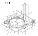
すなわちターンテーブル2は、ここでは図2,図3に示すように、複数、例えば4個の血液バッグ3…を載置,収納する有底円筒状のケース10と、載置,収納された血液バッグ3…をケース底板10aとで挟んで固定する蓋板11と、ケース10を通常の軸回り方向に回転させる回転駆動部12と、ケース10の上下面を反転させる反転駆動部13及び上下駆動部14とから構成されている。
【0013】
この場合、ケース10の内周面には複数本の環状溝10b…が軸方向(図中上下方向)に並んで穿設されており、上記蓋板11をどの環状溝10bに挿入するかによってケース底板10aと蓋板11とで形成される間隔寸法を選択できる。したがって、血液バッグ3内の血液量や血液バッグ3の種類(主にサイズ)によって血液バッグ3の厚さが変化しても血液バッグ3…はケース10内において常に確実に固定でき、ターンテーブル2の上下面反転時において、血液バッグ3…に位置ずれ、折り重なり、あるいは落下等は生じない。
ケース10の底板10aと蓋板11はX線吸収が少なく、一定以上の強度をもつカーボンファイバ等の材質で形成されており、内部の血液バッグ3…の相互位置状態が視認できるように多数の穴10c…,11a…が穿設されている。
【0014】
なお、図3中、10dはケース10内周面に前記複数本の環状溝10bに交差して形成された蓋板案内用溝、11bは蓋板11に形成されたつまみ、11cは同じく鍔部である。蓋板11は、つまみ11bを持って鍔部11cをケース10の蓋板案内用溝10dを経て所望の環状溝10bに位置を合わせて回動することで、その環状溝10b内に挿入され、血液バッグ3…を位置決め固定する。
【0015】
また、前記ケース10の外周側はコロ15で支持され、かつ、このケース外周及び回転駆動部12相互間にはベルト16が掛け回されており、ケース10は回転駆動部12の駆動により、軸回り方向に回転可能である。
【0016】
更に、ケース10と回転駆動部12が配置されたターンテーブル取付基板17の両側はコロ18で回転自在に支持され、更にスプロケット19とチェーン20を介して反転駆動部13に連係されており、基板17、換言すればケース10(ターンテーブル2)は反転駆動部13の駆動によりその上下面を反転可能である。
【0017】
前記上下機構部14は、ターンテーブル取付基板17の上下面反転の際、その基板17がターンテーブル取付面21に衝突しないように基板反転動作と同時に上昇動作をし、反転終了後に下降動作してターンテーブル2を元のX線照射位置に戻す。
【0018】
前記制御器9は、基本的には、ターンテーブル2を回転させつつX線管装置1からX線を出射させてそのターンテーブル2上の血液バッグ3…にX線照射させ、その血液バッグ3…への設定総X線照射量(必要X線照射総量)に応じた所定のX線照射量に達した際にターンテーブル2の上下面を反転させ、再びターンテーブル2を回転させつつX線管装置1からX線を出射させてそのターンテーブル2上の血液バッグ3…にX線照射させる。ここでは、上記上下機構部14の上昇,下降動作の制御も行う。
【0019】
また、制御器9は、血液バッグ3内の血液量や血液バッグ3の種類等(主にサイズや内容物の種別)を入力することにより、それに応じた1回分のX線照射量が設定され、線量計6に書込む機能をも持つ。1回分のX線照射量は、総X線照射量の1/2とするのが効率的ではあるが、ターンテーブル上下面反転の前後において1/2とは異なる比率に設定可能としてもよい。またこの場合の比率を、血液バッグ3内の血液量や血液バッグ3の種類等を入力することにより、それに応じ自動的に選定されるようにしてもよい。
【0020】
次に上述本発明装置の動作を図4を併用して説明する。
いま、ターンテーブル2には血液バッグ3…が相互位置関係を保持した状態で置かれているものとする。また、線量計6には1回分のX線照射量(ここでは血液バッグ3に照射する総X線量の1/2)が書き込まれているものとする。
【0021】
この状態において、時点t1でX線照射ボタン(図示せず)を押圧すると、制御器9が起動し、X線照射が開始されると共にターンテーブル2(ケース10)が回転される。これにより、血液バッグ3…は相互位置関係を保持したままターンテーブル2の上面において回転されつつその表面側より均等にX線照射される。この間、線量計6はプローブ5を介してX線照射線量を計測している。
【0022】
時点t2において、上記X線照射線量の計測値が線量計6に書き込まれた前記1回分のX線照射量に達すると、線量計6から制御器9に線量到達信号が出力される(図4の例では線量到達信号が立ち下がる)。これにより、制御器9はターンテーブル2の回転及びX線照射を停止させると共にターンテーブル2を上昇させる。
【0023】
時点t3において、ターンテーブル2の上昇が完了すると、ターンテーブル2の上下面を反転させる。この際、血液バッグ3…は相互位置関係を保持した状態にあり、血液バッグ3…がターンテーブル2から落下したり、位置ずれ、折り重なり等は生じない。
時点t4において、ターンテーブル2の上下面反転が完了すると、ターンテーブル2を下降させて元のX線照射位置に戻す。
【0024】
時点t5において、ターンテーブル2が下降し元のX線照射位置に戻ると、再びX線照射が開始されると共にターンテーブル2(ケース10)が回転される。これにより、血液バッグ3…は相互位置関係を保持したままターンテーブル2の上面において回転されつつその裏面側より均等にX線照射される。この間、線量計6はプローブ5を介してX線照射線量を計測している。
【0025】
時点t6において、上記X線照射線量の計測値が線量計6に書き込まれた前記1回分のX線照射量に達すると、線量計6から制御器9に線量到達信号が出力される(図4の例では線量到達信号が立ち下がる)。これにより、制御器9はターンテーブル2の回転及びX線照射を停止させ、X線照射処理を完了する。
【0026】
以上により、各血液バッグ3…のターンテーブル2上(平面上)での載置位置による照射X線量の差のみならず、血液バッグ3の厚み方向での照射X線量の差も小さくなり、各血液バッグ3…及び血液バッグ3各部における線量分布が均一化される。
【0027】
【発明の効果】
以上説明したように本発明によれば、ターンテーブルの血液バッグ載置面の上方のみからX線照射するので放射線源は1個で足り、またターンテーブルは上下面反転可能で、血液バッグを表裏面からX線照射可能であるので、血液バッグの厚み方向の線量分布均一化と装置の低価格化を両立し得る。
また、ターンテーブル上に複数の血液バッグが載置されX線照射される。すなわち、1回のX線照射で複数の血液バッグが処理されるので処理能力を低下させることはない等の効果がある。
【図面の簡単な説明】
【図1】本発明装置の一実施形態を示すブロック図である。
【図2】本発明装置のターンテーブル部分の一例を取り出して示す斜視図である。
【図3】同上ターンテーブルを構成するケース及び蓋部分の拡大分解斜視図である。
【図4】本発明装置の動作を説明するためのタイムチャートである。
【符号の説明】
1…X線管装置(放射線源)、2…ターンテーブル、3…血液バッグ、4…高電圧発生装置、5…プローブ、6…線量計、7…防護ボックス、8…冷却器、9…制御器(制御手段)、10…ケース、11…蓋板、12…回転駆動部、13…反転駆動部、14…上下機構部、15,18…コロ、16…ベルト、17…ターンテーブル取付基板、19…スプロケット、20…チェーン、21…ターンテーブル取付面。[0001]
BACKGROUND OF THE INVENTION
The present invention relates to a radiation irradiation device for a blood bag that enables uniform irradiation treatment of a plurality of blood bags.
[0002]
[Prior art]
In recent years, the onset of GVHD (Graft Versus Host Disease) due to blood transfusion has become a problem. In this prevention, X-rays and γ-rays are appropriately administered to blood before blood transfusion (including blood products separated for each blood component (red blood cells, platelets, etc.) and enclosed in a blood storage bag. The same applies in this specification). It is considered effective to inactivate lymphocytes in blood by irradiating radiation such as electron beams, for example, X-rays of 15 to 50 gray (1500 to 5000 rads).
[0003]
By the way, such irradiation with blood is usually performed in a state where the blood is put in a storage bag (this is called a blood storage bag for blood transfusion, including a blood product storage bag; the same applies in this specification). This is performed using a bag radiation irradiation apparatus. X-rays are generally used as the irradiated radiation.
[0004]
In this type of conventional X-ray irradiation apparatus, an X-ray tube device is arranged at the upper part in the apparatus housing, and a blood bag (a blood storage bag for blood transfusion into which blood for transfusion has been injected) is provided at the center of the X-ray irradiation field. The same applies in this specification), and a table on which an X-ray is irradiated is arranged. In this case, it is known that the distribution of the X-ray dose emitted from the X-ray tube apparatus is not uniform within the irradiation field. In order to improve this, a turntable is used as the table, and the turntable rotates on a plane. A large number of blood bags were placed on the top and irradiated with X-rays.
[0005]
[Problems to be solved by the invention]
However, the above prior art has a problem that the dose distribution in the thickness direction of the blood bag cannot be made uniform.
In view of this, there has been considered an apparatus in which one X-ray tube device is arranged on each of the upper and lower sides of the turntable and X-rays are irradiated from the front and back surfaces of the blood bag. However, this requires two X-ray tube devices. There is a problem that the apparatus becomes expensive.
Furthermore, the X-ray tube device is arranged on either the left or right side, and after irradiating one side surface of the blood bag with X-rays from there, the side surface of the blood bag is inverted, and then the X-ray is again applied to the blood bag. There is also an apparatus that irradiates a blood bag with X-rays from both side surfaces (front and back surfaces) by irradiation. According to this, it is possible to achieve both a uniform dose distribution in the thickness direction of the blood bag and a low price of the apparatus, but one blood bag is processed by one X-ray irradiation, and the processing capability is low. There was a problem.
[0006]
An object of the present invention is to provide a radiation irradiation apparatus for a blood bag that can achieve both a uniform dose distribution in the thickness direction of the blood bag and a low price of the apparatus, and that does not reduce the processing capacity.
[0007]
[Means for Solving the Problems]
The object is to provide a radiation irradiation device for a blood bag comprising: a radiation source disposed above or below a blood bag for irradiating the blood bag with radiation; and a control means for controlling radiation irradiation of the radiation source. A plurality of the blood bags are placed side by side, and the upper and lower surfaces of the placed plurality of blood bags are reversed around a first rotation axis, and the second is perpendicular to the first rotation axis. A turntable for rotating the plurality of blood bags placed in the direction around the rotation axis is provided, and the control means is achieved by controlling rotation and reversal of the turntable.
[0008]
According to this, a plurality of blood bags are placed on the turntable and irradiated with X-rays. That is, since a plurality of blood bags are processed by one X-ray irradiation, the processing capacity is not lowered.
One radiation source is sufficient to irradiate radiation from above or below the blood bag mounting surface of the turntable, and the turntable can be turned upside down, and the blood bag can be irradiated from the front and back surfaces. It is possible to achieve both uniform dose distribution in the thickness direction of the bag and cost reduction of the apparatus.
In addition, since the upper and lower surfaces of the turntable can be reversed while maintaining the mutual positional relationship of the plurality of blood bags on the upper surface, the blood bag does not drop, does not shift or fold when the upper and lower surfaces are reversed.
[0009]
DETAILED DESCRIPTION OF THE INVENTION
Hereinafter, embodiments of the present invention will be described with reference to the drawings.
FIG. 1 is a block diagram showing an embodiment of a radiation irradiation apparatus for blood bags according to the present invention.
In FIG. 1, 1 is a radiation source, here an X-ray tube device, 2 is a turntable on which a plurality of
[0010]
Here, one
[0011]
The turntable 2 is capable of basic rotation as a turntable (normal rotation around the axis), and in addition, a mutual positional relationship between a plurality of
[0012]
That is, as shown in FIGS. 2 and 3, the turntable 2 includes a bottomed
[0013]
In this case, a plurality of
The bottom plate 10a and the cover plate 11 of the
[0014]
In FIG. 3,
[0015]
Further, the outer peripheral side of the
[0016]
Further, both sides of the
[0017]
When the upper and lower surfaces of the
[0018]
The
[0019]
Further, the
[0020]
Next, the operation of the apparatus of the present invention will be described with reference to FIG.
Now, assume that
[0021]
In this state, when an X-ray irradiation button (not shown) is pressed at time t1, the
[0022]
When the measured value of the X-ray irradiation dose reaches the single X-ray dose written in the
[0023]
When the raising of the turntable 2 is completed at time t3, the upper and lower surfaces of the turntable 2 are reversed. At this time, the
When the upper and lower surface inversion of the turntable 2 is completed at the time t4, the turntable 2 is lowered and returned to the original X-ray irradiation position.
[0024]
When the turntable 2 descends and returns to the original X-ray irradiation position at time t5, X-ray irradiation is started again and the turntable 2 (case 10) is rotated. As a result, the
[0025]
When the measured value of the X-ray irradiation dose reaches the single X-ray dose written in the
[0026]
As described above, not only the difference in irradiation X-ray dose depending on the placement position of each
[0027]
【The invention's effect】
As described above, according to the present invention, X-ray irradiation is performed only from above the blood bag placement surface of the turntable, so that only one radiation source is required, and the turntable can be turned upside down to display the blood bag. Since X-ray irradiation can be performed from the back side, it is possible to achieve both uniform dose distribution in the thickness direction of the blood bag and low cost of the apparatus.
A plurality of blood bags are placed on the turntable and irradiated with X-rays. That is, since a plurality of blood bags are processed by one X-ray irradiation, there is an effect that the processing capacity is not lowered.
[Brief description of the drawings]
FIG. 1 is a block diagram showing an embodiment of a device of the present invention.
FIG. 2 is a perspective view showing an example of a turntable portion of the device of the present invention.
FIG. 3 is an enlarged exploded perspective view of a case and a lid part constituting the turntable.
FIG. 4 is a time chart for explaining the operation of the device of the present invention.
[Explanation of symbols]
DESCRIPTION OF
Claims (1)
Priority Applications (1)
| Application Number | Priority Date | Filing Date | Title |
|---|---|---|---|
| JP08011197A JP3775451B2 (en) | 1997-03-31 | 1997-03-31 | Radiation irradiation device for blood bag |
Applications Claiming Priority (1)
| Application Number | Priority Date | Filing Date | Title |
|---|---|---|---|
| JP08011197A JP3775451B2 (en) | 1997-03-31 | 1997-03-31 | Radiation irradiation device for blood bag |
Publications (2)
| Publication Number | Publication Date |
|---|---|
| JPH10274699A JPH10274699A (en) | 1998-10-13 |
| JP3775451B2 true JP3775451B2 (en) | 2006-05-17 |
Family
ID=13709084
Family Applications (1)
| Application Number | Title | Priority Date | Filing Date |
|---|---|---|---|
| JP08011197A Expired - Fee Related JP3775451B2 (en) | 1997-03-31 | 1997-03-31 | Radiation irradiation device for blood bag |
Country Status (1)
| Country | Link |
|---|---|
| JP (1) | JP3775451B2 (en) |
Families Citing this family (3)
| Publication number | Priority date | Publication date | Assignee | Title |
|---|---|---|---|---|
| JP4609968B2 (en) * | 2000-10-30 | 2011-01-12 | 株式会社日立メディコ | Radiation irradiation device for blood bag |
| FR2881351B1 (en) * | 2005-02-01 | 2009-01-16 | Linac Technologies Sas Soc Par | INSTALLATION AND METHOD FOR STERILIZING OBJECTS BY LOW ENERGY ELECTRON BOMBING |
| JP4870975B2 (en) * | 2005-11-09 | 2012-02-08 | 株式会社日立メディコ | Radiation irradiation equipment |
-
1997
- 1997-03-31 JP JP08011197A patent/JP3775451B2/en not_active Expired - Fee Related
Also Published As
| Publication number | Publication date |
|---|---|
| JPH10274699A (en) | 1998-10-13 |
Similar Documents
| Publication | Publication Date | Title |
|---|---|---|
| Yang et al. | An investigation of tomotherapy beam delivery | |
| JPH1147287A (en) | Rotational irradiation chamber for radiotherapy | |
| US20130177136A1 (en) | Apparatus and method of providing dual line source irradiator, dlsir | |
| JP3775451B2 (en) | Radiation irradiation device for blood bag | |
| US3715597A (en) | Rotatable neutron therapy irradiating apparatus | |
| JPH0956710A (en) | X-ray computer tomography apparatus | |
| JP4305997B2 (en) | Radiation irradiation device for blood bag | |
| EP1478408B1 (en) | Apparatus and process for irradiating product pallets | |
| JP2648405B2 (en) | Material analyzer | |
| JPH05340861A (en) | Non-destructive measuring device and method of amount of uranium included in radioactive waste product | |
| Braestrup et al. | Convergent beam irradiator: apparatus for convergent beam irradiation with stationary or moving source | |
| JP4609968B2 (en) | Radiation irradiation device for blood bag | |
| JP3609270B2 (en) | Granular rolling device and sterilization method | |
| JPH07185024A (en) | Radiotherapeutic device | |
| JPH047231B2 (en) | ||
| JPH08184700A (en) | Electron beam irradiation device | |
| JP2001249200A (en) | X-ray/electron beam rotary type irradiating device and method therefor | |
| JPH08182768A (en) | Radiation beam irradiating apparatus | |
| JP2000325441A (en) | Electron beam irradiation method | |
| JPS5934078Y2 (en) | Aperture device for surgical fluoroscopy equipment | |
| JPS59218166A (en) | Radiation treatng apparatus | |
| JPH0111266Y2 (en) | ||
| CN114225136A (en) | Control method and control system of irradiator based on X-rays | |
| JPH05192419A (en) | Rotary irradiation therapeutic apparatus | |
| JPH07227432A (en) | Rotary balance-adjusting mechanism for radiotherapy equipment |
Legal Events
| Date | Code | Title | Description |
|---|---|---|---|
| A521 | Written amendment |
Free format text: JAPANESE INTERMEDIATE CODE: A523 Effective date: 20040216 |
|
| A621 | Written request for application examination |
Free format text: JAPANESE INTERMEDIATE CODE: A621 Effective date: 20040216 |
|
| A977 | Report on retrieval |
Free format text: JAPANESE INTERMEDIATE CODE: A971007 Effective date: 20051018 |
|
| A131 | Notification of reasons for refusal |
Free format text: JAPANESE INTERMEDIATE CODE: A131 Effective date: 20051115 |
|
| A521 | Written amendment |
Free format text: JAPANESE INTERMEDIATE CODE: A523 Effective date: 20051128 |
|
| TRDD | Decision of grant or rejection written | ||
| A01 | Written decision to grant a patent or to grant a registration (utility model) |
Free format text: JAPANESE INTERMEDIATE CODE: A01 Effective date: 20060124 |
|
| A61 | First payment of annual fees (during grant procedure) |
Free format text: JAPANESE INTERMEDIATE CODE: A61 Effective date: 20060214 |
|
| R150 | Certificate of patent or registration of utility model |
Free format text: JAPANESE INTERMEDIATE CODE: R150 |
|
| FPAY | Renewal fee payment (event date is renewal date of database) |
Free format text: PAYMENT UNTIL: 20100303 Year of fee payment: 4 |
|
| FPAY | Renewal fee payment (event date is renewal date of database) |
Free format text: PAYMENT UNTIL: 20110303 Year of fee payment: 5 |
|
| FPAY | Renewal fee payment (event date is renewal date of database) |
Free format text: PAYMENT UNTIL: 20130303 Year of fee payment: 7 |
|
| FPAY | Renewal fee payment (event date is renewal date of database) |
Free format text: PAYMENT UNTIL: 20140303 Year of fee payment: 8 |
|
| LAPS | Cancellation because of no payment of annual fees |