JP3772662B2 - Encoder abnormality detection device - Google Patents
Encoder abnormality detection device Download PDFInfo
- Publication number
- JP3772662B2 JP3772662B2 JP2000337101A JP2000337101A JP3772662B2 JP 3772662 B2 JP3772662 B2 JP 3772662B2 JP 2000337101 A JP2000337101 A JP 2000337101A JP 2000337101 A JP2000337101 A JP 2000337101A JP 3772662 B2 JP3772662 B2 JP 3772662B2
- Authority
- JP
- Japan
- Prior art keywords
- signal
- phase
- generated
- check
- abnormality detection
- Prior art date
- Legal status (The legal status is an assumption and is not a legal conclusion. Google has not performed a legal analysis and makes no representation as to the accuracy of the status listed.)
- Expired - Lifetime
Links
Images
Landscapes
- Transmission And Conversion Of Sensor Element Output (AREA)
Description
【0001】
【発明の属する技術分野】
本発明は、ロータリ方式およびリニア方式のエンコーダの異常検出に関するものである。
【0002】
【従来の技術】
一般にエンコーダの異常検出装置としては、Z信号をトリガ信号として用いてカウンタ値のチェックを行なう方法が知れられている(例えば、実開昭53−146893号公報参照)。
【0003】
以下、従来のエンコーダ異常検出の一例について図を参照しながら説明する。
【0004】
図5において、11はパルス発生器で、一回転の分解能を示すA相信号、B相信号、および一回転一パルスのZ信号を出力する。12はA相信号、B相信号のエッジをカウントするカウンタで、回転方向に応じてUPカウントもしくはDOWNカウントを行ない、一回転に一度リセット動作を行なう。13はデコーダで、カウンタ12のカウント値が特定値の時のみデコーダ信号Dを発生させる。
【0005】
このデコーダ信号Dを制御回路17にてZ信号をトリガとしてチェックする。そして、チェックの結果が“L”の場合に異常検出信号を出力する。
【0006】
【発明が解決しようとする課題】
しかしながら上記従来の異常検出方式においては、信号経路の断線等によってZ信号が欠相した場合に、デコーダ信号のチェックが行なわれず、異常検出の機能自体が動作しないと言う課題を有していた。
【0007】
本発明は上記従来例の課題を解決するものであり、Z信号の欠相を検出でき、十分な信頼性をもったエンコーダ異常検出装置を提供することを目的とする。
【0008】
【課題を解決するための手段】
上記の課題を解決するために本発明は、入力軸の所定回転角毎に位相のずれた2個のパルスをA相信号とB相信号として発生すると共に、入力軸一回転中の所定回転角位置で一個のパルスをZ信号として発生するパルス発生器と、前記入力軸の回転方向に応じてUPカウント、DOWNカウントを切り替え、かつ前記Z信号出力時に特定値を取るようリセット動作を行ない、かつ前記A相信号と前記B相信号のエッジをカウントするカウンタを有するエンコーダに電気的に接続され、前記カウンタの内容が特定値の時に信号Dを出力するデコーダと、前記デコーダの出力信号Dと前記A相信号もしくは前記B相信号のエッジ検出信号の論理積によりチェック信号Cを生成するチェック信号生成器と、チェック信号生成器からの信号発生時にZ信号の発生の有無を確認し、無しの場合に異常検出信号を発生するZ信号検出手段を備えたものである。
【0009】
また、駆動部の所定移動距離毎に位相のずれた2個のパルスをA相信号とB相信号として発生すると共に、駆動部の一定移動距離中の所定移動位置で一個のパルスをZ信号として発生するパルス発生器と、前記駆動部の移動方向に応じてUPカウント、DOWNカウントを切り替え、かつ前記Z信号出力時に特定値を取るようリセット動作を行ない、かつ前記A相信号と前記B相信号のエッジをカウントするカウンタを有するエンコーダに電気的に接続され、前記カウンタの内容が特定値の時に信号Dを出力するデコーダと、前記デコーダの出力信号Dと前記A相信号もしくは前記B相信号のエッジ検出信号の論理積によりチェック信号Cを生成するチェック信号生成器と、チェック信号生成器からの信号発生時にZ信号の発生の有無を確認し、無しの場合に異常検出信号を発生するZ信号検出手段を備えたものである。
【0010】
さらに、デコーダの信号出力条件のカウンタ値に許容値として幅を持たせ、発生する複数のチェック信号C(+α)‥‥‥C(0)‥‥‥C(−β)(α及びβは、0または自然数)全てにおいてZ信号無しの場合にのみ異常検出信号を発生するものである。
【0011】
【発明の実施の形態】
上記の課題を解決するために請求項1または請求項2記載の発明は、入力軸の所定回転角毎に位相のずれた2個のパルスをA相信号とB相信号として発生すると共に、入力軸一回転中の所定回転角位置で一個のパルスをZ信号として発生するパルス発生器と、前記入力軸の回転方向に応じてUPカウント、DOWNカウントを切り替え、かつ前記Z信号出力時に特定値を取るようリセット動作を行ない、かつ前記A相信号と前記B相信号のエッジをカウントするカウンタを有するエンコーダに電気的に接続され、前記カウンタの内容が特定値の時に信号Dを出力するデコーダと、前記デコーダの出力信号Dと前記A相信号もしくは前記B相信号のエッジ検出信号の論理積によりチェック信号Cを生成するチェック信号生成器と、チェック信号生成器からの信号発生時にZ信号の発生の有無を確認し、無しの場合に異常検出信号を発生するZ信号検出手段を備えたもの、または、駆動部の所定移動距離毎に位相のずれた2個のパルスをA相信号とB相信号として発生すると共に、駆動部の一定移動距離中の所定移動位置で一個のパルスをZ信号として発生するパルス発生器と、前記駆動部の移動方向に応じてUPカウント、DOWNカウントを切り替え、かつ前記Z信号出力時に特定値を取るようリセット動作を行ない、かつ前記A相信号と前記B相信号のエッジをカウントするカウンタを有するエンコーダに電気的に接続され、前記カウンタの内容が特定値の時に信号Dを出力するデコーダと、前記デコーダの出力信号Dと前記A相信号もしくは前記B相信号のエッジ検出信号の論理積によりチェック信号Cを生成するチェック信号生成器と、チェック信号生成器からの信号発生時にZ信号の発生の有無を確認し、無しの場合に異常検出信号を発生するZ信号検出手段を備えたもので、カウンタの内容が特定値の時にZ信号の有無をチェックすることにより、Z信号の欠相が検出でき、エンコーダ異常検出の信頼性を向上させることができるという作用を有する。
【0012】
また、請求項3記載の発明は、デコーダの信号出力条件のカウンタ値に許容値として幅を持たせ、発生する複数のチェック信号C(+α)‥‥‥C(0)‥‥‥C(−β)(α及びβは、0または自然数)全てにおいてZ信号無しの場合にのみ異常検出信号を発生するもので、デコーダ信号出力条件のカウンタ値に許容値として幅を持たせることにより、より自由度の高いエンコーダ異常検出装置となるという作用を有する。
【0013】
【実施例】
以下、本発明の実施例について図を参照しながら説明する。
【0014】
(実施例1)
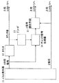
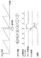
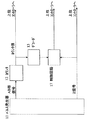
図1において、11はパルス発生器で、一回転の分解能を示すA相信号、B相信号、及び一回転一パルスのZ信号を出力する。12はA相信号、B相信号のエッジをカウントするカウンタで、回転方向に応じてUPカウントもしくはDOWNカウントを行ない、一回転に一度リセット動作を行なう。13はデコーダで、カウンタ12のカウント値が“0”の時のみデコーダ信号Dを発生させる。14はチェック信号生成器で、A相信号、B相信号のエッジパルスとデコーダ信号Dの論理積によりチェック信号Cを生成する。15はZ信号検出手段で、チェック信号CをトリガとしてZ信号を検出し、Z信号の“H”パルスを検出した場合は“異常無し”、“L”パルスを検出した場合は“異常有り”とし、異常検出信号を出力する。図2に、カウント値、AB相信号エッジパルス、デコーダ信号、チェック信号のタイミングチャートを示す。このように構成することで、エンコーダの異常検出装置を実現できる。
【0015】
なお、本実施例では、デコーダ信号を発生させるカウンタの特定値を“0”としたが、“0”でなくても同様の効果が得られる。
【0016】
(実施例2)
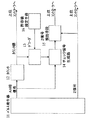
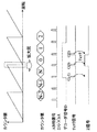
また、図3に示すように、デコーダ13に許容値設定手段16からのデータを入力し、デコーダ信号Dの出力条件に幅を持たせると、異常検出の自由度が大きくなり、より利便性が高くなる。図4にそのタイミングチャートを示し、詳細を説明する。
【0017】
実施例2では、許容値設定手段16からのデータによって決まるデコーダ信号の出力条件のカウンタ値を“N”〜“1”としている。
【0018】
この時、チェック信号は、C(−1)、C(0)、C(1)の3個発生する。Z信号検出手段15においては、これらのチェック信号全てによってZ信号をチェックするが、異常有無の判定基準は、
C(−1)のチェック結果=“L”かつ
C(0)のチェック結果=“L”かつ
C(1)のチェック結果=“L”
の時は、“異常無し”とし、
上記以外は“異常有り”として、異常検出信号を出力する。
【0019】
なお、実施例1および実施例2は、ロータリ方式のエンコーダの動作について説明したが、リニア方式のエンコーダに関しても、パルス発生器からの信号が同様であれば、図1、図2、図3、図4の内容は同じように適用でき、同様の効果が得られる。
【0020】
また、本発明のエンコーダ異常検出装置は、エンコーダの一部としてエンコーダに搭載しても、エンコーダからの出力信号としてカウンタデータ、Z信号を受ける上位コントローラ側に搭載しても、どちらでも同様の効果が得られる。
【0021】
さらに、本発明のエンコーダ異常検出装置は、従来の、Z信号をトリガにしてカウンタ値をチェックする方式のエンコーダ異常検出装置と併せて使用することにより、互いに補完し合い、より一層信頼性が向上する。
【0022】
【発明の効果】
上記の実施例から明らかなように、請求項1または請求項2記載の発明によれば、カウンタの内容が特定値の時にZ信号をチェックすることにより、Z信号の欠相が検出できるという効果をもつ。
【0023】
また、請求項3記載の発明によれば、デコーダ信号出力条件のカウンタ値に許容値として幅を持たせることにより、より自由度の高いエンコーダ異常検出装置となるという効果をもつ。
【0024】
したがって、Z信号の欠相を検出でき、十分な信頼性をもったロータリ式およびリニア式のエンコーダ異常検出装置を提供することができる。
【図面の簡単な説明】
【図1】本発明の実施例1におけるエンコーダ異常検出装置のブロック図
【図2】本発明の実施例1におけるタイミングチャート
【図3】本発明の実施例2におけるエンコーダ異常検出装置のブロック図
【図4】本発明の実施例2におけるタイミングチャート
【図5】従来のエンコーダ異常検出装置のブロック図
【符号の説明】
11 パルス発生器
12 カウンタ
13 デコーダ
14 チェック信号生成器
15 Z信号検出手段
16 許容値設定手段
17 制御回路[0001]
BACKGROUND OF THE INVENTION
The present invention relates to abnormality detection in rotary and linear encoders.
[0002]
[Prior art]
In general, an encoder abnormality detection apparatus is known in which a counter value is checked using a Z signal as a trigger signal (see, for example, Japanese Utility Model Publication No. 53-146893).
[0003]
Hereinafter, an example of conventional encoder abnormality detection will be described with reference to the drawings.
[0004]
In FIG. 5, reference numeral 11 denotes a pulse generator that outputs an A-phase signal, a B-phase signal indicating the resolution of one revolution, and a Z signal of one revolution and one pulse. A counter 12 counts the edges of the A-phase signal and B-phase signal. The counter counts up or down according to the direction of rotation, and resets once per rotation. A
[0005]
The decoder signal D is checked by the control circuit 17 using the Z signal as a trigger. When the check result is “L”, an abnormality detection signal is output.
[0006]
[Problems to be solved by the invention]
However, the conventional abnormality detection method has a problem that when the Z signal is lost due to a disconnection of the signal path, the decoder signal is not checked and the abnormality detection function itself does not operate.
[0007]
SUMMARY OF THE INVENTION The present invention solves the above-described problems of the conventional example, and an object thereof is to provide an encoder abnormality detection device that can detect an open phase of a Z signal and has sufficient reliability.
[0008]
[Means for Solving the Problems]
In order to solve the above problems, the present invention generates two pulses having a phase shift for each predetermined rotation angle of the input shaft as an A-phase signal and a B-phase signal, and a predetermined rotation angle during one rotation of the input shaft. A pulse generator for generating a single pulse as a Z signal at a position, a UP count and a DOWN count are switched according to the rotation direction of the input shaft, and a reset operation is performed to take a specific value when the Z signal is output; and A decoder electrically connected to an encoder having a counter for counting edges of the A-phase signal and the B-phase signal, and outputting a signal D when the content of the counter is a specific value; an output signal D of the decoder; A check signal generator that generates a check signal C by the logical product of the A phase signal or the edge detection signal of the B phase signal, and Z when a signal is generated from the check signal generator Check for occurrence of items, those having a Z signal detecting means for generating an abnormality detection signal when without.
[0009]
In addition, two pulses having a phase shift for each predetermined movement distance of the drive unit are generated as an A-phase signal and a B-phase signal, and one pulse is used as a Z signal at a predetermined movement position within a fixed movement distance of the drive unit. A pulse generator to be generated, and a UP operation and a DOWN count are switched according to the moving direction of the driving unit, and a reset operation is performed so as to take a specific value when the Z signal is output, and the A phase signal and the B phase signal A decoder that outputs a signal D when the content of the counter is a specific value, an output signal D of the decoder, and the A-phase signal or the B-phase signal. Check signal generator that generates check signal C by logical product of edge detection signals, and checks whether Z signal is generated when signal is generated from check signal generator , Those having a Z signal detecting means for generating an abnormality detection signal when without.
[0010]
Further, the counter value of the signal output condition of the decoder has a width as an allowable value, and a plurality of generated check signals C (+ α)... C (0)... C (−β) (α and β are An error detection signal is generated only when there is no Z signal in all (0 or natural number).
[0011]
DETAILED DESCRIPTION OF THE INVENTION
In order to solve the above problems, the invention according to claim 1 or
[0012]
According to the third aspect of the present invention, the counter value of the signal output condition of the decoder has a width as an allowable value, and a plurality of generated check signals C (+ α)... C (0). β) (α and β are 0 or a natural number). An anomaly detection signal is generated only when there is no Z signal. By making the counter value of the decoder signal output condition wider as an allowable value, it is more flexible. It has the effect | action that it becomes a high encoder abnormality detection apparatus.
[0013]
【Example】
Examples of the present invention will be described below with reference to the drawings.
[0014]
Example 1
In FIG. 1, reference numeral 11 denotes a pulse generator that outputs an A-phase signal, a B-phase signal indicating a resolution of one rotation, and a Z signal of one rotation and one pulse. A counter 12 counts the edges of the A-phase signal and B-phase signal. The counter counts up or down according to the direction of rotation, and resets once per rotation. A
[0015]
In the present embodiment, the specific value of the counter that generates the decoder signal is set to “0”, but the same effect can be obtained even if it is not “0”.
[0016]
(Example 2)
Also, as shown in FIG. 3, if the data from the allowable value setting means 16 is input to the
[0017]
In the second embodiment, the counter value of the output condition of the decoder signal determined by the data from the allowable value setting means 16 is “N” to “1”.
[0018]
At this time, three check signals C (−1), C (0), and C (1) are generated. In the Z signal detecting means 15, the Z signal is checked by all these check signals.
Check result of C (−1) = “L” and check result of C (0) = “L” and check result of C (1) = “L”
In the case of “No abnormality”,
Otherwise, “abnormal” is detected and an abnormality detection signal is output.
[0019]
In addition, although Example 1 and Example 2 demonstrated operation | movement of the encoder of a rotary system, if the signal from a pulse generator is the same also about a linear system encoder, FIG.1, FIG.2, FIG.3, The contents of FIG. 4 can be applied in the same way, and the same effect can be obtained.
[0020]
In addition, the encoder abnormality detection device of the present invention has the same effect regardless of whether it is mounted on the encoder as a part of the encoder, or on the host controller side that receives the counter data and the Z signal as an output signal from the encoder. Is obtained.
[0021]
Furthermore, the encoder abnormality detection device of the present invention complements each other and further improves reliability by using it together with the conventional encoder abnormality detection device that checks the counter value using the Z signal as a trigger. To do.
[0022]
【The invention's effect】
As is apparent from the above embodiments, according to the first or second aspect of the invention, the Z signal can be detected as a missing phase by checking the Z signal when the content of the counter is a specific value. It has.
[0023]
According to the third aspect of the present invention, there is an effect that the encoder abnormality detecting device with a higher degree of freedom can be obtained by providing a range as a permissible value for the counter value of the decoder signal output condition.
[0024]
Therefore, it is possible to provide a rotary type and linear type encoder abnormality detection device that can detect an open phase of the Z signal and has sufficient reliability.
[Brief description of the drawings]
FIG. 1 is a block diagram of an encoder abnormality detecting device in
11 Pulse generator 12
Claims (3)
前記カウンタの内容が特定値の時に信号Dを出力するデコーダと、前記デコーダの出力信号Dと前記A相信号もしくは前記B相信号のエッジ検出信号の論理積によりチェック信号Cを生成するチェック信号生成器と、チェック信号生成器からの信号発生時にZ信号の発生の有無を確認し、無しの場合に異常検出信号を発生するZ信号検出手段を備えたエンコーダ異常検出装置。Pulses that generate two pulses that are out of phase for each predetermined rotation angle of the input shaft as A-phase signals and B-phase signals and that generate one pulse as a Z signal at a predetermined rotation angle position during one rotation of the input shaft The generator and the UP count and DOWN count are switched according to the rotation direction of the input shaft, and a reset operation is performed so as to take a specific value when the Z signal is output, and the edges of the A phase signal and the B phase signal are changed. Electrically connected to an encoder having a counter to count;
A decoder that outputs a signal D when the content of the counter is a specific value, and a check signal generation that generates a check signal C by the logical product of the output signal D of the decoder and the edge detection signal of the A phase signal or the B phase signal And an encoder abnormality detection device comprising Z signal detection means for checking whether or not a Z signal is generated when a signal is generated from a check signal generator and generating an abnormality detection signal when there is no signal.
前記カウンタの内容が特定値の時に信号Dを出力するデコーダと、前記デコーダの出力信号Dと前記A相信号もしくは前記B相信号のエッジ検出信号の論理積によりチェック信号Cを生成するチェック信号生成器と、チェック信号生成器からの信号発生時にZ信号の発生の有無を確認し、無しの場合に異常検出信号を発生するZ信号検出手段を備えたエンコーダ異常検出装置。Two pulses with a phase shift for each predetermined movement distance of the drive unit are generated as an A-phase signal and a B-phase signal, and one pulse is generated as a Z signal at a predetermined movement position within a fixed movement distance of the drive unit. The pulse generator and the UP count and the DOWN count are switched according to the moving direction of the driving unit, and a reset operation is performed so as to take a specific value when the Z signal is output, and the edges of the A phase signal and the B phase signal Electrically connected to an encoder having a counter to count
A decoder that outputs a signal D when the content of the counter is a specific value, and a check signal generation that generates a check signal C by the logical product of the output signal D of the decoder and the edge detection signal of the A phase signal or the B phase signal And an encoder abnormality detection device comprising Z signal detection means for checking whether or not a Z signal is generated when a signal is generated from a check signal generator and generating an abnormality detection signal when there is no signal.
Priority Applications (1)
| Application Number | Priority Date | Filing Date | Title |
|---|---|---|---|
| JP2000337101A JP3772662B2 (en) | 2000-11-06 | 2000-11-06 | Encoder abnormality detection device |
Applications Claiming Priority (1)
| Application Number | Priority Date | Filing Date | Title |
|---|---|---|---|
| JP2000337101A JP3772662B2 (en) | 2000-11-06 | 2000-11-06 | Encoder abnormality detection device |
Publications (2)
| Publication Number | Publication Date |
|---|---|
| JP2002139350A JP2002139350A (en) | 2002-05-17 |
| JP3772662B2 true JP3772662B2 (en) | 2006-05-10 |
Family
ID=18812543
Family Applications (1)
| Application Number | Title | Priority Date | Filing Date |
|---|---|---|---|
| JP2000337101A Expired - Lifetime JP3772662B2 (en) | 2000-11-06 | 2000-11-06 | Encoder abnormality detection device |
Country Status (1)
| Country | Link |
|---|---|
| JP (1) | JP3772662B2 (en) |
Families Citing this family (2)
| Publication number | Priority date | Publication date | Assignee | Title |
|---|---|---|---|---|
| US7928725B2 (en) | 2006-03-14 | 2011-04-19 | Ntn Corporation | Rotational angle detector and rotational angle detector incorporated bearing assembly |
| CN113406979B (en) * | 2021-06-21 | 2022-11-18 | 珠海格力电器股份有限公司 | Encoder abnormality detection method, device, storage medium, controller and equipment |
Family Cites Families (3)
| Publication number | Priority date | Publication date | Assignee | Title |
|---|---|---|---|---|
| JP2685962B2 (en) * | 1990-05-22 | 1997-12-08 | 株式会社日立製作所 | Encoder error detection device |
| JPH06288791A (en) * | 1993-04-05 | 1994-10-18 | Sankyo Seiki Mfg Co Ltd | Encoder device |
| JPH09229713A (en) * | 1996-02-21 | 1997-09-05 | Mitsubishi Heavy Ind Ltd | Encoder |
-
2000
- 2000-11-06 JP JP2000337101A patent/JP3772662B2/en not_active Expired - Lifetime
Also Published As
| Publication number | Publication date |
|---|---|
| JP2002139350A (en) | 2002-05-17 |
Similar Documents
| Publication | Publication Date | Title |
|---|---|---|
| CN102803971B (en) | Rotation speed detection device with error monitoring function | |
| EP0735654B1 (en) | Improved position encoder | |
| US9007056B2 (en) | Monitoring device and monitoring method for rotary encoder | |
| JP5310107B2 (en) | Abnormality monitoring device | |
| US5652494A (en) | Angle controller for a switched reluctance drive utilizing a high frequency clock | |
| EP0251341A1 (en) | Circuit means for evaluating the movement of a code track of incremental type | |
| CN101833049A (en) | Abnormal monitoring device | |
| JP5163963B2 (en) | Abnormality monitoring device | |
| JP2794798B2 (en) | Encoder | |
| CN113884124A (en) | Self-diagnosis method and control device for incremental encoder | |
| JPS63118903A (en) | Pulse encoder | |
| JP3772662B2 (en) | Encoder abnormality detection device | |
| US9134143B2 (en) | Absolute position detector with abnormality detection function | |
| JP3989767B2 (en) | Multi-turn encoder | |
| JP3047809B2 (en) | Rotary encoder | |
| JP2010169556A (en) | Speed monitoring device | |
| JP4283931B2 (en) | Encoder signal error detection device | |
| JP4782434B2 (en) | Rotation detection device signal processing device | |
| JP3951634B2 (en) | Physical quantity detection circuit | |
| JP3144877B2 (en) | Backup type absolute position encoder | |
| JP3448664B2 (en) | Multi-turn absolute encoder | |
| JPH09105646A (en) | Rotary encoder and rotary encoder system | |
| JP2893851B2 (en) | Absolute position detection method | |
| JP2587465B2 (en) | Pulse encoder error detection device | |
| JP4419225B2 (en) | Rotary encoder |
Legal Events
| Date | Code | Title | Description |
|---|---|---|---|
| A621 | Written request for application examination |
Free format text: JAPANESE INTERMEDIATE CODE: A621 Effective date: 20040412 |
|
| RD01 | Notification of change of attorney |
Free format text: JAPANESE INTERMEDIATE CODE: A7421 Effective date: 20050630 |
|
| A977 | Report on retrieval |
Free format text: JAPANESE INTERMEDIATE CODE: A971007 Effective date: 20060117 |
|
| TRDD | Decision of grant or rejection written | ||
| A01 | Written decision to grant a patent or to grant a registration (utility model) |
Free format text: JAPANESE INTERMEDIATE CODE: A01 Effective date: 20060124 |
|
| A61 | First payment of annual fees (during grant procedure) |
Free format text: JAPANESE INTERMEDIATE CODE: A61 Effective date: 20060206 |
|
| R151 | Written notification of patent or utility model registration |
Ref document number: 3772662 Country of ref document: JP Free format text: JAPANESE INTERMEDIATE CODE: R151 |
|
| FPAY | Renewal fee payment (event date is renewal date of database) |
Free format text: PAYMENT UNTIL: 20100224 Year of fee payment: 4 |
|
| FPAY | Renewal fee payment (event date is renewal date of database) |
Free format text: PAYMENT UNTIL: 20100224 Year of fee payment: 4 |
|
| FPAY | Renewal fee payment (event date is renewal date of database) |
Free format text: PAYMENT UNTIL: 20110224 Year of fee payment: 5 |
|
| FPAY | Renewal fee payment (event date is renewal date of database) |
Free format text: PAYMENT UNTIL: 20120224 Year of fee payment: 6 |
|
| FPAY | Renewal fee payment (event date is renewal date of database) |
Free format text: PAYMENT UNTIL: 20130224 Year of fee payment: 7 |
|
| FPAY | Renewal fee payment (event date is renewal date of database) |
Free format text: PAYMENT UNTIL: 20130224 Year of fee payment: 7 |
|
| FPAY | Renewal fee payment (event date is renewal date of database) |
Free format text: PAYMENT UNTIL: 20140224 Year of fee payment: 8 |
|
| EXPY | Cancellation because of completion of term |