JP3772601B2 - Ultrasonic generator - Google Patents
Ultrasonic generator Download PDFInfo
- Publication number
- JP3772601B2 JP3772601B2 JP24667699A JP24667699A JP3772601B2 JP 3772601 B2 JP3772601 B2 JP 3772601B2 JP 24667699 A JP24667699 A JP 24667699A JP 24667699 A JP24667699 A JP 24667699A JP 3772601 B2 JP3772601 B2 JP 3772601B2
- Authority
- JP
- Japan
- Prior art keywords
- horn
- ultrasonic generator
- ultrasonic
- generator according
- resonance plate
- Prior art date
- Legal status (The legal status is an assumption and is not a legal conclusion. Google has not performed a legal analysis and makes no representation as to the accuracy of the status listed.)
- Expired - Fee Related
Links
- 239000000725 suspension Substances 0.000 claims description 2
- 230000003071 parasitic effect Effects 0.000 description 5
- 239000002184 metal Substances 0.000 description 4
- 229910052751 metal Inorganic materials 0.000 description 3
- PXHVJJICTQNCMI-UHFFFAOYSA-N Nickel Chemical compound [Ni] PXHVJJICTQNCMI-UHFFFAOYSA-N 0.000 description 2
- 238000010586 diagram Methods 0.000 description 2
- 239000000463 material Substances 0.000 description 2
- 229910000838 Al alloy Inorganic materials 0.000 description 1
- RTAQQCXQSZGOHL-UHFFFAOYSA-N Titanium Chemical compound [Ti] RTAQQCXQSZGOHL-UHFFFAOYSA-N 0.000 description 1
- 229910052782 aluminium Inorganic materials 0.000 description 1
- XAGFODPZIPBFFR-UHFFFAOYSA-N aluminium Chemical compound [Al] XAGFODPZIPBFFR-UHFFFAOYSA-N 0.000 description 1
- DMFGNRRURHSENX-UHFFFAOYSA-N beryllium copper Chemical compound [Be].[Cu] DMFGNRRURHSENX-UHFFFAOYSA-N 0.000 description 1
- 230000000694 effects Effects 0.000 description 1
- 229910001234 light alloy Inorganic materials 0.000 description 1
- 229910001092 metal group alloy Inorganic materials 0.000 description 1
- 229910052759 nickel Inorganic materials 0.000 description 1
- 239000010936 titanium Substances 0.000 description 1
- 229910052719 titanium Inorganic materials 0.000 description 1
- 238000003466 welding Methods 0.000 description 1
Images
Classifications
-
- A—HUMAN NECESSITIES
- A45—HAND OR TRAVELLING ARTICLES
- A45D—HAIRDRESSING OR SHAVING EQUIPMENT; EQUIPMENT FOR COSMETICS OR COSMETIC TREATMENTS, e.g. FOR MANICURING OR PEDICURING
- A45D2200/00—Details not otherwise provided for in A45D
- A45D2200/20—Additional enhancing means
- A45D2200/207—Vibration, e.g. ultrasound
Landscapes
- Apparatuses For Generation Of Mechanical Vibrations (AREA)
Description
【0001】
【発明の属する技術分野】
本発明はホーンを備えている超音波発生装置に関するものである。
【0002】
【従来の技術】
振動子部とホーンとから形成されて振動子部によって電気振動を機械振動に変換し、ホーンで振動振幅を増大する超音波発生装置は、一般に大型で重量も大であることから、振動子部とホーンとを合わせた長さが発生する超音波の波長のほぼ1/2に相当する大きさに小型化するとともに、寄生振動の発生を抑制して振動の分布を均一にするために反作用体を設けたものが特開平7−2231号公報に示されている。
【0003】
【発明が解決しようとする課題】
しかし、上記公報に示されたものでは、寄生振動の抑制及び超音波出力面全体にわたり振動振幅を一定で均一とするために設けた反作用体が占有スペースや重量を増加させるものとなっており、大幅な小型軽量化を図ることは困難である。
【0004】
本発明はこのような点に鑑みなされたものであって、その目的とするところは余分な寄生振動の発生の抑制と出力面全体にわたる振動振幅の均一化を図りつつ小型軽量化を図る超音波発生装置を提供するにある。
【0005】
【課題を解決するための手段】
しかして本発明は、超音波振動を発生させる振動子部と、振動子部の振動を増幅するホーンとを備えるとともに振動子部とホーンとを合わせた長さが発生する超音波の波長のほぼ1/2となっている超音波発生装置であって、振動子部には複数のホーンが並行して取り付けられており、各ホーンの出力側が共振板で連結されているとともに、ホーンの出力側と共振板との連結部が共振板の横振動共振の節となっていることに特徴を有している。複数のホーンの先端の出力側を共振板で連結することで、寄生振動の発生の抑制及び出力面全体にわたる振動振幅の均一化を図ったものである。
【0006】
このものにおいては、振動子部とホーンとの接続部を発生する振動の節平面とするとともに機械的固定点とすればよい。
【0007】
振動子部は圧電素子を駆動源とするものや磁歪素子を駆動源とするものを好適に用いることができる。
【0008】
複数のホーンは一体物として形成されていることが好ましく、またホーンはその基端から先端にかけて湾曲した側面を備えたもの、特に指数または指数状に形成されたものや懸垂面を備えたものを好適に用いることができるが、一様断面を持つものであってもよく、その振動子部側と出力側とを結ぶ方向と直交する断面が円断面となっているものであってもよい。
【0010】
そして、この超音波発生装置は、共振板が毛髪に接触して毛髪に超音波振動を与える部材であって、毛髪のスタイリング用に好適に用いることができる。
【0011】
【発明の実施の形態】
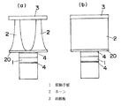
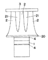
以下本発明を実施の形態の一例に基づいて詳述すると、図1において、振動子部1は伝導性金属シート4(ニッケルまたはベリリウム銅からなるものが好ましい)を間に挟み込んだ圧電素子または磁歪素子を駆動源として電気振動を機械振動に変換するもので、円柱状に形成されている振動子部1の一端側にはベース20を介して2本のホーン2,2が取り付けられている。ここにおけるホーン2は、両側面が湾曲面となっている板状のもので、太くなっている基端側がベース20に接続されて、細くなっている先端側が出力側となっており、2本のホーン2,2は平行に並んでいる。そしてホーン2の出力側である先端側には平板状の共振板3が取り付けられて、2本のホーン2,2の出力側は共振板3を介して連結されたものとなっている。なお、図示例では一枚の共振板3を2つのホーン2,2に跨らせて取り付けているが、複数枚の共振板3を夫々2つのホーン2,2に跨らせて取り付けてもよい。
【0012】
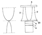
この超音波発生装置においては、図2に示すように、振動子部とホーンとを合わせた長さが発生する超音波の波長のほぼ1/2となるように(なお、図では振動の振幅を便宜のために本来の縦波を横波に変換して示している)しており、ベース20が節平面となる半波長共振器を構成している。このためにベース20での振幅が零に等しく、このベース20を機械的固定点として使用する。
【0013】
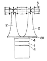
そして、共振板3はホーン2の振動に合わせてホーン2の駆動周波数で共振するようにしておくのであるが、この時、図3に示すようにホーン2の出力側と共振板3との連結点が共振板3の横振動共振の節となるようにすることで、ホーン2先端の超音波振動を能率良く共振板3に伝達することができるようにしている。
【0014】
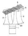
ホーン2の数は2つに限定されるものではなく、図5に示すように、3つ以上であってもよい。また、複数のホーン2,2は金属塊に溝21を切削加工することで形成した一体物であってもよく、ベース20もホーン2と一体に形成することができる。
【0015】
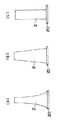
ホーン2としては、その基端から先端にかけて湾曲した側面を備えたもの、特に図6(a)に示すように指数または指数状に形成されたものや、懸垂面を備えたものを好適に用いることができるが、図6(b)に示すように、両側面が傾斜した平面となっているもの、図6(c)に示すように、一様断面を持つものであってもよく、さらにはその振動子部側と出力側とを結ぶ方向と直交する断面が図示例のような角型断面ではなく、円断面を持つものであってもよい。さらにホーン2はアルミニウムまたはアルミニウム合金のような軽金属または軽合金で形成するが、チタンなどの金属で形成してもよい。
【0016】
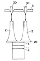
共振板3は図示例では図4に示すように、ホーン2に対してボルト30止めによって着脱自在に取り付けるものを用いて、共振板3の損傷時に共振板3のみの交換を行うことができるようにしているが、切削加工等によりホーン2と一体のものとして形成したものであってもよい。また、共振板3は前述の共振条件を満足するのであれば、ホーン2と同種の材質で形成しても異種の材質で形成してもよい。
【0017】
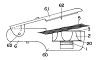
図7及び図8は上記超音波発生装置を用いたヘアセッターを示しており、超音波発生装置を埋め込むとともに共振板3を表面に露出させた本体6と、この本体6に軸63で回動自在に取り付けた回動体61とからなり、回動体61に設けた押さえ板62と、ベース20を本体6に固定することで本体6に取り付けた超音波発生装置の共振板3との間で毛髪5を挟み込み、共振板3から超音波振動を毛髪5に与えることによって毛髪スタイリング(くせ付け)を行う。
【0018】
【発明の効果】
以上のように本発明においては、振動子部に複数のホーンを並行して取り付けて、各ホーンの出力側を共振板で連結しているために、寄生振動の発生を抑制することができるとともに、出力面全体にわたる振動振幅の均一化を図ることができるものであり、しかも反作用体を設けたものに比して、小型軽量化を図ることができる。特にホーンの出力側と共振板との連結部を共振板の横振動共振の節としているために、効率の良い超音波振動発生を行うことができるものである。
【0019】
そして、振動子部とホーンとの接続部を発生する振動の節平面とするとともに機械的固定点とすることで、効率の良い超音波発生を行うことができる。
【0020】
そして該超音波発生装置は、共振板を毛髪に接触させて毛髪に超音波振動を与える毛髪スタイリング用に好適に用いることができるが、このほか、超音波溶着や超音波加工等の種々の用途に利用することができるものであり、特に共振板を用途に応じたものとすることで、通常の超音波発生装置に比してさらに広範囲な利用を図ることができる。
【図面の簡単な説明】
【図1】本発明の実施の形態の一例を示すもので、(a)は正面図、(b)は側面図である。
【図2】同上の超音波振動についての説明図である。
【図3】同上の共振板の共振についての説明図である。
【図4】同上の部分断面図である。
【図5】他例の正面図である。
【図6】 (a)(b)(c)は夫々ホーンの形状例を示す正面図である。
【図7】超音波発生装置を用いたヘアセッターの概略図である。
【図8】同上の説明図である。
【符号の説明】
1 振動子部
2 ホーン
3 共振板[0001]
BACKGROUND OF THE INVENTION
The present invention relates to an ultrasonic generator equipped with a horn.
[0002]
[Prior art]
An ultrasonic generator that is formed from a vibrator unit and a horn, converts electrical vibration into mechanical vibration by the vibrator unit, and increases the vibration amplitude by the horn is generally large and heavy. In order to reduce the size of the combined length of the horn and the horn to a size corresponding to almost half of the wavelength of the generated ultrasonic wave, and to suppress the occurrence of parasitic vibration and make the distribution of vibration uniform Japanese Patent Application Laid-Open No. 7-2231 is provided.
[0003]
[Problems to be solved by the invention]
However, in the above-mentioned publication, the reaction body provided to suppress the parasitic vibration and make the vibration amplitude constant and uniform over the entire ultrasonic output surface increases the occupied space and weight. It is difficult to achieve a significant reduction in size and weight.
[0004]
The present invention has been made in view of these points, and an object of the present invention is to reduce the size and weight of the ultrasonic wave while suppressing the generation of extra parasitic vibration and equalizing the vibration amplitude over the entire output surface. To provide a generator.
[0005]
[Means for Solving the Problems]
Accordingly, the present invention includes a transducer unit that generates ultrasonic vibrations and a horn that amplifies the vibrations of the transducer unit, and has a combined length of the transducer unit and the horn. The ultrasonic generator is a half, and a plurality of horns are attached to the transducer portion in parallel, and the output side of each horn is connected by a resonance plate, and the output side of the horn The connecting portion between the resonator plate and the resonance plate is a node of transverse vibration resonance of the resonance plate . By connecting the output sides of the tips of a plurality of horns with a resonance plate, the occurrence of parasitic vibration is suppressed and the vibration amplitude is made uniform over the entire output surface.
[0006]
In this case, the connecting portion between the vibrator portion and the horn may be a nodal plane of vibration to be generated and a mechanical fixing point.
[0007]
As the vibrator unit, a piezoelectric element as a driving source or a magnetostrictive element as a driving source can be suitably used.
[0008]
The plurality of horns are preferably formed as a single body, and the horn has a curved side surface from its proximal end to the distal end, particularly an index or index-shaped one or a suspension surface. Although it can be used preferably, it may have a uniform cross section, or a cross section perpendicular to the direction connecting the transducer part side and the output side may be a circular cross section .
[0010]
And this ultrasonic generator is a member which a resonance plate contacts with hair and gives ultrasonic vibration to hair, Comprising: It can be used suitably for hair styling.
[0011]
DETAILED DESCRIPTION OF THE INVENTION
Hereinafter, the present invention will be described in detail based on an example of the embodiment. In FIG. 1, the
[0012]
In this ultrasonic generator, as shown in FIG. 2, the combined length of the transducer part and the horn is approximately half the wavelength of the generated ultrasonic wave (in the figure, the amplitude of vibration). For the sake of convenience, the original longitudinal wave is shown as being converted into a transverse wave), and the
[0013]
The
[0014]
The number of
[0015]
As the
[0016]
In the illustrated example, as shown in FIG. 4, the
[0017]
7 and 8 show a hair setter using the above-described ultrasonic generator, a main body 6 in which the ultrasonic generator is embedded and the
[0018]
【The invention's effect】
As described above, in the present invention, since a plurality of horns are attached in parallel to the vibrator portion and the output side of each horn is connected by a resonance plate, the occurrence of parasitic vibration can be suppressed. Further, it is possible to make the vibration amplitude uniform over the entire output surface, and it is possible to reduce the size and weight as compared with the case where the reaction body is provided. In particular, since the connecting portion between the output side of the horn and the resonance plate is used as a node of the transverse vibration resonance of the resonance plate, efficient ultrasonic vibration generation can be performed.
[0019]
Further, by using a vibration nodal plane for generating a connection portion between the vibrator portion and the horn and using a mechanical fixing point, efficient ultrasonic generation can be performed .
[0020]
The ultrasonic generator can be suitably used for hair styling that brings ultrasonic vibrations into the hair by bringing the resonance plate into contact with the hair, but in addition to various uses such as ultrasonic welding and ultrasonic processing. In particular, by making the resonance plate suitable for the application, it can be used in a wider range than a normal ultrasonic generator.
[Brief description of the drawings]
FIG. 1 shows an example of an embodiment of the present invention, where (a) is a front view and (b) is a side view.
FIG. 2 is an explanatory diagram of ultrasonic vibrations as described above.
FIG. 3 is an explanatory view of resonance of the above-described resonance plate.
FIG. 4 is a partial sectional view of the above.
FIG. 5 is a front view of another example.
FIGS. 6A, 6B, and 6C are front views showing examples of horn shapes, respectively.
FIG. 7 is a schematic view of a hair setter using an ultrasonic generator.
FIG. 8 is an explanatory diagram of the above.
[Explanation of symbols]
1
Claims (12)
Priority Applications (1)
| Application Number | Priority Date | Filing Date | Title |
|---|---|---|---|
| JP24667699A JP3772601B2 (en) | 1999-08-31 | 1999-08-31 | Ultrasonic generator |
Applications Claiming Priority (1)
| Application Number | Priority Date | Filing Date | Title |
|---|---|---|---|
| JP24667699A JP3772601B2 (en) | 1999-08-31 | 1999-08-31 | Ultrasonic generator |
Publications (2)
| Publication Number | Publication Date |
|---|---|
| JP2001070881A JP2001070881A (en) | 2001-03-21 |
| JP3772601B2 true JP3772601B2 (en) | 2006-05-10 |
Family
ID=17151969
Family Applications (1)
| Application Number | Title | Priority Date | Filing Date |
|---|---|---|---|
| JP24667699A Expired - Fee Related JP3772601B2 (en) | 1999-08-31 | 1999-08-31 | Ultrasonic generator |
Country Status (1)
| Country | Link |
|---|---|
| JP (1) | JP3772601B2 (en) |
Families Citing this family (4)
| Publication number | Priority date | Publication date | Assignee | Title |
|---|---|---|---|---|
| JP4529313B2 (en) * | 2001-03-27 | 2010-08-25 | パナソニック電工株式会社 | Ultrasonic generator |
| JP2006334110A (en) * | 2005-06-01 | 2006-12-14 | Matsushita Electric Works Ltd | Ultrasonic hair treating device |
| JP4501828B2 (en) * | 2005-09-27 | 2010-07-14 | パナソニック電工株式会社 | Ultrasonic hair treatment equipment |
| KR100830530B1 (en) | 2007-01-09 | 2008-05-21 | (주)푸로맥스 | Portable skin beauty instruments |
-
1999
- 1999-08-31 JP JP24667699A patent/JP3772601B2/en not_active Expired - Fee Related
Also Published As
| Publication number | Publication date |
|---|---|
| JP2001070881A (en) | 2001-03-21 |
Similar Documents
| Publication | Publication Date | Title |
|---|---|---|
| JP4545323B2 (en) | Ultrasonic transducer with improved compression pressure transmission | |
| US4706230A (en) | Underwater low-frequency ultrasonic wave transmitter | |
| US7285895B2 (en) | Ultrasonic medical device and method | |
| JP5859509B2 (en) | Ultrasonic transducer system | |
| US20070080609A1 (en) | Low loss ultrasound transducers | |
| JP3772601B2 (en) | Ultrasonic generator | |
| JP4529313B2 (en) | Ultrasonic generator | |
| JPH0670565A (en) | Ultrasonic oscillator and ultrasonic actuator | |
| JP3972610B2 (en) | Ultrasonic beauty device | |
| CN214682736U (en) | Ultrasonic cutter transducer and ultrasonic surgical instrument | |
| JP6432069B2 (en) | Focused ultrasonic generator | |
| JP4665716B2 (en) | Ultrasonic vibrator for hair styling | |
| KR20170087308A (en) | Line-focused ultrasound transducer | |
| JP2618044B2 (en) | Ultrasound therapy equipment | |
| CN114453228A (en) | An ultrasonic transmission component | |
| JP4419774B2 (en) | Ultrasonic beauty equipment | |
| JPS6149670A (en) | Cantilever beam-shaped supersonic twisted elliptical vibrator | |
| JP6248290B2 (en) | Focused ultrasonic generator | |
| JP7796393B2 (en) | Ultrasonic vibration generator and hair treatment device | |
| JPH0627127Y2 (en) | Ultrasonic transducer | |
| JP2003112120A (en) | Langevin type vibrator | |
| KR100716467B1 (en) | Ultrasonic piezoelectric vibrator | |
| JP2026013977A (en) | vibrator | |
| JP2003275684A (en) | Ultrasonic generator and ultrasonic beauty instrument using the same | |
| JP2022037621A (en) | Ultrasonic coupling oscillation device |
Legal Events
| Date | Code | Title | Description |
|---|---|---|---|
| A977 | Report on retrieval |
Free format text: JAPANESE INTERMEDIATE CODE: A971007 Effective date: 20051014 |
|
| A131 | Notification of reasons for refusal |
Free format text: JAPANESE INTERMEDIATE CODE: A131 Effective date: 20051018 |
|
| A521 | Written amendment |
Free format text: JAPANESE INTERMEDIATE CODE: A523 Effective date: 20051219 |
|
| TRDD | Decision of grant or rejection written | ||
| A01 | Written decision to grant a patent or to grant a registration (utility model) |
Free format text: JAPANESE INTERMEDIATE CODE: A01 Effective date: 20060124 |
|
| A61 | First payment of annual fees (during grant procedure) |
Free format text: JAPANESE INTERMEDIATE CODE: A61 Effective date: 20060206 |
|
| FPAY | Renewal fee payment (event date is renewal date of database) |
Free format text: PAYMENT UNTIL: 20090224 Year of fee payment: 3 |
|
| S533 | Written request for registration of change of name |
Free format text: JAPANESE INTERMEDIATE CODE: R313533 |
|
| FPAY | Renewal fee payment (event date is renewal date of database) |
Free format text: PAYMENT UNTIL: 20090224 Year of fee payment: 3 |
|
| R350 | Written notification of registration of transfer |
Free format text: JAPANESE INTERMEDIATE CODE: R350 |
|
| FPAY | Renewal fee payment (event date is renewal date of database) |
Free format text: PAYMENT UNTIL: 20100224 Year of fee payment: 4 |
|
| FPAY | Renewal fee payment (event date is renewal date of database) |
Free format text: PAYMENT UNTIL: 20100224 Year of fee payment: 4 |
|
| FPAY | Renewal fee payment (event date is renewal date of database) |
Free format text: PAYMENT UNTIL: 20110224 Year of fee payment: 5 |
|
| LAPS | Cancellation because of no payment of annual fees |