JP3768025B2 - Seismic device - Google Patents
Seismic device Download PDFInfo
- Publication number
- JP3768025B2 JP3768025B2 JP06486199A JP6486199A JP3768025B2 JP 3768025 B2 JP3768025 B2 JP 3768025B2 JP 06486199 A JP06486199 A JP 06486199A JP 6486199 A JP6486199 A JP 6486199A JP 3768025 B2 JP3768025 B2 JP 3768025B2
- Authority
- JP
- Japan
- Prior art keywords
- axis direction
- direction moving
- moving frame
- frame
- hydraulic cylinder
- Prior art date
- Legal status (The legal status is an assumption and is not a legal conclusion. Google has not performed a legal analysis and makes no representation as to the accuracy of the status listed.)
- Expired - Fee Related
Links
Images


Description
【0001】
【発明の属する技術分野】
本発明は、地震の疑似体験等を行うために設けられる起震装置の改良に関するものである。
【0002】
【従来の技術】
地震の揺れを疑似体験させる起震装置を車両に搭載して巡回可能とした起震車が知られている。
【0003】
従来、この種の起震装置として、例えば図5に示すものが、特開平7−134541号公報に開示されている。これについて説明すると、起震車1にユニット化された起震装置2が搭載され、この起震装置2は被験者を乗せる起震室3を所定の振動パターンで揺れ動かし、起震室3に被験者が乗って防災行動の訓練を行える。
【0004】
起震装置2は、車体に対して垂直方向(図においてZ軸方向)に往復動する第一フレームと、第一フレームに対して車両の前後方向(図においてX軸方向)について往復動する第二フレームを備え、起震室3を2軸方向に揺れ動かすようになっている。
【0005】
【発明が解決しようとする課題】
しかしながら、このような従来の起震装置2にあっては、第一、第二フレームが垂直方向に積み重ねられているため、起震室3の床が高くなって乗降性が悪くなったり、起震室の天井高さを十分に確保できない。
【0006】
また、第一フレームを垂直方向に駆動する油圧シリンダには第一フレームの重量だけでなく第二フレームの重量も働くため、この油圧シリンダに要求される駆動力が大きくなり、装置の大型化や動力損失の増大を招く。
【0007】
このため、起震室を上下、前後、左右の3軸方向に揺れ動かす起震装置の場合、に3つのフレームを垂直方向に積み重ねると、起震装置が大型化し、起震室への乗降性が悪化するため、その実現が難しいという問題点があった。
【0008】
本発明は上記の問題点を鑑みてなされたものであり、装置の小型化をはかり、三軸方向に動かせる起震装置を提供することを目的とする。
【0009】
【課題を解決するための手段】
第1の発明は、互いに直交して略水平方向に往復動するX軸方向移動フレームおよびY軸方向移動フレームと、略垂直方向に往復動するZ軸方向移動フレームと、Z軸方向移動フレームをY軸方向移動フレームに支持する手段と、Y軸方向移動フレームをX軸方向移動フレームに支持する手段とを備え、Y軸方向移動フレームをX軸方向移動フレームの内側に配置し、車体に固定されるサブフレームと、前記X軸方向移動フレームを前記サブフレームに支持する手段とを備え、前記X軸方向移動フレームを前記サブフレームの内側に配置し、サブフレームに対してX軸方向移動フレームを往復動させるX軸方向移動用油圧シリンダと、X軸方向移動フレームに対してY軸方向移動フレームを往復動させるY軸方向移動用油圧シリンダとを備え、Y軸方向移動フレームとZ軸方向移動フレームの間に伸縮可能に介装される複数のリンク機構と、各リンク機構の伸縮動作を互いに連動させる連動フレームと、Y軸方向移動フレームと連動フレームの間に介装されるZ軸方向移動用油圧シリンダとを備え、Z軸方向移動用油圧シリンダの伸縮作動によって各リンク機構が伸縮作動してZ軸方向移動フレームを垂直方向に平行移動させる構成とし、Y軸方向移動用油圧シリンダとZ軸方向移動用油圧シリンダをY軸方向移動フレームの上面から突出する第一、第二ブラケットにそれぞれ結合するものとした。
【0012】
第2の発明は、第1の発明において、Y軸方向移動用油圧シリンダを前記X軸方向移動フレームに支持する第三ブラケットを備え、前記第三ブラケットを前記X軸方向移動フレームの側部から突出させて前記サブフレームの下方に配置するものとした。
【0013】
【発明の作用および効果】
第1の発明において、X軸方向移動フレームの内側にY軸方向移動フレームが配置される構造のため、これらが互いに積み重ねられる従来構造に比べて、起震装置の高さを低くでき、起震室の床を低くして乗降性を高めるとともに、車両の限られたスペースにおいて起震室の天井高さを十分に確保できる。
【0014】
また、Z軸方向移動フレームを駆動するアクチュエータにはY軸方向移動フレームやX軸方向移動フレームの重量が働くことなく、アクチュエータに要求される駆動力が小さくて済み、装置の小型化や動力損失の低減がはかれる。
【0015】
そして、サブフレームの内側にX軸方向移動フレームが配置される構造のため、これらが互いに積み重ねられる従来構造に比べて、起震装置の高さを低くでき、起震室の床を低くして乗降性を高めるとともに、車両の限られたスペースにおいて起震室の天井高さを十分に確保できる。
【0016】
そして、Y軸方向移動用油圧シリンダをY軸方向移動フレームの上方かつX軸方向移動フレームの下方に配置する構造により、Y軸方向移動用油圧シリンダを介装するスペースによってX軸方向移動フレームが大型化することを抑えられる。
【0017】
第2の発明において、Y軸方向移動用油圧シリンダを支持する第三ブラケットをサブフレームの下方に配置する構造により、Y軸方向移動用油圧シリンダのストローク量を確保するとともに、サブフレームの大型化が抑えられる。
【0018】
【発明の実施の形態】
以下、本発明を起震車に搭載される起震装置に適用した実施の形態を添付図面に基づいて説明する。
【0019】
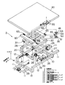
図1に示すように、起震装置2は、車体に固定されるサブフレーム10と、サブフレーム10に対して車両の前後方向(図においてX軸方向)に往復動するX軸方向移動フレーム20と、X軸方向移動フレーム20に対して車両の左右方向(図においてY軸方向)に往復動するY軸方向移動フレーム30と、Y軸方向移動フレーム30に対して垂直方向(図においてZ軸方向)に往復動するZ軸方向移動フレーム40とを備え、Z軸方向移動フレーム40上に設けられる図示しない起震室を前後、左右、上下の3軸方向に揺れ動かすことができる。
【0020】
サブフレーム10にX軸方向移動フレーム20を支持する手段として、サブフレーム10には4つのリニアレール18が固定される一方、X軸方向移動フレーム20には各リニアレール18に摺動可能に係合する4つのリニアガイドブロック28が固定される。各リニアレール18は車両の前後方向に延び、各リニアガイドブロック28を介してX軸方向移動フレーム20を車両の前後方向に平行移動可能に支持している。
【0021】
サブフレーム10とX軸方向移動フレーム20の間にX軸方向移動用油圧シリンダ29が介装され、X軸方向移動用油圧シリンダ29の伸縮によってX軸方向移動フレーム20が車両の前後方向に移動する。
【0022】
X軸方向移動フレーム20にY軸方向移動フレーム30を支持する手段として、X軸方向移動フレーム20には4つのリニアレール27が固定される一方、Y軸方向移動フレーム30には各リニアレール27に摺動可能に嵌合するリニアガイドブロック37が固定される。各リニアレール27は車両の前後方向に延び、各リニアガイドブロック37を介してY軸方向移動フレーム30を車両の左右方向に平行移動可能に支持している。
【0023】
X軸方向移動フレーム20とY軸方向移動フレーム30の間にY軸方向移動用油圧シリンダ39が介装され、Y軸方向移動用油圧シリンダ39の伸縮によってY軸方向移動フレーム30が車両の左右方向に移動する。
【0024】
Y軸方向移動フレーム30にZ軸方向移動フレーム40を支持する手段として、Y軸方向移動フレーム30には4つのリニアレール34が固定される一方、Z軸方向移動フレーム40には各リニアレール34に摺動可能に嵌合するリニアガイドブロック44が固定される。各リニアレール34は垂直方向に延び、各リニアガイドブロック44を介してZ軸方向移動フレーム40を垂直方向に平行移動可能に支持している。
【0025】
Y軸方向移動フレーム30とZ軸方向移動フレーム40の間に4つのリンク機構50が伸縮可能に介装され、各リンク機構50の伸縮動作を互いに連動させる連動フレーム60が設けられる。各リンク機構50は軸55を介して回動可能に連結される一対のリンク52,54を備え、各軸55がブラケット65を介して連動フレーム60に結合される一方、リンク52の一端は軸51によりブラケット36を介してY軸方向移動フレーム30に回動可能に結合され、リンク54の一端は軸53によりブラケット46を介してZ軸方向移動フレーム40に回動可能に結合される。Y軸方向移動フレーム30と連動フレーム60の間にZ軸方向移動用油圧シリンダ49が介装され、Z軸方向移動用油圧シリンダ49の伸縮によって連動フレーム60が車両の前後方向に駆動されるのに伴い、各リンク機構50が同期して伸縮作動し、Z軸方向移動フレーム40を垂直方向に平行移動させる。
【0026】
Y軸方向移動フレーム30には連動フレーム60を着座させる4つのストッパー33が設けられる。各ストッパー33はY軸方向移動フレーム30から上方に突出し、連動フレーム60の下面を当接させることにより、各リンク機構50を介してY軸方向移動フレーム30がそれ以上に下降するのを係止する。
【0027】
サブフレーム10とX軸方向移動フレーム20とY軸方向移動フレーム30および連動フレーム60は鉄材によりそれぞれ枠状に形成される。サブフレーム10の内側にX軸方向移動フレーム20が、X軸方向移動フレーム20の内側にY軸方向移動フレーム30が、Y軸方向移動フレーム30の内側に連動フレーム60がそれぞれ配置される。
【0028】
図2は起震装置2を車両の後側から見た正面図であるが、図において6は車両のシャシーフレーム、7は後輪である。サブフレーム10は、シャシーフレーム6に結合される左右二対のロアサイドメンバ11と、各リニアレール18が結合される左右一対のアッパサイドメンバ12と、各ロアサイドメンバ11と各アッパサイドメンバ12を結んで車両の左右方向に延びる前後のフロントクロスメンバ13およびリアクロスメンバ14等によって形成される。サブフレーム10のアッパサイドメンバ12はロアサイドメンバ11より高くオフセットされる。
【0029】
図3は起震装置2を車両の左側から見た側面図である。X軸方向移動フレーム20は、各リニアガイドブロック28が結合される左右一対のサイドビーム22と、各リニアレール27が結合される前後一対のクロスビーム23等によって形成される。クロスビーム23はサイドビーム22より低くオフセットされ、X軸方向移動フレーム20の下面20aの高さをY軸方向移動フレーム30の下面30aの高さと略等しくしている。
【0030】
Y軸方向移動フレーム30はその上面から突出する第一、第二ブラケット38、35を備える。第二ブラケット35にZ軸方向移動用油圧シリンダ49のシリンダ基端部が結合される。第一ブラケット38にY軸方向移動用油圧シリンダ39のロッド先端部が結合される。第一、第二ブラケット38、35が互いに近接しているため、第一ブラケット38をY軸方向移動フレーム30の中央部に配置されず、その分Y軸方向移動用油圧シリンダ39のシリンダ基端部はY軸方向移動フレーム30の左側に突出する。X軸方向移動フレーム20の左のサイドビーム22にはその左側に突出するコの字型をした第三ブラケット25が結合され、第三ブラケット25を介してY軸方向移動用油圧シリンダ39のシリンダ基端部が結合される。
【0031】
X軸方向移動フレーム20のサイドビーム22は、クロスビーム23より高くオフセットされ、その下方に第三ブラケット25が配置され、第三ブラケット25と干渉しないようになっている。
【0032】
サブフレーム10のアッパサイドメンバ12は、ロアサイドメンバ11より高くオフセットされ、その下方に第三ブラケット25が配置され、第三ブラケット25と干渉しないようになっている。
【0033】
図4は起震装置2を上方から見た平面図であるが、サブフレーム10の内側にX軸方向移動フレーム20が、X軸方向移動フレーム20の内側にY軸方向移動フレーム30がそれぞれ配置される。
【0034】
以上のように構成されて、次に作用について説明する。
【0035】
図示しないコントローラは、予め設定された作動モードに基づいて駆動信号を出力し、サーボ機構を介してX軸方向移動用油圧シリンダ29とY軸方向移動用油圧シリンダ39およびZ軸方向移動用油圧シリンダ49の伸縮作動を制御する。これにより、起震室は起震装置によって前後、左右、上下の3軸方向に揺れ動かされ、起震室に被験者が乗って防災行動の訓練を行える。
【0036】
サブフレーム10の内側にX軸方向移動フレーム20が配置され、X軸方向移動フレーム20の内側にY軸方向移動フレーム30が配置される構造のため、これらが互いに積み重ねられる従来構造に比べて、起震装置2の高さを低くできる。すなわち、起震装置2の高さは、Y軸方向移動フレーム30とZ軸方向移動フレーム40およびリンク機構50等によって決まり、サブフレーム10とX軸方向移動フレーム20によってほとんど大きくならないで済む。こうして起震装置2の高さが抑えられることにより、起震室の床を低くして乗降性を高めるとともに、車両の限られたスペースにおいて起震室の天井高さを十分に確保できる。
【0037】
Y軸方向移動用油圧シリンダ39がY軸方向移動フレーム30の上方かつX軸方向移動フレーム20のサイドビーム22の下方に配置されているため、Y軸方向移動フレーム30が往復動するのに伴ってこれらが互いに干渉しない。このため、Y軸方向移動用油圧シリンダ39の介装スペースによって、X軸方向移動フレーム20が車両の左右方向に大型化することが抑えられ、起震装置2を車両に搭載することが可能となる。
【0038】
Y軸方向移動用油圧シリンダ39を支持するコの字型第三ブラケット25がサブフレーム10のアッパサイドメンバ12の下方に配置されているため、Y軸方向移動フレーム30が往復動するのに伴ってこれらが互いに干渉しない。このため、Y軸方向移動用油圧シリンダ39の介装スペースによって、サブフレーム10が車両の左右方向に大型化することが抑えられ、起震装置2を車両に搭載することが可能となる。
【0039】
また、Z軸方向移動用油圧シリンダ49はY軸方向移動フレーム30上に設けられ、Z軸方向移動用油圧シリンダ49の駆動力は各リンク機構50を介してZ軸方向移動フレーム40に伝えられる構造のため、Z軸方向移動用油圧シリンダ49にはY軸方向移動フレーム30やX軸方向移動フレーム20の重量が働くことなく、Z軸方向移動用油圧シリンダ49に要求される駆動力が小さくて済み、装置の小型化や動力損失の低減がはかれる。
【図面の簡単な説明】
【図1】本発明の実施の形態を示す起震装置の分解斜視図。
【図2】同じく正面図。
【図3】同じく側面図。
【図4】同じく平面図。
【図5】従来例を示す起震車の側面図。
【符号の説明】
2 起震装置
6 シャシーフレーム
10 サブフレーム
20 X軸方向移動フレーム
25 ブラケット
29 X軸方向移動用油圧シリンダ
30 Y軸方向移動フレーム
39 Y軸方向移動用油圧シリンダ
40 Z軸方向移動フレーム
49 Z軸方向移動用油圧シリンダ
50 リンク機構
60 連動フレーム[0001]
BACKGROUND OF THE INVENTION
The present invention relates to an improvement of a seismic device provided for performing a simulated earthquake experience.
[0002]
[Prior art]
There has been known a seismic vehicle that is equipped with a seismic device that simulates the shaking of an earthquake and that can be visited.
[0003]
Conventionally, as this type of seismic device, for example, one shown in FIG. 5 is disclosed in Japanese Patent Laid-Open No. 7-134541. Explaining this, the
[0004]
The
[0005]
[Problems to be solved by the invention]
However, in such a conventional
[0006]
In addition, the hydraulic cylinder that drives the first frame in the vertical direction works not only the weight of the first frame but also the weight of the second frame, so that the driving force required for this hydraulic cylinder increases, and the size of the device increases. Increases power loss.
[0007]
For this reason, in the case of a shaking device that swings the shaking room in the three directions of up, down, front, back, left and right, if the three frames are stacked vertically, the shaking device becomes larger and the boarding / exiting property to the shaking room is possible. However, it has been difficult to realize.
[0008]
The present invention has been made in view of the above-described problems, and an object of the present invention is to provide a seismic device that can be moved in three axial directions by downsizing the device.
[0009]
[Means for Solving the Problems]
According to a first aspect of the present invention, an X-axis direction moving frame and a Y-axis direction moving frame that reciprocate in a substantially horizontal direction orthogonal to each other, a Z-axis direction moving frame that reciprocates in a substantially vertical direction, and a Z-axis direction moving frame A means for supporting the Y-axis direction moving frame and a means for supporting the Y-axis direction moving frame on the X-axis direction moving frame are provided. The Y-axis direction moving frame is arranged inside the X-axis direction moving frame and fixed to the vehicle body. And a means for supporting the X-axis direction moving frame on the sub-frame, the X-axis direction moving frame is disposed inside the sub-frame, and the X-axis direction moving frame with respect to the sub-frame A reciprocating hydraulic cylinder for moving in the X-axis direction, and a Y-axis moving hydraulic cylinder for reciprocating the Y-axis moving frame with respect to the X-axis moving frame. A plurality of link mechanisms interposed between the Y-axis direction moving frame and the Z-axis direction moving frame so as to be extendable and contracted; an interlocking frame for interlocking expansion / contraction operations of each link mechanism; And a Z-axis direction moving hydraulic cylinder interposed therebetween, and each link mechanism is expanded and contracted by expansion and contraction of the Z-axis direction moving hydraulic cylinder to translate the Z-axis direction moving frame in the vertical direction. The Y-axis direction moving hydraulic cylinder and the Z-axis direction moving hydraulic cylinder are respectively coupled to the first and second brackets protruding from the upper surface of the Y-axis direction moving frame.
[0012]
According to a second invention, in the first invention, a third bracket is provided for supporting the Y-axis direction moving hydraulic cylinder on the X- axis direction moving frame, and the third bracket is disposed from a side portion of the X- axis direction moving frame. It was made to project and be arranged below the subframe.
[0013]
Operation and effect of the invention
In the first invention, since the Y-axis direction moving frame is arranged inside the X-axis direction moving frame, the height of the vibration generating device can be reduced compared to the conventional structure in which these are stacked on each other, The floor of the room can be lowered to improve the ease of getting on and off, and the ceiling height of the seismic chamber can be sufficiently secured in a limited space of the vehicle.
[0014]
Also, the actuator that drives the Z- axis direction moving frame does not work on the weight of the Y-axis direction moving frame or the X-axis direction moving frame, and the driving force required for the actuator can be reduced, resulting in smaller equipment and power loss. Can be reduced.
[0015]
And since the X-axis direction moving frame is arranged inside the subframe, the height of the seismic device can be lowered and the floor of the seismic chamber can be lowered compared to the conventional structure in which these are stacked together. In addition to improving ease of getting on and off, the ceiling height of the seismic chamber can be sufficiently secured in a limited space of the vehicle.
[0016]
Further , the structure in which the Y-axis direction moving hydraulic cylinder is disposed above the Y-axis direction moving frame and below the X-axis direction moving frame allows the X-axis direction moving frame to be separated by the space interposing the Y-axis direction moving hydraulic cylinder. Increase in size can be suppressed.
[0017]
In the second aspect of the invention, the structure in which the third bracket for supporting the Y-axis direction moving hydraulic cylinder is disposed below the subframe ensures the stroke amount of the Y-axis direction moving cylinder and enlarges the subframe. Is suppressed.
[0018]
DETAILED DESCRIPTION OF THE INVENTION
Hereinafter, an embodiment in which the present invention is applied to a seismic device mounted on a seismic vehicle will be described with reference to the accompanying drawings.
[0019]
As shown in FIG. 1, the
[0020]
As a means for supporting the X-axis
[0021]
An X-axis direction moving
[0022]
As means for supporting the Y-axis
[0023]
A Y-axis direction moving
[0024]
As means for supporting the Z-axis
[0025]
Four
[0026]
The Y-axis
[0027]
The
[0028]
FIG. 2 is a front view of the
[0029]
FIG. 3 is a side view of the
[0030]
The Y-axis
[0031]
The
[0032]
The
[0033]
FIG. 4 is a plan view of the
[0034]
Next, the operation will be described.
[0035]
A controller (not shown) outputs a drive signal based on a preset operation mode, and via an servo mechanism, an X-axis direction moving
[0036]
Since the X-axis
[0037]
Since the Y-axis direction moving
[0038]
Since the U-shaped
[0039]
The Z-axis direction moving
[Brief description of the drawings]
FIG. 1 is an exploded perspective view of a seismic device showing an embodiment of the present invention.
FIG. 2 is a front view of the same.
FIG. 3 is a side view of the same.
FIG. 4 is a plan view of the same.
FIG. 5 is a side view of a seismic vehicle showing a conventional example.
[Explanation of symbols]
2 Seismic device 6
Claims (2)
Priority Applications (1)
| Application Number | Priority Date | Filing Date | Title |
|---|---|---|---|
| JP06486199A JP3768025B2 (en) | 1999-03-11 | 1999-03-11 | Seismic device |
Applications Claiming Priority (1)
| Application Number | Priority Date | Filing Date | Title |
|---|---|---|---|
| JP06486199A JP3768025B2 (en) | 1999-03-11 | 1999-03-11 | Seismic device |
Publications (2)
| Publication Number | Publication Date |
|---|---|
| JP2000259073A JP2000259073A (en) | 2000-09-22 |
| JP3768025B2 true JP3768025B2 (en) | 2006-04-19 |
Family
ID=13270387
Family Applications (1)
| Application Number | Title | Priority Date | Filing Date |
|---|---|---|---|
| JP06486199A Expired - Fee Related JP3768025B2 (en) | 1999-03-11 | 1999-03-11 | Seismic device |
Country Status (1)
| Country | Link |
|---|---|
| JP (1) | JP3768025B2 (en) |
Families Citing this family (4)
| Publication number | Priority date | Publication date | Assignee | Title |
|---|---|---|---|---|
| JP4139169B2 (en) * | 2002-09-09 | 2008-08-27 | カヤバ システム マシナリー株式会社 | Seismic device |
| CN103745641B (en) * | 2014-01-13 | 2015-10-14 | 安徽新视野科教文化传播有限责任公司 | A kind of direct type earthquake simulation experience device |
| CN104401245A (en) * | 2014-11-27 | 2015-03-11 | 重庆欧派信息科技有限责任公司 | Quakeproof disaster-reduction propaganda car |
| WO2016143632A1 (en) * | 2015-03-09 | 2016-09-15 | 株式会社日立国際電気 | On-board mobile studio and outfitted vehicle manufacturing method |
-
1999
- 1999-03-11 JP JP06486199A patent/JP3768025B2/en not_active Expired - Fee Related
Also Published As
| Publication number | Publication date |
|---|---|
| JP2000259073A (en) | 2000-09-22 |
Similar Documents
| Publication | Publication Date | Title |
|---|---|---|
| KR101377594B1 (en) | Motion simulator | |
| JP5061339B2 (en) | Articulated vehicle testing equipment | |
| JP5404037B2 (en) | Suspension device with pantograph | |
| US20160082870A1 (en) | Seat suspension | |
| CN110237537B (en) | Actuatable motion base system | |
| JP2008544922A5 (en) | ||
| JP4848344B2 (en) | Earthquake | |
| US5218728A (en) | Vibration isolation apparatus for vehicle sleeper beds | |
| CN107009929A (en) | Vehicular vibration device | |
| JP3768025B2 (en) | Seismic device | |
| JPH04228702A (en) | Mobile track compactor | |
| JP4139168B2 (en) | Seismic device | |
| KR101856637B1 (en) | Movable Type Earthquake Simulation Apparatus | |
| JP4139169B2 (en) | Seismic device | |
| JP2001305948A (en) | Three-dimensional vibration stand | |
| JP2004028743A (en) | Mobile load test vehicle | |
| KR102580730B1 (en) | Motion simulator | |
| KR101640899B1 (en) | Test apparatus and method of cap for commercial vehicle | |
| JP2009098405A (en) | Earthquake generating car | |
| JP2003280512A (en) | Vibration generating device | |
| JP2013032126A (en) | Structure for lifting floor surface in width increasing vehicle | |
| JPH1113016A (en) | Tensioning platform of diagonal of cable stayed bridge | |
| JP3725222B2 (en) | Excitation device | |
| JP3705784B2 (en) | Damping structure | |
| JP2007196564A (en) | Concrete secondary product molding apparatus |
Legal Events
| Date | Code | Title | Description |
|---|---|---|---|
| A711 | Notification of change in applicant |
Free format text: JAPANESE INTERMEDIATE CODE: A712 Effective date: 20050314 |
|
| A977 | Report on retrieval |
Free format text: JAPANESE INTERMEDIATE CODE: A971007 Effective date: 20050930 |
|
| A131 | Notification of reasons for refusal |
Free format text: JAPANESE INTERMEDIATE CODE: A131 Effective date: 20051004 |
|
| A521 | Written amendment |
Free format text: JAPANESE INTERMEDIATE CODE: A523 Effective date: 20051205 |
|
| A131 | Notification of reasons for refusal |
Free format text: JAPANESE INTERMEDIATE CODE: A131 Effective date: 20051220 |
|
| A521 | Written amendment |
Free format text: JAPANESE INTERMEDIATE CODE: A523 Effective date: 20051228 |
|
| TRDD | Decision of grant or rejection written | ||
| A01 | Written decision to grant a patent or to grant a registration (utility model) |
Free format text: JAPANESE INTERMEDIATE CODE: A01 Effective date: 20060124 |
|
| A61 | First payment of annual fees (during grant procedure) |
Free format text: JAPANESE INTERMEDIATE CODE: A61 Effective date: 20060131 |
|
| R150 | Certificate of patent or registration of utility model |
Free format text: JAPANESE INTERMEDIATE CODE: R150 |
|
| FPAY | Renewal fee payment (event date is renewal date of database) |
Free format text: PAYMENT UNTIL: 20090210 Year of fee payment: 3 |
|
| FPAY | Renewal fee payment (event date is renewal date of database) |
Free format text: PAYMENT UNTIL: 20090210 Year of fee payment: 3 |
|
| FPAY | Renewal fee payment (event date is renewal date of database) |
Free format text: PAYMENT UNTIL: 20100210 Year of fee payment: 4 |
|
| FPAY | Renewal fee payment (event date is renewal date of database) |
Free format text: PAYMENT UNTIL: 20100210 Year of fee payment: 4 |
|
| FPAY | Renewal fee payment (event date is renewal date of database) |
Free format text: PAYMENT UNTIL: 20110210 Year of fee payment: 5 |
|
| FPAY | Renewal fee payment (event date is renewal date of database) |
Free format text: PAYMENT UNTIL: 20120210 Year of fee payment: 6 |
|
| FPAY | Renewal fee payment (event date is renewal date of database) |
Free format text: PAYMENT UNTIL: 20130210 Year of fee payment: 7 |
|
| FPAY | Renewal fee payment (event date is renewal date of database) |
Free format text: PAYMENT UNTIL: 20130210 Year of fee payment: 7 |
|
| R250 | Receipt of annual fees |
Free format text: JAPANESE INTERMEDIATE CODE: R250 |
|
| R250 | Receipt of annual fees |
Free format text: JAPANESE INTERMEDIATE CODE: R250 |
|
| R250 | Receipt of annual fees |
Free format text: JAPANESE INTERMEDIATE CODE: R250 |
|
| R250 | Receipt of annual fees |
Free format text: JAPANESE INTERMEDIATE CODE: R250 |
|
| LAPS | Cancellation because of no payment of annual fees |