JP3760120B2 - Guard device for work machine - Google Patents
Guard device for work machine Download PDFInfo
- Publication number
- JP3760120B2 JP3760120B2 JP2001295174A JP2001295174A JP3760120B2 JP 3760120 B2 JP3760120 B2 JP 3760120B2 JP 2001295174 A JP2001295174 A JP 2001295174A JP 2001295174 A JP2001295174 A JP 2001295174A JP 3760120 B2 JP3760120 B2 JP 3760120B2
- Authority
- JP
- Japan
- Prior art keywords
- guard
- skylight
- cab
- shutter
- front window
- Prior art date
- Legal status (The legal status is an assumption and is not a legal conclusion. Google has not performed a legal analysis and makes no representation as to the accuracy of the status listed.)
- Expired - Fee Related
Links
Images


Description
【0001】
【発明の属する技術分野】
この発明は、作業機械の運転室の前窓を保護するバンダリズムガードを備えたガード装置の改良に関する。
【0002】
【従来の技術】
建設機械、特に工事中に路肩に止めておかれることが多い油圧ショベルにあっては、投石等により運転室の窓ガラスを破損される等の悪戯を防止する必要がある。
運転室の前窓以外の側面等の窓については、その素材をガラスからポリカーボネイト等の強化樹脂に換えることにより対応可能である。
しかし、前窓については、ワイパーにより拭き払うために、傷が付きやすい樹脂を使用することができず、ガラスが用いられている。
そこで、運転室のガラス製の前窓を保護するために、運転室に取付可能な複数枚に分割された鉄板から成るガードが設けられている。
【0003】
この従来構造にあっては、建設機械を路肩等に止めておくとき、鉄板を運転室にボルトで締め付け等して固定している。
建設機械の作業時には、運転室から鉄板が取り外され、機体に設けられた収納箱に収納される。
ところが、このような従来構造では、重い鉄板を持って取り付け、取り外しの作業をするので、重労働となっている。
また、従来構造では、機体に設けられた収納箱に鉄板を収納する必要があるので、建設機械の機体にガードを収納するために十分なスペースがない場合には、収納し難くなるおそれがある。
【0004】
そこで、鉄板に替えてシャッター式のガード装置を取り付けることにより上記欠点を解消することができるが、巻取収納部を運転室の屋根部で天窓の後方に配置した場合は、前方上方の視野が損なわれることは無いが、シャッターの全長が長くなるので、シャッター巻取り時の体積が大きくなる。
そのため巻取収納部は容量が大きく大型で頑強な構造が必要とされ、またシャッター自体も重いものとなる。
【0005】
【発明が解決しようとする課題】
この発明は、上記事情に鑑みて創案されたものであって、天窓は前述のようにガラスにする必要がなく、ポリカーボネイト等の強化樹脂製にすることができるので、天窓に対応する部分はシャッター式のガードで保護しなくてもよいことから、ガードを前窓対応部と天窓対応部とに分け、前者をシャッター構造とし、後者をシャッターよりも巻き取り時に体積が小さくなる小型軽量な構造とした建設機械などの作業機械のガード装置を提供することにある。
【0006】
【課題を解決するための手段】
上記課題を達成するため、請求項1の発明では、
作業機械の運転室の前窓を保護するガード装置において、
運転室の屋根部に設けた天窓の後方に設置された巻取収納部と、該巻取収納部の設置個所から前窓下端位置まで設けられた左右一対のガイドレールと、前記巻取収納部に出入自在に設けられ、上記ガイドレールに沿って引き出されて前窓を覆うガードとからなっており、
上記ガードが、運転室の前窓を覆うシャッター部と、該シャッター部の上方に設けられた天窓対応部とからなり、
天窓対応部が、シャッター部よりも薄く巻き取り時の体積が小さい可撓性を有する部材または構造体からなる、という技術的手段を講じている。
また、請求項2の発明では、
前記ガードの天窓対応部は、布またはワイヤーからなっている、という技術的手段を講じている。
更に、請求項3の発明では、
ガードの天窓対応部は、メッシュ状に形成されている、という技術的手段を講じている。
【0007】
【発明の実施の形態】
以下に、この発明の作業機械のガード装置を建設機械の一例としての油圧ショベルに適用した場合の好適な実施例を図面を参照しながら説明する。
油圧ショベル1は、下部走行体2と、この下部走行体2の上に旋回可能に設けられ且つ運転室3を有する上部旋回体4との公知構成からなっている。
そして、この運転室3には、図1および図2および図5に示すようにガード装置5が取り付けられる。
【0008】
このガード装置5は、運転室3に設置された巻取収納部6と、この巻取収納部6から延びるガイドレール7と、 巻取収納部6に出入自在に設けられた巻き取り方向に可撓性を有するガード8とを備えている。
【0009】
運転室3には、その屋根部9に強化樹脂からなる天窓(ハッチ部)10が形成されており、また前面部にはガラス製の前窓11が設けられており、該前窓11の左右に窓枠となる前柱(フロントピラー)12が配置されている。
【0010】
巻取収納部6は、運転室3の屋根部9における天窓10を超えた後方位置に固定されている。
この巻取収納部6の中には、ガード8の基端が連結された巻取り用の軸芯13が軸支されている。
【0011】
本実施例では、この軸芯13に、引き出されたガード8を巻取り方向に付勢する巻取用付勢バネ(図示せず)が設けられている。
この巻取用付勢バネは、そのガード8を巻き取ろうとする上向きの付勢力で、ガード8の自重による下向きの力と適度な釣り合いをとることにして、ガード8の巻出し・巻取りのための操作力を軽減するものとなっている。
【0012】
次に、ガイドレール7は、左右一対設けられており、巻取収納部6の設置個所から屋根部9の天窓10を通り越し前柱12に沿って互いに平行で前窓11の下端位置まで延出するようになっている。
このガイドレール7は、前柱12に一体的に形成されるものでもよく、或いは前柱12の前に支柱などの支持手段を介して突設されるものでもよく、その取付構成や取付位置は特に限定されない。
【0013】
ガード8は、可撓性を有してロール状に巻き取り可能な構造からなっており、その左右両端部がガイドレール7に摺動自在に嵌合している。
そして、巻取収納部6に収納されて前窓11および天窓10が覆われない開位置から、ガイドレール7に沿って引き出されて天窓10および前窓11の全面を覆う閉位置に変位可能となっている。
【0014】
このガード8の先端8aは、図示例では断面L状に折り曲がって突出して手を掛けやすくなっており、引き下げられて前窓11の下端の窓枠14まで引き下ろされ、または窓枠14に突設され、あるいはガイドレール7の下端間に横架されて前記シャッター先端と隙間無く衝合する受片14’まで引き下ろされる。
【0015】
このガード8は、運転室3の前窓11を覆うシャッター部15と、該シャッター部15の上方に延出して天窓10を覆う天窓対応部16とからなっている。
天窓対応部16は、シャッター部15よりも薄く巻き取り時の体積が小さい可撓性を有する部材または構造体からなっている。
【0016】
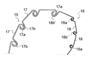
即ち、シャッター部15は、横に延びる各スラット17の上下に隣接するスラット17、17とそれぞれ枢動乃至屈曲可能に掛けとめられる係合部17a、17bが設けられて可撓性を有しており、強度との関係で所定の厚みに設定されている。
そこで、図3に示す天窓対応部16では、シャッター部15のスラット17より薄い、あるいは薄く短いスラット18を用いて、厚みの薄いシャッター構造としている。
なお、図中18a、18bはスラット18に可撓性を持たせるための一対の係合部であり、18b’は先端のスラット17の係合部17aに掛止めるための薄いスラット18の基端に形成された係合部である。
【0017】
あるいは、上記スラット17の左右両端部(ガイドレールに嵌合する部分)のみを用い、この独立した左右両端部を線材や板材で一体に連結したものであってもよい。
また、横だけでなく縦向きの線材や板材で連結してメッシュ状に形成してもよい。
【0018】
上記構成では、天窓対応部16にスラット相互の掛止めによる可撓構造を用いたが、それに替えて可撓性を有する線材や板材、布(シート)などの可撓性部材19を用いてもよい(図4参照)。
即ち、左右両端で長手方向に延びて、前記ガイドレール7に嵌合する一対の板材や線材の可撓性部材19をシャッター部15に連結し、該左右一対の板材や線材の間を横に延びる横架材(これも板材や線材でよい)で連結する構造でもよい。
この場合も、横向きの横架材を張設する構成に限らず縦横に連結したメッシュ状にしてもよい。
あるいは、これらに替えて布を用いたシートシャッターであってもよい。
【0019】
この天窓対応部16の上端は軸芯13に連結されており、また下端はシャッター部の上端に直接固着され、あるいは介設具20を介するなどして連結されている。
このように天窓対応部16は、ガード8を巻き取る際にシャッター部15を巻取収納部6の入口まで誘導しうるものであればよく、シャッター部15のようにカバーとしての保護機能を持たなくてもよい。
【0020】
次に、上記ガード8の引出し・巻取り方式は、手動式または自動式等を問わないが、本実施例では巻取収納部6が天窓10後方となり、オペレータの手が届かないので、自動式により引出し・巻取りが行えるように前記巻取り用の軸芯13を回転駆動させるモータ(油圧式や電動式など)を設けることが好ましい。
そして、運転室3内のスイッチ操作により、上記モータを正逆回転させてガード8を軸芯13から引出しまたは巻取ることができる。
【0021】
また、このガード8は、閉位置で固定されるように、ロック装置(図示省略)を設けてもよい。
このロック装置は、図示しないが、例えばシャッター式ガード8側にロック乃至ロック解除位置に変位可能なロック杆や爪を設け、固定側となるガイドレール7や、閉位置のシャッター部15の先端と接する位置のフレームに上記ロック杆や爪を受ける孔や受部を設けておき、ガード8を閉位置にして上記ロック杆や爪をロック方向に変位させて固定側の孔や受部に係合させてロックするなど、その他の公知のロック手段を用いることができる。
このロック手段では施錠装置を設けて上記係合を外せなくするようにしてもよい。
あるいはロック装置を設けずに、ガード8を閉位置に引き下ろすだけであってもよい。
【0022】
上記実施例では作業機械の一例として油圧ショベルを例示したが、この発明では前窓を有する運転室を備えた作業機械であれば、同様にガード装置を設けることができる。
また、天窓対応部の部材や可撓構造は上記実施例に限定されるものではなく、薄くまた軽量であればチェーン構造や公知の可撓性を有する構造や素材を用いることができる。
その他、要するにこの発明の要旨を変更しない範囲で種々設計変更しうること勿論である。
【0023】
【発明の効果】
以上、この発明の作用機械のガードにあっては、ガードにおける運転室の前窓を覆うシャッター部と、このシャッター部よりも巻き取り状態の体積が小さい可撓性を有する部材または構造体から成っているので、巻取収納部の容積を小さくして小型軽量化することができる。
またガードを軽量化しうるので、ガードの開閉操作を容易に行うことができる。
【図面の簡単な説明】
【図1】油圧ショベルのガード装置の一実施例を示す斜視図である。
【図2】ガード装置のガードを一部上げた状態の斜視図である。
【図3】ガード部を説明する部分断面図である。
【図4】別のガード部を説明する部分断面図である。
【図5】図1のガード装置を備えた油圧ショベルの全体を示す側面図である。
【符号の説明】
1 油圧ショベル
3 運転室
5 ガード装置
6 巻取収納部
7 ガイドレール
8 ガード
9 屋根部
10 天窓
11 前窓
12 前柱
15 シャッター部
16 天窓対応部
17 シャッタ部のスラット
18 天窓対応部のスラット
19 板材、線材、布などの可撓性部材[0001]
BACKGROUND OF THE INVENTION
The present invention relates to an improvement in a guard device including a vandalism guard that protects a front window of a cab of a work machine.
[0002]
[Prior art]
In a construction machine, particularly a hydraulic excavator that is often kept on the shoulder during construction, it is necessary to prevent mischief such as damaging the window glass of the cab by throwing stones or the like.
For the windows on the side surfaces other than the front window of the driver's cab, it can be handled by changing the material from glass to reinforced resin such as polycarbonate.
However, since the front window is wiped off with a wiper, a resin that is easily damaged cannot be used, and glass is used.
Therefore, in order to protect the front window made of glass in the cab, a guard made of an iron plate divided into a plurality of pieces that can be attached to the cab is provided.
[0003]
In this conventional structure, when the construction machine is held on the road shoulder or the like, the iron plate is fixed to the operator's cab with bolts or the like.
During the work of the construction machine, the iron plate is removed from the cab and stored in a storage box provided on the machine body.
However, in such a conventional structure, it is a heavy labor because it is attached and detached while holding a heavy iron plate.
Further, in the conventional structure, since it is necessary to store the iron plate in a storage box provided in the machine body, it may be difficult to store it if there is not enough space for storing the guard in the machine body of the construction machine. .
[0004]
Therefore, the above-mentioned drawback can be solved by installing a shutter type guard device instead of the iron plate, but when the winding storage part is arranged behind the skylight on the roof of the cab, the front upper visual field is Although it is not damaged, the total length of the shutter becomes long, so that the volume at the time of winding the shutter becomes large .
For this reason, the take-up storage unit has a large capacity, requires a large and robust structure, and the shutter itself is heavy.
[0005]
[Problems to be solved by the invention]
The present invention was devised in view of the above circumstances, and the skylight does not need to be made of glass as described above, and can be made of reinforced resin such as polycarbonate, so the portion corresponding to the skylight is a shutter. Since it does not have to be protected by a guard of the type, the guard is divided into a front window corresponding part and a skylight corresponding part, the former is a shutter structure, and the latter is a small and lightweight structure whose volume is smaller when winding than the shutter It is to provide a guard device for a work machine such as a construction machine.
[0006]
[Means for Solving the Problems]
In order to achieve the above object, in the invention of claim 1,
In the guard device that protects the front window of the cab of the work machine,
A winding storage unit installed behind the skylight provided on the roof of the cab, a pair of left and right guide rails provided from the installation location of the winding storage unit to the lower end position of the front window, and the winding storage unit It is provided with a guard that covers the front window by being drawn out along the guide rail.
The guard consists of a shutter part that covers the front window of the cab, and a skylight corresponding part provided above the shutter part,
Technical measures are taken such that the skylight-corresponding portion is made of a flexible member or structure that is thinner than the shutter portion and has a small volume during winding.
In the invention of
A technical means is adopted in which the skylight corresponding part of the guard is made of cloth or wire.
Furthermore, in the invention of
The guard's skylight-corresponding part has a technical means that it is formed in a mesh shape.
[0007]
DETAILED DESCRIPTION OF THE INVENTION
Hereinafter, a preferred embodiment in which the guard device for a work machine according to the present invention is applied to a hydraulic excavator as an example of a construction machine will be described with reference to the drawings.
The hydraulic excavator 1 has a known configuration of a
And in this
[0008]
The
[0009]
In the
[0010]
The
A winding
[0011]
In this embodiment, the
This urging spring for winding is an upward urging force that attempts to wind up the
[0012]
Next, a pair of left and
The
[0013]
The
And it can be displaced from the open position where the
[0014]
In the illustrated example, the
[0015]
The
The skylight
[0016]
That is, the
Therefore, the
In the figure, 18a and 18b are a pair of engaging portions for giving flexibility to the
[0017]
Alternatively, only the left and right ends of the slat 17 (parts fitted to the guide rail) may be used, and the independent left and right ends may be integrally connected with a wire or a plate.
Moreover, you may connect not only horizontally but with a longitudinally oriented wire and board | plate material, and you may form in mesh shape.
[0018]
In the above configuration, the skylight-corresponding
In other words, a pair of plate members or wire
In this case as well, the configuration is not limited to a configuration in which a horizontally oriented horizontal member is stretched, and a mesh shape that is vertically and horizontally connected may be used.
Alternatively, a sheet shutter using cloth instead of these may be used.
[0019]
The upper end of the
As described above, the
[0020]
Next, the drawing / winding method of the
The
[0021]
The
Although not shown, for example, the locking device is provided with a lock rod or a claw that can be displaced to a locked or unlocked position on the
This locking means may be provided with a locking device so that the engagement cannot be removed.
Alternatively, the
[0022]
In the above embodiment, a hydraulic excavator is illustrated as an example of the work machine. However, in the present invention, a guard device can be provided in the same manner as long as the work machine includes a cab having a front window.
Moreover, the member and flexible structure of a skylight corresponding | compatible part are not limited to the said Example, A chain structure and the structure and raw material which have well-known flexibility can be used if it is thin and lightweight.
In addition, it goes without saying that various design changes can be made without departing from the scope of the present invention.
[0023]
【The invention's effect】
As described above, the guard of the working machine according to the present invention includes the shutter portion that covers the front window of the cab in the guard, and the flexible member or structure that has a smaller volume in the wound state than the shutter portion. Therefore, the volume of the take-up storage unit can be reduced to reduce the size and weight.
Moreover, since the weight of the guard can be reduced, the opening / closing operation of the guard can be easily performed.
[Brief description of the drawings]
FIG. 1 is a perspective view showing an embodiment of a guard device for a hydraulic excavator.
FIG. 2 is a perspective view showing a state where a part of the guard of the guard device is raised.
FIG. 3 is a partial cross-sectional view illustrating a guard portion.
FIG. 4 is a partial cross-sectional view illustrating another guard portion.
5 is a side view showing the entirety of a hydraulic excavator provided with the guard device of FIG. 1. FIG.
[Explanation of symbols]
DESCRIPTION OF SYMBOLS 1
Claims (3)
運転室の屋根部に設けた天窓の後方に設置された巻取収納部と、該巻取収納部の設置個所から前窓下端位置まで設けられた左右一対のガイドレールと、前記巻取収納部に出入自在に設けられ、上記ガイドレールに沿って引き出されて前窓を覆うガードとからなっており、
上記ガードが、運転室の前窓を覆うシャッター部と、該シャッター部の上方に設けられた天窓対応部とからなり、
天窓対応部が、シャッター部よりも薄く巻き取り時の体積が小さい可撓性を有する部材または構造体からなることを特徴とする作業機械のガード装置。In the guard device that protects the front window of the cab of the work machine,
A winding storage unit installed behind the skylight provided on the roof of the cab, a pair of left and right guide rails provided from the installation location of the winding storage unit to the lower end position of the front window, and the winding storage unit It is provided with a guard that covers the front window by being drawn out along the guide rail.
The guard consists of a shutter part that covers the front window of the cab, and a skylight corresponding part provided above the shutter part,
A guard device for a work machine, wherein the skylight corresponding portion is made of a flexible member or structure that is thinner than the shutter portion and has a small volume when wound.
Priority Applications (1)
| Application Number | Priority Date | Filing Date | Title |
|---|---|---|---|
| JP2001295174A JP3760120B2 (en) | 2001-09-26 | 2001-09-26 | Guard device for work machine |
Applications Claiming Priority (1)
| Application Number | Priority Date | Filing Date | Title |
|---|---|---|---|
| JP2001295174A JP3760120B2 (en) | 2001-09-26 | 2001-09-26 | Guard device for work machine |
Publications (3)
| Publication Number | Publication Date |
|---|---|
| JP2003096826A JP2003096826A (en) | 2003-04-03 |
| JP2003096826A5 JP2003096826A5 (en) | 2004-09-30 |
| JP3760120B2 true JP3760120B2 (en) | 2006-03-29 |
Family
ID=19116651
Family Applications (1)
| Application Number | Title | Priority Date | Filing Date |
|---|---|---|---|
| JP2001295174A Expired - Fee Related JP3760120B2 (en) | 2001-09-26 | 2001-09-26 | Guard device for work machine |
Country Status (1)
| Country | Link |
|---|---|
| JP (1) | JP3760120B2 (en) |
Families Citing this family (6)
| Publication number | Priority date | Publication date | Assignee | Title |
|---|---|---|---|---|
| KR101363193B1 (en) | 2007-11-29 | 2014-02-14 | 두산인프라코어 주식회사 | Cabin protection device for construction vehicle |
| CN102704460B (en) * | 2012-06-14 | 2015-02-04 | 徐工集团工程机械股份有限公司 | Control cabin protection device and dynamic compaction machine |
| CN104649147A (en) * | 2015-01-26 | 2015-05-27 | 天津三宇车体制造有限公司 | Enhanced type wide-field cab |
| JP6845081B2 (en) | 2017-05-17 | 2021-03-17 | キャタピラー エス エー アール エル | Construction machinery cab |
| CN112249916A (en) * | 2020-10-27 | 2021-01-22 | 广东韶钢松山股份有限公司 | Protective device for crown block |
| CN115142506B (en) * | 2022-06-28 | 2023-06-13 | 三一重机有限公司 | Cab protection device and working machine |
-
2001
- 2001-09-26 JP JP2001295174A patent/JP3760120B2/en not_active Expired - Fee Related
Also Published As
| Publication number | Publication date |
|---|---|
| JP2003096826A (en) | 2003-04-03 |
Similar Documents
| Publication | Publication Date | Title |
|---|---|---|
| US7252321B2 (en) | Electric car sunshade | |
| US20010017194A1 (en) | Rear window roll-up blind | |
| KR20080082927A (en) | Automatically operable side window roller blind | |
| JP2008044605A (en) | Window shade driven by window lifter | |
| JP2008044606A (en) | Automatically accommodated manual window shade | |
| JP2008534358A (en) | Car cargo space cover | |
| JP3760120B2 (en) | Guard device for work machine | |
| KR20140061249A (en) | Rollo assembly and open roof construction provided therewith | |
| JP4133109B2 (en) | Shutter-type guard device for construction machinery | |
| US5129677A (en) | Protection system for a vehicle | |
| JP3689338B2 (en) | Guard device for construction machinery | |
| US7891729B2 (en) | Sliding roof structure and vehicle equipped with the same | |
| JPH04124514U (en) | Frame structure of sunroof device | |
| US20200290437A1 (en) | Shade apparatus for use with vehicles | |
| JP5591068B2 (en) | Sunshade device for vehicle | |
| JP2863488B2 (en) | Luggage carrier loading device | |
| JP2004517236A (en) | A system for driving and guiding sliding glazing in a door frame without a car window frame. | |
| JP3144571B2 (en) | Car door structure | |
| CN217477050U (en) | Movable window, cab and working machine | |
| KR200230350Y1 (en) | covering device of drivers seat for vehicle crane | |
| JP5002372B2 (en) | Sliding shutter driver housing and sliding shutter including the same | |
| KR100916207B1 (en) | Cargo screen | |
| FI128236B (en) | Roller blind | |
| JP5812033B2 (en) | Cab sunshade structure of construction machinery | |
| JP2008260353A (en) | Automobile door |
Legal Events
| Date | Code | Title | Description |
|---|---|---|---|
| A977 | Report on retrieval |
Free format text: JAPANESE INTERMEDIATE CODE: A971007 Effective date: 20051130 |
|
| TRDD | Decision of grant or rejection written | ||
| A01 | Written decision to grant a patent or to grant a registration (utility model) |
Free format text: JAPANESE INTERMEDIATE CODE: A01 Effective date: 20051213 |
|
| A61 | First payment of annual fees (during grant procedure) |
Free format text: JAPANESE INTERMEDIATE CODE: A61 Effective date: 20060106 |
|
| R150 | Certificate of patent or registration of utility model |
Free format text: JAPANESE INTERMEDIATE CODE: R150 |
|
| FPAY | Renewal fee payment (event date is renewal date of database) |
Free format text: PAYMENT UNTIL: 20090113 Year of fee payment: 3 |
|
| FPAY | Renewal fee payment (event date is renewal date of database) |
Free format text: PAYMENT UNTIL: 20100113 Year of fee payment: 4 |
|
| LAPS | Cancellation because of no payment of annual fees |