JP3757111B2 - Supported catalyst - Google Patents
Supported catalyst Download PDFInfo
- Publication number
- JP3757111B2 JP3757111B2 JP2000372601A JP2000372601A JP3757111B2 JP 3757111 B2 JP3757111 B2 JP 3757111B2 JP 2000372601 A JP2000372601 A JP 2000372601A JP 2000372601 A JP2000372601 A JP 2000372601A JP 3757111 B2 JP3757111 B2 JP 3757111B2
- Authority
- JP
- Japan
- Prior art keywords
- catalyst
- notches
- ring
- notch
- use according
- Prior art date
- Legal status (The legal status is an assumption and is not a legal conclusion. Google has not performed a legal analysis and makes no representation as to the accuracy of the status listed.)
- Expired - Fee Related
Links
- 239000003054 catalyst Substances 0.000 title claims abstract description 76
- QTBSBXVTEAMEQO-UHFFFAOYSA-N Acetic acid Chemical compound CC(O)=O QTBSBXVTEAMEQO-UHFFFAOYSA-N 0.000 claims description 27
- CTQNGGLPUBDAKN-UHFFFAOYSA-N O-Xylene Chemical group CC1=CC=CC=C1C CTQNGGLPUBDAKN-UHFFFAOYSA-N 0.000 claims description 14
- VXNZUUAINFGPBY-UHFFFAOYSA-N 1-Butene Chemical compound CCC=C VXNZUUAINFGPBY-UHFFFAOYSA-N 0.000 claims description 11
- IJDNQMDRQITEOD-UHFFFAOYSA-N n-butane Chemical compound CCCC IJDNQMDRQITEOD-UHFFFAOYSA-N 0.000 claims description 11
- 239000001273 butane Substances 0.000 claims description 9
- 239000000203 mixture Substances 0.000 claims description 9
- OFBQJSOFQDEBGM-UHFFFAOYSA-N n-pentane Natural products CCCCC OFBQJSOFQDEBGM-UHFFFAOYSA-N 0.000 claims description 9
- 230000003647 oxidation Effects 0.000 claims description 9
- 238000007254 oxidation reaction Methods 0.000 claims description 9
- IAQRGUVFOMOMEM-UHFFFAOYSA-N butene Natural products CC=CC IAQRGUVFOMOMEM-UHFFFAOYSA-N 0.000 claims description 7
- 229940078552 o-xylene Drugs 0.000 claims description 7
- VYPSYNLAJGMNEJ-UHFFFAOYSA-N Silicium dioxide Chemical compound O=[Si]=O VYPSYNLAJGMNEJ-UHFFFAOYSA-N 0.000 claims description 6
- UFWIBTONFRDIAS-UHFFFAOYSA-N Naphthalene Chemical compound C1=CC=CC2=CC=CC=C21 UFWIBTONFRDIAS-UHFFFAOYSA-N 0.000 claims description 4
- 230000001590 oxidative effect Effects 0.000 claims description 4
- LGRFSURHDFAFJT-UHFFFAOYSA-N Phthalic anhydride Natural products C1=CC=C2C(=O)OC(=O)C2=C1 LGRFSURHDFAFJT-UHFFFAOYSA-N 0.000 claims description 3
- 150000004645 aluminates Chemical class 0.000 claims description 3
- JHIWVOJDXOSYLW-UHFFFAOYSA-N butyl 2,2-difluorocyclopropane-1-carboxylate Chemical compound CCCCOC(=O)C1CC1(F)F JHIWVOJDXOSYLW-UHFFFAOYSA-N 0.000 claims description 3
- 229910052571 earthenware Inorganic materials 0.000 claims description 3
- 229930195733 hydrocarbon Natural products 0.000 claims description 3
- 150000002430 hydrocarbons Chemical class 0.000 claims description 3
- HBMJWWWQQXIZIP-UHFFFAOYSA-N silicon carbide Chemical compound [Si+]#[C-] HBMJWWWQQXIZIP-UHFFFAOYSA-N 0.000 claims description 3
- 229910010271 silicon carbide Inorganic materials 0.000 claims description 3
- 239000000377 silicon dioxide Substances 0.000 claims description 3
- 235000012239 silicon dioxide Nutrition 0.000 claims description 3
- 239000000126 substance Substances 0.000 claims description 3
- BPQQTUXANYXVAA-UHFFFAOYSA-N Orthosilicate Chemical compound [O-][Si]([O-])([O-])[O-] BPQQTUXANYXVAA-UHFFFAOYSA-N 0.000 claims description 2
- 239000000969 carrier Substances 0.000 claims description 2
- TWNQGVIAIRXVLR-UHFFFAOYSA-N oxo(oxoalumanyloxy)alumane Chemical compound O=[Al]O[Al]=O TWNQGVIAIRXVLR-UHFFFAOYSA-N 0.000 claims description 2
- 229910052573 porcelain Inorganic materials 0.000 claims description 2
- 239000012808 vapor phase Substances 0.000 claims 2
- 239000011149 active material Substances 0.000 claims 1
- 239000012071 phase Substances 0.000 claims 1
- 238000006243 chemical reaction Methods 0.000 description 24
- 239000013543 active substance Substances 0.000 description 10
- 238000004519 manufacturing process Methods 0.000 description 10
- 239000007789 gas Substances 0.000 description 9
- 230000000052 comparative effect Effects 0.000 description 8
- BDAGIHXWWSANSR-UHFFFAOYSA-N methanoic acid Natural products OC=O BDAGIHXWWSANSR-UHFFFAOYSA-N 0.000 description 6
- 238000012856 packing Methods 0.000 description 6
- 239000002253 acid Substances 0.000 description 5
- XLYOFNOQVPJJNP-UHFFFAOYSA-N water Substances O XLYOFNOQVPJJNP-UHFFFAOYSA-N 0.000 description 5
- 229910010413 TiO 2 Inorganic materials 0.000 description 4
- 239000006096 absorbing agent Substances 0.000 description 4
- 238000002474 experimental method Methods 0.000 description 4
- 238000011049 filling Methods 0.000 description 4
- 239000000463 material Substances 0.000 description 4
- 238000005259 measurement Methods 0.000 description 4
- 239000000725 suspension Substances 0.000 description 4
- OSWFIVFLDKOXQC-UHFFFAOYSA-N 4-(3-methoxyphenyl)aniline Chemical compound COC1=CC=CC(C=2C=CC(N)=CC=2)=C1 OSWFIVFLDKOXQC-UHFFFAOYSA-N 0.000 description 3
- UHOVQNZJYSORNB-UHFFFAOYSA-N Benzene Chemical compound C1=CC=CC=C1 UHOVQNZJYSORNB-UHFFFAOYSA-N 0.000 description 3
- WSFSSNUMVMOOMR-UHFFFAOYSA-N Formaldehyde Chemical compound O=C WSFSSNUMVMOOMR-UHFFFAOYSA-N 0.000 description 3
- OKKJLVBELUTLKV-UHFFFAOYSA-N Methanol Chemical compound OC OKKJLVBELUTLKV-UHFFFAOYSA-N 0.000 description 3
- 230000015572 biosynthetic process Effects 0.000 description 3
- 235000019253 formic acid Nutrition 0.000 description 3
- 238000000034 method Methods 0.000 description 3
- 239000012495 reaction gas Substances 0.000 description 3
- 150000003839 salts Chemical class 0.000 description 3
- 238000012360 testing method Methods 0.000 description 3
- HGINCPLSRVDWNT-UHFFFAOYSA-N Acrolein Chemical compound C=CC=O HGINCPLSRVDWNT-UHFFFAOYSA-N 0.000 description 2
- QQONPFPTGQHPMA-UHFFFAOYSA-N Propene Chemical compound CC=C QQONPFPTGQHPMA-UHFFFAOYSA-N 0.000 description 2
- 238000010521 absorption reaction Methods 0.000 description 2
- QVGXLLKOCUKJST-UHFFFAOYSA-N atomic oxygen Chemical compound [O] QVGXLLKOCUKJST-UHFFFAOYSA-N 0.000 description 2
- 239000011230 binding agent Substances 0.000 description 2
- ZCCIPPOKBCJFDN-UHFFFAOYSA-N calcium nitrate Chemical compound [Ca+2].[O-][N+]([O-])=O.[O-][N+]([O-])=O ZCCIPPOKBCJFDN-UHFFFAOYSA-N 0.000 description 2
- 239000012876 carrier material Substances 0.000 description 2
- 238000000576 coating method Methods 0.000 description 2
- 238000010586 diagram Methods 0.000 description 2
- 230000000694 effects Effects 0.000 description 2
- 238000001125 extrusion Methods 0.000 description 2
- FPYJFEHAWHCUMM-UHFFFAOYSA-N maleic anhydride Chemical compound O=C1OC(=O)C=C1 FPYJFEHAWHCUMM-UHFFFAOYSA-N 0.000 description 2
- 238000000465 moulding Methods 0.000 description 2
- 239000001301 oxygen Substances 0.000 description 2
- 229910052760 oxygen Inorganic materials 0.000 description 2
- 239000000843 powder Substances 0.000 description 2
- 239000000047 product Substances 0.000 description 2
- 239000003507 refrigerant Substances 0.000 description 2
- 238000000926 separation method Methods 0.000 description 2
- LPXPTNMVRIOKMN-UHFFFAOYSA-M sodium nitrite Chemical compound [Na+].[O-]N=O LPXPTNMVRIOKMN-UHFFFAOYSA-M 0.000 description 2
- 238000003786 synthesis reaction Methods 0.000 description 2
- 239000010936 titanium Substances 0.000 description 2
- SMZOUWXMTYCWNB-UHFFFAOYSA-N 2-(2-methoxy-5-methylphenyl)ethanamine Chemical compound COC1=CC=C(C)C=C1CCN SMZOUWXMTYCWNB-UHFFFAOYSA-N 0.000 description 1
- NIXOWILDQLNWCW-UHFFFAOYSA-N 2-Propenoic acid Natural products OC(=O)C=C NIXOWILDQLNWCW-UHFFFAOYSA-N 0.000 description 1
- OTMSDBZUPAUEDD-UHFFFAOYSA-N Ethane Chemical compound CC OTMSDBZUPAUEDD-UHFFFAOYSA-N 0.000 description 1
- ZOKXTWBITQBERF-UHFFFAOYSA-N Molybdenum Chemical compound [Mo] ZOKXTWBITQBERF-UHFFFAOYSA-N 0.000 description 1
- GWEVSGVZZGPLCZ-UHFFFAOYSA-N Titan oxide Chemical compound O=[Ti]=O GWEVSGVZZGPLCZ-UHFFFAOYSA-N 0.000 description 1
- RTAQQCXQSZGOHL-UHFFFAOYSA-N Titanium Chemical compound [Ti] RTAQQCXQSZGOHL-UHFFFAOYSA-N 0.000 description 1
- XTXRWKRVRITETP-UHFFFAOYSA-N Vinyl acetate Chemical compound CC(=O)OC=C XTXRWKRVRITETP-UHFFFAOYSA-N 0.000 description 1
- 239000000654 additive Substances 0.000 description 1
- 150000001299 aldehydes Chemical class 0.000 description 1
- 150000001339 alkali metal compounds Chemical class 0.000 description 1
- 229910000410 antimony oxide Inorganic materials 0.000 description 1
- 238000009530 blood pressure measurement Methods 0.000 description 1
- MTAZNLWOLGHBHU-UHFFFAOYSA-N butadiene-styrene rubber Chemical compound C=CC=C.C=CC1=CC=CC=C1 MTAZNLWOLGHBHU-UHFFFAOYSA-N 0.000 description 1
- 229910052792 caesium Inorganic materials 0.000 description 1
- TVFDJXOCXUVLDH-UHFFFAOYSA-N caesium atom Chemical compound [Cs] TVFDJXOCXUVLDH-UHFFFAOYSA-N 0.000 description 1
- 150000001244 carboxylic acid anhydrides Chemical class 0.000 description 1
- 150000001735 carboxylic acids Chemical class 0.000 description 1
- 230000003197 catalytic effect Effects 0.000 description 1
- 239000007795 chemical reaction product Substances 0.000 description 1
- 239000011248 coating agent Substances 0.000 description 1
- 238000001816 cooling Methods 0.000 description 1
- 229920001577 copolymer Polymers 0.000 description 1
- 238000000354 decomposition reaction Methods 0.000 description 1
- 235000011180 diphosphates Nutrition 0.000 description 1
- 239000006185 dispersion Substances 0.000 description 1
- GLVVKKSPKXTQRB-UHFFFAOYSA-N ethenyl dodecanoate Chemical compound CCCCCCCCCCCC(=O)OC=C GLVVKKSPKXTQRB-UHFFFAOYSA-N 0.000 description 1
- 230000005496 eutectics Effects 0.000 description 1
- 238000011156 evaluation Methods 0.000 description 1
- 239000013529 heat transfer fluid Substances 0.000 description 1
- 239000007970 homogeneous dispersion Substances 0.000 description 1
- 239000007788 liquid Substances 0.000 description 1
- 239000000391 magnesium silicate Substances 0.000 description 1
- 229910052919 magnesium silicate Inorganic materials 0.000 description 1
- 235000019792 magnesium silicate Nutrition 0.000 description 1
- ZADYMNAVLSWLEQ-UHFFFAOYSA-N magnesium;oxygen(2-);silicon(4+) Chemical compound [O-2].[O-2].[O-2].[Mg+2].[Si+4] ZADYMNAVLSWLEQ-UHFFFAOYSA-N 0.000 description 1
- 229910052751 metal Inorganic materials 0.000 description 1
- 239000002184 metal Substances 0.000 description 1
- 229910001092 metal group alloy Inorganic materials 0.000 description 1
- 239000011733 molybdenum Substances 0.000 description 1
- 229910000476 molybdenum oxide Inorganic materials 0.000 description 1
- 239000003960 organic solvent Substances 0.000 description 1
- VTRUBDSFZJNXHI-UHFFFAOYSA-N oxoantimony Chemical class [Sb]=O VTRUBDSFZJNXHI-UHFFFAOYSA-N 0.000 description 1
- 230000000737 periodic effect Effects 0.000 description 1
- 230000000704 physical effect Effects 0.000 description 1
- 238000002360 preparation method Methods 0.000 description 1
- 235000010288 sodium nitrite Nutrition 0.000 description 1
- 239000007787 solid Substances 0.000 description 1
- 239000007858 starting material Substances 0.000 description 1
- OGIDPMRJRNCKJF-UHFFFAOYSA-N titanium oxide Inorganic materials [Ti]=O OGIDPMRJRNCKJF-UHFFFAOYSA-N 0.000 description 1
- 230000007704 transition Effects 0.000 description 1
- LEONUFNNVUYDNQ-UHFFFAOYSA-N vanadium atom Chemical compound [V] LEONUFNNVUYDNQ-UHFFFAOYSA-N 0.000 description 1
- 229910001935 vanadium oxide Inorganic materials 0.000 description 1
- -1 vanadyl pyrophosphate Chemical compound 0.000 description 1
Images

Classifications
-
- C—CHEMISTRY; METALLURGY
- C07—ORGANIC CHEMISTRY
- C07C—ACYCLIC OR CARBOCYCLIC COMPOUNDS
- C07C51/00—Preparation of carboxylic acids or their salts, halides or anhydrides
- C07C51/16—Preparation of carboxylic acids or their salts, halides or anhydrides by oxidation
- C07C51/21—Preparation of carboxylic acids or their salts, halides or anhydrides by oxidation with molecular oxygen
- C07C51/25—Preparation of carboxylic acids or their salts, halides or anhydrides by oxidation with molecular oxygen of unsaturated compounds containing no six-membered aromatic ring
-
- B—PERFORMING OPERATIONS; TRANSPORTING
- B01—PHYSICAL OR CHEMICAL PROCESSES OR APPARATUS IN GENERAL
- B01J—CHEMICAL OR PHYSICAL PROCESSES, e.g. CATALYSIS OR COLLOID CHEMISTRY; THEIR RELEVANT APPARATUS
- B01J23/00—Catalysts comprising metals or metal oxides or hydroxides, not provided for in group B01J21/00
- B01J23/16—Catalysts comprising metals or metal oxides or hydroxides, not provided for in group B01J21/00 of arsenic, antimony, bismuth, vanadium, niobium, tantalum, polonium, chromium, molybdenum, tungsten, manganese, technetium or rhenium
- B01J23/20—Vanadium, niobium or tantalum
- B01J23/22—Vanadium
-
- B01J35/50—
-
- C—CHEMISTRY; METALLURGY
- C07—ORGANIC CHEMISTRY
- C07C—ACYCLIC OR CARBOCYCLIC COMPOUNDS
- C07C51/00—Preparation of carboxylic acids or their salts, halides or anhydrides
- C07C51/16—Preparation of carboxylic acids or their salts, halides or anhydrides by oxidation
- C07C51/21—Preparation of carboxylic acids or their salts, halides or anhydrides by oxidation with molecular oxygen
- C07C51/215—Preparation of carboxylic acids or their salts, halides or anhydrides by oxidation with molecular oxygen of saturated hydrocarbyl groups
-
- C—CHEMISTRY; METALLURGY
- C07—ORGANIC CHEMISTRY
- C07C—ACYCLIC OR CARBOCYCLIC COMPOUNDS
- C07C51/00—Preparation of carboxylic acids or their salts, halides or anhydrides
- C07C51/16—Preparation of carboxylic acids or their salts, halides or anhydrides by oxidation
- C07C51/21—Preparation of carboxylic acids or their salts, halides or anhydrides by oxidation with molecular oxygen
- C07C51/255—Preparation of carboxylic acids or their salts, halides or anhydrides by oxidation with molecular oxygen of compounds containing six-membered aromatic rings without ring-splitting
- C07C51/265—Preparation of carboxylic acids or their salts, halides or anhydrides by oxidation with molecular oxygen of compounds containing six-membered aromatic rings without ring-splitting having alkyl side chains which are oxidised to carboxyl groups
-
- B—PERFORMING OPERATIONS; TRANSPORTING
- B01—PHYSICAL OR CHEMICAL PROCESSES OR APPARATUS IN GENERAL
- B01J—CHEMICAL OR PHYSICAL PROCESSES, e.g. CATALYSIS OR COLLOID CHEMISTRY; THEIR RELEVANT APPARATUS
- B01J21/00—Catalysts comprising the elements, oxides, or hydroxides of magnesium, boron, aluminium, carbon, silicon, titanium, zirconium, or hafnium
- B01J21/06—Silicon, titanium, zirconium or hafnium; Oxides or hydroxides thereof
- B01J21/063—Titanium; Oxides or hydroxides thereof
-
- B—PERFORMING OPERATIONS; TRANSPORTING
- B01—PHYSICAL OR CHEMICAL PROCESSES OR APPARATUS IN GENERAL
- B01J—CHEMICAL OR PHYSICAL PROCESSES, e.g. CATALYSIS OR COLLOID CHEMISTRY; THEIR RELEVANT APPARATUS
- B01J23/00—Catalysts comprising metals or metal oxides or hydroxides, not provided for in group B01J21/00
- B01J23/16—Catalysts comprising metals or metal oxides or hydroxides, not provided for in group B01J21/00 of arsenic, antimony, bismuth, vanadium, niobium, tantalum, polonium, chromium, molybdenum, tungsten, manganese, technetium or rhenium
- B01J23/24—Chromium, molybdenum or tungsten
- B01J23/28—Molybdenum
-
- Y—GENERAL TAGGING OF NEW TECHNOLOGICAL DEVELOPMENTS; GENERAL TAGGING OF CROSS-SECTIONAL TECHNOLOGIES SPANNING OVER SEVERAL SECTIONS OF THE IPC; TECHNICAL SUBJECTS COVERED BY FORMER USPC CROSS-REFERENCE ART COLLECTIONS [XRACs] AND DIGESTS
- Y02—TECHNOLOGIES OR APPLICATIONS FOR MITIGATION OR ADAPTATION AGAINST CLIMATE CHANGE
- Y02P—CLIMATE CHANGE MITIGATION TECHNOLOGIES IN THE PRODUCTION OR PROCESSING OF GOODS
- Y02P20/00—Technologies relating to chemical industry
- Y02P20/50—Improvements relating to the production of bulk chemicals
- Y02P20/582—Recycling of unreacted starting or intermediate materials
-
- Y—GENERAL TAGGING OF NEW TECHNOLOGICAL DEVELOPMENTS; GENERAL TAGGING OF CROSS-SECTIONAL TECHNOLOGIES SPANNING OVER SEVERAL SECTIONS OF THE IPC; TECHNICAL SUBJECTS COVERED BY FORMER USPC CROSS-REFERENCE ART COLLECTIONS [XRACs] AND DIGESTS
- Y10—TECHNICAL SUBJECTS COVERED BY FORMER USPC
- Y10S—TECHNICAL SUBJECTS COVERED BY FORMER USPC CROSS-REFERENCE ART COLLECTIONS [XRACs] AND DIGESTS
- Y10S261/00—Gas and liquid contact apparatus
- Y10S261/72—Packing elements
Abstract
Description
【0001】
【発明の属する技術分野】
本発明は、担体触媒及びその炭化水素の気相酸化における使用に関する。
【0002】
炭化水素を相応する酸化生成物、例えばカルボン酸、無水カルボン酸又はアルデヒドに気相酸化するための担体触媒は従来公知である。このような触媒のための典型的適用は、o−キシレン又はナフタリンからの無水フタル酸、ベンゼン又はブタンからの無水マレイン酸、メタノールからのホルムアルデヒド、プロペンからのアクリル酸又はアクロレインの製造である。もちろん、担体触媒を用いてエタン又はブタン並びにブタン/ブテン混合物を酸化させることによる酢酸の製造も記載されている。これらのすべの製造方法にとって共通であるのは、反応が強度に発熱的に進行することである。この理由から、このような殆ど全ての方法はいわゆる管形反応器内で実施される。この場合、管に触媒が充填され、発生する反応熱の導出(冷却)は、通常反応器内の反応管を包囲する塩溶融物を介して行われる。冷却は、温度範囲に依存して選択的に蒸気、過熱水又は別の伝熱流体で行うこともできる。
【0003】
使用される触媒は、主として、一般に実際に触媒活性物質が施された例えばリング形又は球形の不活性担体からなる担体触媒である。このような触媒活性物質は、例えばPSA触媒及び酢酸触媒の場合には主としてアナタス形のTiO2及びV2O5からなる。この場合、活性の制御を改良するため及び選択性を改良するために、しばしば付加的になお活性化する或いはまた緩衝する添加物、例えば周期系の副族の元素の酸化物、アルカリ金属化合物、及び/又は少量でドーピング物質としてのプロモータが触媒活性物質に配合される。MSAを製造するための触媒においては、触媒活性物質は例えばバナジルピロホスフェートからなる。
【0004】
担体触媒を製造する際には、一般に触媒粉末と液体(水、有機溶剤)からなる懸濁液或いはまた個々の触媒成分の溶液又は懸濁液が、場合により担体上での活性成分の付着を改良するための結合剤を添加して、担体成形体に噴霧される。
【0005】
EP−B714700(US−A5,677,261)から、湿った担体成形体に乾燥粉末を塗布することも公知である。
【0006】
担体成形体としては、通常規則的に成形された、機械的に安定な成形体、例えば球、リング、半リング、鞍が使用される。この場合、担体成形体の大きさは、主として反応器の寸法、就中個々の反応管の内径により決まる。この場合、担体材料としては、ステアタイト、デュラナイト(Duranit)、陶器、二酸化ケイ素、炭化ケイ素、アルミン酸塩、金属、及び金属合金が使用される。
【0007】
担体形及びその寸法の選択の際には、特にそれと結び付いた圧力損失が重要な役割を演じる。触媒ばら物の少ない圧力損失は、例えばブローエネルギーの場合には、著しいエネルギー倹約を意味することがある。
【0008】
もう1つの基準は、担体材料をできるだけ廉価に製造することができることにある。この場合、工業においてはリング及び球が普及しており、この場合リングの際に存在する僅かな圧力損失に基づきリング状担体がますます使用される。
【0009】
過去には、リング形を変更することにより、最適な圧力損失(即ちできるだけ低い圧力損失)を示しかつその際できるだけ多くの活性物質を担持し、しかし別の性能データ、例えば選択性、安定性、生産性等を劣化しない担体材料を見出す実験が多数行われた。
【0010】
DE−A3445289(US−A4,656,157)には、例えば、“普通のリング”とは、その端面が丸み付けられていることにより区別されるリング担体が記載されている。このリング担体は、反応管の一層均一な充填、ひいては均等な反応進行を可能するという。圧力発生に関しては、何ら記載されていない。
【0011】
充実の幾何学的形からなり、その際この外側表面に少なくとも1つの中空室が配置されている、無水マレイン酸を製造するためのフルコンタクト触媒(Vollkontakt-Katalysator)が記載されている。この場合、実施例には専ら、中空室が外側表面に配置されておりかつ端面には配置されていない形が記載されている。この形の目的は、フルコンタクト触媒のできるだけ大きな表面積を得ることである。この場合、示された形は技術的に大きな消費及び高いコストをもって実現されるに過ぎない。
【0012】
EP−A220933から、接触法で使用するための“四葉タイプ”の形を有するフルコンタクト触媒が公知である。この場合、この形は触媒材料の押出により達成される。その特殊な形により、該触媒は破壊強度及び圧力発生に関して良好な物理的特性を有する。
【0013】
GB−A2193907には、円筒形の触媒が記載されており、該触媒の外套は長手方向にリブを備え、該リブは、個々の触媒体が噛み合うことができないように寸法が決定されかつ配置されている。
【0014】
US−A4,328,130には、同様に、円筒体の長手方向に複数の通路及びリブが貫通した触媒形が記載されており、この場合には噛み合いを回避するために、切欠はリブよりも幅が狭い。
【0015】
EP−A004079(US−A4,370,492及びUS−A4,370,261)から、星形横断面を有するストランド切片又はリブが設けられたストランドである触媒形が公知である。
【0016】
US−A3,966,644には、互いに平行に接合された円筒体の形の押出されたストランド成形品からなる触媒形を記載されている。
【0017】
従来の技術に記載された、低下せしめられた圧力発生を有する触媒担体のための形は、全て極めて複雑な形を有する。この場合、製造は大抵高いコストと結び付き、ひいては工業的規模では不経済である。
【0018】
就中押出成形により得られる前記の複雑な形の多くは、その表面の理由から触媒活性物質での被覆のためには不適当であり、かつひいてはフルコンタクトとしてのみ使用することができるに過ぎない。
【0019】
【発明が解決しようとする課題】
従って、本発明の課題は、一面では反応器内で従来のリング又は球よりも少ない圧力発生を示し、しかし他面ではできるだけ簡単であるが、しかし高幾何学的(hochgeometrisch)、ひいては被覆可能な表面を有する触媒担体を提供することであった。さらに、これらの担体成形体は、簡単かつ廉価に製造可能であるべきでありかつ該担体成形体を問題なく既存の酸化装置及び方法で使用することができるために、幾何学的形状が工業的に使用される担体から著しくはずれているべきでない。さらに、開発すべき担体触媒は従来の技術から公知のものと同様に良好な安定性を有し、公知の充填機械で反応管に充填されかつ活性物質で被覆する際に均一な層厚さを可能にすべきである。
【0020】
【課題を解決するための手段】
前記課題は、本発明により、リングの形の不活性担体成形体上の活性物質からなる担体触媒により解決され、該担体触媒は、リングがリングの上方及び/又は下方平坦面に単数又は複数のノッチを有することを特徴とする。
【0021】
本発明による触媒の平坦面上のノッチの数は、相応する反応の要求及びリング担体の寸法により決まる。この場合、リングの少なくとも1つの平坦面は、少なくとも1つのノッチを備えている。リングの両者の平坦面のそれぞれが単数又は複数のノッチを備えている担体成形体が有利である。それぞれの平坦面に2〜8個のノッチ、特に2〜4個のノッチを有する触媒が有利である。
【0022】
使用されるリングの大きさは、まず第一に反応器の要求、即ち大きさにより決まる。その際、担体直径は、反応管の内径の1/2〜1/10、有利には1/3〜1/5であるべきである。材料としては、例えばステアタイト、デュラナイト、炭化ケイ素、陶器、磁器、二酸化ケイ素、ケイ酸塩、酸化アルミニウム、アルミン酸塩又はこれらの物質の混合物が適当である。これらは密に焼結されていてもよく、或いはまた多孔質構造を有していてもよい。高さ4〜10mm、外径6〜10mm及び壁厚さ1〜2mmを有するステアタイト(密に焼結されたケイ酸マグネシウム)を使用するのが有利である。
【0023】
それぞれの面上の本発明によるノッチは、規則的に又は不規則的に分配されて存在することができる。この場合、リングの平坦面上のノッチの配置は、常に“互い違いに”存在するように選択するのが有利である。従って、例えば各々の平坦面にそれぞれ2つのノッチを有する本発明による触媒においては、向かい合った面にノッチが90゜ずらして配置されている。ノッチの形は、半円、矩形、台形状又はV字形状であってよい。
【0024】
この場合、ノッチを形成する場合には、個々のノッチがリング厚さより幾分か小さいか又は明らかに大きい場合が有利である。このようにして、殊に被覆工程を困難にする噛み合いを回避することができる。この場合、ノッチの深さ及び幅は担体の機械的安定性により決まる。ノッチの寸法は、少なくとも、ノッチが活性物質で被覆する際に閉塞されないような大きさであるべきである。最大のノッチ深さ及びまたその幅は、使用段階(反応器充填)におけるような別の製造工程で触媒の分解を生じるべきでないことにより制限される。
【0025】
上方及び下方のノッチが設けられている場合、リング成形体の高さの1/3〜1/2の深さを有するノッチが有利である。触媒の片面のみに本発明によるノッチが設けられている場合には、ノッチの深さはリング成形体の半分の深さより大きくてもよい。最終的には、最大ノッチ深さは担体の後に残る安定性に依存する。
【0026】
リングの上方及び下方端面にそれぞれ2つのノッチを設けることにより、圧力損失を約30%減少させ、それにより被覆可能な表面の問題になるほどの損失は生じない。
【0027】
驚異的にも、ブタン、ブテン及びそれらの混合物の酢酸への気相酸化の実施例で、本発明による触媒が反応器内での減少された圧力発生の他に付加的に4%の出発物質の反応の際の明らかな選択性向上を有することを立証することができた。さらにまた、主反応帯域内でのホットポット(Hot-Spots)の形成が、o−キシレンのPSAへの酸化の例が示すように明白に軽減されることを観察することができた。
【0028】
【実施例】
以下の実施例により、本発明を詳細に説明する。
【0029】
実施例1:(形状例)
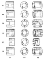
図1a〜fは、ノッチの種々異なる数及び配置を有する本発明による触媒の若干の形状例を示す。この場合、触媒成形体は、それぞれ側面図(1)、平面図(2)及び斜視図(3)で示されている。
【0030】
a)上面及び下面にそれぞれ2つのノッチ、互いに90゜ずらされており、ノッチ深さ:リング高さの1/3、ノッチ幅:リング厚さよりも小さい。
【0031】
b)上面及び下面にそれぞれ2つのノッチ、互いに90゜ずらされており、ノッチ深さ:リング高さの1/2、ノッチ幅:リング厚さよりも小さい。
【0032】
c)上面及び下面にそれぞれ4つのノッチ、互いに45゜ずらされており、ノッチ深さ:リング高さの1/3、ノッチ幅:リング厚さよりも小さい。
【0033】
d)上面及び下面にそれぞれ2つのノッチ、互いに90゜ずらされており、ノッチ深さ:リング高さの1/3、ノッチ幅:リング厚さよりも大きい。
【0034】
e)一方の面に2つのノッチ、ノッチ深さ:リング高さの1/3、ノッチ幅:リング厚さよりも小さい。
【0035】
f)上面及び下面にそれぞれ1つのノッチ、互いに180゜ずらされており、ノッチ深:さリング高さの1/3、ノッチ幅:リング厚さよりも小さい。
【0036】
図2a〜cは、ノッチの種々異なる幾何学的形状を有する本発明による触媒の若干の形状例を示す。この場合、触媒成形体は、それぞれ側面図(1)、平面図(2)及び斜視図(3)で示されている。
【0037】
a)U字形ノッチ
b)V字形ノッチ
c)台形状ノッチ。
【0038】
実施例2:(圧力損失測定)
管長348cm、内径25mm、圧力調節器(0〜7.5バール)、ロータメータ(0〜5Nm3/h)、進入圧室及びせき止め圧マノメータを有する測定装置に、触媒リングを充填した。充填高さはリングA,B,C及びDに関しては280cm並びにリングE及びFに関しては72cmであった。
【0039】
せき止め圧測定のために、回路網圧搾空気(6バール)を圧力調節器で2.5バールに低下させた。ロータメータで、1.5バールの進入圧を有する必要な空気量(3及び4Nm3/h)を調節した。次いで、該圧力をせき止め圧マノメータで読み取ることができた。測定は室温で行った。
【0040】
この場合、測定を被覆した触媒リング(C,D)及び被覆しない触媒リング(A,B)で実施した。被覆リングは、V2O5/TiO2からなる触媒物質それぞれ8質量%で被覆した。それぞれ上面に2つのノッチ及び下面に2つのノッチを有するノッチを設けたリング(A,C)を使用した。この場合、ノッチは互いに90゜ずらされていた。該リングは7×7×4mm(外径×高さ×内径)の寸法を有し、ノッチ幅は1.4mm及びノッチ深さは2mmであった。比較のために、ノッチを備えていない、7×7×4mmの寸法を有するリングを測定した。
【0041】
付加的に、7×4×4mmの寸法を有する小さいリング(E)を測定した。これらのリングは、両面に2つの矩形のノッチを備えていた。この場合、ノッチは互いに90゜ずらされておりかつそれぞれ深さ2mm及び幅1.4mmを有していた。これに対する比較として、同じ寸法を有するが、但しノッチを有しないリング(F)を測定した。これらの測定から得られた結果は、第1表及び第2表に示されている。
【0042】
【表1】

【表2】
実験結果の表にした評価により、本発明による触媒が従来のノッチが設けられていない触媒に比して低い圧力損失を惹起することは明白である。この場合、7×7×4mmの大きさを有する本発明による触媒は、約20%低い圧力損失を示し、7×4×4mmを有するより小さいリングの場合にはこの効果はその上34%まで増大する。
【0045】
実施例3:(無水フタル酸を合成するための本発明による触媒の製造)
触媒を製造するために、V2O511.3g、TiO2(BET8m2/g)70.8g、TiO2(BET200m2/g)17.7g及びセシウム(CsCO3として)0.2gを脱イオン水400ml中に懸濁させかつ均質な分散を達成するために18時間攪拌した。この懸濁液に、ビニルアセテート及びビニルラウレートのコポリマーからなる有機バインダー1.5gを50質量%の水性分散液の形で加えた。引き続き、得られた懸濁液をそれぞれ上面に2つのノッチ及び下面に2つのノッチを有するステアタイトリング1203gに噴霧しかつ乾燥した。この場合、ノッチは90゜互いにずらされていた。該リングは7×7×4mmの寸法を有し、ノッチ幅は1.4mmでありかつノッチ深さは2mmであった。
【0046】
比較例1:(ノッチが設けられていないリング上の例3からの触媒)
大きさ7×7×4mmのノッチが設けられていないステアタイトに塗布した点を別にして、実施例3に類似して触媒を製造した。
【0047】
実施例4:(酢酸を合成するための本発明による触媒の製造)
触媒の製造を、DE−A19649426に類似して行った。活性物質は、実験式TiaVbMocSbdO(a:91;b:7;c:1;d:3;e:207)及び担体の質量に対して14.4質量%プラス1.6質量%の割合のチタン、バナジウム、モリブデン及びアンチモンの酸化物からなる。これらの活性物質をそれぞれ上面に2つのノッチ及び下面に2つのノッチを有するステアタイトリングに塗布しかつ乾燥した。この場合、ノッチは90゜互いにずらされていた。該リングは7×7×4mmの寸法を有し、ノッチ幅は1.4mmでありかつノッチ深さは2mmであった。
【0048】
比較例2:(ノッチが設けられていないリング上の例4からの触媒)
7×7×4mm(外径×内径×高さ)の寸法を有するノッチが設けられていないステアタイトに塗布した点を別にして、実施例4に類似して触媒を製造した。
【0049】
実施例5:(o−キシレン酸化の例での実施例3及び比較例1からの触媒の試験)
該試験は、長さ330cm及び管内径25mmを有する管形反応器内で実施した。該管を循環塩浴(硝酸カルシウム及び亜硝酸ナトリウムからなる共融溶融物)で温度調節した。反応器に実施例3からの本発明による触媒並びに比較例1からの触媒を充填した。触媒充填高さは、両者の実験において280cmであった。塩浴温度は365℃であった。充填後に、この反応器に空気/o−キシレン混合物4Nm3を貫流させた。この際、o−キシレン濃度は60g/空気Nm3でありかつ空気/o−キシレン混合物を反応器に流入する前に180℃に予熱した。反応器に心合わせして、管内の温度推移の測定が可能である熱電対を設置した。
【0050】
反応器を出る反応ガスを、PSAのような反応生成物を分離するために、昇華器(Desublimator)を貫流させた。
【0051】
実験結果は、以下の第3表に示されている。
【0052】
【表3】
第3表に記載の結果から、本発明による、ノッチを設けた触媒が明らかい低い圧力損失を示すことが明白である。生成物収率は、本発明による触媒においては同様に良好である。反応管内の最高温度(ホットスポット)の比較により、本発明による触媒が意想外にも付加的に低いホットスポット有することが認識される。
【0054】
実施例6:(ブタン/ブテン混合物を酸化して酢酸にする例での実施例4及び比較例2からの触媒の試験)
実施例4からの本発明による触媒を、反応管内径25mmを有する循環ガス内に充填高さ6000mmで充填しかつDE−A19910866に基づきブテン/ブタン混合物の酸化の例で試験した。反応ガスとしては、酸素320g/h、1−ブテン130g/h及びn−ブタン56g/hを供給した。循環ガス流量は、反応器が安定状態で循環ガス流量12780g/hを達成するように調節した。反応器を圧力11×105Pa及び冷媒温度187℃で運転した。
【0055】
反応ガスからの酸分離は、構造化した充填物、内径43mm及び充填高さ3240mmを有する吸収器内で吸収器の頂部温度130℃で水1000g/hで吸収させることにより実施した。この条件下で、ブテン反応率99.8%及びブタン反応率83.1%が達成された。
【0056】
全C4反応率に関する酢酸選択性は73モル%であり、全C4反応率に関する蟻酸選択性は9モル%であった。粗酸濃度は24質量%であった。
【0057】
別の実験で、上記仕様に類似して比較例2からの比較触媒を用いて実験を行った(酸素333g/h、1−ブテン130g/h及びn−ブタン60g/h)。。循環ガス流量は、反応器が安定状態で循環ガス流量12520g/hを達成するように調節した。反応器を圧力11×105Pa及び冷媒温度191℃で運転した。
【0058】
反応ガスからの酸分離は、構造化した充填物、内径43mm及び充填高さ3240mmを有する吸収器内で吸収器の頂部温度130℃で水1000g/h(頂部からの放出)で吸収させることにより実施した。この条件下で、ブテン反応率99.8%及びブタン反応率83.8%が達成された。
【0059】
全C4反応率に関する酢酸選択性は70モル%であり、全C4反応率に関する蟻酸選択性は8モル%であった。粗酸濃度は23質量%であった。
【0060】
この結果は、本発明による、ノッチが設けられた触媒は、意想外にも殆ど同じ実験条件で3モル%高い酢酸選択性並びに1%高い蟻酸選択性を生じたことを示す。このことから、この反応の4%高い全酸選択性を生じる。同時に、触媒充填の圧力損失は比較触媒よりも約20%低かった。この事実に基づき、このような反応において法外なエネルギー倹約が生じる。
【図面の簡単な説明】
【図1】図1a〜fは、ノッチの種々異なる数及び配置を有する本発明による触媒の若干の形状例を示す図であり、かつ(1)は触媒成形体の側面図、(2)は平面図及び(3)は斜視図である。
【図2】図2a〜cは、ノッチの種々異なる幾何学的形状を有する本発明による触媒の若干の形状例を示す図であり、(1)は触媒成形体の側面図、(2)は平面図及び(3)は斜視図である。[0001]
BACKGROUND OF THE INVENTION
The present invention relates to a supported catalyst and its use in the gas phase oxidation of hydrocarbons.
[0002]
Supported catalysts for the gas phase oxidation of hydrocarbons to the corresponding oxidation products such as carboxylic acids, carboxylic anhydrides or aldehydes are known in the art. Typical applications for such catalysts are the production of phthalic anhydride from o-xylene or naphthalene, maleic anhydride from benzene or butane, formaldehyde from methanol, acrylic acid or acrolein from propene. Of course, the production of acetic acid by oxidizing ethane or butane as well as butane / butene mixtures using supported catalysts is also described. Common to all these production methods is that the reaction proceeds strongly exothermically. For this reason, almost all such processes are carried out in so-called tubular reactors. In this case, the tube is filled with a catalyst, and the generated reaction heat is derivatized (cooled) usually via a salt melt surrounding the reaction tube in the reactor. Cooling can also be done selectively with steam, superheated water or another heat transfer fluid, depending on the temperature range.
[0003]
The catalyst used is mainly a supported catalyst consisting of an inert support, for example in the form of a ring or sphere, generally provided with a catalytically active substance. Such catalytically active substances consist mainly of anatase TiO 2 and V 2 O 5 in the case of PSA catalysts and acetic acid catalysts, for example. In this case, in order to improve the control of activity and to improve the selectivity, additives which are often additionally activated or also buffered, such as oxides of elements of the subgroups of the periodic system, alkali metal compounds, And / or a small amount of a promoter as a doping substance is added to the catalytically active substance. In the catalyst for producing MSA, the catalytically active substance is composed of, for example, vanadyl pyrophosphate.
[0004]
In the production of a supported catalyst, a suspension consisting of a catalyst powder and a liquid (water, organic solvent) or a solution or suspension of individual catalyst components is optionally adhered to the active component on the support. A binder for improvement is added and sprayed onto the carrier compact.
[0005]
It is also known from EP-B 714700 (US Pat. No. 5,677,261) to apply a dry powder to a wet carrier compact.
[0006]
As the carrier molded body, a mechanically stable molded body that is usually formed regularly, for example, a sphere, a ring, a half ring, or a ridge is used. In this case, the size of the carrier compact is mainly determined by the dimensions of the reactor, and in particular the inner diameter of the individual reaction tubes. In this case, steatite, Duranit, earthenware, silicon dioxide, silicon carbide, aluminate, metal, and metal alloy are used as the support material.
[0007]
In selecting the carrier shape and its dimensions, the pressure loss associated with it plays an important role. The low pressure loss of the catalyst bulk may mean a significant energy saving, for example in the case of blow energy.
[0008]
Another criterion is that the carrier material can be manufactured as cheaply as possible. In this case, rings and spheres are widespread in the industry, and in this case, ring-shaped carriers are increasingly used due to the slight pressure loss present in the ring.
[0009]
In the past, changing the ring shape showed an optimal pressure drop (ie as low a pressure drop as possible) and carried as much active substance as possible, but with different performance data such as selectivity, stability, Many experiments were conducted to find carrier materials that would not degrade productivity.
[0010]
DE-A 3445289 (US-A 4,656,157) describes, for example, a ring carrier which is distinguished from "normal ring" by rounded end faces. This ring carrier is said to enable more uniform filling of the reaction tube, and thus uniform reaction progress. There is no description regarding pressure generation.
[0011]
A full contact catalyst (Vollkontakt-Katalysator) for the production of maleic anhydride is described, which consists of a solid geometry, in which at least one hollow chamber is arranged on this outer surface. In this case, the embodiment exclusively describes a shape in which the hollow chamber is arranged on the outer surface and not on the end face. The purpose of this form is to obtain the largest possible surface area of the full contact catalyst. In this case, the form shown is only realized with great technical consumption and high costs.
[0012]
EP-A 220 933 discloses a full contact catalyst having a “four-leaf type” shape for use in a catalytic process. In this case, this shape is achieved by extrusion of the catalyst material. Due to its special form, the catalyst has good physical properties with respect to breaking strength and pressure generation.
[0013]
GB-A 2193907 describes a cylindrical catalyst, in which the jacket of the catalyst is provided with ribs in the longitudinal direction, the ribs being dimensioned and arranged so that the individual catalyst bodies cannot be engaged. ing.
[0014]
US-A 4,328,130 similarly describes a catalyst type in which a plurality of passages and ribs pass through in the longitudinal direction of the cylinder, in which case the notches are formed from the ribs in order to avoid meshing. Is also narrow.
[0015]
From EP-A004079 (US-A 4,370,492 and US-A 4,370,261) a catalyst form is known which is a strand provided with strand sections or ribs having a star-shaped cross section.
[0016]
US-A 3,966,644 describes a catalyst form consisting of extruded strand moldings in the form of cylinders joined in parallel to one another.
[0017]
The shapes described in the prior art for a catalyst support with reduced pressure generation all have very complex shapes. In this case, production is usually associated with high costs and thus uneconomical on an industrial scale.
[0018]
Many of the complex shapes obtained, in particular by extrusion, are unsuitable for coating with catalytically active substances because of their surface and thus can only be used as full contacts. .
[0019]
[Problems to be solved by the invention]
The problem of the present invention is therefore that on the one hand it shows less pressure generation in the reactor than a conventional ring or sphere, but on the other hand it is as simple as possible, but it is hochgeometrisch and thus coatable. It was to provide a catalyst support having a surface. Furthermore, these carrier compacts should be simple and inexpensive to manufacture and can be used in existing oxidation equipment and methods without problems, so that the geometric shape is industrial. Should not deviate significantly from the carrier used. Furthermore, the supported catalyst to be developed has a good stability, similar to those known from the prior art, and has a uniform layer thickness when the reaction tube is filled with a known filling machine and coated with the active substance. Should be possible.
[0020]
[Means for Solving the Problems]
The object is solved according to the invention by a supported catalyst comprising an active substance on an inert carrier compact in the form of a ring, wherein the supported catalyst has one or more rings on the upper and / or lower flat surface of the ring. It has a notch.
[0021]
The number of notches on the flat surface of the catalyst according to the invention depends on the corresponding reaction requirements and the size of the ring carrier. In this case, at least one flat surface of the ring is provided with at least one notch. Preference is given to a carrier molding in which both flat surfaces of the ring are provided with one or more notches. Preference is given to a catalyst having 2 to 8 notches, in particular 2 to 4 notches, on each flat surface.
[0022]
The size of the ring used is first determined by the requirements of the reactor, i.e. the size. In this case, the carrier diameter should be 1/2 to 1/10, preferably 1/3 to 1/5 of the inner diameter of the reaction tube. Suitable materials are, for example, steatite, duranite, silicon carbide, earthenware, porcelain, silicon dioxide, silicate, aluminum oxide, aluminate or a mixture of these substances. They may be densely sintered or may have a porous structure. It is advantageous to use steatite (densely sintered magnesium silicate) having a height of 4-10 mm, an outer diameter of 6-10 mm and a wall thickness of 1-2 mm.
[0023]
The notches according to the invention on each face can be present regularly or irregularly distributed. In this case, it is advantageous to select the arrangement of the notches on the flat surface of the ring so that they are always “staggered”. Thus, for example, in a catalyst according to the present invention having two notches on each flat surface, the notches are arranged 90 ° apart on opposite surfaces. The shape of the notch may be a semicircle, a rectangle, a trapezoid or a V shape.
[0024]
In this case, when forming the notches, it is advantageous if the individual notches are somewhat smaller or obviously larger than the ring thickness. In this way it is possible in particular to avoid meshing which makes the coating process difficult. In this case, the depth and width of the notch is determined by the mechanical stability of the carrier. The dimensions of the notch should be at least large enough not to be clogged when the notch is coated with the active substance. The maximum notch depth and also its width is limited by the fact that catalyst decomposition should not occur in a separate production process, such as in the use stage (reactor charge).
[0025]
If upper and lower notches are provided, a notch having a depth of 1/3 to 1/2 of the height of the ring body is advantageous. When the notch according to the present invention is provided only on one side of the catalyst, the depth of the notch may be greater than half the depth of the ring molded body. Ultimately, the maximum notch depth depends on the stability remaining behind the carrier.
[0026]
By providing two notches on each of the upper and lower end faces of the ring, the pressure loss is reduced by about 30%, so that there is no loss that is a problem of the coatable surface.
[0027]
Surprisingly, in the examples of the gas phase oxidation of butane, butene and mixtures thereof to acetic acid, the catalyst according to the invention is additionally 4% starting material in addition to the reduced pressure generation in the reactor. It was proved that it has a clear selectivity improvement in the reaction. Furthermore, it could be observed that the formation of hot-spots within the main reaction zone was clearly reduced as shown in the example of oxidation of o-xylene to PSA.
[0028]
【Example】
The following examples illustrate the invention in detail.
[0029]
Example 1 : (Shape example)
FIGS. 1a-f show some examples of shapes of catalysts according to the invention having different numbers and arrangements of notches. In this case, the catalyst molded body is shown in a side view (1), a plan view (2), and a perspective view (3), respectively.
[0030]
a) Two notches on the upper surface and the lower surface, respectively, are shifted by 90 ° from each other, the notch depth: 1/3 of the ring height, and the notch width: smaller than the ring thickness.
[0031]
b) Two notches on the upper surface and the lower surface, respectively shifted by 90 °, notch depth: 1/2 ring height, notch width: smaller than ring thickness.
[0032]
c) Four notches on each of the upper and lower surfaces, shifted by 45 ° from each other, notch depth: 1/3 of ring height, notch width: smaller than ring thickness.
[0033]
d) Two notches on the upper surface and the lower surface, respectively, are offset by 90 °, notch depth: 1/3 of ring height, notch width: larger than ring thickness.
[0034]
e) Two notches on one surface, notch depth: 1/3 of ring height, notch width: smaller than ring thickness.
[0035]
f) One notch on each of the upper surface and the lower surface, shifted by 180 ° from each other, notch depth: 1/3 of the ring height, and notch width: smaller than the ring thickness.
[0036]
Figures 2a-c show some example shapes of a catalyst according to the invention having different geometric shapes of notches. In this case, the catalyst molded body is shown in a side view (1), a plan view (2), and a perspective view (3), respectively.
[0037]
a) U-shaped notch b) V-shaped notch c) Trapezoidal notch.
[0038]
Example 2 : (Pressure loss measurement)
A catalyst ring was packed into a measuring device having a tube length of 348 cm, an inner diameter of 25 mm, a pressure regulator (0 to 7.5 bar), a rotameter (0 to 5 Nm 3 / h), an entry pressure chamber and a damming pressure manometer. The filling height was 280 cm for rings A, B, C and D and 72 cm for rings E and F.
[0039]
For damming pressure measurement, the network compressed air (6 bar) was reduced to 2.5 bar with a pressure regulator. The required air volume (3 and 4 Nm 3 / h) with an entry pressure of 1.5 bar was adjusted with a rotameter. The pressure could then be read with a damming pressure manometer. The measurement was performed at room temperature.
[0040]
In this case, the measurement was carried out with coated catalyst rings (C, D) and uncoated catalyst rings (A, B). The coated ring was coated with 8% by mass of each of the catalyst materials composed of V 2 O 5 / TiO 2 . Rings (A, C) each having a notch having two notches on the upper surface and two notches on the lower surface were used. In this case, the notches were offset by 90 ° from each other. The ring had dimensions of 7 × 7 × 4 mm (outer diameter × height × inner diameter) with a notch width of 1.4 mm and a notch depth of 2 mm. For comparison, a ring with dimensions of 7 × 7 × 4 mm without a notch was measured.
[0041]
In addition, a small ring (E) with dimensions of 7 × 4 × 4 mm was measured. These rings were equipped with two rectangular notches on both sides. In this case, the notches were offset from each other by 90 ° and each had a depth of 2 mm and a width of 1.4 mm. As a comparison to this, a ring (F) having the same dimensions but no notch was measured. The results obtained from these measurements are shown in Tables 1 and 2.
[0042]
[Table 1]
[Table 2]
From the evaluation in the table of experimental results, it is clear that the catalyst according to the present invention causes a lower pressure loss than a catalyst without conventional notches. In this case, the catalyst according to the invention having a size of 7 × 7 × 4 mm shows a pressure drop of about 20% lower, and in the case of smaller rings with 7 × 4 × 4 mm this effect is up to 34%. Increase.
[0045]
Example 3 : (Production of catalyst according to the invention for the synthesis of phthalic anhydride)
To prepare the catalyst, V 2 O 5 11.3g, the TiO 2 (as BET8m 2 /g)70.8g,TiO 2 (
[0046]
Comparative Example 1 : (Catalyst from Example 3 on a ring without a notch)
A catalyst was produced in the same manner as in Example 3 except that it was applied to steatite not having a 7 × 7 × 4 mm notch.
[0047]
Example 4 : (Production of catalyst according to the invention for the synthesis of acetic acid)
The preparation of the catalyst was carried out analogously to DE-A19649426. The active substance is empirical formula Ti a V b Mo c Sb d O (a: 91; b: 7; c: 1; d: 3; e: 207) and 14.4% by mass plus 1 relative to the mass of the support .6% by mass of titanium, vanadium, molybdenum and antimony oxides. Each of these actives was applied to a steatite ring having two notches on the top and two notches on the bottom and dried. In this case, the notches were offset from each other by 90 °. The ring had dimensions of 7 × 7 × 4 mm, the notch width was 1.4 mm and the notch depth was 2 mm.
[0048]
Comparative Example 2 : (Catalyst from Example 4 on a ring without a notch)
A catalyst was produced in the same manner as in Example 4 except that it was applied to steatite having a size of 7 × 7 × 4 mm (outer diameter × inner diameter × height) and not provided with a notch.
[0049]
Example 5 : (Testing of catalyst from Example 3 and Comparative Example 1 in the example of o-xylene oxidation)
The test was carried out in a tubular reactor having a length of 330 cm and a tube inner diameter of 25 mm. The tube was temperature controlled with a circulating salt bath (eutectic melt consisting of calcium nitrate and sodium nitrite). The reactor was charged with the catalyst according to the invention from Example 3 and the catalyst from Comparative Example 1. The catalyst packing height was 280 cm in both experiments. The salt bath temperature was 365 ° C. After filling, the air / o-xylene mixture 4 Nm 3 was flowed through the reactor. The o-xylene concentration was 60 g / air Nm 3 and the air / o-xylene mixture was preheated to 180 ° C. before flowing into the reactor. A thermocouple capable of measuring the temperature transition in the tube was installed in alignment with the reactor.
[0050]
The reaction gas exiting the reactor was passed through a sublimator to separate reaction products such as PSA.
[0051]
The experimental results are shown in Table 3 below.
[0052]
[Table 3]
From the results given in Table 3, it is clear that the notched catalyst according to the invention exhibits a clearly low pressure drop. The product yield is equally good for the catalyst according to the invention. By comparing the maximum temperature (hot spot) in the reaction tube, it is recognized that the catalyst according to the invention has an unexpectedly lower hot spot.
[0054]
Example 6 : (Testing of catalyst from Example 4 and Comparative Example 2 in the example of oxidizing a butane / butene mixture to acetic acid)
The catalyst according to the invention from Example 4 was packed in a circulating gas having a reaction tube inner diameter of 25 mm at a packing height of 6000 mm and tested in the example of oxidation of a butene / butane mixture according to DE-A 199 10 866. As reaction gases, oxygen 320 g / h, 1-butene 130 g / h, and n-butane 56 g / h were supplied. The circulating gas flow rate was adjusted to achieve a circulating gas flow rate of 12780 g / h in a stable state of the reactor. The reactor was operated at a pressure of 11 × 10 5 Pa and a refrigerant temperature of 187 ° C.
[0055]
Acid separation from the reaction gas was carried out by absorption at 1000 g / h of water at an absorber top temperature of 130 ° C. in an absorber having a structured packing, an inner diameter of 43 mm and a packing height of 3240 mm. Under these conditions, a butene conversion of 99.8% and a butane conversion of 83.1% were achieved.
[0056]
The acetic acid selectivity with respect to the total C 4 reaction rate was 73 mol%, and the formic acid selectivity with respect to the total C 4 reaction rate was 9 mol%. The crude acid concentration was 24% by mass.
[0057]
In another experiment, an experiment was conducted using the comparative catalyst from Comparative Example 2 similar to the above specifications (oxygen 333 g / h, 1-butene 130 g / h and n-butane 60 g / h). . The circulating gas flow rate was adjusted to achieve a circulating gas flow rate of 12520 g / h in a stable state of the reactor. The reactor was operated at a pressure of 11 × 10 5 Pa and a refrigerant temperature of 191 ° C.
[0058]
Acid separation from the reaction gas is achieved by absorption at 1000 g / h of water (discharge from the top) at a top temperature of the absorber of 130 ° C. in an absorber having a structured packing, an inner diameter of 43 mm and a packing height of 3240 mm. Carried out. Under these conditions, a 99.8% butene conversion rate and 83.8% butane conversion rate were achieved.
[0059]
The acetic acid selectivity with respect to the total C 4 reaction rate was 70 mol%, and the formic acid selectivity with respect to the total C 4 reaction rate was 8 mol%. The crude acid concentration was 23% by mass.
[0060]
This result indicates that the notched catalyst according to the present invention unexpectedly produced 3 mol% higher acetic acid selectivity as well as 1% higher formic acid selectivity under almost the same experimental conditions. This results in a 4% higher total acid selectivity for this reaction. At the same time, the pressure loss of the catalyst charge was about 20% lower than the comparative catalyst. Based on this fact, an enormous energy saving occurs in such reactions.
[Brief description of the drawings]
FIGS. 1a to 1f are diagrams showing some examples of the shape of a catalyst according to the present invention having different numbers and arrangements of notches, and (1) is a side view of a catalyst molded body, and (2) is a side view. A plan view and (3) are perspective views.
FIGS. 2a to 2c are diagrams showing some examples of the shape of a catalyst according to the present invention having different geometric shapes of notches, wherein (1) is a side view of a catalyst molded body, and (2) is a side view. A plan view and (3) are perspective views.
Claims (8)
Applications Claiming Priority (2)
| Application Number | Priority Date | Filing Date | Title |
|---|---|---|---|
| DE19959413A DE19959413A1 (en) | 1999-12-09 | 1999-12-09 | Supported catalysts and their use in the gas phase oxidation of hydrocarbons |
| DE19959413.9 | 1999-12-09 |
Publications (2)
| Publication Number | Publication Date |
|---|---|
| JP2001205107A JP2001205107A (en) | 2001-07-31 |
| JP3757111B2 true JP3757111B2 (en) | 2006-03-22 |
Family
ID=7932024
Family Applications (1)
| Application Number | Title | Priority Date | Filing Date |
|---|---|---|---|
| JP2000372601A Expired - Fee Related JP3757111B2 (en) | 1999-12-09 | 2000-12-07 | Supported catalyst |
Country Status (10)
| Country | Link |
|---|---|
| US (1) | US6624114B1 (en) |
| EP (1) | EP1108470B1 (en) |
| JP (1) | JP3757111B2 (en) |
| CN (1) | CN1127374C (en) |
| AT (1) | ATE220572T1 (en) |
| BR (1) | BR0005810B1 (en) |
| DE (2) | DE19959413A1 (en) |
| ES (1) | ES2179804T3 (en) |
| NO (1) | NO321987B1 (en) |
| TW (1) | TWI258390B (en) |
Families Citing this family (19)
| Publication number | Priority date | Publication date | Assignee | Title |
|---|---|---|---|---|
| DE10159834A1 (en) | 2001-12-06 | 2003-06-26 | Consortium Elektrochem Ind | Process for the production of saturated carboxylic acids with one to four carbon atoms by gas phase oxidation of 2-butanone |
| DE102004005863A1 (en) * | 2004-02-05 | 2005-09-08 | Stockhausen Gmbh | Reactor with an insert having a heat exchanger area |
| US7297402B2 (en) * | 2004-04-15 | 2007-11-20 | Shell Oil Company | Shaped particle having an asymmetrical cross sectional geometry |
| DE102005019596A1 (en) * | 2005-04-27 | 2006-11-02 | Süd-Chemie AG | Cylindrical catalyst body, used for steam reforming hydrocarbons, comprises extent surface, which is parallel to longitudinal axis of catalyst body running grooves and between grooves exhibiting running webs |
| RU2393014C2 (en) * | 2005-11-23 | 2010-06-27 | Зюд-Хеми Аг | Crust catalyst specifically designed for oxidising methanol to formaldehyde and method of preparing said catalyst |
| EP1792651A1 (en) * | 2005-11-23 | 2007-06-06 | Süd-Chemie Ag | Shell catalyst, its use for oxidizing methanol to formaldehyde and its process of preparation |
| BRPI0720411A2 (en) * | 2006-12-21 | 2013-12-31 | Basf Se | PROCESS FOR GAS PHASE OXIDATION, AND CATALYST SYSTEM FOR CARRYING OUT GAS PHASE OXIDATION PROCESSES |
| DE102007011847A1 (en) | 2007-03-12 | 2008-09-18 | Wacker Chemie Ag | Process for the preparation of acetic and formic acids by gas phase oxidation of ethanol |
| EP2219780A2 (en) * | 2007-11-27 | 2010-08-25 | Shell Internationale Research Maatschappij B.V. | Catalyst with active metal component supported on a metal oxide covered support consisting of metallic gauze |
| AU2008328910B2 (en) * | 2007-11-27 | 2012-01-12 | Shell Internationale Research Maatschappij B.V. | Catalyst support |
| US7910518B2 (en) * | 2008-03-10 | 2011-03-22 | Sd Lizenzverwertungsgesellschaft Mbh & Co. Kg | Geometrically sized solid shaped carrier for olefin epoxidation catalyst |
| EP2307191B1 (en) * | 2008-07-02 | 2018-08-08 | Basf Se | Method for producing a geometric oxidic molded body |
| US8673245B2 (en) * | 2008-09-22 | 2014-03-18 | Nippon Shokubai Co., Ltd. | Fixed-bed reactor and process for producing acrylic acid using the reactor |
| JP2011140210A (en) * | 2009-06-24 | 2011-07-21 | Sumitomo Chemical Co Ltd | Molding and method of manufacturing the same, and catalyst and method of manufacturing the same |
| DE102010052126A1 (en) | 2010-11-22 | 2012-05-24 | Süd-Chemie AG | Catalyst shaped body for flow-through fixed bed reactors |
| FR2980721B1 (en) * | 2011-10-04 | 2015-03-13 | IFP Energies Nouvelles | SHAPING OF CAPTATION MASSES FOR PURIFYING A GAS OR LIQUID LOAD CONTAINING MERCURY |
| EP3852937A4 (en) * | 2018-09-20 | 2022-04-27 | GlaxoSmithKline Consumer Healthcare Holdings (US) LLC | Variable dose container |
| CN112642454A (en) * | 2019-10-12 | 2021-04-13 | 中国石油化工股份有限公司 | Catalyst for preparing phthalic anhydride by oxidizing o-xylene and preparation method thereof |
| CN113617396A (en) * | 2021-07-20 | 2021-11-09 | 安徽力天环保科技股份有限公司 | Phthalic anhydride catalyst and preparation method thereof |
Family Cites Families (17)
| Publication number | Priority date | Publication date | Assignee | Title |
|---|---|---|---|---|
| US2408164A (en) | 1942-04-25 | 1946-09-24 | Phillips Petroleum Co | Catalyst preparation |
| US3284762A (en) * | 1965-03-26 | 1966-11-08 | Harry W Kompanek | Mechanical-to-electrical transducer |
| GB1373351A (en) | 1972-02-16 | 1974-11-13 | Monsanto Ltd | Catalyst tablets |
| US3966644A (en) | 1973-08-03 | 1976-06-29 | American Cyanamid Company | Shaped catalyst particles |
| DE2811115A1 (en) | 1978-03-15 | 1979-09-27 | Hoechst Ag | CARRIER CATALYST FOR THE PRODUCTION OF VINYL ACETATE FROM ETHYLENE, ACETIC ACID AND OXYGEN IN THE GAS PHASE |
| US4328130A (en) | 1980-10-22 | 1982-05-04 | Chevron Research Company | Shaped channeled catalyst |
| BE886363A (en) * | 1980-11-26 | 1981-03-16 | Catalysts & Chem Europ | REFORMING CATALYSTS AND THEIR USE |
| JPS60216844A (en) | 1984-04-13 | 1985-10-30 | Nippon Shokubai Kagaku Kogyo Co Ltd | Silver catalyst for producing ethylene oxide |
| DE3445289A1 (en) | 1984-12-12 | 1986-06-19 | Basf Ag, 6700 Ludwigshafen | SHAPED CATALYST FOR HETEROGENIC CATALYZED REACTIONS |
| NZ217874A (en) | 1985-10-25 | 1989-01-27 | Mobil Oil Corp | Quadrulobe catalysts |
| GB2197597B (en) | 1986-06-24 | 1990-05-09 | Dyson Refractories | Catalyst bodies |
| GB2193907A (en) | 1986-06-24 | 1988-02-24 | Dyson Refractories | Ribbed catalyst bodies |
| DE69101032T2 (en) * | 1990-07-03 | 1994-08-11 | Kuraray Co | Catalyst and process for the production of unsaturated esters. |
| KR930702069A (en) * | 1990-10-04 | 1993-09-08 | 제임스 클리프튼 보울딩 | Specially shaped oxidation catalyst structure for the production of maleic anhydride |
| DE4442346A1 (en) | 1994-11-29 | 1996-05-30 | Basf Ag | Process for producing a catalyst consisting of a support body and a catalytically active oxide mass applied to the surface of the support body |
| DE19721368A1 (en) | 1997-05-22 | 1998-11-26 | Hoechst Ag | Process for the production of vinyl acetate |
| US6117812A (en) * | 1998-10-06 | 2000-09-12 | China Petro-Chemical Corporation | Dual functional catalyst of packing type and the catalytic distillation equipment |
-
1999
- 1999-12-09 DE DE19959413A patent/DE19959413A1/en not_active Withdrawn
-
2000
- 2000-11-10 US US09/709,832 patent/US6624114B1/en not_active Expired - Lifetime
- 2000-11-16 DE DE50000281T patent/DE50000281D1/en not_active Expired - Lifetime
- 2000-11-16 ES ES00124327T patent/ES2179804T3/en not_active Expired - Lifetime
- 2000-11-16 AT AT00124327T patent/ATE220572T1/en active
- 2000-11-16 EP EP00124327A patent/EP1108470B1/en not_active Expired - Lifetime
- 2000-12-07 JP JP2000372601A patent/JP3757111B2/en not_active Expired - Fee Related
- 2000-12-07 TW TW089126123A patent/TWI258390B/en not_active IP Right Cessation
- 2000-12-07 NO NO20006216A patent/NO321987B1/en not_active IP Right Cessation
- 2000-12-08 BR BRPI0005810-6A patent/BR0005810B1/en not_active IP Right Cessation
- 2000-12-08 CN CN00132140A patent/CN1127374C/en not_active Expired - Fee Related
Also Published As
| Publication number | Publication date |
|---|---|
| DE50000281D1 (en) | 2002-08-22 |
| NO20006216L (en) | 2001-06-11 |
| NO20006216D0 (en) | 2000-12-07 |
| ATE220572T1 (en) | 2002-08-15 |
| ES2179804T3 (en) | 2003-02-01 |
| US6624114B1 (en) | 2003-09-23 |
| EP1108470A1 (en) | 2001-06-20 |
| CN1298763A (en) | 2001-06-13 |
| EP1108470B1 (en) | 2002-07-17 |
| DE19959413A1 (en) | 2001-06-21 |
| JP2001205107A (en) | 2001-07-31 |
| NO321987B1 (en) | 2006-07-31 |
| TWI258390B (en) | 2006-07-21 |
| BR0005810B1 (en) | 2010-11-30 |
| BR0005810A (en) | 2002-01-02 |
| CN1127374C (en) | 2003-11-12 |
Similar Documents
| Publication | Publication Date | Title |
|---|---|---|
| JP3757111B2 (en) | Supported catalyst | |
| US5792719A (en) | Supported catalyst for gas-phase oxidation reactions | |
| RU2312851C2 (en) | Method for preparing acrolein or acrylic acid or their mixture from propane | |
| JP5348814B2 (en) | Method for catalytic gas phase oxidation of acrolein to acrylic acid | |
| JP4829113B2 (en) | Catalyst system consisting of three or four layers for producing phthalic anhydride | |
| KR101581063B1 (en) | Method for starting a gas-phase oxidation reactor | |
| US7927555B2 (en) | Charging of a reactor | |
| JP2007534628A (en) | Method for producing aldehyde, carboxylic acid and / or carboxylic anhydride using catalyst containing vanadium oxide, titanium dioxide and antimony oxide | |
| JP2001513016A (en) | Method for producing shell catalyst for catalytic gas phase oxidation of aromatic hydrocarbons | |
| JP2001513091A (en) | Method for producing phthalic anhydride and shell catalyst containing titanium-vanadium-cesium therefor | |
| WO1998017608A1 (en) | Gas-phase oxidization process and process for the preparation of phthalic anhydride | |
| TWI423955B (en) | Process for gas phase oxidation using a moderator layer | |
| ZA200601747B (en) | Catalyst for gas phase oxidations | |
| TW201219112A (en) | Catalyst for the oxidation of o-xylene and/or naphthalene to phthalic anhydride | |
| US6281385B1 (en) | Process for preparing acetic acid by gas-phase oxidation of saturated C4-hydrocarbons and their mixtures with unsaturated C4-hydrocarbons | |
| JP2007533424A (en) | Gas phase oxidation catalyst with defined vanadium oxide particle size distribution | |
| RU2416595C2 (en) | Method of lowering flash point temperature of fixed catalyst bed during synthesis of acrolein or acrylic acid or mixture thereof via heterogeneously catalysed gas-phase partial oxidation | |
| US6048987A (en) | Process for producing coated catalysts for the synthesis of maleic anhydride by gas-phase oxidation | |
| US20040092768A1 (en) | Method for the production of acrylic acid or methacrylic acid by gas phase oxidation of propane or isobutane | |
| KR101828779B1 (en) | Catalytic converter arrangement with optimized surface for producing phthalic anhydride | |
| TWI641587B (en) | Process for starting up a gas phase oxidation reactor | |
| JP6257758B2 (en) | Catalyst arrangement composition with optimized porosity for producing phthalic anhydride | |
| MXPA00012175A (en) | Supported catalyst and the use thereof for the gas phase oxidation of hydrocarbons | |
| JP2020508208A (en) | Catalytic material for oxidation of hydrocarbons with titanium dioxide doped with antimony | |
| JP2002105078A (en) | Method for producing pyromellitic anhydride |
Legal Events
| Date | Code | Title | Description |
|---|---|---|---|
| A131 | Notification of reasons for refusal |
Free format text: JAPANESE INTERMEDIATE CODE: A131 Effective date: 20031218 |
|
| A521 | Request for written amendment filed |
Free format text: JAPANESE INTERMEDIATE CODE: A523 Effective date: 20040316 |
|
| A131 | Notification of reasons for refusal |
Free format text: JAPANESE INTERMEDIATE CODE: A131 Effective date: 20040917 |
|
| A601 | Written request for extension of time |
Free format text: JAPANESE INTERMEDIATE CODE: A601 Effective date: 20041216 |
|
| A602 | Written permission of extension of time |
Free format text: JAPANESE INTERMEDIATE CODE: A602 Effective date: 20041221 |
|
| A521 | Request for written amendment filed |
Free format text: JAPANESE INTERMEDIATE CODE: A523 Effective date: 20050309 |
|
| TRDD | Decision of grant or rejection written | ||
| A01 | Written decision to grant a patent or to grant a registration (utility model) |
Free format text: JAPANESE INTERMEDIATE CODE: A01 Effective date: 20051125 |
|
| A61 | First payment of annual fees (during grant procedure) |
Free format text: JAPANESE INTERMEDIATE CODE: A61 Effective date: 20051226 |
|
| R150 | Certificate of patent or registration of utility model |
Free format text: JAPANESE INTERMEDIATE CODE: R150 |
|
| S111 | Request for change of ownership or part of ownership |
Free format text: JAPANESE INTERMEDIATE CODE: R313113 |
|
| R350 | Written notification of registration of transfer |
Free format text: JAPANESE INTERMEDIATE CODE: R350 |
|
| FPAY | Renewal fee payment (event date is renewal date of database) |
Free format text: PAYMENT UNTIL: 20100106 Year of fee payment: 4 |
|
| FPAY | Renewal fee payment (event date is renewal date of database) |
Free format text: PAYMENT UNTIL: 20110106 Year of fee payment: 5 |
|
| FPAY | Renewal fee payment (event date is renewal date of database) |
Free format text: PAYMENT UNTIL: 20120106 Year of fee payment: 6 |
|
| FPAY | Renewal fee payment (event date is renewal date of database) |
Free format text: PAYMENT UNTIL: 20130106 Year of fee payment: 7 |
|
| FPAY | Renewal fee payment (event date is renewal date of database) |
Free format text: PAYMENT UNTIL: 20130106 Year of fee payment: 7 |
|
| R250 | Receipt of annual fees |
Free format text: JAPANESE INTERMEDIATE CODE: R250 |
|
| R250 | Receipt of annual fees |
Free format text: JAPANESE INTERMEDIATE CODE: R250 |
|
| S111 | Request for change of ownership or part of ownership |
Free format text: JAPANESE INTERMEDIATE CODE: R313113 |
|
| R350 | Written notification of registration of transfer |
Free format text: JAPANESE INTERMEDIATE CODE: R350 |
|
| R250 | Receipt of annual fees |
Free format text: JAPANESE INTERMEDIATE CODE: R250 |
|
| R250 | Receipt of annual fees |
Free format text: JAPANESE INTERMEDIATE CODE: R250 |
|
| LAPS | Cancellation because of no payment of annual fees |