JP3749546B2 - Method and apparatus for achieving increased power in a gas turbine via wet compression - Google Patents
Method and apparatus for achieving increased power in a gas turbine via wet compression Download PDFInfo
- Publication number
- JP3749546B2 JP3749546B2 JP54121397A JP54121397A JP3749546B2 JP 3749546 B2 JP3749546 B2 JP 3749546B2 JP 54121397 A JP54121397 A JP 54121397A JP 54121397 A JP54121397 A JP 54121397A JP 3749546 B2 JP3749546 B2 JP 3749546B2
- Authority
- JP
- Japan
- Prior art keywords
- compressor
- water
- gas turbine
- turbine
- working fluid
- Prior art date
- Legal status (The legal status is an assumption and is not a legal conclusion. Google has not performed a legal analysis and makes no representation as to the accuracy of the status listed.)
- Expired - Lifetime
Links
Images


Classifications
-
- F—MECHANICAL ENGINEERING; LIGHTING; HEATING; WEAPONS; BLASTING
- F02—COMBUSTION ENGINES; HOT-GAS OR COMBUSTION-PRODUCT ENGINE PLANTS
- F02C—GAS-TURBINE PLANTS; AIR INTAKES FOR JET-PROPULSION PLANTS; CONTROLLING FUEL SUPPLY IN AIR-BREATHING JET-PROPULSION PLANTS
- F02C3/00—Gas-turbine plants characterised by the use of combustion products as the working fluid
- F02C3/20—Gas-turbine plants characterised by the use of combustion products as the working fluid using a special fuel, oxidant, or dilution fluid to generate the combustion products
- F02C3/30—Adding water, steam or other fluids for influencing combustion, e.g. to obtain cleaner exhaust gases
-
- F—MECHANICAL ENGINEERING; LIGHTING; HEATING; WEAPONS; BLASTING
- F02—COMBUSTION ENGINES; HOT-GAS OR COMBUSTION-PRODUCT ENGINE PLANTS
- F02C—GAS-TURBINE PLANTS; AIR INTAKES FOR JET-PROPULSION PLANTS; CONTROLLING FUEL SUPPLY IN AIR-BREATHING JET-PROPULSION PLANTS
- F02C7/00—Features, components parts, details or accessories, not provided for in, or of interest apart form groups F02C1/00 - F02C6/00; Air intakes for jet-propulsion plants
- F02C7/12—Cooling of plants
- F02C7/14—Cooling of plants of fluids in the plant, e.g. lubricant or fuel
- F02C7/141—Cooling of plants of fluids in the plant, e.g. lubricant or fuel of working fluid
- F02C7/143—Cooling of plants of fluids in the plant, e.g. lubricant or fuel of working fluid before or between the compressor stages
- F02C7/1435—Cooling of plants of fluids in the plant, e.g. lubricant or fuel of working fluid before or between the compressor stages by water injection
-
- F—MECHANICAL ENGINEERING; LIGHTING; HEATING; WEAPONS; BLASTING
- F01—MACHINES OR ENGINES IN GENERAL; ENGINE PLANTS IN GENERAL; STEAM ENGINES
- F01K—STEAM ENGINE PLANTS; STEAM ACCUMULATORS; ENGINE PLANTS NOT OTHERWISE PROVIDED FOR; ENGINES USING SPECIAL WORKING FLUIDS OR CYCLES
- F01K21/00—Steam engine plants not otherwise provided for
- F01K21/04—Steam engine plants not otherwise provided for using mixtures of steam and gas; Plants generating or heating steam by bringing water or steam into direct contact with hot gas
- F01K21/047—Steam engine plants not otherwise provided for using mixtures of steam and gas; Plants generating or heating steam by bringing water or steam into direct contact with hot gas having at least one combustion gas turbine
-
- F—MECHANICAL ENGINEERING; LIGHTING; HEATING; WEAPONS; BLASTING
- F02—COMBUSTION ENGINES; HOT-GAS OR COMBUSTION-PRODUCT ENGINE PLANTS
- F02C—GAS-TURBINE PLANTS; AIR INTAKES FOR JET-PROPULSION PLANTS; CONTROLLING FUEL SUPPLY IN AIR-BREATHING JET-PROPULSION PLANTS
- F02C3/00—Gas-turbine plants characterised by the use of combustion products as the working fluid
- F02C3/20—Gas-turbine plants characterised by the use of combustion products as the working fluid using a special fuel, oxidant, or dilution fluid to generate the combustion products
- F02C3/30—Adding water, steam or other fluids for influencing combustion, e.g. to obtain cleaner exhaust gases
- F02C3/305—Increasing the power, speed, torque or efficiency of a gas turbine or the thrust of a turbojet engine by injecting or adding water, steam or other fluids
-
- F—MECHANICAL ENGINEERING; LIGHTING; HEATING; WEAPONS; BLASTING
- F02—COMBUSTION ENGINES; HOT-GAS OR COMBUSTION-PRODUCT ENGINE PLANTS
- F02C—GAS-TURBINE PLANTS; AIR INTAKES FOR JET-PROPULSION PLANTS; CONTROLLING FUEL SUPPLY IN AIR-BREATHING JET-PROPULSION PLANTS
- F02C7/00—Features, components parts, details or accessories, not provided for in, or of interest apart form groups F02C1/00 - F02C6/00; Air intakes for jet-propulsion plants
- F02C7/04—Air intakes for gas-turbine plants or jet-propulsion plants
- F02C7/05—Air intakes for gas-turbine plants or jet-propulsion plants having provisions for obviating the penetration of damaging objects or particles
-
- F—MECHANICAL ENGINEERING; LIGHTING; HEATING; WEAPONS; BLASTING
- F05—INDEXING SCHEMES RELATING TO ENGINES OR PUMPS IN VARIOUS SUBCLASSES OF CLASSES F01-F04
- F05D—INDEXING SCHEME FOR ASPECTS RELATING TO NON-POSITIVE-DISPLACEMENT MACHINES OR ENGINES, GAS-TURBINES OR JET-PROPULSION PLANTS
- F05D2220/00—Application
- F05D2220/30—Application in turbines
- F05D2220/32—Application in turbines in gas turbines
-
- F—MECHANICAL ENGINEERING; LIGHTING; HEATING; WEAPONS; BLASTING
- F05—INDEXING SCHEMES RELATING TO ENGINES OR PUMPS IN VARIOUS SUBCLASSES OF CLASSES F01-F04
- F05D—INDEXING SCHEME FOR ASPECTS RELATING TO NON-POSITIVE-DISPLACEMENT MACHINES OR ENGINES, GAS-TURBINES OR JET-PROPULSION PLANTS
- F05D2250/00—Geometry
- F05D2250/50—Inlet or outlet
- F05D2250/51—Inlet
-
- F—MECHANICAL ENGINEERING; LIGHTING; HEATING; WEAPONS; BLASTING
- F05—INDEXING SCHEMES RELATING TO ENGINES OR PUMPS IN VARIOUS SUBCLASSES OF CLASSES F01-F04
- F05D—INDEXING SCHEME FOR ASPECTS RELATING TO NON-POSITIVE-DISPLACEMENT MACHINES OR ENGINES, GAS-TURBINES OR JET-PROPULSION PLANTS
- F05D2260/00—Function
- F05D2260/20—Heat transfer, e.g. cooling
- F05D2260/212—Heat transfer, e.g. cooling by water injection
-
- F—MECHANICAL ENGINEERING; LIGHTING; HEATING; WEAPONS; BLASTING
- F05—INDEXING SCHEMES RELATING TO ENGINES OR PUMPS IN VARIOUS SUBCLASSES OF CLASSES F01-F04
- F05D—INDEXING SCHEME FOR ASPECTS RELATING TO NON-POSITIVE-DISPLACEMENT MACHINES OR ENGINES, GAS-TURBINES OR JET-PROPULSION PLANTS
- F05D2260/00—Function
- F05D2260/60—Fluid transfer
- F05D2260/607—Preventing clogging or obstruction of flow paths by dirt, dust, or foreign particles
-
- Y—GENERAL TAGGING OF NEW TECHNOLOGICAL DEVELOPMENTS; GENERAL TAGGING OF CROSS-SECTIONAL TECHNOLOGIES SPANNING OVER SEVERAL SECTIONS OF THE IPC; TECHNICAL SUBJECTS COVERED BY FORMER USPC CROSS-REFERENCE ART COLLECTIONS [XRACs] AND DIGESTS
- Y02—TECHNOLOGIES OR APPLICATIONS FOR MITIGATION OR ADAPTATION AGAINST CLIMATE CHANGE
- Y02E—REDUCTION OF GREENHOUSE GAS [GHG] EMISSIONS, RELATED TO ENERGY GENERATION, TRANSMISSION OR DISTRIBUTION
- Y02E20/00—Combustion technologies with mitigation potential
- Y02E20/16—Combined cycle power plant [CCPP], or combined cycle gas turbine [CCGT]
-
- Y—GENERAL TAGGING OF NEW TECHNOLOGICAL DEVELOPMENTS; GENERAL TAGGING OF CROSS-SECTIONAL TECHNOLOGIES SPANNING OVER SEVERAL SECTIONS OF THE IPC; TECHNICAL SUBJECTS COVERED BY FORMER USPC CROSS-REFERENCE ART COLLECTIONS [XRACs] AND DIGESTS
- Y02—TECHNOLOGIES OR APPLICATIONS FOR MITIGATION OR ADAPTATION AGAINST CLIMATE CHANGE
- Y02T—CLIMATE CHANGE MITIGATION TECHNOLOGIES RELATED TO TRANSPORTATION
- Y02T50/00—Aeronautics or air transport
- Y02T50/60—Efficient propulsion technologies, e.g. for aircraft
Abstract
Description
【発明の属する技術分野】
【0001】
本発明は、一般にガスタービンの動力発生増大の方法および装置に関し、さらに詳細には、発電設備および化学処理設備に共通して使用されるランドベース型産業用ガスタービンの動力の発生を増大する方法および装置に関する。
【従来の技術】
【0002】
ガスタービンは、種々の有効な用途に使用される。航空、航海、発電および化学処理は、種々の設計のガスタービンから利益が得られる。またランドベース型ガスタービン発電設備は、ガスタービンによって発生された廃棄ガスから蒸気を発生するために熱回収ユニットが使用され、蒸気タービンが蒸気によって作動されるときに、組み合わされたサイクルの利点を提供する。
【0003】
通常の専門用語に関して、この明細書で使用される「ガスタービン」は、圧縮部分、燃焼部分およびタービン部分を有するタービン装置を称する。近年において、専門用語の「燃焼タービン」という用語は、同じ機械を言うために使用される。これに関して、この明細書は、これまで使用されて来た用語、現在の時点でそれらを称する「燃焼タービン」という用語の双方を言うために「ガスタービン」という専門用語を使用する。
【0004】
ガスタービンは、入力した空気を圧縮する圧縮部分と、燃料と圧縮された入力空気を組み合わせる燃焼部分と、燃料の酸化によって生じる高温の圧縮ガスからのエネルギーが仕事に変換されるタービン部分とを有する。通常、天然ガス(ほとんどメタン)、ケロシン、(一酸化炭素のような)合成ガスが燃焼部分に燃料として送られるが、他の燃料も使用することができる。回転軸、取り付けられたタービン部分のロータ羽根および取り付けられているコンプレッサ部分の回転羽根によって形成されたロータは、機械的にコンプレッサ部分に、ある場合には、化学処理に使用されるコンプレッサまたは発電機に動力を提供する。タービン部分からの廃棄ガスは、スラスト力を発生するために使用することができ、熱エネルギー源であるか、またある場合には、廃棄される。いくつかのタービン部分は、圧縮空気、蒸気等のいずれかが、タービン部分に使用される回転羽根内の内側冷却空洞を通過する液冷回転羽根を使用し、これは、燃焼部分からの高温の出力を可能にする。
【0005】
いくつかの理由において、要求または必要に応じて、動力能力の増大を可能にするために、発電設備、化学処理設備、および特定の環境に、接地されたランドベース産業用ガスタービンからの電力発生を増大することが望ましい。例えば、発電の実施例において、設備の顧客からの要求は、エアコン、電気扇風機等の増大した用途に適応するために、ある場所において夏季に増大する。従来の電極クロルアルカリ方法のような電気集中化学処理を含む化学処理設備においても、同様に、ガスタービンから発生した電力を増大することができる電気集中処理の生成物の要求に基づいていることが望ましい。
【0006】
所定のガスタービンから発生される動力を増大する1つの公知の方法は、タービンの燃焼温度を単に増大することを含むが、ベースロード動作のこの欠点は、上昇した燃焼温度が、高温の端部部品の熱摩耗を増大させ、保守のための停電の頻度を増大する傾向があることである。タービンへの入力空気の蒸発性冷却は、他の公知の選択であり、特に高温で乾燥した環境で著しい利点を提供するが、蒸発性冷却からの達成可能な増大は制限され、現場で優勢な大気環境に依存する。タービンの燃焼器への水の注入および燃焼器シェルまたは燃焼器への直接的な蒸気の注入は公知であるが、燃費に関する損失、投資コストおよび可能な追加的な蒸気発生に加わるコストに関する不利益を生じる。
【0007】
本発明を参照すると、出願人は、産業用ガスタービンにおいて著しい水準の動力の増大を達成する新しい実際的な手段を示す。ここで水(またはアルコール、またはその混合物であるが、蒸発の高い潜熱、容易に利用可能であり、それを取得し用いる使用者に無視できる程に極めて低いコストである観点において、好ましくは簡単で本質的である水のみである)は、空気で達成できる出力以上にガスタービンの動力出力性能を増大する。水は、負荷の下で作動するガスタービンに負荷することができ、このプロセスおよび効果は、以降、「ウエット圧縮」と称する。
【0008】
本発明の制限を意図することなく、ウエット燃焼は、たとえ完全に(100パーセント)有効な蒸発性入力空気冷却装備ガスタービン装置において、動力の増大を可能にする。一部において、増大は、入力空気の圧縮に必要な仕事を減少することによって達成される。この熱力学の利点は、「潜熱相互冷却」を介してガスタービンのコンプレッサ内で実現され、この場合、コンプレッサに誘導される空気に加えられる水は、追加された水を有する空気が圧縮されるとき、蒸発を介してその空気を冷却する。追加された水は、この観点において「蒸発性液体シンク」として考えることができる。
【0009】
ウエット圧縮方法は、(水が付加されない空気を圧縮する)仕事の量を低減し、それにより(1軸の機械の場合に)ガスタービンに取り付けられる負荷を駆動するか、(1軸および2軸の機械の双方において価値を有する)大きな流れを提供するために圧縮速度を増大するか、のいずれかに有効な仕事量を増大する。
【0010】
ウエット圧縮によって可能な動力の増大は、追加され蒸発された水によって提供された流れにおいて小さく増大される。また、動力の増大は、空気の流れの増大に寄与するように現れ、この空気流は、まず、毎分10−20ガロン(毎分38ないし76リッタ)で生じることが知られる。コンプレッサから排出される(乾燥された空気圧縮に応答して)冷却空気/蒸気物の温度を上昇するために、追加的な燃料が必要とされることに留意すべきであるが、ウエット圧縮効果から実現される値は、必要な追加的な燃料の値より大きく、全体として装置の動作に加えられる値を生じる。
【0011】
動力増大におけるコンプレッサの水の追加の可能性は、ある時間において、理論的な水準において当業者の少なくとも幾人かによって理解されるが、出願人によって見いだされ、検証された他の参考例は、水をガスタービンのコンプレッサに加える全体的なメリットおよびタービンまたはコンプレッサ能率および性能に関する効果に関して異なる結論に到達した。ガスタービンのコンプレッサへの水の追加の早期の例は、(1984年,マサチューセッツ州技術協会)の「高能率のターボマシンおよびガスタービンの設計」と題されたデビッドG.ウイルソンによって提唱され、ここでは、コンプレッサ段の間のアエジディアスエリング(AegidiusElling)によって建設された1903年のタービンに使用された6段階遠心力コンプレッサが、コンプレッサ段の間で水を噴射した。
【0012】
1940年台において、ウエットコンプレションの背後にあるいくつかの原理の概要は、(ミッドウエスト動力会議、技術のイリノイ州の協会から1949年4月18ないし20日に発行された)I.T.WetzelおよびB.H.Jenninngsによる「軸流コンプレッサの水スプレー噴射」の376から380ページに述べられている。この記事は、「水は、4つのスプレー装置のタイプの1/4LNN6ノズルから上流の入り口ダクトに噴霧された」ことを示している。実際の結果は、(小さいスケールの蒸気タービンに対して)ガスタービンを使用しない。
【0013】
同様に、1973年のソビエトの公報(「ガスタービンエンジンのコンプレッサの動作への水スプレー効果」)1973年のL.I.Slobodyanyuk,Enerqetika,No1,pp92−95)は、コンプレッサの空気取入口に「乾燥空気」の0.08kgの蒸留水をスプレーする効果を説明し、これらの環境の下でガスタービンエンジンの動力がほぼ35パーセントだけ増加する。しかしながら、WeztelおよびJenningsの記事に関しては、ソビエトの例に使用された装置は、ガスタービンではないが、液体の水を排出するためにインターステージトラップが使用され、蒸気タービンによって駆動される理想化されたコンプレッサである。
【0014】
ランドベースガスタービンから識別されるようなジェット航空機の開発において、アルコールまたは水/アルコールの混合物の注入は、J.A.C.FortinおよびJ.F.Bardonによって「メタノールを使用してガスタービンコンプレッサのインターステージ冷却」と題された機械エンジニヤの記事のアメリカ社会で記載された(例えば、離陸時の)非常に短い期間、スラストの増大を提供する実施例において考慮された。
【0015】
ランドベースガスタービンの特定の明確な実施例において、J.P.NolanおよびV.J.ツオンブリによる1990年ASME公報の「ガスタービン性能の改良の直接混合蒸発性冷却装置アメリカンアトラス社・コジェネレーション設備ライフル、コロラド州」は、13.5メガワットのベースライン性能を有するガスタービンにおいて、「ガスタービン動力の増大に使用される従来のウエット剛性メディア装置の代替物として」直接混合蒸発性冷却装置の構造および動作を報告している。この装置において、隣接するグリーンハウス動作において使用できるような600psiまたはそれ以上で作動する小径(0.5インチないし1インチ)の非鉄配管に取り付けられた噴霧装置の「フォギング装置」は、インテークコラムに下方に流れる空気に液体の水をスプレーするように設計され、延長された(16フィートの高さ)垂直方向のエア吸入クコラムの上部に構成された。コンプレッサ(100パーセントの相対湿度)に取り入れられた空気の望ましい完全な湿度を提供するために、毎分7.5ガロンがフォギング装置を通して出力されなければならないことが示されている。この設計の流れ性能は、ドリフト、圧力変化、漏れ、および他の損失、および可能なコンプレッサの故障に関して考慮される「オーバースプレー」(すなわち、過剰な水が、コンプレッサに入る完全な飽和以上で供給される)の可能性、コンプレッサの羽根の腐食、およびコンプレッサの羽根の侵食ならびに過剰な水に関連した質量の流れの可能な有効な増大を可能にするように二倍にされる。
【0016】
いくつかの試みが1989年9月を通して7月から一定の範囲での大気条件で流速で記録するように行われた。9.6パーセントの平均の出力利得は、13.5メガワットのベースライン出力にわたって記録され、7.4パーセントは、(87°Fの平均大気空気温度から67°Fのウエットバルブ温度への)入力空気の蒸発性冷却に寄与し、2.2パーセントは、コンプレッサを通して流量において1.3パーセントの増大に寄与した(前記1.3パーセントの空気への水の入力のみを計算に入れる)。しかしながら、同時に、ほぼ15°Fのガスタービン排気温度の低下が観察され、それに応答して、1,000°Fの排気温度制限を達成するように点火温度が増大することが記録された。
【0017】
NolanおよびTwombly記事は、その表面で入力空気装置の完全に湿度化する比較的小さいガスタービンのコンプレッサに連続的に水を入力する性能を有する。ウエットコンプレッション動力の増大は、NolanおよびTwomblyによって記録されたような装置、または出願人の発明毎の産業用ガスタービンに望ましい。特に、35メガワット級のまたはそれ以上の大きな近代的な産業用ガスタービンおよび湿度化された空気を使用する所定のガスタービンのネット出力の増大が可能とされる。
【0018】
例えば、出願人は、(NolanおよびTwomblyによって報告されたような)制御曲線において、15°Fの上方のシフトでNolanのガスタービンに関連しており、他のメーカーの中実の羽根のタービンに関する出願人の経験によれば、これは、タービンを通して増大した流量に対してNolanおよびTwomblyによって寄与された動力生成は、2.2パーセント以上の全体の「増大」になる。その結果、NolanおよびTwomblyがこれを認識しなくとも、これらのガスタービンの動作および保守の当業者は、タービン出力に関する「オーバースプレー」の効果全体には否定的であり、もっともよくとも、ほとんどまたは全く積極的な効果はなく、記録された2.2パーセント以下の付加された出力の水準が、記録された水の処理コストおよび可能な負の長期の影響、これらのタービンのコンプレッサに加えて液体水の延長された期間から見る増大した保守コストを正当化するかどうかの問題を生じる。
【0019】
また、出願人の発明に関する産業用ガスタービンで可能になる場合、および示唆されたウエット圧縮のいくつかの形態がある場合であっても、産業用ガスタービンの同様の「フォギング装置」の実施例で生じるタービンハウジングの変形の可能性の認識はない。また、完全に水分を与えた空気(すなわち、「オーバースプレー」を介して10パーセントそれ以上)で達成可能な出力全体で10パーセント以上の増大水準を達成するために水を加える内容または示唆はなく、出願人によって見いだされた故障の問題を解決するためにクリーニング処理の例において、いかなる教示または示唆も産業用ガスタービンの著しい水準でのウエット圧縮の実施例とは関連しない。
【0020】
産業用ガスタービンで動力の増大を得る他の手段としてコンプレッサへの水の吸入それ自体を考慮し、特に、百メガワットおよびそれ以上のベースラインの性能を有することができる産業用ガスタービンの大きな、さらに最近のモデルに関して考慮すると、Nolanの記事で報告されたウエット圧縮動力増大の制限された(ほぼ2倍の)用途にもかかわらず、同じ記事で記録されたいくつかの注意書き的なコメントによって反映されるように、当業者にすぐに知らされるいくつかのガスタービン装置への多数の危険性がある。
【0021】
上述したような、1つのリスクは、羽根の腐食作用から引き出される。(特に大きなガスタービン装置における)他の困難性は、コンプレッサ内の(付加された水の不均一な分配による)局所化された非一様な冷却の問題に関し、この問題は、ハウジングおよび関連した密封体の内壁に対してロータがこすれることによって生じる損傷を生じるような方法においてガスタービン装置の物理的な部品をゆがめる。ガスタービンが完全に熱力学的な平衡を達成し、液体の付加がほぼ終了する場合には、リスクの他の大きな要因は、熱的な衝撃の可能性から生じる。他のリスクの要因は、液体付加装置の部品が破壊され、ガスタービン装置の比較的精巧な可動部品に衝突する可能性によるものである。他の予見可能な危険性の要因は、溶解される水の蒸発の結果としてこれらの不純物がガスタービン部品に堆積されるとき、圧縮入力空気に付加される水に存在する不純物によりガスタービン部品が追加的に故障し腐食することに関連する。
【0022】
特にランドベースガスタービン動力発生設備および化学処理設備に関連しては、上述した危険要因は、複合化される。出願人が提供し、ここで権利請求した内容は、産業用ガスタービン動力発生設備および化学処理設備において、動作における高水準で長期にわたるウエット圧縮を実用的に実施する方法および装置にある。このような装置は、設置されたガスタービン動力発生設備および化学処理設備の既存のベースから直接的な利益を得ることを可能にする。このような装置において、さらに重要なのは、設計段階においてガスタービンエンジンをウエット圧縮において最適化し、動力発生において新しい可能性を開くことである。
【0023】
したがって、本発明の目的は、コンプレッサ入力空気の所定の飽和または完全な湿度化以上にタービンのコンプレッサに液体の水を加えることを通して産業用ガスタービンにおける増大を可能にするように液体の水を送ることによってガスタービンの出力全体における増大を達成する。本発明のすでに述べた1つの効果は、圧縮によって生じる作業流体の温度増加を低減し、すべての他の観点において、比較可能な条件で利用可能である動力出力全体以上に取り付けられた発電機または化学的な製造コンプレッサを連続的に駆動するために有効な動力出力を増大させることである。好ましい実施例において、産業用ガスタービンのネット動力出力における少なくとも10パーセントの増大は、コンプレッサ入力空気の完全に有効な蒸発性冷却によって達成可能である以上に実現される。
【0024】
本発明の他の目的は、液体の水の付加(または除去)の速度が上述した熱的衝撃を避け、熱衝撃を弱めるように制御される装置および処理を提供することである。本発明の他の目的は、ガスタービンの軸流複数段のコンプレッサの入口で生じる有害な氷の形成を可能にする水準に作業流体の温度が低下するとき、期間の間連続的な動力の増大を可能にするように作業流体に熱および湿度を提供する装置および方法を提供することである。
【0025】
本発明の他の目的は、ガスタービンコンプレッサ入力温度測定用のウエット圧縮可能な動力増大装置および方法を提供して、(1)氷が、もし、破壊されるならば、ガスタービンの下流の部品に損傷を与える程度まで、入り口で生じる氷の形成の可能性を防止し、(2)蒸気のような制御材料を凍らせるか、または氷点の抑制を使用することを最小限にし、(3)水全体の添加装置および方法を調整、監視および/または制御するために使用される制御装置に入力を提供することである。好ましい他の実施例において、氷結が目で確認できるようにコンプレッサの入口の近くに窓口が設けられる。
【0026】
本発明の他の目的は、ガスタービンの複数段のコンプレッサへの損傷を防止するように従来の動作モードで適用可能な公差によって改造する際に、決定されるほぼ所定の承諾可能な制限までハウジング(ケーシング)の変形を制限するために作業流体での液体の水の十分に均一な分配を保証する装置および方法を提供することである。他の目的は、この損傷を防ぐように、約10パーセントのタービン出力の増大、および完全に水分が含まれた空気で達成可能以上の増大を達成するために十分な水を付加し、損傷を防止する産業用ガスタービンで観察される角度のゆがみおよび変形を測定し、制御することである。
【0027】
本発明の他の目的は、タービンのコンプレッサ入り口に向かう入力空気で搬送されるエレメントからタービンへの最小限の追加的な危険によって、ガスタービンのコンプレッサ部分に入り口空気に向かって水を有効に添加するウエット圧縮可能な動力増大装置および方法を提供することである。このような水をコンプレッサ部分の入口から十分に離れた距離に添加する装置を配置し、それによって、この装置のエレメントが破壊されコンプレッサ入口に向かって入力空気で搬送される場合において、このエレメントは、コンプレッサの入口に入る前にガスタービンに空気を搬送するために使用される入り口ダクトの下面に次第に引かれ、(b)(水の流れをコンプレッサに制御可能に増大する)装置を介して霧化された水を提供することによって、コンプレッサの入口から所定距離離れている場合において、入力空気に十分に乗せられ、タービンの動力の所定の増大を達成するためにタービンのコンプレッサ部分に十分に搬送される。
【0028】
本発明の他の目的は、装置および方法を介して付加された水の不純物の影響によって、これらの回転羽根の冷却通路のつまりが、もっとも早い時間で検出できるように、タービン部分の液体冷却回転羽根の温度プロフィールを監視するようにウエット圧縮可能な動力増大装置および方法を提供することである。さらに、本発明に関連する目的は、コンプレッサ羽根の最初のいくつかの列を越えた装置および方法を通して付加された水からの不純物の吸引および堆積を適当に解決する、ここで説明したタイプの動力増大方法を使用する産業用ガスタービンの有効なオンラインクリーニング方法を提供することである。
【0029】
これに関しては、ガスタービンコンプレッサは、内側部品の粒子の堆積物を蓄積するために周期的に清浄にされる。このクリーニングのいくつかは、ガスタービンがクリーニング動作可能にされた後、米、化学的なクリーニング混合物が、スプレーされるか、またはガスタービンの入口に入力される。少なくとも1つのこのような化学的混合物は、1989年2月28日に付与された「クリーニングガスタービンコンプレッサ」と題された米国特許第4,808,235号に示されている。
【0030】
ガスタービンの内側部品にたまった粒子を最小限にする他の装置は、例えば、1990年5月22日にドンルに付与され、「クリーニングガスタービン入力空気」と題された米国特許第4,926,620号に示されたようなガスタービン入力空気のクリーニングに集約される。本発明の他の目的は、本発明の動力増大装置および方法を使用するタービンに使用するようになっているオフライン型タービンクリーニング方法を提供することである。
【0031】
本発明の他の目的は、軸流コンプレッサと、回転容積型コンプレッサまたは遠心力コンプレッサとともに広範に使用できるウエット圧縮可能な動力増大装置を提供することである。本発明の他の目的は、軸流コンプレッサを有するガスタービンと、流れ軸線がガスタービンロータの回転軸と整列する入力空気ダクトとからつくられるガスタービン装置とともに使用されるウエット圧縮可能な動力増大装置を提供することである。
【0032】
本発明の他の目的は、軸流コンプレッサを有するガスタービンと、流れ軸線がガスタービンロータの回転軸に直角なインレット空気ダクトとからつくられるガスタービン装置とともに使用されるウエット圧縮可能な動力増大装置を提供することである。さらに、本発明の他の目的は、タービン部分のロータの羽根の冷却通路の水に浮かぶ不純物と関連するつまりが最小限にされるか、実質的に生じないように、それはタービン部分の回転刃を冷却する前に軸流コンプレッサ部分の圧縮空気の予備濾過するウエット圧縮可能な動力増大装置および方法を提供することである。本発明の他の目的は、ガスタービンエンジンの実質的な保守、改造または「分解」をする必要なく、現在作動しているガスタービン装置に容易に設定することができる装置および方法を提供することである。本発明の他の目的は、蒸発性入力空気冷却手段を有さないガスタービンにさらに水を添加することによって、コンプレッサ入力空気の蒸発性冷却並びに動力増大を経済的に達成するために、改造を基礎として適用される装置を提供することである。
【0033】
本発明は1つの側面において、発電機またはコンプレッサを駆動するために産業用ガスタービンの全体出力を増大するために24時間以内に6時間またはそれ以上にわたって使用される方法に関し、ガスタービンは、空気を有する作業流体を獲得する入口を有する軸流多段コンプレッサを含み、前記方法は、軸流コンプレッサによって獲得された作業流体に液体の小滴を有する十分な量の液体の水を提供する工程を有し、(比較可能な条件でガスタービンの全体出力に対して前記小滴を提供しないで測定するとき)圧縮によって生じる作業流体の温度増加を低減し、前記発電機またはコンプレッサを駆動するために利用可能なガスタービンの全体出力の増加が実現される方法を有する。
【0034】
本発明の第1の側面において、この増大は、分離した従来の蒸発性入力空気冷却装置、例えば、冷却装置またはメディアタイプの蒸発性冷却装置を含む産業用ガスタービンのコンプレッサの入口に少なくとも従来のコンプレッサの水の洗浄量の水を延長期間提供することによって達成される。コンプレッサ洗浄は、通常の水分を有する空気の圧縮からの汚れに関するタービン性能(動力出力)損失のある部分を回復するために現在実行される。
【0035】
本発明のこの特定の側面によれば、タービンからの電力の要求においよて予期された、または実際の増大に応答してオンラインコンプレッサ洗浄装置を備えた産業用ガスタービンの電力生成を増大するため、また大気空気の条件の変化によって所望の水準の電力生成を維持するために、例えば、既存のオンラインコンプレッサ洗浄装置によってコンプレッサの水の洗浄量が連続的に付加される。しかしながら、それに対し、故障したコンプレッサの堆積物を除去するために粗い洗浄スプレーを発生する、主として使用されるオンラインコンプレッサ洗浄装置に、好ましくは、動力増大の実施例において、好ましくは200ミクロンまたはそれ以下の平均の小滴の直径の水が細かい霧として有利にまたは全体に供給される。上述した方法の実施例において、本発明の第2の側面は、軸流複数段コンプレッサの入口に設けられた流体の水の量を制御して増大することに関する。
【0036】
関連した実施例において、本発明は、コンプレッサによって得られた作業流体への液体の水の小滴を加えることを含む、空気を含む作業流体を獲得し、それを含む軸流複数段コンプレッサを有するガスタービンの出力全体を増大する方法であって、液体の小滴の流量は、ガスタービン内の熱の応力を調整するために時間に関して変化され、この熱応力は、作業流体に水の液体を提供し、ウエット圧縮によったガスタービンの出力全体を増大するためにほぼ一定の流速でコンプレッサによって獲得された作業流体に液体の水の小滴を提供することに関する。
【0037】
本発明の他の側面は、作業流体が入口で有害な氷の形成を可能にする水準に作業流体の温度が低下するときの期間に連続した動力増大を可能にするように熱と湿気を提供することに関する。本発明のさらに他の側面は、軸流複数段コンプレッサへの損傷を防止する所定の承諾可能な制限にハウジングの角度変形を制限するために作業流体内の液体の水の十分に一様な分配を保証する段階を含む。したがって、燃焼ガスがその運動エネルギーをロータの羽根と交換する場合、タービン部分において、液冷回転羽根の温度プロフィールを監視する方法を提供する。流体冷却回転羽根の温度プロフィールは、タービン部分の回転羽根を冷却するために使用されるコンプレッサの空気流で霧にされた水からミネラル分または他の凝結固体から生じるつまりを識別する助けとなる尺度である。また温度プロフィールは、コンプレッサを通してタービン部分に搬送される水の腐食効果から、またコンプレッサ空気流の凝結された固体から複数層のタービン部分の表面で生じる損傷を識別する際に有効である。
【0038】
したがって本発明は、コンプレッサ入口の温度測定用の方法を提供して、(1)氷が、もし、破壊され、ガスタービンの下流の部品に損傷を与える程度まで、入口で氷が形成される可能性を防止し、(2)蒸気のような制御材料を凍らせるか、または氷点の抑制を使用することを最小限にし、および/または(3)水全体の添加装置および方法を調整、監視および/または制御するために使用される制御装置に入力を提供する。
【0039】
本発明の追加としての方法に関連する側面は、付加された水の蒸発によって後に残された溶解可能な堆積物および空気入力部分を通してコンプレッサによって獲得された他の空気から生じるコンプレッサの故障材料の本発明の動力増大方法を使用する産業用ガスタービンのコンプレッサに関するオンラインクリーニングの方法に関し、このオンラインクリーニング方法は、(クリーニングが指示されるか、または所望な時期に、周期的な、または間欠的な期間を基礎として)(a)従来の洗浄増大による動力増大の目的で付加された液体の細かい水の霧を増大するか、または従来の粗い洗浄における対応する水の流れを1つまたはそれ以上の細かい霧の増大分に置換する工程と、(b)動力の増大を目的として実質的に連続した基礎で提供されたものに1つまたはそれ以上の追加した細かい霧の増加分を間断的にまたは周期的に供給する工程と、(c)コンプレッサへの水のすべての追加分を周期的にまたは間断的に制御するように除去する工程と、汚れの堆積物を蒸発するか、または割るためにこのような水を追加することなく、十分な時間にわたって作動する工程のうち少なくとも1つの工程からなる方法に関する。
【0040】
スロット作動可能な入口ガイド羽根を備えたタービンの使用に関して好ましい他のオンラインクリーニング方法において、コンプレッサ部分への液体の水の大きな浸透は、オンラインの間、前述したような水の添加能力の1つまたは複数の保存された増加分を供給することなく同様に達成され、それと対応してコンプレッサへの空気の入力を減少する。オンラインクリーニングの他の手段は、オンラインクリーニングの他の手段が、コンプレッサへの所望の流量が連続することを可能にする際に液体の水の追加分の1つまたは複数のクリーニング増大分を保存することに関連するとき、追加的な資金の投資をしないことにおいて有利であり、この場合、種々の理由において、増大の目的で使用されることが望ましい流速を越えることが不可能であるか、有利である。
【0041】
本発明の他の処理に関する側面において、本発明によるウエット圧縮動力増大を使用する産業用ガスタービンに使用されるオフラインコンプレッサクリーニング法が提供され、この方法は、最初に減速したロータ速度でタービンを駆動する工程と、発泡可能なクリーニング成分を連続的に導入して準備する際に第2の回転速度でコンプレッサを冷却する工程とを有する。その後、連続した2つのシーケンスで説明した吸引および洗浄工程と1つまたは複数の反復工程において、タービンコンプレッサの長さにわたって泡が形成されたクリーニング成分を分配するために適している第1の減少した回転と、第2の回転速度との間の回転速度が、確立される。毎分約0回転またはそれ以上(であるが第2の回転速度以下の)減少した吸引回転速度が確立され、クリーニング成分が所定の時間にわたって所定の位置に残される。回転速度は、コンプレッサからフォームを除去するために十分に増大され、タービンを再スタートする前に、主題のタービンのウエット動力増大を実行する際に使用される水添加装置によって)完了される。
【0042】
本発明は、種々の実施例において、従来の水洗浄装置(好ましくは、単独で使用される場合、コンプレッサ洗浄装置は、好ましくは200ミクロンそれ以下の平均の直径の小滴を特徴とする細かな霧スプレーを供給するのに適したタイプである)と、少なくとも1つのスプレーラック水パイプと、少なくとも1つのスプレーラック水ノズルと、または従来のコンプレッサ水洗浄装置(こまかな霧または粗いスプレー)およびスプレーラックグループ組立体の組み合わせとを有する。さらに、本発明は、レーザエミッタと、ハウジングの変形を検出するためにハウジングの外側に取り付けられたレーザ目標測定装置とを使用する動力増大装置を提供する。
【0043】
さらに、本発明は、目視管を通して冷却回転羽根の各々の放射エネルギーを監視し、流体冷却回転羽根の各々の温度プロフィールを特徴とする光高温計を使用する動力増大装置を提供する。さらに、本発明は、コンプレッサ入口領域の温度監視用の温度センサを使用し、(1)ガスタービンの下流に損傷を与えるか、コンプレッサを枯渇することによって停止を誘導する程度まで入口で生じる氷結を防止し、(2)蒸気のような制御材料を凍らせるか、または氷点の抑制を使用することを最小限にし、および/または(3)ウエット圧縮装置および方法全体を調整、監視および/または制御するために使用される制御装置に入力を提供する。
【0044】
さらに、本発明は、ガスタービンハウジングの変形が最小限になるようにコンプレッサの入口へ霧状にされた流れを制御するためにプロセス制御ロジックを実行するプロセス制御コンピュータを提供するウエット圧縮動力増大装置を提供する。本発明の他の特徴および利点は、これらの種々の側面における本発明の好ましい実施例の詳細な説明を読むことによって、また添付図面を見ることによって完全に明らかになるであろう。
【0045】
用語の定義
「産業用ガスタービン」は、産業および発電設備のランドベース動力発生に使用される少なくとも20メガワット、またはそれ以上のメガワットタービンを意味する。「強力ガスタービン」は、設計の観点から、動力出力において非常に大きな急激な変化を受けるようには設計されていない。強力ガスタービンは、特に、航空機のタービンと区別するように意図されている。航空機のタービンは、強力ガスタービンと対比して、通常の動作環境と動作において、特に大量の液体の水を使用するように構成されている。
【0046】
「作業流体」、通常、ガスタービンの作業流体はガスである。ガスタービンのコンプレッサの通常の作業流体は、水分を含む空気である。本発明において、作業流体は、液体の水を含んで膨張される。作業流体は、それが(すなわち、材料の注入および燃焼プロセスによって)産業用ガスタービンを通して進展するときその組成を変化させる。この観点において、作業流体は、ガスタービンの作業サイクルを通して進むとき、ガスタービンの軸に沿った種々の位置で、ガス混合物、ガス混合物の二層液体、ガス内の固体粒子の二層混合物または、ガスの流体および固体粒子の三層混合物のいずれかである。
【0047】
「全体出力」は、ガスタービンの正味出力を言い、(ガスタービンの外側の)発電機または処理コンプレッサを駆動する有効な軸動力を言う。ガスタービンの全体出力は、ロータ軸のトルクおよび速度によって測定され、馬力またはメガワットのいずれかで表現することができる。メガワットの用語で表現するとき、専門用語の正味出力は、発電損失を含む。比較可能な条件で全体出力を比較するとき、液体の水を提供するとき、および液体がないとき、比較可能な条件は出力全体を測定する比較可能な方法を含む。
【0048】
「熱と水分の添加」は、作業流体の飽和点まで作業流体に熱と湿度を同時に加えることを言う。「角度変化」は、タービンのロータとハウジングとの間の相互干渉を生じるハウジングの曲がりまたはゆがみを称する。「損傷」は、合理的な用途および動作の途中で予期されるものを越えるガスタービンの部品の有害な変更を意味する。ウエット圧縮に関して、刃のコーティングまたは刃の材料のある受け入れられる程度の腐食が予期される。
【0049】
「水」は、組成上の性質において、ウエット圧縮によって動力増大の目的でガスタービンに使用されるのに有効である。それは、例えば、腐食したタービン部品に加えられた水の性質を小さくして、治療するために、または水が接触するガスタービンの種々の構造部品を製造する際に使用される合金の成分を浸出するために氷点抑制または材料のような不純物および従来のまたは有効な添加物を含む。「均衡のとれた方法で多数の流量の増加分を変化させる」は、作業流体に添加された水の増加分を言う。
【0050】
この明細書で使用する「バランスのとれた方法」は、増加が行われたとき、増加分の前述した組から引かれるか、またはそれに加えられるかのいずれかの後、承諾できる角度のガスタービンハウジングのゆがみを生じない増加をいう。
【0051】
「十分に均一な分配」は、コンプレッサによって獲得された作業流体の液体の水の分配を言い、これは、承諾できる角度の歪みの制限を越えてガスタービンのハウジングの分配を生じないコンプレッサ内の液体の水のゆがみを生じる。「改良された燃料効率」は、作業流体に前記水を付加しないときの出力より大きい、液体の水を作業流体に加えるときの燃料のユニット毎の動力出力の発生を言う。
【0052】
図1を参照すると、空気と燃料の燃焼から電力を発生するために使用されるガスタービン発電機の概観が提供され、これは、本発明の装置および方法を使用する設備の例である(合併された発電機が図1に示されるが、明らかであると仮定される)。ガスタービン発電装置100は、ガスタービンまたはガスタービンエンジン101を有し、このエンジン101は、軸流コンプレッサまたは軸流コンプレッサ部分103を有し、この軸流コンプレッサ部分103は、空気を含む作業流体を獲得するコンプレッサ入口102を有する。(ガスタービンエンジン101および軸流コンプレッサ部分103は、図示されるのみであり、本発明は、当業者に公知の他のタイプのガスタービンエンジンで実施されることは理解できよう。また、本発明は、軸流コンプレッサ部分とともに使用されることが有利であり、この軸流コンプレッサ部分は、例えば、作業流体に液体の水を獲得する1つ以上の入力の作業流体に液体の水を加える複数の場所を有する。)
【0053】
入力空気ダクト133を介して入力空気フィルタ109は、入力空気フィルタ109とコンプレッサ入口102との間(図2A参照)に接続されている。この入力空気フィルタ109は、ある実施例において従来の蒸発性入力空気冷却装置に続く(図示せず)。入力空気ダクト133は、入力空気ダクト収束点135と、(下面136を有する)入力空気ダクト制限部分137と、窓口413を備えた入力空気ダクトマニフォルド部分139とを有する。
【0054】
ある場合において、熱回復ユニット131は、タービン部分の排気ガスから蒸気を発生するように使用される。熱回復ユニット131によって発生された蒸気は、蒸気タービンから電力を発生し、蒸気駆動装置を作動し、熱を化学処理設備等に提供するように使用することができる。
【0055】
図2Aおよび図2Bは、ガスタービンエンジン101を詳細に示す。コンプレッサ入口102に入った後、空気は、一連のコンプレッサ段113を使用することによって軸流コンプレッサ部分103で圧縮される。圧縮の後、コンプレッサ空気は、燃焼部分の燃焼室105に流れ、この部分で燃料と混合され、この燃料は、タービン部分107を駆動する際に使用される高温圧縮ガスを発生するために燃焼される。タービン部分107は、一連のタービン部分段108を有し、このタービン部分段108は、(1)(好ましくは、タービン部分107のコート部品を有する)回転ロータ111として明らかにされた仕事に高温ガスのエネルギーを変換し、(2)各タービン部分段108に入る高温圧縮ガスより低温で低圧の排気ガスを発生する。まず、第1のタービン部分段108のような排気ガスが、第2の段において高温圧縮ガスであり、最後の段からの排気ガスは、タービン部分107からの排気ガスである。
【0056】
ロータ111は、タービン部分107および軸流コンプレッサ部分103の双方の一部であり、タービン部分107およびロータ軸127に取り付けられた軸流コンプレッサ部分103の双方において、すべてのロータ羽根(115,121)の組を含む。ロータ軸127は、軸流コンプレッサ部分103と、制限されることなく、発電機、すなわち化学処理に使用する大きなコンプレッサのような有効な機械の双方に電力を提供する。この観点において、ロータ軸127は、1つの構造的な部品か、または仮想的な1つの構造的な部品を形成するために機械的に一緒に取り付けられる一連の個々の部品である。
【0057】
ガスタービンエンジン101内の種々のガスおよび流体は、ハウジング125によって収容され、このハウジング125は、(a)予め圧縮された空気を通し、(b)連続的なコンプレッサ段113を通ってその進展において圧縮空気を含み、(c)燃焼部分の燃焼室105の周りにコンプレッサ排気ガスを含む圧力シェルを提供し、(d)それがタービン部分107で拡張するとき、燃料が燃焼される高温圧縮ガスを含み、(e)燃焼エンジン101内に残留しながら排気ガスを通すためにガスタービンエンジン101の内側の空間を形成するハウジング125によって収容される。このハウジング125は、基本的に一緒に接続されるいくつかの異なる部分から形成される。
【0058】
軸線方向のコンプレッサ部分103において、各コンプレッサ段113は、ロータ軸127に取り付けられた一連のコンプレッサロータ羽根115と、コンプレッサの静翼117の前の組および後の組の双方からつくられ、ここでは、各組毎にコンプレッサ静翼117は、静止羽根の列として半径方向に配置される方法で連続して取り付けられる。コンプレッサの静翼117は、(a)ハウジング125の内壁に緊密に適合するように適合され、(b)動作において、その比較コンプレッサ段113から1つのコンプレッサ段113の流体絶縁を可能にするような方法で(ラビリンスシールによって)ロータ111に密封される。コンプレッサのロータの羽根115およびコンプレッサ静翼117は、(1)回転コンプレッサロータ羽根115から空気(またはガス流)に運動エネルギーを転移し、(2)空気流を通し、これにより、コンプレッサロータ羽根115に続くコンプレッサステータ羽根117によって空気が減速されるとき、圧力および温度が空気内で上昇する。1つのコンプレッサ段113の入口圧力に対する出口圧力の圧力比は、本来備わっている空気力学の要因によって制限され、いくつかのコンプレッサ段113は、1つの軸線方向のコンプレッサ段113によって達成されるもの以上の軸線方向のコンプレッサ部分103において大きな全体圧力比を達成する必要がある。
【0059】
燃焼部分の燃焼室105に燃料を付加し、圧縮空気内の酸素によって燃料の酸化の後、その結果の高温圧縮ガスが、タービン部分107内の仕事に変換され、このプロセスは、一連のタービン段108において、タービン部分のロータ羽根に膨張する高温圧縮ガスの大きな運動エネルギーを転移することによって達成される。
【0060】
各タービン部分段108は、ロータ軸127に取り付けられた一連のタービン部分のロータ羽根121と、静止羽根の列として半径方向に配置される方法で連続するように取り付けられるタービン部分の静翼の前の組からつくられる。タービン部分静翼122は、(a)ハウジング125の内壁に緊密に適合し、(b)動作において、その比較コンプレッサ段113から1つのコンプレッサ段113の流体絶縁を可能にするような方法で(ラビリンスシールによって)ロータ111に密封される。タービン部分のロータ羽根121およびタービン部分の静翼122は、(1)高圧ガスを通し、(2)膨張した高圧ガスから回転タービン部分回転羽根121に運動エネルギーを転移し、それが負荷を駆動するときロータ111の回転において明らかにされる仕事を形成する。
【0061】
ある場合において、タービン部分のロータ羽根121は、高温圧縮ガスの使用を可能にするように複数層の表面またはコートされた表面を有する。ある場合には、タービン部分のロータ羽根121は、(または別の例として)タービン羽根のロータ羽根121内の機械加工されるか、または鋳造管または空洞部分の使用を通じてタービン部分のロータ羽根121内に設けられた冷却装置を有する。動作の間、機械加工、または鋳造管または空洞部分は、(a)軸流コンプレッサ部分103からの圧縮空気と、タービン部分のロータ羽根121を冷却するために各個々のタービン部分のロータ羽根121の内側に配置された機械加工されたまたは鋳造管または空洞部分を通った圧縮空気流と流体連通する。
【0062】
この明細書の他の部分に記載されるように、各タービン部分のロータ羽根121のこのような冷却装置の使用は、このようなつまりが冷却剤の流れを制限し、個々のタービン部分のロータ羽根121において承諾できない高温を生じるので、もし、個々のタービン部分のロータ羽根121の測定装置が、羽根の機械加工されたまたは鋳造された管または空洞部分内の可能なつまりを認識するために使用される場合には、もっとも有効である。本発明を使用するガスタービンエンジン101において、このようなつまりは、タービン部分のロータ羽根121を冷却するためにコンプレッサの圧縮空気に含まれた霧状にされ粒状にされた水からのミネラル分の凝結によって生じる。
【0063】
タービン部分のロータ羽根121の冷却装置にこのような材料が入ることを防止する好ましい方法は、それがタービン部分のロータ刃121を冷却し、羽根121が適当に冷却されたことを合理的に確認するために代表的な個々のタービン部分の回転羽根121の測定のために提供される。個々のタービン部分のロータ羽根121のこのような測定を実行する好ましい装置は、1987年3月10日にRichardE.Zacharyに付与された「ガスタービンの冷却用サイト管組立体および検出器具」と題された米国特許第A4,648,711号に説明されている。さらに、ウエット圧縮に関連して使用された高温計からのもっともよい結果は、0.39の周波数に感応する高温計が0.95ミクロンで高温に感応することに関連して使用される場合に達成され、これは、0.95ミクロンでのみ実行される高温の測定を当惑させる管の部分107に搬送される水の蒸気から放出される赤外線を避ける。
【0064】
タービン部分の回転羽根121を冷却するために使用される前に、軸流コンプレッサから送られる圧縮空気の広範な予備濾過は、タービン部分のロータ羽根121を冷却するために使用される圧縮空気の排出と圧縮空気を各冷却されたタービン部分のロータ羽根121に流体的に連通する入口管との間に配置されたフィルタを使用することを介して提案される。
【0065】
図3は、軸流コンプレッサ103によって獲得された作業流体に水の粒子を提供し、その後、圧縮によって生じる作業流体の温度の増大を減少するように作業流体に提供される流体の量を制御するように増加し(および対応して制御可能に低減する)装置の好ましい実施例を示す。
【0066】
この側面において、本発明は、1重量%の少なくとも約3/4、好ましくは2重量%ないし約8重量%の液体の水の少なくとも約3/4を含む作業流体をコンプレッサに提供する工程を有する。
【0067】
好ましくは、ガスタービン101のようなガスタービンの出力全体の少なくとも10%の増大および、最も好ましくは、約20%ないし40%の増大が、例えば、図3に示す装置を介してコンプレッサ103によって獲得された作業流体に水を導入することによって達成される。上述したような図3に示す好ましい実施例において、液体の水を提供する装置は、作業流体に完全に水分を含ませる(すなわち、飽和させる)ために使用することができる。ここでは、問題のタービンは、例えば、公知の冷蔵器、または中間のタイプの蒸発性入力空気冷却装置には予め備えられていない。
【0068】
特に図3を参照すると、軸流コンプレッサ部分103によって獲得された作業流体に液体の水を加える好ましい装置は、軸流コンプレッサ部分103のコンプレッサ入口102と連通するスプレーラックグループ組立体201を有する。スプレーラックグループ組立体201は、入力空気フィルタ109とコンプレッサ入口102との間のいずれかに配置されるが、好ましくは、入力空気ダクト収束部分135の後の入力空気ダクト制限部分137の入力空気ダクト133に挿入されることが好ましい。この位置決めは、スプレーラックグループ組立体201から離脱されるノズル305(または、以下にさらに詳細に説明する蒸気添加装置またはスプレーラックグループ組立体201の他の損傷を受ける部分)が、ノズル305(または損傷部分)が回転ロータ111に引かれる前に、入力空気ダクト133の下面136に次第に引かれるようにコンプレッサの位置口102から十分に離される。
【0069】
スプレーラックグループ組立体201の部品が壊れ、軸流コンプレッサ部分103に入ることを防止する利点を提供する遠隔位置決めは、霧が作業流体に含まれるようにスプレーラック水のノズル305が十分に液体の水を霧にすることが必要である。スプレーラック水のノズル305とコンプレッサ入口102との間の接近した距離において、(さらに以降詳細に説明するように)軸流コンプレッサ部分103への損傷を防止するほぼ所定の承諾可能な制限までハウジング125の変形が制限されるように得られる場合には、さらに粗いスプレーを使用することができる。
【0070】
粗いスプレーの使用は、ハウジング125の承諾可能なハウジングのゆがみを避けるために軸流コンプレッサ103の液体の水の分散の十分な一様性を保証するために作業流体に加えられる液体の水の小滴の流れの輪郭を変化させる必要がある。適当な流れパターンを決定する手順は、以下の本発明の好ましい実施例に関して説明するように同じ手順に従うことができる。
【0071】
さらに当業者は、それがもし、ノズル、例えば、特定の水の添加手段のいくつかの他の構造エレメントが、壊れて分離し、コンプレッサの入口に向かって作業流体の水の一様な分配を保証し、ウエット圧縮の完全な流れ流体を得るように第1のコンプレッサ段を安全に飽和させるために十分に細かい霧を得ることは、(スプレーラック組立体201の実施例において)所望の水準の水量の増大のために考慮された水量を分配するために、多数のノズル305と、高圧の分配圧およびそれに対応する大きなポンプ装置を必要とする。さらに粗いスプレー装置を設置するためには、投資が少なくて済むが、入口102に十分に接近して配置されない限り、コンプレッサによって獲得される作業流体が十分に含まれず、および一様性を提供しない。その結果、動作中のコンプレッサにノズルのある部分が搬送されるリスクが残る。
【0072】
コンプレッサによって獲得された作業流体へ液体の水を分配する最適な装置および構成は、通常、第1のコンプレッサ段の完全な飽和を達成するために最も低い全体コストおよび所定の動力増大の全体水準において水の付加から最大限の流量の利益を引き出す装置および構成に対応する。これは、ハウジング125の過剰なゆがみおよびコンプレッサのこすれを生じることなく行うことが考慮され、このこすれが生じた結果、ノズル305がコンプレッサ部分103に搬送される。また、ノズルの全体のコストおよび水の添加装置の構成および選択に関連したノズルの全体のコストおよび他の装置の部品(ハードウエア)が考慮される。したがって、それは、コンプレッサの入口に関する種々の点で作業流体として考慮された液体の水の全体を入力する複数の手段を使用することが好ましい。
【0073】
よって、(約10パーセントの増大までの)増大の下方の水準において、前に述べたように、コンプレッサの水の洗浄構成を使用するのに十分であり、それによって、従来の液体の水のコンプレッサの水の洗浄量(この量は、タービンの型式および寸法によって変化するが、作業流体の重量によって0.1ないし0.5%である)は、コンプレッサによって獲得された作業流体に延長された時間にわたって連続的に提供され、好ましくは、この実施例のノズルは、細かい霧が主として200ミクロンまたはそれ以下の平均の小滴寸法を有するように水を供給するタイプであるが、それは、非常に細かい霧のノズルを使用する際において、コップレッサの入口近傍において、細かい霧のノズルがつまることによって生じる作業流体の液体の水を分配する際に「空隙」をカバーすることが必要なとき、補助的な水の添加装置を上流に配置し、使用すること(すなわち、コンプレッサの入口102から除去されること)が得策である。
【0074】
特定の実施例において、特に好ましいノズルは、FYREWASHの名称の下でRochem Technical Serviceによって製造され、1インチ(2.54cm)当たりほぼ80ポンドゲージ(psig,または550kPaゲージ)の圧力低下で100と200ミクロンの間である(が、約70ミクロン以上の)出願人によって評価された中間の平均小滴直径を有する、細かな霧のスプレーを提供する入力空気蒸気に入力されることが特徴とされる。
【0075】
通常、前のパラグラフにおいて説明したように、ある環境において、補助的な水の付加手段を設けることに関して、作業流体に液体の水の従来のコンプレッサの水を供給する装置は、コンプレッサ水の洗浄の目的で(例えば、環状スプレーパイプの周りで等間隔のスプレーノズルを有する環状スプレーパイプ)コンプレッサの水の洗浄における所定のタービンに使用されるものと同じであり、当業者がこれらのタイプの装置でよく獲得されるように、同じ内容の詳細な説明がなされない。
【0076】
大きな水準の増大、すなわち、10%以上の増大、特にガスタービンの出力全体の20%以上の増大が望ましい場合、好ましくは、1つまたは複数のスプレーラックグループ組立体201が単独か、または他の装置と組み合わせて使用される。これら2つの可能性のうち後者に関しては、本発明のオンラインクリーニングプロセスを実行するために特に適している構成は、好ましくは粗いスプレー形態において作業流体に液体の水の従来の水洗浄量を(動力増大の目的で連続的に、オンライン洗浄の目的で間欠的に)供給するために、コンプレッサの入口102の近傍で第1の装置、およびコンプレッサによって獲得される作業液体に液体の水を付加する第2の装置を使用し、前記第2の装置は、入力空気収束ダクト収束部分137において、スプレーラックグループ組立体201の形態である。基本的に第1と第2の装置が(第1の装置が、本発明のオンラインクリーニング方法によって洗浄目的においてのみ使用されるのに対して)所望の水の全体量を入力することに組み合わせて使用される場合、好ましくは、第1及び第2の装置は、これらの組み合わせによって作業流体に付加される液体の量が、主に200ミクロンおよびそれ以下の平均の小滴の直径を有する細かい霧の形になるように選択される。
【0077】
図3に示されたスプレーラックグループ組立体201に関しては、組立体201は、個々のスプレーラック301のグループから形成され、この場合、各個々のスプレーラック301は、スプレーラック水パイプ303を通して送られる水を霧状にするように、間隔をおいたスプレーラック水ノズル305のグループを備えたスプレーラック水パイプ303からつくられる。
【0078】
好ましくは、非常にきれいな水、例えば、粒子を有さない0.4ミクロン以下のコンダクタンスを有する水、濃縮された水、希釈された水、イオン化された水は、好ましくは、水の非常に細かいスプレーまたは霧を形成するために霧状にされ(すなわち噴霧され)る。多数の公知の市販されているノズルの構成は、非常に細かい水のスプレーを提供するために使用され、非常に細かい水のスプレー、例えば、(テキサス州77003ハウストン610Nミルビーストリートスート100ハウストンのオフィスを有する)RochemTechnicalServices,社の上述した「FYREWASH」ノズルまたは、80psig(550kPa)の圧力低下および45ないし155°Fの範囲(7.2℃ないし73.9℃)の平均温度で(毎分2ガロン(毎分7.6リッタ)の流速)153ミクロンの平均直径を特徴とするスプレーを提供する1−7N−316SS12ノズルまたは80psig(550kpa)の圧力低下および45ないし165°Fの範囲(7.2℃ないし73.9℃)の平均温度で(毎分2.6ガロン(毎分9.9リッタ)の流速)188ミクロンの平均直径を特徴とするスプレーを提供する1−7N−316SS16ノズルを特徴とする。
【0079】
純粋な水は、ガスタービンエンジンの部品に衝撃を与える。この観点において、技術的に理想的な水は、例えば、促進装置を通過する方法から得られる。このような促進装置によれば、水の流れは、ガスタービンエンジン101の部品の製造材料に対応して各重要な合金エレメントの十分な量を含むように組成的に均衡がとられているビード上を通過し、その結果、ガスタービンエンジン101の合金部品の重要で活性の化学部品に関する濾過の効果を水流が十分に最小限にし、ウエット圧縮が実行されるとき、これらの部品の完全性が適当に保存される
【0080】
スプレーラックグループの組立体201によって示唆されるように、タービン101の全体出力の約10%を越える高水準の増大性能がここで示唆したような液体の水の付加をなくし、本発明は、タービン101に対する熱的な衝撃を避け、コンプレッサ103のサージングを避けるように制御されるように付加または除去されることが考慮される。この制御された増大は、水の圧力を増大して水に1つまたは複数のスプレーラックノズル305に対して増大することによって、コンプレッサ103によって獲得された作業流体に設けられた液体の水の円滑な傾斜型増大を必要とする。変更例において、液体の水は、段階的に増大する方法でコンプレッサ部分103によって獲得された作業流体に提供することができる。また、他の変形例において、軸流コンプレッサ部分103によって獲得された作業流体に設けられた水の量の円滑な傾斜および/またはステップ型の変形の組み合わせを、同時にまたは連続的に有利に使用することができる。
【0081】
しかしながら、水は最も好ましくは、その流れを増大または減少するとき、複数の水の流れの増加分を使用して段階的な方法で付加または減少される。複数の水の流れの増加分を使用することに関して、本発明を実施する好ましい装置は、スプレーラックノズル305を有し、各個々のスプレーラック301は、スプレーラック水ノズル305の組の圧力低下によって決定されるような霧状にされた水の流れを発生するように見ることができる。
【0082】
別の例として、当業者は、各ノズル305が適当な液体の供給源が霧状にされる場合には、特定の液体が適当に霧状にされる圧力範囲を有すること、ノズル305自身が水の添加の増加分を個々に定めることは理解できよう。水流の最も小さい増加分は、ウエット圧縮を促進する際に、展開されるもっとも小さいノズル305を作動するために必要な水の流れの増加分である。
【0083】
さらに、明らかになるように、もし水が連続的な流速でまたは増加するような流速で動作する場合には、水の流速は、入力空気への含有および混合のために承諾できないスプレーを達成する必要がある最小限の水量以下になるような傾きに変形され、この水が付加されることによって、基本的には付加されるが、非一様なパターンでコンプレッサの入口102に霧状にされない水として掃引される。コンプレッサの入口102に非一様なパターンで霧化されない水が掃引される負の効果は、ゆがみ効果に関し、霧化されない水の衝撃を受けるさらに迅速な部品の腐食に関する。流体が合理的に霧化される圧力の範囲に関して、流れの量の連続的なアナログ調整は、供給圧力を変形することによって容易にされ、ノズル305からのスプレーの姿勢の変形の効果は実施されるときに考慮する必要がある。この液体を調整する方法は、いくつかの用途を有するが、細かな調整において、ウエット圧縮後にスプレーの供給が基本的に確立される。
【0084】
この圧力がスプレーラック水パイプ303に制御される場合には、スプレーラック水パイプ303に接続されたスプレーラック水ノズル306のグループは、個々のスプレーラック水ノズル305の流れの増加分の合計に等しい水の流れの増加分全体を処理するように作動する。
【0085】
他の実施例において、各個々のスプレーラック水ノズル305は、最大数の制御可能な制御された水の流れの増加分を提供するように別々に弁によって調整され、制御される。各増加分は、基本的には予測可能であり、スプレーラックの水のノズル305が、利用可能な圧力低下で機能的なスプレーパターンを供給する一定の流れである。他の実施例において、各々がスプレーラック水パイプ303の水準で制御される関連するスプレーラック水のノズル305を有するスプレーラック水パイプ303のグループは、個々に制御された他のスプレーラック水ノズル305と混合される。
【0086】
多数の異なる構成のノズルおよびパイプが高水準のウエット圧縮動力増大の軸流コンプレッサ103によって獲得された作業流体に液体の水を提供し、さらに特定の実施例において、複数の霧化された水流の増加分において作業流体に霧化された水の流れを提供するために使用される。またある場合において、スプレーラック水ノズル305は、異なる寸法になるように選択され、所定のスプレーパイプ303に小さいスループットノズル305の上流に大きな空隙を備えた大きなスループットノズル305を使用することによって特定のスプレーラック水パイプ303からの予め形成されたスプレー濃縮プロフィールか、またはパイプ303に支持された連続したスプレーラック水ノズル305のつまりを防ぐために特定のスプレーラック水パイプ303内から粒子の通路および流れを容易にするように配置される。
【0087】
しかしながら、基本的には、必要とされるものは、作業流体に提供される(またはそこから除去される)液体の水の流れは、(a)ガスタービン101に加えられる熱応力および(b)比較的大量の液体の水を作業流体に付加することに関する熱膨張および熱収縮の変化速度を調整し有効に低減するように、位置に関する経時的に必要な変化である。図3のスプレーラックグループ組立体201は、これらの目的を達成するために有効で有利な方法を提供する。
【0088】
コンプレッサ103によって得られる作業流体への液体の滴下を付加する方法および装置の他の望ましい構成は、作業流体に液体の水を提供することに関するハウジングの角度のゆがみまたは変形を制御することに関する。もし、大量に液体の小滴が作業流体にあまり十分でない均一性で分配される場合には、作業流体は、作業流体の液体の水の質量の分配が実質的にまたは適切に十分でないという事実によって軸流コンプレッサ部分103の内側に温度差をつくる。次にこれらの温度差は、ハウジング125の直線的な寸法で局所的な差をつくり、ハウジング125の角度のゆがみまたは変形に関して潜在的に損傷を与える。
【0089】
出願人の実験によれば、例えば、複数のスプレーラックのグループの組立体201によって作業流体に送られる小滴は、非常に最小限に混合されることによってコンプレッサ103を通ってほぼ層状に移動する。ロータ111およびロータ羽根(115)の回転は、コンプレッサの入口102で作業流体に付加された水の非均一な分配によって、コンプレッサ103の内側のほぼ温度の変化を十分に解放することはできない。好ましくは、通常の湿度を帯びた作業流体に液体の水を付加することによって生じるハウジングの角度変形が、作業流体に水の小滴の十分に一様な分配を達成し維持する装置を提供することによって制御され、この装置は、ハウジング125に水を付加することに関連する角度変形がタービン101の軸流圧縮部分103への損傷を防止するために所定の承諾可能な制限まで制限されることを保証する。
【0090】
ハウジング125の角度変形は、この観点において、以下にさらに詳細に説明されるようにレーザエミッタ403とレーザターゲット407を使用することによって監視され、形がつくられる。本発明によって考慮されるように複数の霧化された流体の増加分を使用することは、増加分の各々の関数として、経時的な各々の付加または除去に対するハウジング125の応答の関数として前に測定した変形の量に基づいて、またはコンプレッサの入口102および他の増加分に関連する位置に関するハウジング125の水の付加に関連した変形の測定および制御に特に適している。例えば、各流量の増加分が起動されたとき、増加分の付加(または除去)に関連したハウジングの変形の増加および減少を測定することができる。
【0091】
この装置が液体の水のある流量の付加において特定の入口の構成に関してタービンに加えられると、そのように構成された水の付加装置は、たとえ、測定が行われていないとき(例えば、測定装置が除去されたとき)であっても、ほぼ所定の承諾可能な制限内での変形を制御するように確実に作動することができることが期待されている。この観点において、測定装置は、設計の目的でもっとも有利に使用されており、ハウジング125の角度変形が特定のスプレーラック組立体201とノズル305との設計に関して適当に定義された後、タービンの動力発生設備100の永久的な部分としては使用されない。当業者は、霧化された液体の水の種々の増加の付加の数学的なモデリングがこの目的を促進するために使用されることは理解できよう。
【0092】
もっとも望ましくは、作業流体の液体の水の十分に一様な分配は、主に200ミクロンまたはそれ以下の平均の直径の小滴を有する霧または細かいスプレーとしてコンプレッサ103に液体の水が供給することによって簡単に達成され、さらに好ましくは、120ミクロンまたはそれ以下であり、特に好ましいのは、70ミクロンまたはそれ以下であり、これは、水を含むことによって、作業流体によって獲得された空気と関連して速度ベクトルに従う。よって、欠陥のある領域は、軸線方向のコンプレッサ部分103の内側に水の分配の不均衡を防止することによってハウジング125の制御をする際に、水の基本的な移動を通して液体の水を豊富に含むことができる。要するに、基本的に搬送された液体の水の小滴は、軸流コンプレッサの内側で層状の流れのプロセスに従う傾向があり、水の欠陥がある部分を識別することができ、ハウジングの変形を制御するために補償することを可能にする。これは、コンプレッサ部分103の内側で作業流体内に液体の小滴のほぼ一様な分配を保証するような方法で軸流コンプレッサ部分103に取り込むために質量を基礎として小滴が一様に分散する必要があることを意味する。すなわち、ほぼ一様な分配が入口102おいて達成される場合には、コンプレッサ103の内側の温度分配は、ハウジング125の変形が、ガスタービン101に損傷を与える公差に制限されることを補償されるように適当に維持される。
【0093】
しかしながら、スプレーラックグループ組立体201の位置決めおよび水が特定のガスタービンエンジン101に付加される方法に依存して、スプレーラックグループ組立体201によって占められた入力空気ダクト133の断面にわたってノズル305の一様な寸法および分配が、コンプレッサの入口102への霧化された水の流れに所望な一様性を達成するために最良のものではないことを理解すべきである。さらに、最適の構成は、ハウジング125がゆがむときに、水の種々に増大する添加物において種々の構成の効果の観察を通して決定されることが好ましい。
【0094】
前述した特徴または側面において、この動作モードが実行可能である場合、スプレーラックグループ組立体201は、入力空気ダクト制限部分137に配置されることが好ましく、動作において、スプレーラック水ノズル305(または損傷部分)が入力空気ダクト133内の圧力および流れから引き出される力によってコンプレッサ入口102および/または回転ロータ111に引かれる。入力空気ダクト収束部分135の代わりに入力空気ダクト制限部分137のスプレーラックグループ組立体201は、入口の空気の流れの速度が入力空気ダクト133の他の部分より入力空気ダクト制限部分137で大きく、その結果、スプレーラックグループ組立体201からの霧化された水は、次の入力空気流れにさらに有効に含まれる。
【0095】
図4は、図3に示したスプレーラックグループ組立体201の輪郭の詳細を示し、これは、正面図において、個々のスプレーラック301の相対位置と、各スプレーラック水ノズル305の位置と、スプレーラックスチフナ311の使用を示している。この観点において、スプレーラックスチフナ311の寸法および接続部分は、構造的に丈夫である安定装置を定義するために経験的に確認される。作動中にスプレーラックグループ組立体201を監視するために使用する装置は、組立体201への共振を検出するためのスプレーラック振動モニタ411である。
【0096】
図5は、図3および図4のスプレーラック組立体の平面図の組立体を示し、作業流体の温度が入口に有害な氷の形成を可能にする水準まで低下するとき、所定の期間に連続した動力の増加が可能になるように作業流体に熱と湿度を加える好ましい方法を示す。好ましい方法は、例えば、蒸気が蒸気マニフォルド319を介してスプレーラック蒸気パイプ313に加えられる例において、入口102に蒸気を提供する工程を含む。この蒸気は、コンプレッサ入口102で空気内の氷点の上で入力空気の温度を達成するために十分な蒸気を提供するために図3,図4の実施例に加えられる。少なくとも1つの蒸気穴315が各スプレーラック蒸気パイプ313毎に提供されるが、好ましい構造は、約5個の蒸気穴315を各スプレーノズル305に設けることである。これらの蒸気穴315は、液体の水の添加に所望なようにそれと対応して作業流体に均一な熱および湿度を加えることができるように各蒸気パイプ313に沿って等しく分散される。通常、コンプレッサ入口102は、コンプレッサ入口102の近傍においてハウジング125の壁に沿って冷たい入力空気が進むか、通過することによって、氷結の疑いがあり、そこで好ましくは、すべての実施例において、十分な蒸気がパイプ313によって供給され、または、この方法で氷結が生じることを防止するために入力空気ダクト部分137の周囲に捕捉的な手段が設けられている。
【0097】
もし、スプレーラック水ノズル305がそのスプレーラック水パイプ303から離れている場合に生じる液体の流入によって悪影響を受けないために、(各スプレーラック水パイプ303で水のスループットを制限する大きさの)制限オリフィス317または他の適当な流れ制限手段が、スプレーラック水パイプ303の供給源に挿入されることが好ましい。蒸気流れ制限オリフィス335は、蒸気供給装置が破壊された場合に付加される蒸気の量を制限する。
【0098】
コンプレッサの入力ガイド羽根の近傍の表面で入力空気に付加され搬送される水が凍ることを防止するためにコンプレッサの入口102の入力空気温度を管理することが重要である。氷は、自由に破壊され、コンプレッサを停止させるか、軸流コンプレッサ部分103の回転羽根115にぶつかる。コンプレッサ入口102の作業流体の温度は、入力空気に付加される必要がある適当な蒸気流を認識する助けとするために少なくとも1つの温度センサ(図示せず)で監視することが好ましく、本質的に純粋な水の場合、入力空気の温度は、コンプレッサ入口102の氷結が断熱膨張が誘発されないことを補償するために約45°F以上に維持されなければならない。
【0099】
熱が提供されない場合、例えば、蒸気の穴315または他の手段を介して、この温度制限は、純粋な水を備えた本発明の圧縮技術を使用してガスタービンに大気温度を有効に配置することは理解できよう。しかしながら、(1つのサイクルで作動するガスタービン動力発生設備100において加熱された熱回復ユニット131で組み合わせられたサイクルで作動する設備において有効な低圧蒸気から発生される)蒸気の付加を介して設けられた熱は、非常に低い温度で本発明の利用を可能にする。
【0100】
組み合わされたサイクル動作と蒸発性入力空気冷却に関して、追加的な現在の使用できない熱は、(蒸発性入力空気ヒータ/加湿器への蒸発性入力空気クーラーを有効に調整する)入力空気の加熱および加湿の目的で蒸気タービンから蒸発性入力空気クーラ(図示せず)へ濃縮器の熱を交互に交換することによって入力空気の加熱の目的でさらに回復され有効に適用され、付加された蒸気の噴射によって(または、蒸気の注入がなく)本発明のウエット圧縮技術の動作は、45°F(7.2℃)以下、15°F(−9.4℃)の大気温度で可能になるが、実際に低い温度の動作は、ケースバイケースを基本としてさらに適当に決定される。
【0101】
コンプレッサ入口102で生じる潜在的に破壊される氷結に対する追加的な安全策は、動作技術者によって氷が蓄積されることを目視および走査を可能にする入力空気ダクトマニフォルド部分139の壁において少なくとも1つの窓口13を配置することによって設けることが好ましい。このような目視ポート413が使用される場合には、作動技術者がビデオスクリーンモニタに入力空気ダクト133および/またはコンプレッサ入口102の内側を有利に見ることができるようにすることによって情報収集方法をさらに簡単にすることができる。この観点において、水の流れは、窓口413から見ることができる入力空気ダクト133および/またはコンプレッサ入口102の部分を完全に見る試験を容易にするために低減するか、または遮る必要がある。スプレーラックグループ組立体201を提供する装置への追加的な氷結防止機構は、水の粒子の氷結点を抑制する水の蒸気に薬品を混合することである。この観点において、メタノールのような氷結点抑制剤は、入力空気の低い作業温度で提供される。
【0102】
図6は、ガスタービンエンジン101のハウジング125の追加的に関連する液体の水の変形を監視する1つの可能な手段の詳細を表す。この側面において、軸流コンプレッサ部分103を含むハウジング125の部分の内面(内周、内壁)に関して対称的ではない冷却効果によって、軸流コンプレッサ部分103によって処理された相当量の霧化された水の空気への追加は、ガスタービンエンジン101への有害な効果を有する。もし、ハウジング125の1つの部分が他の部分に関して等しくないように冷却される場合には、ハウジングは、完全に対称的な整列からゆがめられる。このようなゆがみは、軸流コンプレッサ部分103の部品の破壊的な応力に導く停止、または回転の停止につながるか、このようなゆがみは、軸流コンプレッサ部分103の部品の間の機械的なこすれを生じ、これらの部品に損傷を与えるか、もっとも極端な場合、コンプレッサの破壊を生じる。
【0103】
図6は、ハウジング125のゆがみの監視を達成するために、レーザ放出器403と、レーザリフレクタ405と、レーザ目標407を示す。また、レーザリフレクタ405の使用は、角度のゆがみの応答を提供し、一連のレーザリフレクタ405は、レーザエミッタ403から放出されたレーザビームがレーザの目標407に整合する前に受ける角度移動および距離を有効に倍加することによって、ハウジング125のゆがみに対して組立体の感度を有効に向上させることが望ましいように使用される。レーザの感度が小さい場合において、レーザリフレクタ405は使用されない。レーザエミッタ403と、レーザリフレクタ405と、レーザ目標407の複数の組は、ハウジングの異なる部分のゆがみを監視するために使用することができ、レーザエミッタ403からのビームは、部分的に反射する鏡(図示せず)を使用して、交互に分割され、異なるレーザ目標407によって検出するようにハウジング125の異なる部分に取り付けられた異なるレーザリフレクタ405に関し、各々はハウジング125の異なる部分のゆがみを監視することに関する。
【0104】
ハウジング125の非対称的な冷却効果は、ガスタービン発生設備100が入力空気ダクト制限部分137(スプレーラックグループ組立体201の好ましい場所)を備えたハウジング125に取り付けられた入力空気ダクト133を有するとき、追加的な関心事であり、ここで、入力空気ダクト133を考慮する軸線(この軸線は、ダクトの通常の流体流および束の方向に整列する通常の流体流および束の連続として定義される)は、(図1に示すように)ロータ111の回転軸線に本質的に直角である。この場合、ロータ軸127は、空気ダクトコンプレッサ入口マニフォルド部分139内を横断し垂下されたトンネル内で回転する。トンネルは、流体流の障害物を構成し、この障害物は、回転軸線に関して直角な入力ダクト軸線によって誘導されるほぼ直角な流体流の変化とともに、圧縮入口102で入口流れ空気の所望の等しい霧化された、および水の対称的な分配を得るためにある試みを表す。
【0105】
前述したように、位置決め、水の増加分の定義、および個々のスプレーラックノズル305およびスプレーラック水パイプ303は、ハウジング125が承諾不可能にゆがむことのないハウジング125の十分に対称的で均一な冷却を提供するように構成されることが好ましい。コンプレッサの入口102に霧化された水は、ガスタービンエンジン内の作動的に誘導される熱応力がガスタービンエンジン101の全体構造の完全性を保存するために十分に最小限にされる。この観点において、コンプレッサ入口102への霧化された水の流れの非常に迅速な変形による温度衝撃(たとえ、作業流体の水の分配は非均一なものであっても)は、残りの合金部分が(a)完全に収縮するか、または寸法的に膨張しながら、部品の表面温度が迅速に減少する(部品の表面部分に熱収縮を誘導する)場合には、ガスタービンエンジン101内にある合金部品に割れを生じる。
【0106】
本発明のウエット圧縮関連器具の向上性は、圧縮出口で燃焼部分への入口の液体の存在を確認する燃焼部分に液体の存在のセンサの使用に関する。この観点において、コンプレッサの出口(燃焼部分への入口)で液体が検出されない水準に、または(もし、燃焼室105が十分に丈夫でコンプレッサの出口から水の潜在的な腐食効果に耐えるように保護するようにコートされる場合には)、燃焼部分に液体を明確に達成して窒素酸化物(NOx)制御のためにタービン部分に水を噴射することによって当業者に達成されるものと同様の方法においてさらに延長された動力の増大を達成するために十分な水を加えることが望ましい。このようなセンサまたはセンサの組は、コンプレッサの出口でハウジング125の内周(内壁)に配置されなければならない。なぜならば、自由な液体がその位置に遠心力で移動されるからである。
【0107】
本発明によって水の付加を組み込んだガスタービンエンジン101の作動を補助するために、処理制御コンピュータ(図示せず)は、ある場合において、霧化された水の水流を調整するために使用される弁(図示せず)およびレーザの目標407に接続され、方法制御コンピュータは、各個々のスプレーラック水パイプ303およびスプレーラック水ノズル305に霧化された水の流れを制御(遮断または連通)する処理制御ロジックを実行し、ハウジング125の変形は最小限にされる。この側面において、本発明のいくつかの実施例は、個々の調整ノズル(図示せず)を、スプレーラック組立体201か、または入力空気ダクト133のいくつかの他の場所またはコンプレッサの入口102のいずれかの設置することができる。またこの処理制御コンピュータは、水の全体量を細かく調整するためにスプレーラック組立体201全体への圧力を制御するロジックを実行する。
【0108】
さらに、制御コンピュータは、各温度センサの温度を測定し、スプレーラック振動モニタ411からの入力を測定し、燃焼部分液体存在センサからの入力を測定し、スプレーラック蒸気穴315への蒸気の流れを制御し、タービン部分の羽根121の光学的な高温計の測定値のような他の値の測定を容易にし、全体の装置の動作を比較できる制御出力を容易にする。
【0109】
処理制御コンピュータは、関連するガスタービンまたはタービン101からの動力の要求を計算に入れ、これは、本発明によるウエット圧縮装置に適合され、本発明のウエット圧縮装置のために開発されたプロセス制御装置は、例えば、本発明によるウエット圧縮装置を備えたガスタービン101から発生された動力を使用する関連する化学製造処理のプロセス制御装置に結合される。この観点において、特定の処理制御方法の実行は、本発明の適当な範囲を越えているが、特定の動作環境または環境の組において当業者の能力内でよく考慮される。
【0110】
動作において、化学処理および産業用動力発生動作環境で望ましいように産業用ガスタービンの出力全体の高水準の増大を提供する能力を有する装置において、霧化された水の流れは、水の付加装置のスタートアップおよび停止の間、複数の霧化された水の流れの増大分として供給され、霧化された水の使用によってガスタービンエンジン101内の作動的に誘導された熱応力は、ガスタービンエンジン101の構造的な完全性を保存するために十分に最小化される。この観点において、もし水量が、所定の高い水準の増大を達成するために望ましい水の流量まである時間にわたって段階的にガスタービンエンジン101の種々の部品の基本的で合理的な熱平衡を可能にするために増大する場合にはもっともよい結果が達成される。水の流量が減少するとき、その減少は経時的に(付加する水がまったくない)望ましい最小限の液体流まで段階的な方法でガスタービンエンジン101の種々の部品の間の本質的で合理的な熱平衡を可能にする増加分において経時的に減少されなければならない。
【0111】
したがって、例えば、増加分の寸法および空隙は、ハウジング125およびロータ軸127がこのような異なる程度まで異なる速度で膨張収縮しないように、また軸線方向の不整合によってこれらの部品の間で機械的なこすれが生じないようにすべきである。当業者は、(乾燥を基礎として)種々のガスタービンに使用されるランプアップ速度が本発明によって付加され除去される所定の寸法がどのように増加するかを決定する容易に適用可能な基礎を提供することは理解できよう。
【0112】
また、霧化された水の量の増加分の調整は、前述したように位置を基礎として行われる。この側面において、例えば、ハウジング125の測定されたゆがみが、入力空気ダクト133の下方部分の霧化された水量を変更するために使用されるものとは異なるパーセンテージによって入力空気ダクト133の上方部分に霧化された水量を増大するように変更することによってもっともよく防止される。
【0113】
位置的に並びに時間に関して、水の正および負の増加分は、ガスタービンエンジン101への破壊的な熱および機械的な応力を適切に最小限にするような方法で付加または減算しなければならない。
【0114】
この側面において、航空機の短期のウエット圧縮の実施およびNolanおよびTwomblyによって報告されたランドベースタービンのウエット圧縮動力増大のいくつかの実施例を含む上述した当業者に見られるウエット圧縮の議論が、負荷がかかった大きな機械におけるウエット圧縮を容易にする際に必要である。出願人に知られたウエット圧縮の議論がある早期の実施において、これらの小さいガスタービンのウエット圧縮に対して付加された液体は、1つの増加分において、本質的にはターンオン(または交互にターンダウンまたはターンオフされる)される。
【0115】
なぜならば、(1)(特に航空機で使用されるような)小さいガスタービンは、冷却効果に対して寸法的には感度を有さない。(2)ウエット圧縮の使用は、航空機の場合、少なくとも、比較的短時間である。(3)さらに延長された時間における増大の水準は比較的に小さいからである。大きなランドベース産業用ガスタービンにおいて、ウエット圧縮に付加される液体は、位置および時間における段階的な複数の増加分において、基本的に「ターンオン」すべきである。(1)なぜなら、大きなガスタービンは、付加された液体からの関連する冷却効果に寸法的に感度を有し、(2)ウエット圧縮の使用は、ある時間にわたり保持され、(3)増大の水準は、非常に重要で大量の添加を意味するからである。それにもかかわらず、ガスタービンにおける熱膨張および収縮が有利に中和されるように、いかなるタイプのガスタービンにも大量の水を導入することは当業者には明らかであろう。
【0116】
本発明によって考慮される水の付加の水準の結果として、付加された液体の水の蒸発によってコンプレッサに粒子が堆積されるとき、これらの堆積物は、従来の粗いスプレーコンプレッサ洗浄装置によって現在洗浄されるコンプレッサ羽根の最初のいくつかの列を越えて生じることが分かった。これらの小滴がコンプレッサに蓄積されるとき、オンライン洗浄装置と処理方法によっては、解決されない性能上の損失が期待されるが、オフラインクリーニングによって、またはコンプレッサを開放し、手動の装置によってコンプレッサをきれいにすることによって好ましくない選択を通して解決されるのみである。
【0117】
出願人は、経時的にウエット圧縮動力増大を使用する産業用ガスタービンのコンプレッサ部分をクリーニングする新しいオンラインコンプレッサクリーニング方法を開発した。1つの実施例において、クリーニングがタービンの性能において損失を示す場合には、例えば、スプレーラックグループ組立体201によって提供される霧化された複数の流れは、例えば、コンプレッサ入口に接近して配置された利用可能な従来のコンプレッサ洗浄装置からの従来の粗いスプレーコンプレッサ洗浄の増加分で補助され、1つまたはそれ以上の細かいスプレーの増加分が粗いスプレーコンプレッサ洗浄装置からの対応する水の量と交換される。連続した列の小滴の堆積(例えば、コンプレッサ羽根の第1の4ないし5列の後に)、好ましくは、保存された細かな霧の増加分の基本的には一定の流量に周期的にまた間欠的に付加される。この細かな霧の増加分は、これらの羽根の次の列に有効に接触する前に、コンプレッサの壁に遠心力が作用する粗いスプレークリーニング増加分によって動力の増大の目的のために使用される。
【0118】
別の例として、(コンプレッサの羽根の最初のいくつかの列をクリーニングするために有効な)粗いスプレー増加分は、省略されるか、既存の従来の粗いスプレーコンプレッサ洗浄装置の形では容易には利用できない。細かいクリーニングの増加分は、最初のいくつかの羽根の列をクリーニングするために使用される。その後、十分に反転した細かなクリーニング増加分のコンプレッサ羽根の大きな列は、例えば、コンプレッサ羽根の大きな列は、利用できず、軸流複数段コンプレッサの7,8列およびそれ以上は利用できず、スプレーラック増加分の各々は、制御可能に除去可能であることが好ましく、タービンは、コンプレッサのこれらの領域の小滴の蒸発および/または割れを生じるために水を添加しないで所定時間、周期的または間欠的に作動される。
【0119】
オフラインクリーニングが保証される場合、本発明は、ウエット圧縮動力増大の大きくて十分な用途を有する産業用をつくる産業用ガスタービンで使用するようになっている。本発明による特徴の側面によれば、タービンは、従来のように減少した回転速度でオフラインとされ(通常、900なし1000回転毎分の範囲にある)第2の回転速度で所定の時間回転することによって(タービンの使用および手順によって)冷却され、オフラインコンプレッサ洗浄において構成される。最初の歯車速度と第2の冷却または回転歯車速度の中間である回転速度が確立され、回転歯車速度は、コンプレッサの長さを通って形成された速度を分配するのに適している。所定の値の形成されたクリーニング成分は、空気エジェクタのような従来の手段を介してコンプレッサに入力される。
【0120】
種々のコンプレッサクリーニングせっけんおよび成分は、この目的のために公知であり、この目的は、適当な泡を形成し、ある種の成形剤の使用によってフォームを形成するために容易につくられる。クリーニング成分の導入に続いて、減少したソーキング(soaking)回転速度が確立される。ソーキングは、タービンの予定された再開始に関して実際的である限り、連続している。その後、ロータ速度は、コンプレッサから成形されたクリーニング成分を排出し、コンプレッサの長さを通って液体溝の洗浄剤を伝達し、液体の水は、ウエットコンプレッションの水の添加装置を通って供給されることが好ましい。好ましくは、タービンは、第2の時間にクリーニング成分で充填され、ふたたび浸けられ、洗浄される。液体洗浄水は、ウエット圧縮水の添加装置を通して供給されることが好ましい。好ましくはタービンは、第2の時間に、泡が生成されたクリーニング成分で充填され、再び、浸けられ、洗浄される。洗浄水は、タービンから適当に排出され、このタービンは動作のために再び構成され、再びスタートされる。
【0121】
前述した内容を総括すると、本発明の方法および装置において多数の実施例を説明したが、同時にガスタービンの当業者は、説明された実施例が、本発明の可能な有効な実施例の余すところのない手段による以下の請求の範囲によって定義されることが理解できよう。よって、作業流体への液体の水の小滴のもっとも好ましい形は、スプレーラックグループ組立体201のスプレーノズル305を使用することであるが、(超音波の水の噴霧器に)適当な液体の霧または霧化された水の小滴を形成するための当業者に公知の他の装置および方法は、本発明の実施例において有利に使用できることは容易に理解できるであろう。
【0122】
さらに、レーザエミッタおよびレーザ目標技術は、作業流体に関して作業流体に水を加えることに関してハウジング125の角度変形を制御する際に使用する優れて廉価な方法および装置を提供する。
【0123】
さらに、本発明の動力装置、システムおよび方法は、軸流コンプレッサを含むガスタービンにおいて特に説明された。しかしながら、当業者は、この明細書で説明した装置、システムおよび方法がガスタービンシステムで知られるか使用される他のタイプのコンプレッサに使用されることは容易に明らかになるであろう。これらの他のタイプのコンプレッサは、ロータリ容積形コンプレッサおよび遠心力コンプレッサである。
【0124】
例1
ウエットコンプレッションの一例は、既存の蒸発性インレット空気冷却システムを有するウエスチングハウスW−501Aタービンのベースロード能力以上の26%の評価された動力増大であり、130°F(54.4℃)と165°F(73.9℃)との間の温度である)霧化された高温の毎分89ガロン(毎分337リッタ)の水をタービンのコンプレッサに導入する。5段階の増加分がスプレーラックグループ組立体201および前に設置したコンプレッサ洗浄システムを通して使用され、毎分の流速が89ガロンに達し、このような各増大分は、ハウジング125の過剰なゆがみを生じないものである。
【0125】
スプレー霧装置は、本発明の出願の図1ないし図6によって2つのウエスチングハウスW−501Aの入力空気ダクトに設定されている。このような装置の5つのスプレーノズルヘッダの各々は、5つのヘッダ供給ラインの各々の制限オリフィスと関連する圧力低下を計算した後、ノズルにほぼ80psi(550kPa)を提供することができる共通の水供給源に個々に弁を介して連通することができる。霧は、軸流コンプレッサによって流れる空気の水の小滴を含有することができるように十分に細かい(150ないし200ミクロン)。
【0126】
空気の速度、ドラッグ係数、ノズル重量を組み込んだ計算をベースにして、この距離は、スプレーノズルが破壊してゆるむ場合にコンプレッサへの損傷を防止するために低下時間を提供する。個々のノズルラックの供給ラインのオリフィスを制限することは、ラインが破壊され、またはノズルが損失を受けた場合、ほぼ35gpm(毎分ガロン,毎分132リッタ)まで流れを制限し、コンプレッサが停止とサージを誘導するようには制御されないようにする。また、コンピュータは、予期した速度以上の過剰な流れを監視する。この供給システムは、ウエット圧縮によって89gpm(毎分337リッタ)の全体を供給するように粗いスプレーコンプレッサ洗浄システム(環状ノズル)と関連して使用された。
【0127】
制限されたスポット寸法を備えた自己収容型ダイオード(火器の目標)レーザは、有利な場所でコンプレッサに密接に接近した前方の支持脚部の間に取り付けられている。エミッタからほぼ102インチ(2.6メータ)と測定される距離で軸線方向に移動するコンプレッサシェルの従来の場所に反射ミラーが、取り付けられる。目標(デルタ)の点の位置の変化は、次の関係、アルファ=アークタンジェント[デルタ/(2×102)]によって2つの取り付け位置(アルファ)の間の角度の変化を定義する。0°、5分、6秒の角度の変化が、既存のコンプレッサ洗浄装置プラス(一部がつまったノズルを有する)中央のスプレーラックによる動作と、乾燥動作との間のゆがみの角度で指示される。これは、0.303インチ(7.7ミリメートル)のレーザの目標点位置の変化によって定義される。これは、ドライ圧縮とこのウエット圧縮の実験(毎分89ガロン又は337リッター)に使用される最大限の水との間で観察された最大限のゆがみを表す。このゆがみの観察された角度は、試験で最大限に許可可能な組であり、レーザとミラー取付点(102インチまたは2.6メータ)において0.090の羽根の先端に基づいたロータのこすれ、シール間隙、機械の形状、またはレーザの取付点をつくるために必要であるゆがみの許容角度のほぼ80%を表す。
【0128】
制御曲線において12°F(6.7℃)の下方のシフトおよび8.2メガワットの「正味の」動力増大は、3°Fのコンプレッサの入口温度の変化によって点火温度の意図的な減少について調整することなく、コンプレッサの水の89gpmを備えたほぼ80°F(26.7℃)のコンプレッサ入口/蒸発性冷却およびスプレーラック組立体201で示される。付加された最も大きな増加分は、ほぼ20.5gmp(毎分77.6リッタ)であり、コンプレッサ洗浄装置を使用して33.8Mw(7.1パーセント)からの関連する動力の増大を有する。
【0129】
例2
(80パーセント以上の大きな相対湿度の入力空気を提供する)ウエスチングハウスW−501Aのガスタービンは、この明細書で説明し、ここに示したスプレー霧化装置を備えており、(イリノイ州60189ウイートンP.Oボックス7900スプレー装置から)タイプ1−7N−316SS16ノイズの全体を含む5つのスプレーヘッダからなる。その結果、タービンのコンプレッサ毎分90ガロンを越える霧化された液体の水を提供する能力を有する。
【0130】
図7ないし図9に示すように、約33.6メガワットの始めの動力生成水準と、霧化された高温の濃縮水の毎分約15.2ガロンの水を供給する第1のヘッダが起動され、約37.3メガワットまでの動力生成の増加が達成され、開始する動力生成水準に基づいて3.7メガワットまたは約11パーセントの増加が達成される。第2のヘッダまたはスプレーラックが測定された入力空気温度において追加的な減少がないように付加され、毎分約30.4ガロン(毎分115リッタ)までの霧化された水の水準を増加するように増大し、その上に、約1.3メガワットが約38.6メガワットへの増大が実現された。毎分約48ガロンまでの水流を運ぶ第3のスプレーラックの添加がガスタービンから約40.0メガワット(約1.3ないし1.4メガワットの増大)の動力生成を生じる。ほぼ毎分67ガロン(毎分254リッター)の全体の霧化された水の量が生じる。
【0131】
増加するように付加された霧化された液体の水の毎分67ガロンの増大は、約7.5メガワット、または始めの動力生成に対し約22.3パーセントを増加し、その約1/2は、第1の霧化された水の量の増大によって実現された。実際の入力空気流の非常な増加は第1のスプレーラックのスタートアップと同時に観察された。
【図面の簡単な説明】
【0132】
【図1】図1は、通常のガスタービン動力発生設備の概略図を示す。
【図2A】図2Aは、軸流コンプレッサを有するガスタービンエンジンの詳細を示す図である。
【図2B】図2Bは、軸流コンプレッサを有するガスタービンエンジンの詳細を示す図である。
【図3】図3は、図1のガスタービン動力発生設備に使用されるスプレーラックグループ組立体の位置決めを示す組み合わされた蒸発パイプが示され、図3Aは、スプレーラックグループ組立体および蒸気パイプの詳細の拡大図である。
【図4】図4は、個々のスプレーラック水パイプの相対的場所、各スプレーラック水ノズルの位置およびスプレーラック・スチフナの使用を示すスプレーラックのレイアウトの詳細図である。
【図5】図5は、スチームパイプに流れを送るスチームマニフォルドを備えた図3および図4のスプレーラック組立体の詳細図である。
【図6】図6は、例えば、図1および図2に示すガスタービンエンジン装置のハウジングの変形を監視する詳細図を示す。
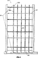
【図7】グラフ。
【図8】グラフ。
【図9】グラフ。BACKGROUND OF THE INVENTION
[0001]
The present invention relates generally to a method and apparatus for increasing power generation in a gas turbine, and more particularly to a method for increasing power generation in a land-based industrial gas turbine commonly used in power generation and chemical processing facilities. And device.
[Prior art]
[0002]
Gas turbines are used for a variety of useful applications. Aviation, voyage, power generation and chemical processing can benefit from various designs of gas turbines. Land-based gas turbine power plants also benefit from the combined cycle when a heat recovery unit is used to generate steam from waste gas generated by the gas turbine and the steam turbine is operated by steam. provide.
[0003]
With respect to common terminology, “gas turbine” as used herein refers to a turbine apparatus having a compression portion, a combustion portion, and a turbine portion. In recent years, the terminology “combustion turbine” is used to refer to the same machine. In this regard, this specification uses the term "gas turbine" to refer to both the term used so far, the term "combustion turbine" that refers to them at the present time.
[0004]
The gas turbine has a compression portion that compresses the input air, a combustion portion that combines the fuel and the compressed input air, and a turbine portion where energy from the hot compressed gas resulting from the oxidation of the fuel is converted to work. . Usually, natural gas (mostly methane), kerosene, and synthesis gas (such as carbon monoxide) are sent as fuel to the combustion section, but other fuels can be used. The rotor formed by the rotating shaft, the rotor blades of the attached turbine part and the rotor blades of the attached compressor part is mechanically in the compressor part and, in some cases, a compressor or generator used for chemical processing To provide power. Waste gas from the turbine section can be used to generate thrust forces and is a source of thermal energy or, in some cases, discarded. Some turbine parts use liquid cooled rotor blades where either compressed air, steam, etc. pass through the inner cooling cavities in the rotor blades used in the turbine part, which is hot Enable output.
[0005]
For several reasons, power generation from land-based industrial gas turbines grounded to power generation facilities, chemical processing facilities, and specific environments to allow for increased power capacity as required or required It is desirable to increase For example, in power generation embodiments, customer demand for equipment increases in summer in some locations to accommodate increased applications such as air conditioners, electric fans, and the like. Similarly, in chemical treatment equipment including electric intensive chemical treatment such as the conventional electrode chloralkali method, it may be based on the demand for products of electric intensive treatment capable of increasing the power generated from the gas turbine. desirable.
[0006]
One known method of increasing the power generated from a given gas turbine involves simply increasing the combustion temperature of the turbine, but this drawback of base load operation is that the elevated combustion temperature is at the hot end. There is a tendency to increase the thermal wear of parts and increase the frequency of power outages for maintenance. Evaporative cooling of the input air to the turbine is another known choice and offers significant advantages, especially in high temperature and dry environments, but the achievable increase from evaporative cooling is limited and prevails in the field. Depends on the atmospheric environment. Water injection into the turbine combustor and direct steam injection into the combustor shell or combustor are known, but there are disadvantages in terms of fuel economy losses, investment costs and costs associated with possible additional steam generation. Produce.
[0007]
Referring to the present invention, Applicants present a new practical means of achieving a significant level of power increase in industrial gas turbines. Here, water (or alcohol, or a mixture thereof) is preferably simple in terms of high latent heat of evaporation, readily available, and extremely low cost negligible for the user to obtain and use it. Water alone, which is essential, increases the power output performance of the gas turbine beyond the power that can be achieved with air. Water can be loaded into a gas turbine operating under load, and this process and effect is hereinafter referred to as “wet compression”.
[0008]
Without intending to limit the present invention, wet combustion allows for increased power, even in a fully (100 percent) effective evaporative input air cooled equipped gas turbine system. In part, the increase is achieved by reducing the work required to compress the input air. This thermodynamic advantage is realized in the compressor of the gas turbine via “latent heat mutual cooling”, where the water added to the air directed to the compressor is compressed with the air having the added water When it cools its air via evaporation. The added water can be considered as an “evaporating liquid sink” in this regard.
[0009]
The wet compression method reduces the amount of work (compresses air without added water), thereby driving a load attached to the gas turbine (in the case of a single shaft machine) or (single and two shafts). Either increase the compression speed to provide a large flow (which has value in both machines), or increase the effective work either.
[0010]
The increase in power possible by wet compression is slightly increased in the flow provided by the added and evaporated water. Also, increased power appears to contribute to increased air flow, which is known to occur initially at 10-20 gallons per minute (38 to 76 liters per minute). It should be noted that additional fuel is required to raise the temperature of the cooling air / steam that is exhausted from the compressor (in response to dry air compression), although the wet compression effect The value realized from is greater than the value of additional fuel required, resulting in a value that is added to the operation of the device as a whole.
[0011]
The possibility of adding compressor water in power build-up is understood by at least some of those skilled in the art at a theoretical level at some time, but other reference examples found and verified by the applicant are: Different conclusions have been reached regarding the overall benefits of adding water to gas turbine compressors and the effects on turbine or compressor efficiency and performance. An early example of the addition of water to a gas turbine compressor (1984, Massachusetts Technical Institute), entitled “High-efficiency Turbomachine and Gas Turbine Design” A six-stage centrifugal compressor, proposed by Wilson, used in a 1903 turbine built by Aegidius Elling between compressor stages, injected water between the compressor stages.
[0012]
In the 1940's, an overview of some of the principles behind wet compression is by ITWetzel and BH Jenninngs (published April 18-20, 1949 from the Midwest Power Conference, Illinois Institute of Technology). Pp. 376-380 of “Water Spray Injection of Axial Compressors”. This article shows that "water was sprayed into the upstream inlet duct from a 1/4 LNN6 nozzle of the four spray device types". The actual result does not use a gas turbine (as opposed to a small scale steam turbine).
[0013]
Similarly, the 1973 Soviet publication ("Water Spray Effect on Gas Turbine Engine Compressor Operation" 1973 LISlobodyanyuk, Enerqetika, No. 1, pp 92-95) describes "dry air" at the compressor air intake. Illustrates the effect of spraying 0.08 kg of distilled water and increases the power of the gas turbine engine by approximately 35 percent under these circumstances. However, for the Weztel and Jennings article, the equipment used in the Soviet example is not a gas turbine, but an idealized one that uses an interstage trap to discharge liquid water and is driven by a steam turbine. Compressor.
[0014]
In the development of jet aircraft as distinguished from land-based gas turbines, the injection of alcohol or water / alcohol mixtures is a machine titled “Interstage cooling of gas turbine compressors using methanol” by JACFortin and JFBardon Considered in the example provided in the American community of Engineer articles, which provided an increase in thrust for a very short period of time (eg at takeoff).
[0015]
In certain specific examples of land-based gas turbines, JPNolan and V. J. et al. Zumburi's 1990 ASME publication "Direct Mixing Evaporative Refrigerator for Gas Turbine Performance American Atlas Cogeneration Facility Rifle, Colorado" is a gas turbine with a baseline performance of 13.5 megawatts. As a replacement for conventional wet rigid media devices used to increase turbine power, "reports the structure and operation of a direct mixing evaporative cooling device. In this device, the “fogging device” of the spray device attached to the small diameter (0.5 inch to 1 inch) non-ferrous pipes operating at 600 psi or higher, which can be used in adjacent green house operation Designed to spray liquid water into the downward flowing air, it was constructed at the top of an extended (16 feet high) vertical air suction column. It has been shown that 7.5 gallons per minute must be output through the fogging device to provide the desired full humidity of the air introduced into the compressor (100 percent relative humidity). The flow performance of this design is “overspray” (ie, excess water is fed above full saturation entering the compressor) to be considered in terms of drift, pressure changes, leaks and other losses, and possible compressor failures. )), Compressor blade erosion, and compressor blade erosion as well as possible effective increase in mass flow associated with excess water.
[0016]
Several attempts were made to record the flow rate at atmospheric conditions over a range from July through September 1989. An average output gain of 9.6 percent is recorded over a 13.5 megawatt baseline output, with 7.4 percent input (from 87 ° F average atmospheric air temperature to 67 ° F wet valve temperature). Contributed to evaporative cooling of the air, 2.2 percent contributed a 1.3 percent increase in flow through the compressor (only accounting for the water input to the 1.3 percent air). At the same time, however, a decrease in gas turbine exhaust temperature of approximately 15 ° F. was observed and in response it was recorded that the ignition temperature increased to achieve an exhaust temperature limit of 1,000 ° F.
[0017]
The Nolan and Twombly articles have the ability to continuously input water into a relatively small gas turbine compressor that has a fully humidified input air system at its surface. Increased wet compression power is desirable for equipment such as that recorded by Nolan and Twombly, or for industrial gas turbines per Applicant's invention. In particular, it is possible to increase the net power of a large modern industrial gas turbine of the 35 megawatt class or higher and for a given gas turbine using humidified air.
[0018]
For example, Applicants are related to Nolan gas turbines with a 15 ° F upward shift in the control curve (as reported by Nolan and Twombly) and related to solid vane turbines from other manufacturers. According to Applicants' experience, this results in an overall “increase” of 2.2% or more of the power generation contributed by Nolan and Twombly to the increased flow through the turbine. As a result, even if Nolan and Twombly do not recognize this, those skilled in the operation and maintenance of these gas turbines are negative about the overall “overspray” effect on turbine output, and at best, little or no There was no positive effect, and a recorded added power level of 2.2 percent or less was recorded water treatment costs and possible negative long-term effects, liquids in addition to these turbine compressors The question arises whether to justify the increased maintenance costs seen from the extended period of water.
[0019]
Also, a similar “fogging device” embodiment of an industrial gas turbine, even if it is possible with the industrial gas turbine for Applicant's invention and where there are some forms of suggested wet compression. There is no recognition of the possible deformation of the turbine housing. Also, there is no content or suggestion to add water to achieve an increase level of more than 10 percent over the output achievable with fully hydrated air (ie, 10 percent or more via “overspray”) In the example of the cleaning process to solve the problem of failure found by the applicant, no teaching or suggestion is associated with a significant level of wet compression embodiment of an industrial gas turbine.
[0020]
Considering the intake of water into the compressor itself as another means of gaining power in an industrial gas turbine, especially the large of industrial gas turbines that can have a baseline performance of a hundred megawatts and above, Considering more recent models, despite some limited (almost twice) use of the increase in wet compression power reported in Nolan's article, due to some noteworthy comments recorded in the same article As reflected, there are a number of risks to some gas turbine systems that are readily known to those skilled in the art.
[0021]
One risk, as described above, is drawn from the corrosive action of the blades. Another difficulty (especially in large gas turbine systems) relates to the problem of localized non-uniform cooling (due to non-uniform distribution of added water) in the compressor, which is related to the housing and associated The physical components of the gas turbine apparatus are distorted in such a way as to cause damage caused by rubbing the rotor against the inner wall of the seal. If the gas turbine achieves complete thermodynamic equilibrium and the addition of liquid is nearly complete, another major factor in risk arises from the possibility of thermal shock. Another risk factor is due to the possibility of the liquid addition equipment parts being destroyed and colliding with relatively sophisticated moving parts of the gas turbine equipment. Another foreseeable risk factor is that when these impurities are deposited on the gas turbine component as a result of evaporation of the dissolved water, the impurities present in the water added to the compressed input air cause the gas turbine component to It is additionally related to failure and corrosion.
[0022]
Especially in connection with land-based gas turbine power generation facilities and chemical processing facilities, the risk factors described above are combined. Applicant provided and claimed here is a method and apparatus for practically implementing high levels of long-term wet compression in operation in industrial gas turbine power generation and chemical processing facilities. Such an apparatus makes it possible to directly benefit from the existing base of installed gas turbine power generation facilities and chemical processing facilities. Even more important in such an arrangement is to optimize the gas turbine engine in wet compression during the design phase, opening up new possibilities in power generation.
[0023]
Accordingly, it is an object of the present invention to deliver liquid water to allow growth in an industrial gas turbine through the addition of liquid water to the turbine compressor above a predetermined saturation or full humidity of the compressor input air. Thereby achieving an increase in the overall power output of the gas turbine. One already mentioned effect of the present invention is to reduce the temperature increase of the working fluid caused by compression, and in all other respects a generator installed above the entire power output that is available under comparable conditions or Increasing the power output available to continuously drive a chemical production compressor. In a preferred embodiment, an increase of at least 10 percent in the net power output of an industrial gas turbine is achieved beyond what can be achieved by fully effective evaporative cooling of the compressor input air.
[0024]
Another object of the present invention is to provide an apparatus and process in which the rate of addition (or removal) of liquid water is controlled to avoid the thermal shock described above and to attenuate the thermal shock. Another object of the present invention is to increase the power continuously for a period of time when the temperature of the working fluid is reduced to a level that allows the formation of harmful ice occurring at the inlet of the axial multiple stage compressor of the gas turbine. An apparatus and method for providing heat and humidity to a working fluid to enable
[0025]
Another object of the present invention is to provide a wet compressible power augmentation device and method for gas turbine compressor input temperature measurement, and (1) if ice breaks down, components downstream of the gas turbine Prevent the possibility of ice formation occurring at the entrance to the extent of damaging to (2) minimize the use of freezing control materials such as steam or the use of freezing point suppression (3) To provide input to a controller used to regulate, monitor and / or control the overall water addition apparatus and method. In another preferred embodiment, a window is provided near the compressor inlet so that icing is visible.
[0026]
Another object of the present invention is to provide housings up to approximately predetermined acceptable limits determined when retrofitting with tolerances applicable in conventional operating modes to prevent damage to the multi-stage compressor of the gas turbine. It is an object of the present invention to provide an apparatus and method for ensuring a sufficiently uniform distribution of liquid water in the working fluid to limit the deformation of the (casing). Another objective is to add about enough water to achieve about 10 percent increase in turbine power, and more than can be achieved with fully moist air to prevent this damage Measuring and controlling the angular distortion and deformation observed in industrial gas turbines to prevent.
[0027]
Another object of the present invention is to effectively add water to the compressor portion of the gas turbine toward the inlet air with minimal additional danger to the turbine from the elements carried by the input air toward the turbine compressor inlet. It is an object of the present invention to provide a wet compressible power augmentation apparatus and method. In the case where a device is added that adds such water at a distance sufficiently away from the inlet of the compressor part, so that the element of this device is destroyed and conveyed with input air towards the compressor inlet, this element is Progressively drawn to the underside of the inlet duct used to convey air to the gas turbine before entering the compressor inlet, and (b) fog through a device (controllably increasing the flow of water to the compressor) Provides sufficient water to the input air and provides sufficient transport to the compressor portion of the turbine to achieve a predetermined increase in turbine power when at a predetermined distance from the compressor inlet. Is done.
[0028]
Another object of the present invention is to provide liquid cooling rotation of the turbine section so that the cooling passages of these rotor blades can be detected in the earliest time due to the effects of water impurities added via the apparatus and method. It is an object to provide a power augmentation apparatus and method that is wet compressible to monitor the temperature profile of the blades. Further, an object related to the present invention is to provide a power source of the type described herein that adequately resolves the attraction and deposition of impurities from water added through the apparatus and method beyond the first few rows of compressor blades. To provide an effective on-line cleaning method for industrial gas turbines using augmentation methods.
[0029]
In this regard, gas turbine compressors are periodically cleaned to accumulate particulate deposits of inner parts. In some of this cleaning, after the gas turbine is enabled for cleaning operation, the rice, chemical cleaning mixture is sprayed or input to the inlet of the gas turbine. At least one such chemical mixture is shown in US Pat. No. 4,808,235 entitled “Cleaning Gas Turbine Compressor” granted February 28, 1989.
[0030]
Another device for minimizing particles trapped in the inner parts of a gas turbine is, for example, U.S. Pat. No. 4,926, granted to Donle on May 22, 1990 and entitled “Cleaning Gas Turbine Input Air”. , 620, and the gas turbine input air cleaning. It is another object of the present invention to provide an off-line turbine cleaning method adapted for use with turbines using the power augmentation apparatus and method of the present invention.
[0031]
Another object of the present invention is to provide a wet-compressible power increasing device that can be widely used with an axial compressor and a rotary displacement compressor or a centrifugal compressor. Another object of the present invention is a wet compressible power augmenter for use with a gas turbine having an axial compressor and an input air duct whose flow axis is aligned with the rotational axis of the gas turbine rotor. Is to provide.
[0032]
Another object of the present invention is a wet compressible power augmenter for use with a gas turbine having an axial compressor and an inlet air duct whose flow axis is perpendicular to the rotational axis of the gas turbine rotor. Is to provide. In addition, it is another object of the present invention to provide a rotor blade for the turbine portion so that the clogging associated with impurities in the water in the cooling passages of the rotor blades of the turbine portion is minimized or substantially does not occur. It is an object of the present invention to provide a wet compressible power augmentation apparatus and method for pre-filtering compressed air in an axial compressor section prior to cooling. It is another object of the present invention to provide an apparatus and method that can be easily set to a currently operating gas turbine apparatus without the need for substantial maintenance, modification or “disassembly” of the gas turbine engine. It is. Another object of the present invention is to provide a retrofit to economically achieve evaporative cooling of the compressor input air as well as increased power by adding more water to a gas turbine without evaporative input air cooling means. It is to provide a device that is applied as a basis.
[0033]
The present invention, in one aspect, relates to a method used for 6 hours or more within 24 hours to increase the overall output of an industrial gas turbine to drive a generator or compressor, An axial flow multi-stage compressor having an inlet for obtaining a working fluid having a flow rate, the method comprising providing a sufficient amount of liquid water with liquid droplets to the working fluid obtained by the axial flow compressor. And used to drive the generator or compressor, reducing the temperature increase of the working fluid caused by compression (when measured without providing the droplets to the total output of the gas turbine at comparable conditions) It has a way in which an increase in the overall power output of a possible gas turbine is realized.
[0034]
In a first aspect of the invention, this increase is at least conventional at the inlet of a compressor of an industrial gas turbine that includes a separate conventional evaporative input air cooler, for example, a cooler or a media type evaporative cooler. This is achieved by providing a water wash amount of compressor water for an extended period. Compressor cleaning is currently performed to recover turbine performance (power output) lossy parts related to dirt from compression of air with normal moisture.
[0035]
In accordance with this particular aspect of the present invention, to increase power generation in an industrial gas turbine with an on-line compressor cleaning device in response to an anticipated or actual increase in power demand from the turbine. Also, in order to maintain the desired level of power generation due to changes in atmospheric air conditions, for example, an existing on-line compressor cleaning device continuously adds a wash amount of compressor water. However, in contrast to the primarily used on-line compressor cleaning devices that generate a coarse cleaning spray to remove faulty compressor deposits, preferably in power-enhanced embodiments, preferably 200 microns or less. An average droplet diameter of water is advantageously fed as a fine mist or throughout. In the method embodiment described above, a second aspect of the present invention relates to controlling and increasing the amount of fluid water provided at the inlet of an axial multi-stage compressor.
[0036]
In a related embodiment, the present invention has an axial flow multi-stage compressor that acquires and includes a working fluid that includes air, including adding droplets of liquid water to the working fluid obtained by the compressor. A method of increasing the overall power output of a gas turbine, wherein the flow rate of the liquid droplets is varied with time to adjust the thermal stress in the gas turbine, and this thermal stress causes the liquid of water to flow into the working fluid. Providing and providing droplets of liquid water to the working fluid obtained by the compressor at a substantially constant flow rate to increase the overall power output of the gas turbine by wet compression.
[0037]
Another aspect of the invention provides heat and moisture to allow continuous power increase during periods when the temperature of the working fluid drops to a level that allows the working fluid to form harmful ice at the inlet. About doing. Yet another aspect of the present invention provides a sufficiently uniform distribution of liquid water in the working fluid to limit angular deformation of the housing to a predetermined acceptable limit that prevents damage to the axial flow multi-stage compressor. Including the stage of guaranteeing. Thus, it provides a way to monitor the temperature profile of the liquid cooled rotor blades in the turbine section when the combustion gas exchanges its kinetic energy with the rotor blades. The temperature profile of the fluid-cooled rotor blades is a measure that helps to identify the clogging from minerals or other condensed solids from the water atomized by the compressor airflow used to cool the turbine blade rotor blades It is. The temperature profile is also useful in discriminating from the corrosive effects of water that is conveyed through the compressor to the turbine section and from the solids of the compressor air flow that cause damage on the surface of the multi-layer turbine section.
[0038]
The present invention thus provides a method for temperature measurement at the compressor inlet, where (1) ice can be formed at the inlet to the extent that the ice breaks and damages downstream components of the gas turbine. (2) freezing control materials such as steam or minimizing the use of freezing point suppression and / or (3) coordinating, monitoring and monitoring total water addition equipment and methods Provide input to a controller used to control.
[0039]
Aspects related to the additional method of the present invention are the book of compressor failure materials resulting from soluble deposits left behind by evaporation of the added water and other air acquired by the compressor through the air input section. The present invention relates to an on-line cleaning method for an industrial gas turbine compressor that uses the power augmentation method of the invention, and this method includes: periodic or intermittent periods when cleaning is instructed or desired. (A) Increasing the mist of liquid fine water added for the purpose of increasing power with increased conventional washing or increasing the corresponding water flow in one or more conventional coarse washings to one or more fine Provided on a substantially continuous basis for the purpose of replacing the increase in fog and (b) increasing power. Intermittently or periodically supplying one or more additional fine mist increments to the reservoir, and (c) periodically or intermittently controlling all additional water to the compressor And a method comprising at least one of the steps of operating for a sufficient time without adding such water to evaporate or break up the dirt deposits.
[0040]
In another preferred on-line cleaning method that is preferred for the use of a turbine with slot-actuated inlet guide vanes, the large penetration of liquid water into the compressor section is one of the water addition capacities described above during on-line or It is similarly achieved without supplying a plurality of stored increments, correspondingly reducing the air input to the compressor. Other means of online cleaning store one or more additional cleaning increments of liquid water when the other means of online cleaning allow the desired flow rate to the compressor to continue. In particular, it is advantageous not to invest additional funds, in which case, for various reasons, it is impossible or advantageous to exceed the desired flow rate to be used for augmentation purposes. It is.
[0041]
In another process aspect of the present invention, there is provided an off-line compressor cleaning method for use in an industrial gas turbine using a wet compression power increase according to the present invention, which method drives the turbine at an initially reduced rotor speed. And a step of cooling the compressor at a second rotational speed when continuously preparing and preparing foamable cleaning components. Thereafter, a first reduced suitable for dispensing foamed cleaning components over the length of the turbine compressor in the suction and wash steps and one or more iterative steps described in two consecutive sequences A rotational speed between the rotation and the second rotational speed is established. A reduced suction rotational speed is established at about 0 revolutions per minute or more (but less than the second rotational speed) and the cleaning component is left in place for a predetermined time. The rotational speed is increased sufficiently to remove foam from the compressor and is completed (by the water addition equipment used in performing the wet power increase of the subject turbine) before restarting the turbine.
[0042]
The present invention, in various embodiments, is a conventional water scrubber (preferably, when used alone, the compressor scrubber is preferably a fine feature characterized by droplets with an average diameter of 200 microns or less. A type suitable for supplying mist spray), at least one spray rack water pipe, at least one spray rack water nozzle, or conventional compressor water cleaning equipment (fine mist or coarse spray) and spray A combination of rack group assemblies. In addition, the present invention provides a power augmentation device that uses a laser emitter and a laser target measurement device mounted on the outside of the housing to detect deformation of the housing.
[0043]
In addition, the present invention provides a power augmentation device that uses an optical pyrometer that monitors the radiant energy of each of the cooling rotor blades through the viewing tube and is characterized by the temperature profile of each of the fluid cooled rotor blades. In addition, the present invention uses a temperature sensor for monitoring the temperature in the compressor inlet area to (1) prevent icing from occurring at the inlet to the extent that damage is induced downstream by damaging the gas turbine or depleting the compressor. Preventing, (2) freezing control materials such as steam, or minimizing the use of freezing point suppression, and / or (3) coordinating, monitoring and / or controlling the entire wet compression apparatus and method Provide input to the controller used to do this.
[0044]
Furthermore, the present invention provides a wet compression power augmenter that provides a process control computer that executes process control logic to control the flow atomized to the compressor inlet so that deformation of the gas turbine housing is minimized. I will provide a. Other features and advantages of the present invention will become fully apparent upon reading the detailed description of the preferred embodiments of the invention in these various aspects and upon viewing the accompanying drawings.
[0045]
Definition of terms
“Industrial gas turbine” means a megawatt turbine of at least 20 megawatts or more used for land-based power generation of industrial and power generation facilities. “Powerful gas turbines” are not designed to undergo very large abrupt changes in power output from a design perspective. Powerful gas turbines are specifically intended to distinguish them from aircraft turbines. Aircraft turbines are configured to use a particularly large amount of liquid water in normal operating environments and operations as opposed to powerful gas turbines.
[0046]
“Working fluid”, usually the working fluid of a gas turbine is a gas. The normal working fluid of a gas turbine compressor is moisture-containing air. In the present invention, the working fluid is expanded including liquid water. The working fluid changes its composition as it travels through the industrial gas turbine (ie, through material injection and combustion processes). In this regard, as the working fluid travels through the gas turbine's work cycle, the gas mixture, the gas mixture's bilayer liquid, the gas mixture's bilayer mixture, or at various locations along the axis of the gas turbine, Either a gas fluid and a three-layer mixture of solid particles.
[0047]
“Overall output” refers to the net output of the gas turbine and refers to the effective shaft power that drives the generator or processing compressor (outside of the gas turbine). The overall power output of the gas turbine is measured by the torque and speed of the rotor shaft and can be expressed in either horsepower or megawatts. When expressed in megawatt terms, the terminology net output includes power generation losses. When comparing the overall output at comparable conditions, when providing liquid water, and when there is no liquid, the comparable condition includes a comparable method of measuring the overall output.
[0048]
“Addition of heat and moisture” refers to simultaneously adding heat and humidity to the working fluid up to the saturation point of the working fluid. “Angle change” refers to housing bends or distortions that cause mutual interference between the turbine rotor and the housing. “Damage” means a detrimental change in gas turbine components beyond what is expected during reasonable use and operation. With respect to wet compression, some acceptable degree of corrosion of the blade coating or blade material is expected.
[0049]
“Water” is effective in compositional properties for use in gas turbines for the purpose of increasing power by wet compression. It leaches out the components of alloys used, for example, to reduce the nature of water added to corroded turbine parts and to treat or manufacture various structural parts of gas turbines in contact with water To contain impurities such as freezing point suppression or materials and conventional or effective additives. “Varying multiple flow increases in a balanced manner” refers to the increase in water added to the working fluid.
[0050]
As used herein, a “balanced method” refers to a gas turbine with an acceptable angle after either an increment is drawn from or added to the aforementioned set. An increase that does not cause distortion of the housing.
[0051]
“Sufficiently uniform distribution” refers to the distribution of liquid water of the working fluid obtained by the compressor, which is beyond the acceptable angular distortion limit and does not result in distribution of the gas turbine housing. Causes distortion of liquid water. “Improved fuel efficiency” refers to the generation of power output per unit of fuel when liquid water is added to the working fluid that is greater than the output when the water is not added to the working fluid.
[0052]
Referring to FIG. 1, an overview of a gas turbine generator used to generate power from the combustion of air and fuel is provided, which is an example of a facility that uses the apparatus and method of the present invention (merger The generated generator is shown in FIG. 1 but is assumed to be obvious). The gas turbine
[0053]
The
[0054]
In some cases, the
[0055]
2A and 2B show the
[0056]
The
[0057]
Various gases and fluids within the
[0058]
In the
[0059]
After adding fuel to the
[0060]
Each
[0061]
In some cases, the
[0062]
As described elsewhere in this specification, the use of such a cooling device for the
[0063]
A preferred method of preventing such material from entering the cooling system of the
[0064]
Extensive pre-filtration of the compressed air sent from the axial compressor before being used to cool the turbine
[0065]
FIG. 3 provides water particles to the working fluid acquired by the
[0066]
In this aspect, the present invention includes providing a working fluid to the compressor comprising 1% by weight of at least about 3/4, preferably 2% to about 8% by weight of liquid water. .
[0067]
Preferably, an increase of at least 10% and most preferably an increase of about 20% to 40% of the overall output of a gas turbine such as
[0068]
With particular reference to FIG. 3, a preferred apparatus for adding liquid water to the working fluid acquired by the
[0069]
Remote positioning, which provides the advantage of preventing parts of the spray
[0070]
The use of a coarse spray reduces the amount of liquid water added to the working fluid to ensure sufficient uniformity of liquid water distribution in the
[0071]
Further, those skilled in the art will recognize that if the nozzle, for example, some other structural element of the particular water addition means breaks apart, it distributes the uniform distribution of working fluid water towards the compressor inlet. Obtaining a sufficiently fine mist to guarantee and safely saturate the first compressor stage to obtain a full flow fluid with wet compression is desired (in the embodiment of the spray rack assembly 201). In order to distribute the amount of water considered for increasing the amount of water, a large number of
[0072]
The optimal apparatus and configuration for distributing liquid water to the working fluid obtained by the compressor is usually at the lowest overall cost and the overall level of a given power increase to achieve full saturation of the first compressor stage. Compatible with devices and configurations that derive maximum flow benefit from the addition of water. This is considered to occur without causing excessive distortion of the
[0073]
Thus, at a level below the increase (up to about a 10 percent increase), as previously mentioned, it is sufficient to use the compressor water wash configuration, thereby providing a conventional liquid water compressor. The amount of water washed (which varies with turbine type and size, but is 0.1 to 0.5% depending on the weight of the working fluid) is the time extended to the working fluid acquired by the compressor Preferably, the nozzle of this example is of the type that supplies water so that the fine mist has an average droplet size of mainly 200 microns or less, but it is very fine When using the mist nozzle, the liquid water of the working fluid generated by the clogging of the fine mist nozzle near the inlet of the compressor When necessary to cover "gaps" in the distribution, the adding device auxiliary water placed upstream, the use (i.e., to be removed from the
[0074]
In certain embodiments, particularly preferred nozzles are manufactured by Rochem Technical Service under the name FYREWASH and are 100 and 200 at a pressure drop of approximately 80 pound gauge (psig, or 550 kPa gauge) per inch. Characterized by being input to an input air vapor that provides a fine mist spray with an intermediate mean droplet diameter that is rated by the applicant (but greater than about 70 microns). .
[0075]
Typically, as described in the previous paragraph, in some circumstances, with regard to providing supplemental water addition means, a conventional compressor water supply device for liquid water to the working fluid is used to clean the compressor water. For the purpose (for example, annular spray pipes with spray nozzles equally spaced around the annular spray pipe), the same one used for a given turbine in compressor water washing, the person skilled in the art A detailed description of the same content is not made so that it is often acquired.
[0076]
If a large level of increase is desired, i.e. an increase of more than 10%, in particular an increase of more than 20% of the total output of the gas turbine, preferably one or more spray
[0077]
With respect to the spray
[0078]
Preferably, very clean water, for example, water having a conductance of 0.4 microns or less without particles, concentrated water, diluted water, ionized water is preferably very fine water Atomized (ie, sprayed) to form a spray or mist. A number of known commercially available nozzle configurations have been used to provide very fine water sprays, such as very fine water sprays such as (77003 Houseton, Texas 610N
[0079]
Pure water impacts the components of the gas turbine engine. In this respect, the technically ideal water is obtained, for example, from a method that passes through a promoter. According to such a promoter, the water flow is compositionally balanced so that it contains a sufficient amount of each important alloy element corresponding to the manufacturing material of the components of the
[0080]
As suggested by the spray
[0081]
However, water is most preferably added or reduced in a step-wise manner using multiple increments of water when increasing or decreasing its flow. With regard to using multiple water flow increments, a preferred apparatus for practicing the present invention has a
[0082]
As another example, those skilled in the art will recognize that each
[0083]
Furthermore, as will become apparent, if the water is operated at a continuous flow rate or a flow rate that increases, the water flow rate achieves an unacceptable spray for inclusion and mixing in the input air. It is deformed to a slope that is below the minimum required amount of water, and by adding this water, it is basically added, but is not atomized at the
[0084]
When this pressure is controlled by the spray
[0085]
In other embodiments, each individual spray
[0086]
A number of differently configured nozzles and pipes provide liquid water to the working fluid acquired by the high-level wet compression power increased
[0087]
Basically, however, what is needed is that the liquid water flow provided to (or removed from) the working fluid is (a) thermal stress applied to the
[0088]
Another desirable configuration and method of adding liquid dripping to the working fluid obtained by the
[0089]
According to Applicant's experiments, for example, the droplets sent to the working fluid by the
[0090]
The angular deformation of the
[0091]
When this device is added to the turbine for a particular inlet configuration in the addition of a flow rate of liquid water, the water addition device so configured may be used when no measurements are being made (eg, the measurement device Is expected to be able to operate reliably to control deformation within substantially predetermined acceptable limits. In this regard, the measuring device is most advantageously used for design purposes, and after the angular deformation of the
[0092]
Most desirably, a sufficiently uniform distribution of the working fluid liquid water provides liquid water to the
[0093]
However, depending on the positioning of the spray
[0094]
In the aforementioned features or aspects, if this mode of operation is feasible, the spray
[0095]
FIG. 4 shows details of the outline of the spray
[0096]
FIG. 5 shows a top view assembly of the spray rack assembly of FIGS. 3 and 4 and continues for a predetermined period when the temperature of the working fluid drops to a level that allows the formation of harmful ice at the inlet. A preferred method of applying heat and humidity to the working fluid to allow for increased power is shown. A preferred method includes providing steam to the
[0097]
If the spray
[0098]
It is important to manage the input air temperature at the
[0099]
If no heat is provided, this temperature limitation, for example, via steam holes 315 or other means, effectively places the ambient temperature in the gas turbine using the compression technique of the present invention with pure water. I understand that. However, it is provided through the addition of steam (generated from low pressure steam that is effective in a facility operating in a cycle combined with a
[0100]
With respect to combined cycle operation and evaporative input air cooling, additional current unusable heat is the heating of the input air (effectively adjusting the evaporative input air cooler to the evaporative input air heater / humidifier) and Injection of added steam that is further recovered and effectively applied for the purpose of heating the input air by alternately exchanging the heat of the concentrator from the steam turbine to an evaporative input air cooler (not shown) for humidification purposes (Or without steam injection), the operation of the wet compression technique of the present invention will be possible at atmospheric temperatures below 45 ° F. (7.2 ° C.) and 15 ° F. (−9.4 ° C.), Actually, the lower temperature operation is more appropriately determined on a case-by-case basis.
[0101]
An additional safety measure against potentially broken ice that occurs at the
[0102]
FIG. 6 represents details of one possible means of monitoring the additional associated liquid water deformation of the
[0103]
FIG. 6 shows a
[0104]
The asymmetric cooling effect of the
[0105]
As described above, positioning, definition of water increments, and individual
[0106]
The improvement of the wet compression-related instrument of the present invention relates to the use of a liquid presence sensor in the combustion portion that confirms the presence of inlet liquid to the combustion portion at the compression outlet. In this respect, liquid is not detected at the outlet of the compressor (inlet to the combustion section) or (if the
[0107]
In order to assist in the operation of the
[0108]
In addition, the control computer measures the temperature of each temperature sensor, measures the input from the spray
[0109]
The process control computer takes into account the power requirements from the associated gas turbine or
[0110]
In operation, in an apparatus having the ability to provide a high level increase in the overall output of an industrial gas turbine as desired in chemical processing and industrial power generation operating environments, the atomized water stream is a water addition device. During startup and shutdown of the engine, the thermally induced thermal stresses in the
[0111]
Thus, for example, the increased dimensions and air gaps prevent the
[0112]
Further, the adjustment of the increase in the amount of atomized water is performed based on the position as described above. In this aspect, for example, the measured distortion of the
[0113]
Positionally and with respect to time, positive and negative increases in water must be added or subtracted in such a way as to adequately minimize destructive heat and mechanical stress on the
[0114]
In this aspect, the discussion of wet compression seen by those skilled in the art described above, including the implementation of short-term wet compression of aircraft and several examples of land-based turbine wet compression increases reported by Nolan and Twombly, Necessary for facilitating wet compression in a large machine that is overloaded. In early implementations where there is a discussion of wet compression known to the applicant, the liquid added to the wet compression of these small gas turbines is essentially turned on (or alternately turned on) in one increment. Down or turned off).
[0115]
This is because (1) small gas turbines (especially those used in aircraft) are not dimensionally sensitive to cooling effects. (2) The use of wet compression is at least a relatively short time in the case of an aircraft. (3) The level of increase in the extended time is relatively small. In large land-based industrial gas turbines, the liquid added to wet compression should basically be “turned on” in multiple incremental increments in position and time. (1) Because large gas turbines are dimensionally sensitive to the associated cooling effects from the added liquid, (2) the use of wet compression is maintained over time, and (3) the level of increase Is very important and means a large amount of addition. Nevertheless, it will be apparent to those skilled in the art to introduce large amounts of water into any type of gas turbine so that thermal expansion and contraction in the gas turbine is advantageously neutralized.
[0116]
As a result of the level of water addition considered by the present invention, when deposits are deposited on the compressor by evaporation of the added liquid water, these deposits are now cleaned by conventional coarse spray compressor cleaning equipment. It has been found to occur beyond the first few rows of compressor blades. When these droplets accumulate in the compressor, some performance loss is expected to be solved, depending on the on-line cleaning equipment and processing method, but clean the compressor by offline cleaning or by opening the compressor and manual equipment. Is only solved through an unfavorable choice.
[0117]
Applicants have developed a new on-line compressor cleaning method for cleaning the compressor portion of an industrial gas turbine that uses increased wet compression power over time. In one embodiment, if the cleaning exhibits a loss in turbine performance, for example, the atomized streams provided by the spray
[0118]
As another example, the coarse spray increment (effective for cleaning the first few rows of compressor blades) can be omitted or easily implemented in the form of existing conventional coarse spray compressor cleaning devices. Not available. The fine cleaning increment is used to clean the first few blade rows. After that, a large row of finer compressor blades that are sufficiently inverted, for example, a larger row of compressor blades is not available, and 7, 8 and higher rows of axial flow multistage compressors are not available, Each of the spray rack increments is preferably controllably removable, and the turbine is periodically cycled without adding water to cause droplet evaporation and / or cracking in these areas of the compressor. Or it is operated intermittently.
[0119]
Where off-line cleaning is warranted, the present invention is adapted for use in industrial gas turbines that create industrial applications with large and sufficient use of increased wet compression power. According to an aspect of the features according to the invention, the turbine is taken offline at a reduced rotational speed as in the prior art (usually in the range of 1000 revolutions per minute without 900) and for a predetermined time. By cooling (by turbine use and procedure) and configured in off-line compressor cleaning. A rotational speed that is intermediate between the initial gear speed and the second cooling or rotating gear speed is established, which is suitable for distributing the speed formed through the length of the compressor. The predetermined value of the formed cleaning component is input to the compressor via conventional means such as an air ejector.
[0120]
Various compressor cleaning soaps and ingredients are known for this purpose, which is easily made to form a suitable foam and form a foam by the use of certain molding agents. Following the introduction of the cleaning component, a reduced soaking rotational speed is established. Soaking is continuous as long as it is practical with respect to the scheduled restart of the turbine. The rotor speed then drains the molded cleaning components from the compressor and transmits the liquid groove cleaning agent through the length of the compressor, and the liquid water is fed through the wet compression water addition device. It is preferable. Preferably, the turbine is filled with a cleaning component at a second time, dipped and cleaned again. The liquid wash water is preferably supplied through an apparatus for adding wet compressed water. Preferably, the turbine is filled with a cleaning component in which bubbles have been generated, dipped and washed again at a second time. Wash water is suitably discharged from the turbine, which is reconfigured for operation and started again.
[0121]
Summarizing the foregoing, while numerous embodiments have been described in the method and apparatus of the present invention, those skilled in the art of gas turbines will at the same time consider that the described embodiments are possible and effective embodiments of the present invention. It will be understood that this is defined by the following claims in the absence of means. Thus, the most preferred form of liquid water droplets on the working fluid is to use the
[0122]
Further, the laser emitter and laser target technology provides an excellent and inexpensive method and apparatus for use in controlling the angular deformation of the
[0123]
Furthermore, the power plant, system and method of the present invention have been specifically described in a gas turbine including an axial compressor. However, it will be readily apparent to those skilled in the art that the apparatus, systems and methods described herein may be used with other types of compressors known or used in gas turbine systems. These other types of compressors are rotary positive displacement compressors and centrifugal compressors.
[0124]
Example 1
An example of wet compression is an estimated power increase of 26% over the base load capability of a Westinghouse W-501A turbine with an existing evaporative inlet air cooling system, 130 ° F (54.4 ° C). Atomized hot 89 gallons per minute (337 liters per minute) of water (which is between 165 ° F and 73.9 ° C) is introduced into the turbine compressor. Five increments are used through the spray
[0125]
The spray mist device is set in the input air ducts of the two westing houses W-501A according to FIGS. 1 to 6 of the present application. Each of the five spray nozzle headers of such a device is capable of providing a common water that can provide approximately 80 psi (550 kPa) to the nozzle after calculating the pressure drop associated with the limiting orifice of each of the five header supply lines. The supply can be communicated individually via valves. The mist is fine enough (150 to 200 microns) to contain small drops of air water flowing by the axial compressor.
[0126]
Based on calculations incorporating air velocity, drag coefficient, and nozzle weight, this distance provides a drop time to prevent damage to the compressor if the spray nozzle breaks and loosens. Limiting the orifices of the individual nozzle rack supply lines limits the flow to approximately 35 gpm (gallons per minute, 132 liters per minute) if the line breaks or the nozzles are lost, and the compressor stops And be controlled not to induce surges. The computer also monitors for excessive flow beyond the expected speed. This delivery system was used in conjunction with a coarse spray compressor wash system (annular nozzle) to deliver a total of 89 gpm (337 liters per minute) by wet compression.
[0127]
A self-contained diode (firearm target) laser with a limited spot size is mounted between the front support legs in close proximity to the compressor at an advantageous location. A reflective mirror is mounted at a conventional location in the compressor shell that moves axially at a distance measured approximately 102 inches (2.6 meters) from the emitter. The change in position of the target (delta) point defines the change in angle between the two mounting positions (alpha) by the following relationship: alpha = arc tangent [delta / (2 × 10²)]. An angle change of 0 °, 5 minutes, 6 seconds is dictated by the angle of distortion between operation with the existing compressor washer plus (with partially clogged nozzle) center spray rack and drying operation. The This is defined by the change in target position of the 0.303 inch (7.7 millimeter) laser. This represents the maximum distortion observed between the dry compression and the maximum water used in this wet compression experiment (89 gallons per minute or 337 liters). The observed angle of this distortion is the maximum allowable set in the test, and the rubbing of the rotor based on the tip of the 0.090 blade at the laser and mirror attachment point (102 inches or 2.6 meters), It represents approximately 80% of the allowable angle of distortion required to create the seal gap, machine geometry, or laser attachment point.
[0128]
A 12 ° F (6.7 ° C) downshift in the control curve and a "net" power increase of 8.2 megawatts tuned for an intentional decrease in ignition temperature by a 3 ° F compressor inlet temperature change Without being shown at approximately 80 ° F. (26.7 ° C.) compressor inlet / evaporative cooling and
[0129]
Example 2
The Westinghouse W-501A gas turbine (providing greater than 80 percent relative humidity input air) is equipped with the spray atomizer described and shown herein (Illinois 60189). It consists of 5 spray headers (including from Wheaton PO Box 7900 spray equipment) that contain the whole of type 1-7N-316SS16 noise. As a result, it has the ability to provide atomized liquid water in excess of 90 gallons per minute of the turbine compressor.
[0130]
As shown in FIGS. 7-9, a first header is activated that provides an initial power generation level of about 33.6 megawatts and about 15.2 gallons of water per minute of atomized hot concentrated water. An increase in power generation to about 37.3 megawatts is achieved, and an increase of 3.7 megawatts or about 11 percent is achieved based on the starting power generation level. A second header or spray rack is added so that there is no additional decrease in measured input air temperature, increasing the level of atomized water to about 30.4 gallons per minute (115 liters per minute) An increase from about 1.3 megawatts to about 38.6 megawatts was realized. The addition of a third spray rack carrying a stream of water up to about 48 gallons per minute results in about 40.0 megawatts (about 1.3 to 1.4 megawatt increase) of power generation from the gas turbine. A total atomized water volume of approximately 67 gallons per minute (254 liters per minute) results.
[0131]
An increase of 67 gallons per minute of atomized liquid water added to increase is about 7.5 megawatts, or First Power generation Against About 22.3 percent The Increased, about half of which was achieved by increasing the amount of first atomized water. A significant increase in actual input air flow was observed simultaneously with the start-up of the first spray rack.
[Brief description of the drawings]
[0132]
FIG. 1 shows a schematic diagram of a typical gas turbine power generation facility.
FIG. 2A shows details of a gas turbine engine having an axial compressor.
FIG. 2B shows details of a gas turbine engine having an axial compressor.
3 shows a combined evaporation pipe showing the positioning of the spray rack group assembly used in the gas turbine power generation facility of FIG. 1, and FIG. 3A shows the spray rack group assembly and steam pipe. FIG.
FIG. 4 is a detailed view of the spray rack layout showing the relative location of individual spray rack water pipes, the location of each spray rack water nozzle and the use of the spray rack stiffener.
FIG. 5 is a detailed view of the spray rack assembly of FIGS. 3 and 4 with a steam manifold that directs flow to the steam pipe.
FIG. 6 shows a detailed view of monitoring the deformation of the housing of the gas turbine engine apparatus shown in FIGS. 1 and 2, for example.
FIG. 7 is a graph.
FIG. 8 is a graph.
FIG. 9 is a graph.
Claims (3)
軸流多段コンプレッサによって獲得された作業流体に大きな潜熱を有する水の小滴を次第に増大する方法若しくは段階的に増大する方法で添加し、前記水の小滴の量は、前記コンプレッサの入口の湿度が飽和された空気にその1重量%の少なくとも3/4の液体の水を加えた作業流体を提供するものとされ、圧縮によって生じる作業流体の温度増大を低減し、それによってガスタービンの正味出力の増大を達成する工程、
前記コンプレッサのハウジングの変形を監視する工程、並びに
所定の公差に前記変形を制限するために前記水の小滴の添加を制御する工程を含む方法。A method of increasing the net output of an industrial gas turbine including an axial multistage compressor having an inlet that captures a working fluid containing air, comprising:
Water droplets having a large latent heat are added to the working fluid obtained by the axial multistage compressor in a gradually increasing manner or in a stepwise increasing manner, the amount of the water droplets being the humidity at the inlet of the compressor Provides a working fluid with 1% by weight of its saturated water added to at least 3/4 liquid water to reduce the temperature increase of the working fluid caused by compression, and thereby the net output of the gas turbine Achieving an increase in
Monitoring the deformation of the housing of the compressor and controlling the addition of the water droplets to limit the deformation to a predetermined tolerance.
Applications Claiming Priority (5)
| Application Number | Priority Date | Filing Date | Title |
|---|---|---|---|
| US08/645,781 | 1996-05-14 | ||
| US08/645,781 US5930990A (en) | 1996-05-14 | 1996-05-14 | Method and apparatus for achieving power augmentation in gas turbines via wet compression |
| US08/715,675 US5867977A (en) | 1996-05-14 | 1996-09-18 | Method and apparatus for achieving power augmentation in gas turbines via wet compression |
| US08/715,675 | 1996-09-18 | ||
| PCT/US1997/008757 WO1997043530A1 (en) | 1996-05-14 | 1997-05-02 | Process and apparatus for achieving power augmentation in gas turbines via wet compression |
Publications (2)
| Publication Number | Publication Date |
|---|---|
| JP2000510544A JP2000510544A (en) | 2000-08-15 |
| JP3749546B2 true JP3749546B2 (en) | 2006-03-01 |
Family
ID=27094777
Family Applications (1)
| Application Number | Title | Priority Date | Filing Date |
|---|---|---|---|
| JP54121397A Expired - Lifetime JP3749546B2 (en) | 1996-05-14 | 1997-05-02 | Method and apparatus for achieving increased power in a gas turbine via wet compression |
Country Status (15)
| Country | Link |
|---|---|
| US (1) | US5867977A (en) |
| EP (2) | EP1108870A3 (en) |
| JP (1) | JP3749546B2 (en) |
| KR (1) | KR100375648B1 (en) |
| CN (1) | CN1123680C (en) |
| AT (1) | ATE225906T1 (en) |
| AU (1) | AU725901B2 (en) |
| BR (1) | BR9709317A (en) |
| CA (1) | CA2254922C (en) |
| DE (1) | DE69716259T2 (en) |
| DK (1) | DK0898645T3 (en) |
| ES (1) | ES2181003T3 (en) |
| PT (1) | PT898645E (en) |
| RU (1) | RU2178532C2 (en) |
| WO (1) | WO1997043530A1 (en) |
Families Citing this family (100)
| Publication number | Priority date | Publication date | Assignee | Title |
|---|---|---|---|---|
| JP2877098B2 (en) | 1995-12-28 | 1999-03-31 | 株式会社日立製作所 | Gas turbines, combined cycle plants and compressors |
| US6256976B1 (en) | 1997-06-27 | 2001-07-10 | Hitachi, Ltd. | Exhaust gas recirculation type combined plant |
| SG104914A1 (en) * | 1997-06-30 | 2004-07-30 | Hitachi Ltd | Gas turbine |
| US6171055B1 (en) * | 1998-04-03 | 2001-01-09 | Aurora Flight Sciences Corporation | Single lever power controller for manned and unmanned aircraft |
| US6484508B2 (en) | 1998-07-24 | 2002-11-26 | General Electric Company | Methods for operating gas turbine engines |
| US6470667B1 (en) | 1998-07-24 | 2002-10-29 | General Electric Company | Methods and apparatus for water injection in a turbine engine |
| US6553753B1 (en) | 1998-07-24 | 2003-04-29 | General Electric Company | Control systems and methods for water injection in a turbine engine |
| DE19852060A1 (en) * | 1998-11-11 | 2000-05-25 | Steag Ag | Method and device for conditioning supply air for an engine or machine |
| DE19902437C5 (en) * | 1999-01-22 | 2017-01-12 | General Electric Technology Gmbh | Method and device for rapid startup and for rapid increase in output of a gas turbine plant |
| US6173564B1 (en) | 1999-02-22 | 2001-01-16 | The Dow Chemical Company | Apparatus for monitoring wet compression gas turbine power augmentation-related casing distortions |
| US6250064B1 (en) * | 1999-05-07 | 2001-06-26 | General Electric Co. | Gas turbine inlet air integrated water saturation and supersaturation system and related process |
| EP1065347B1 (en) | 1999-07-01 | 2007-03-07 | General Electric Company | Method for fuel gas moisturization and heating |
| US6820430B1 (en) * | 1999-07-12 | 2004-11-23 | Bruce A. Tassone | Method and apparatus for providing evaporative cooling and power augmentation in gas turbines |
| WO2001034955A1 (en) | 1999-11-05 | 2001-05-17 | The Dow Chemical Company | Method for optimizing industrial gas turbine operation subject to emissions controls |
| US6474069B1 (en) | 2000-10-18 | 2002-11-05 | General Electric Company | Gas turbine having combined cycle power augmentation |
| US6553768B1 (en) | 2000-11-01 | 2003-04-29 | General Electric Company | Combined water-wash and wet-compression system for a gas turbine compressor and related method |
| US6478289B1 (en) * | 2000-11-06 | 2002-11-12 | General Electric Company | Apparatus and methods for controlling the supply of water mist to a gas-turbine compressor |
| US6598801B1 (en) | 2000-11-17 | 2003-07-29 | General Electric Company | Methods and apparatus for injecting water into gas turbine engines |
| US6579005B2 (en) | 2000-12-28 | 2003-06-17 | General Electric Company | Utilization of pyrometer data to detect oxidation |
| US6516603B1 (en) | 2001-06-06 | 2003-02-11 | The United States Of America As Represented By The Secretary Of The Navy | Gas turbine engine system with water injection |
| US7010906B2 (en) * | 2001-11-02 | 2006-03-14 | Rolls-Royce Plc | Gas turbine engine haveing a disconnect panel for routing pipes and harnesses between a first and a second zone |
| US6523346B1 (en) | 2001-11-02 | 2003-02-25 | Alstom (Switzerland) Ltd | Process for controlling the cooling air mass flow of a gas turbine set |
| GB2382848A (en) * | 2001-12-06 | 2003-06-11 | Alstom | Gas turbine wet compression |
| GB2382847A (en) | 2001-12-06 | 2003-06-11 | Alstom | Gas turbine wet compression |
| DE50209742D1 (en) * | 2002-01-07 | 2007-04-26 | Alstom Technology Ltd | METHOD FOR OPERATING A GUESTURBOGROUP |
| GB0204932D0 (en) * | 2002-03-02 | 2002-04-17 | Campbell Robert | Analysis system for plant real-time integrity assessment |
| US6708496B2 (en) | 2002-05-22 | 2004-03-23 | Siemens Westinghouse Power Corporation | Humidity compensation for combustion control in a gas turbine engine |
| US6715295B2 (en) | 2002-05-22 | 2004-04-06 | Siemens Westinghouse Power Corporation | Gas turbine pilot burner water injection and method of operation |
| ATE371099T1 (en) * | 2002-06-13 | 2007-09-15 | Alstom Technology Ltd | METHOD FOR OPERATING A GAS TURBINE SYSTEM AND GAS TURBINE SYSTEM |
| US20040050055A1 (en) * | 2002-09-13 | 2004-03-18 | Spraying Systems, Co. | Gas turbine power augmenting spray nozzle assembly |
| US7310950B2 (en) * | 2002-09-13 | 2007-12-25 | Siemens Power Generation, Inc. | Inlet airflow cooling control for a power generating system |
| AU2003272437A1 (en) * | 2002-09-16 | 2004-04-30 | Mee Industries, Inc. | Multiple spray nozzle apparatus |
| DE10254824A1 (en) * | 2002-11-25 | 2004-06-09 | Alstom Technology Ltd | Intake silencer for gas turbines |
| DE10254825A1 (en) * | 2002-11-25 | 2004-06-03 | Alstom Technology Ltd | Water spray device for gas turbines |
| DE10256193A1 (en) * | 2002-12-02 | 2004-06-09 | Alstom Technology Ltd | Method for controlling the liquid injection into an inflow channel of an engine or machine |
| US6926496B2 (en) * | 2002-12-31 | 2005-08-09 | General Electric Company | High temperature turbine nozzle for temperature reduction by optical reflection and process for manufacturing |
| US6935119B2 (en) * | 2003-03-14 | 2005-08-30 | General Electric Company | Methods for operating gas turbine engines |
| ITMI20031244A1 (en) * | 2003-06-19 | 2004-12-20 | Edoardo Lossa S P A | SPRAYING SYSTEM FOR SPRAYING WATER |
| ITMI20031245A1 (en) * | 2003-06-19 | 2004-12-20 | Edoardo Lossa S P A | TREATMENT AND PRESSURE WATER SYSTEM FOR ADIABATIC COOLING AIR COOLING |
| ATE347023T1 (en) * | 2003-06-26 | 2006-12-15 | Alstom Technology Ltd | A REFLECTIVE TARGET HOLDER USED FOR MEASURING THE DEFLECTION OF A TURBINE HOUSING |
| DE10333208A1 (en) * | 2003-07-22 | 2005-03-31 | Alstom Technology Ltd | Method for operating an air-breathing engine |
| US6938425B2 (en) * | 2003-08-11 | 2005-09-06 | Siemens Westinghouse Power Corporation | System and method for controlling water injection in a turbine engine |
| DE10340177A1 (en) | 2003-09-01 | 2005-03-31 | Alstom Technology Ltd | Atomization and injection system, and method of operation |
| DE10342097A1 (en) * | 2003-09-10 | 2005-04-07 | Alstom Technology Ltd | Axial Compressor |
| WO2005042947A1 (en) | 2003-10-30 | 2005-05-12 | Alstom Technology Ltd | Method for operating a power plant |
| DE10352088A1 (en) | 2003-11-07 | 2005-08-11 | Alstom Technology Ltd | Method for operating a sputtering device |
| DE10354864B4 (en) | 2003-11-24 | 2018-10-25 | Ansaldo Energia Switzerland AG | nozzle carrier |
| US7214029B2 (en) * | 2004-07-01 | 2007-05-08 | Richter Donald L | Laminar air turbine |
| US7043917B2 (en) * | 2004-08-06 | 2006-05-16 | Paul Marius A | Nuclear power plant with universal Carnot cycle turbine |
| EP1630356A1 (en) * | 2004-08-25 | 2006-03-01 | Siemens Aktiengesellschaft | Fluid injection in a gas turbine during a cooling down period |
| US20060060218A1 (en) * | 2004-09-17 | 2006-03-23 | Ness Lakdawala | Method and a washing system for washing |
| US8764910B2 (en) * | 2004-09-17 | 2014-07-01 | Ness Lakdawala | Method and a washing system for washing turbines |
| US7246480B2 (en) | 2004-11-04 | 2007-07-24 | Siemens Power Generation, Inc. | System for heating an air intake of turbine engine |
| EP1841952B1 (en) * | 2005-01-25 | 2008-04-30 | Gas Turbine Efficiency AB | Probe cleaning method and apparatus |
| US7454913B1 (en) * | 2005-04-29 | 2008-11-25 | Tassone Bruce A | Method and system for introducing fluid into an airstream |
| US7428818B2 (en) * | 2005-09-13 | 2008-09-30 | Gas Turbine Efficiency Ab | System and method for augmenting power output from a gas turbine engine |
| US7640724B2 (en) * | 2006-01-25 | 2010-01-05 | Siemens Energy, Inc. | System and method for improving the heat rate of a turbine |
| US7712301B1 (en) * | 2006-09-11 | 2010-05-11 | Gas Turbine Efficiency Sweden Ab | System and method for augmenting turbine power output |
| US7703272B2 (en) * | 2006-09-11 | 2010-04-27 | Gas Turbine Efficiency Sweden Ab | System and method for augmenting turbine power output |
| US20090320440A1 (en) * | 2007-02-22 | 2009-12-31 | General Electric Company | Wet compression systems in turbine engines |
| US8360711B2 (en) * | 2007-08-22 | 2013-01-29 | General Electric Company | Apparatus and method for pressurized inlet evaporative cooling of gas turbine engines |
| EP2067964B1 (en) | 2007-12-06 | 2013-02-27 | Rolls-Royce Power Engineering PLC | Radial staging method and configuration of a liquid injection system for power plants |
| DE102008026036A1 (en) * | 2008-05-30 | 2009-12-03 | Siemens Aktiengesellschaft | Method for reducing or preventing drop impact erosion in a steam turbine and associated steam turbine |
| US7647777B2 (en) * | 2008-06-20 | 2010-01-19 | Gas Turbine Efficiency Sweden Ab | Skid architecture for a power augmentation system |
| US20100089020A1 (en) * | 2008-10-14 | 2010-04-15 | General Electric Company | Metering of diluent flow in combustor |
| US8567199B2 (en) * | 2008-10-14 | 2013-10-29 | General Electric Company | Method and apparatus of introducing diluent flow into a combustor |
| US20100089022A1 (en) * | 2008-10-14 | 2010-04-15 | General Electric Company | Method and apparatus of fuel nozzle diluent introduction |
| US9121609B2 (en) * | 2008-10-14 | 2015-09-01 | General Electric Company | Method and apparatus for introducing diluent flow into a combustor |
| JP4563489B1 (en) * | 2009-04-16 | 2010-10-13 | 東北電力株式会社 | Optimal arrangement method for optimally arranging mist spray nozzles in the gas turbine intake tower |
| US9671797B2 (en) | 2009-05-08 | 2017-06-06 | Gas Turbine Efficiency Sweden Ab | Optimization of gas turbine combustion systems low load performance on simple cycle and heat recovery steam generator applications |
| US8437941B2 (en) * | 2009-05-08 | 2013-05-07 | Gas Turbine Efficiency Sweden Ab | Automated tuning of gas turbine combustion systems |
| US9354618B2 (en) | 2009-05-08 | 2016-05-31 | Gas Turbine Efficiency Sweden Ab | Automated tuning of multiple fuel gas turbine combustion systems |
| US9267443B2 (en) | 2009-05-08 | 2016-02-23 | Gas Turbine Efficiency Sweden Ab | Automated tuning of gas turbine combustion systems |
| US8365530B2 (en) * | 2009-06-03 | 2013-02-05 | General Electric Company | System for conditioning the airflow entering a turbomachine |
| US20100326083A1 (en) * | 2009-06-26 | 2010-12-30 | Robert Bland | Spray system, power augmentation system for engine containing spray system and method of humidifying air |
| US8196907B2 (en) * | 2009-08-18 | 2012-06-12 | General Electric Company | System for conditioning the airflow entering a turbomachine |
| US8870166B2 (en) | 2010-05-25 | 2014-10-28 | Caldwell Tanks, Inc. | Misting array assembly of an abatement system |
| US8439333B2 (en) | 2010-05-25 | 2013-05-14 | Caldwell Tanks, Inc. | Removable misting array assembly for an abatement system |
| FR2964087B1 (en) * | 2010-08-25 | 2013-06-14 | Turbomeca | METHOD FOR OPTIMIZING THE ENGINE OPERABILITY OF AN AIRCRAFT AND INDEPENDENT POWER UNIT FOR IMPLEMENTING THE SAME |
| US9074530B2 (en) | 2011-01-13 | 2015-07-07 | General Electric Company | Stoichiometric exhaust gas recirculation and related combustion control |
| US8690519B2 (en) * | 2011-02-04 | 2014-04-08 | General Electric Company | Wet gas compressor systems |
| US9441542B2 (en) | 2011-09-20 | 2016-09-13 | General Electric Company | Ultrasonic water atomization system for gas turbine inlet cooling and wet compression |
| US9297277B2 (en) | 2011-09-30 | 2016-03-29 | General Electric Company | Power plant |
| US20130199150A1 (en) * | 2012-02-03 | 2013-08-08 | General Electric Company | Steam injection assembly for a combined cycle system |
| RU2514522C2 (en) * | 2012-02-03 | 2014-04-27 | Федеральное государственное бюджетное образовательное учреждение высшего профессионального образования "Воронежский государственный технический университет" | Method of controlling fuel feed to gas turbine engine |
| FR3000137B1 (en) | 2012-12-20 | 2018-11-23 | Safran Helicopter Engines | DEVICE AND METHOD FOR TEMPORARY POWER INCREASE |
| US9209730B2 (en) | 2013-01-28 | 2015-12-08 | General Electric Company | Gas turbine under frequency response improvement system and method |
| RU2529289C1 (en) * | 2013-03-12 | 2014-09-27 | Федеральное государственное бюджетное образовательное учреждение высшего профессионального образования "Казанский государственный энергетический университет" (ФГБОУ ВПО "КГЭУ") | Method to improve efficiency of axial multistage compressor operation |
| CN104074694B (en) * | 2013-03-31 | 2016-12-28 | 邓其辉 | The environmental protection fluid pressure of sustainable use resource is let out to swash and can be continued driving power generating device |
| ITCO20130056A1 (en) | 2013-11-04 | 2015-05-05 | Nuovo Pignone Srl | INTEGRATED WASHING SYSTEM FOR MOTOR WITH GAS TURBINE. |
| US9790834B2 (en) | 2014-03-20 | 2017-10-17 | General Electric Company | Method of monitoring for combustion anomalies in a gas turbomachine and a gas turbomachine including a combustion anomaly detection system |
| US9791351B2 (en) | 2015-02-06 | 2017-10-17 | General Electric Company | Gas turbine combustion profile monitoring |
| JP5778369B1 (en) * | 2015-05-13 | 2015-09-16 | 隆逸 小林 | Method for producing and using high-density air |
| JP7032015B2 (en) * | 2016-05-03 | 2022-03-08 | ゼネラル・エレクトリック・カンパニイ | Liquid injection device, and compressor assembly with liquid injection device |
| US10082089B2 (en) * | 2016-08-25 | 2018-09-25 | General Electric Company | Systems and methods to improve shut-down purge flow in a gas turbine system |
| US10513982B2 (en) | 2017-02-22 | 2019-12-24 | Textron Innovations Inc. | Rotorcraft having increased altitude density ceiling |
| FR3065993B1 (en) * | 2017-05-03 | 2019-05-10 | Ge Energy Products France Snc | INTAKE DUCT FOR GAS OR FUEL TURBINE WITH WATER SATURATION STRUCTURE |
| WO2020123050A1 (en) * | 2018-12-13 | 2020-06-18 | Applied Materials, Inc. | Heat exchanger with multi stag ed cooling |
| CN110613996B (en) * | 2019-09-29 | 2023-04-18 | 西安建筑科技大学 | Self-adaptive water mist dust removal system for casting workshop |
| RU198604U1 (en) * | 2020-03-02 | 2020-07-20 | Леонид Васильевич Степанов | Air preparation system before supplying it to the GTU compressor |
Family Cites Families (34)
| Publication number | Priority date | Publication date | Assignee | Title |
|---|---|---|---|---|
| BE525244A (en) * | ||||
| CH248309A (en) * | 1945-04-17 | 1947-04-30 | Sulzer Ag | Method for operating gas turbine plants and device for carrying out the method. |
| CH250738A (en) * | 1945-07-14 | 1947-09-15 | Sulzer Ag | Process for the operation of gas turbine plants. |
| US2863282A (en) * | 1953-01-09 | 1958-12-09 | United Aircraft Corp | Water injection system for gas turbine power plant |
| FR1082598A (en) * | 1953-09-03 | 1954-12-30 | Improvement in jet thrusters | |
| US2968164A (en) * | 1958-02-24 | 1961-01-17 | Alden W Hanson | Method of generating snow |
| CH457039A (en) * | 1967-05-03 | 1968-05-31 | Bbc Brown Boveri & Cie | Gas turbine plant with water injection |
| CH516735A (en) * | 1970-06-10 | 1971-12-15 | Alsthom Cgee | Device for producing mechanical energy by expanding a compressed gas |
| SU437838A1 (en) * | 1973-06-01 | 1974-07-30 | Предприятие П/Я А-3513 | Steam and gas installation |
| US3978251A (en) * | 1974-06-14 | 1976-08-31 | International Harvester Company | Aluminide coatings |
| DE2549790A1 (en) * | 1975-11-06 | 1977-05-18 | Bundesrep Deutschland | Performance boost for flying boat turbine - uses compressor wash system to inject water and methanol into combustion chambers |
| US4047379A (en) * | 1976-04-28 | 1977-09-13 | General Electric Company | Transient air temperature sensing system |
| DE2931178A1 (en) * | 1979-08-01 | 1981-02-19 | Maschf Augsburg Nuernberg Ag | Gas turbine energy conversion system - comprising open or closed process, using isothermal compression, e.g. for solar power plant |
| US4418527A (en) * | 1980-04-21 | 1983-12-06 | Schlom Leslie A | Precooler for gas turbines |
| US4710095A (en) * | 1982-08-04 | 1987-12-01 | General Electric Company | Turbomachine airflow temperature sensor |
| US4648711A (en) * | 1984-06-08 | 1987-03-10 | The Dow Chemical Company | Sight tube assembly and sensing instrument for controlling a gas turbine |
| US4667467A (en) * | 1985-06-04 | 1987-05-26 | Westinghouse Electric Corp. | Method for energy conversion |
| US4773846A (en) * | 1985-07-30 | 1988-09-27 | Michael Munk | Combustion system and method with fog injection and heat exchange |
| US5011540A (en) * | 1986-12-24 | 1991-04-30 | Mcdermott Peter | Method and apparatus for cleaning a gas turbine engine |
| US4808235A (en) * | 1987-01-20 | 1989-02-28 | The Dow Chemical Company | Cleaning gas turbine compressors |
| JPS63248931A (en) * | 1987-04-06 | 1988-10-17 | Hitachi Ltd | Deicing method for compressor inlet air moisture |
| US5054279A (en) * | 1987-11-30 | 1991-10-08 | General Electric Company | Water spray ejector system for steam injected engine |
| US4926620A (en) * | 1988-07-08 | 1990-05-22 | The Dow Chemical Company | Cleaning gas turbine inlet air |
| US5010726A (en) * | 1988-09-28 | 1991-04-30 | Westinghouse Electric Corp. | System and method for efficiently generating power in a solid fuel gas turbine |
| EP0444913A1 (en) * | 1990-02-27 | 1991-09-04 | Turbine Developments Aktiengesellschaft | A gas turbine |
| JP3181084B2 (en) * | 1992-01-21 | 2001-07-03 | 東北電力株式会社 | Air cooling system for gas turbine combustion |
| US5299418A (en) * | 1992-06-09 | 1994-04-05 | Jack L. Kerrebrock | Evaporatively cooled internal combustion engine |
| US5284628A (en) * | 1992-09-09 | 1994-02-08 | The United States Of America As Represented By The United States Department Of Energy | Convection towers |
| CA2088947C (en) * | 1993-02-05 | 1996-07-16 | Daniel A. Warkentin | Hydrogen fuelled gas turbine |
| GB9305414D0 (en) * | 1993-03-16 | 1993-05-05 | Rolls Royce Plc | Gas turbine engine water ingestion |
| US5406786A (en) * | 1993-07-16 | 1995-04-18 | Air Products And Chemicals, Inc. | Integrated air separation - gas turbine electrical generation process |
| GB2280224A (en) * | 1993-07-22 | 1995-01-25 | Ormat Ind Ltd | Method of and apparatus for augmenting power produced from gas turbines |
| US5463873A (en) * | 1993-12-06 | 1995-11-07 | Cool Fog Systems, Inc. | Method and apparatus for evaporative cooling of air leading to a gas turbine engine |
| US5523028A (en) * | 1995-01-05 | 1996-06-04 | Cool Fog Sysems, Inc. | Fogger bar assembly |
-
1996
- 1996-09-18 US US08/715,675 patent/US5867977A/en not_active Expired - Lifetime
-
1997
- 1997-05-02 EP EP01105631A patent/EP1108870A3/en not_active Withdrawn
- 1997-05-02 CN CN97194694A patent/CN1123680C/en not_active Expired - Lifetime
- 1997-05-02 EP EP97927716A patent/EP0898645B1/en not_active Revoked
- 1997-05-02 AU AU32110/97A patent/AU725901B2/en not_active Expired
- 1997-05-02 ES ES97927716T patent/ES2181003T3/en not_active Expired - Lifetime
- 1997-05-02 DE DE69716259T patent/DE69716259T2/en not_active Revoked
- 1997-05-02 KR KR10-1998-0709297A patent/KR100375648B1/en not_active IP Right Cessation
- 1997-05-02 RU RU98122426/06A patent/RU2178532C2/en active
- 1997-05-02 WO PCT/US1997/008757 patent/WO1997043530A1/en not_active Application Discontinuation
- 1997-05-02 PT PT97927716T patent/PT898645E/en unknown
- 1997-05-02 DK DK97927716T patent/DK0898645T3/en active
- 1997-05-02 CA CA002254922A patent/CA2254922C/en not_active Expired - Lifetime
- 1997-05-02 AT AT97927716T patent/ATE225906T1/en not_active IP Right Cessation
- 1997-05-02 JP JP54121397A patent/JP3749546B2/en not_active Expired - Lifetime
- 1997-05-02 BR BR9709317-3A patent/BR9709317A/en not_active IP Right Cessation
Also Published As
| Publication number | Publication date |
|---|---|
| BR9709317A (en) | 2000-05-09 |
| KR100375648B1 (en) | 2003-05-16 |
| PT898645E (en) | 2003-02-28 |
| DE69716259D1 (en) | 2002-11-14 |
| EP0898645B1 (en) | 2002-10-09 |
| ES2181003T3 (en) | 2003-02-16 |
| CN1219217A (en) | 1999-06-09 |
| US5867977A (en) | 1999-02-09 |
| WO1997043530A1 (en) | 1997-11-20 |
| CA2254922A1 (en) | 1997-11-20 |
| EP1108870A3 (en) | 2003-12-17 |
| CN1123680C (en) | 2003-10-08 |
| AU725901B2 (en) | 2000-10-26 |
| EP0898645A1 (en) | 1999-03-03 |
| CA2254922C (en) | 2002-02-19 |
| JP2000510544A (en) | 2000-08-15 |
| AU3211097A (en) | 1997-12-05 |
| EP1108870A2 (en) | 2001-06-20 |
| RU2178532C2 (en) | 2002-01-20 |
| DK0898645T3 (en) | 2003-02-10 |
| KR20000011137A (en) | 2000-02-25 |
| ATE225906T1 (en) | 2002-10-15 |
| DE69716259T2 (en) | 2003-09-18 |
Similar Documents
| Publication | Publication Date | Title |
|---|---|---|
| JP3749546B2 (en) | Method and apparatus for achieving increased power in a gas turbine via wet compression | |
| US7428818B2 (en) | System and method for augmenting power output from a gas turbine engine | |
| US5930990A (en) | Method and apparatus for achieving power augmentation in gas turbines via wet compression | |
| US7712301B1 (en) | System and method for augmenting turbine power output | |
| EP2275648B1 (en) | System and method for augmenting turbine power output | |
| US6470668B2 (en) | Methods and apparatus for water injection in a turbine engine | |
| KR101473512B1 (en) | Turbine and method for cleaning turbine blades under operation conditions | |
| AU767058B2 (en) | Methods and apparatus for water injection in a turbine engine | |
| US6173564B1 (en) | Apparatus for monitoring wet compression gas turbine power augmentation-related casing distortions | |
| JP2005511947A5 (en) | ||
| JP2005511947A (en) | Method and apparatus for increasing the power of a gas turbine using wet compression | |
| Jolly | Wet Compression—A Powerful Means of Enhancing Combustion Turbine Capacity | |
| TW385352B (en) | Method and apparatus for achieving power augmentation in gas turbines via wet compression | |
| JPH09178369A (en) | Quench cooler | |
| JP3401615B2 (en) | Combined cycle system and its intake air cooling method in summer | |
| US11371425B2 (en) | System and method for cleaning deposit from a component of an assembled, on-wing gas turbine engine | |
| WO2001034955A1 (en) | Method for optimizing industrial gas turbine operation subject to emissions controls | |
| JP2013076345A (en) | Gas turbine system |
Legal Events
| Date | Code | Title | Description |
|---|---|---|---|
| A601 | Written request for extension of time |
Free format text: JAPANESE INTERMEDIATE CODE: A601 Effective date: 20040716 |
|
| A602 | Written permission of extension of time |
Free format text: JAPANESE INTERMEDIATE CODE: A602 Effective date: 20040729 |
|
| A521 | Request for written amendment filed |
Free format text: JAPANESE INTERMEDIATE CODE: A523 Effective date: 20041020 |
|
| A601 | Written request for extension of time |
Free format text: JAPANESE INTERMEDIATE CODE: A601 Effective date: 20050614 |
|
| A602 | Written permission of extension of time |
Free format text: JAPANESE INTERMEDIATE CODE: A602 Effective date: 20050620 |
|
| A521 | Request for written amendment filed |
Free format text: JAPANESE INTERMEDIATE CODE: A523 Effective date: 20050913 |
|
| A521 | Request for written amendment filed |
Free format text: JAPANESE INTERMEDIATE CODE: A523 Effective date: 20051005 |
|
| A61 | First payment of annual fees (during grant procedure) |
Free format text: JAPANESE INTERMEDIATE CODE: A61 Effective date: 20051202 |
|
| R150 | Certificate of patent or registration of utility model |
Free format text: JAPANESE INTERMEDIATE CODE: R150 |
|
| FPAY | Renewal fee payment (event date is renewal date of database) |
Free format text: PAYMENT UNTIL: 20091209 Year of fee payment: 4 |
|
| FPAY | Renewal fee payment (event date is renewal date of database) |
Free format text: PAYMENT UNTIL: 20101209 Year of fee payment: 5 |
|
| FPAY | Renewal fee payment (event date is renewal date of database) |
Free format text: PAYMENT UNTIL: 20101209 Year of fee payment: 5 |
|
| FPAY | Renewal fee payment (event date is renewal date of database) |
Free format text: PAYMENT UNTIL: 20111209 Year of fee payment: 6 |
|
| FPAY | Renewal fee payment (event date is renewal date of database) |
Free format text: PAYMENT UNTIL: 20111209 Year of fee payment: 6 |
|
| FPAY | Renewal fee payment (event date is renewal date of database) |
Free format text: PAYMENT UNTIL: 20121209 Year of fee payment: 7 |
|
| FPAY | Renewal fee payment (event date is renewal date of database) |
Free format text: PAYMENT UNTIL: 20121209 Year of fee payment: 7 |
|
| FPAY | Renewal fee payment (event date is renewal date of database) |
Free format text: PAYMENT UNTIL: 20131209 Year of fee payment: 8 |
|
| R250 | Receipt of annual fees |
Free format text: JAPANESE INTERMEDIATE CODE: R250 |
|
| R250 | Receipt of annual fees |
Free format text: JAPANESE INTERMEDIATE CODE: R250 |
|
| R250 | Receipt of annual fees |
Free format text: JAPANESE INTERMEDIATE CODE: R250 |
|
| R250 | Receipt of annual fees |
Free format text: JAPANESE INTERMEDIATE CODE: R250 |
|
| EXPY | Cancellation because of completion of term |