JP3748346B2 - Hydraulic drive unit for self-propelled crusher - Google Patents
Hydraulic drive unit for self-propelled crusher Download PDFInfo
- Publication number
- JP3748346B2 JP3748346B2 JP30621199A JP30621199A JP3748346B2 JP 3748346 B2 JP3748346 B2 JP 3748346B2 JP 30621199 A JP30621199 A JP 30621199A JP 30621199 A JP30621199 A JP 30621199A JP 3748346 B2 JP3748346 B2 JP 3748346B2
- Authority
- JP
- Japan
- Prior art keywords
- crushing
- hydraulic
- hydraulic motor
- pilot
- self
- Prior art date
- Legal status (The legal status is an assumption and is not a legal conclusion. Google has not performed a legal analysis and makes no representation as to the accuracy of the status listed.)
- Expired - Fee Related
Links
Images


Description
【0001】
【発明の属する技術分野】
本発明は、ロールクラッシャ、シュレッダ等、被破砕物を破砕する破砕装置を備えた自走式破砕機の油圧駆動装置に関し、更に詳しくは、作業効率の向上を図れる自走式破砕機の油圧駆動装置に関するものである。
【0002】
【従来の技術】
破砕機は、例えばビル解体時に搬出されるコンクリート塊や道路補修時に排出されるアスファルト塊などの建設現場で発生する大小さまざまな岩石・建設廃材、あるいは産業廃棄物、及び自然石等を、運搬する前にその作業現場で所定の大きさに破砕するものである。このような破砕機において、破砕プラントの用地確保の困難化あるいは用地の分散化等の背景に基づき、破砕機を自力走行可能として機動性を持たせた自走式破砕機が既に提唱されている。
【0003】
この自走式破砕機は、左・右の無限軌道履帯を備えた走行体と、その上部に設けられた破砕装置と、その下方に設けられたコンベアとを備えており、例えば破砕機上部のホッパに投入された被破砕物は、破砕装置で所定の大きさに破砕された後、その破砕物は破砕装置下部の空間からコンベア上に落下して運搬され、最終的にある程度大きさが揃えられて破砕機の前部又は後部から搬出される。
【0004】
このとき、前記の無限軌道履帯、破砕装置、及びコンベアは、それぞれに対応する油圧駆動のアクチュエータによって駆動動作される。すなわち、これら油圧アクチュエータを含む自走式破砕機の油圧駆動装置は、例えば、1つの原動機によって駆動される可変容量型の少なくとも1つの油圧ポンプと、この油圧ポンプから吐出される圧油によりそれぞれ駆動され、前記無限軌道履帯、破砕装置、及びコンベアをそれぞれ駆動する走行用油圧モータ、破砕用油圧モータ、及びコンベア用油圧モータと、前記油圧ポンプからそれら油圧モータに供給される圧油の方向及び流量を制御する複数のコントロールバルブ等から構成されており、前記油圧ポンプから吐出された圧油は、各コントロールバルブを介して各油圧モータに供給されるようになっている。
【0005】
ところで、前記の破砕装置としてはいくつかの種類が既に提唱されており、例えば、略平行に配置された複数の回転軸のそれぞれにカッタを固定し、被破砕物を噛み切るように細くせん断するせん断式破砕装置(いわゆるシュレッダを含む2軸せん断機等)や、ロール状の回転体に破砕用の刃(ビット)を取り付けたものを一対としてそれら一対を互いに逆方向へ回転させ、前記回転体の間に被破砕物を噛み込むようにして砕く回転式破砕装置(いわゆるロールクラッシャを含む6軸破砕機等)や、固定歯に対し動歯を揺動運動させそれらの間で被破砕物を挟み付けるようにして破砕を行うジョークラッシャを備えた破砕装置や、複数個の刃物を備えた打撃板を高速回転させ、この打撃板からの打撃及び反発板との衝突を用いて被破砕物を衝撃的に破砕する、いわゆるインパクトクラッシャを備えた破砕装置や、木材、枝木材、建設廃木等の木材をカッタを備えたロータに投入することにより細片にする木材破砕装置等がある。
【0006】
これら各種の破砕装置は、それぞれの性能上、被破砕物として最適な対象物が異なるため、破砕しようとする被破砕物の種類に応じ、どの破砕装置を用いるかが適宜選択されるのが通常である。ここで、上記したような破砕動作中、その破砕装置の破砕能力を上回る大きさ又は量の被破砕物あるいは破砕不可能な異物が投入されると、破砕装置にその被破砕物が詰まってしまい、破砕装置の停止や破損を招く可能性がある。
【0007】
そこで、このような問題に対応するために、例えば特開平8−24704号公報に記載のように、少なくとも1つの油圧ポンプから吐出される圧油により前記破砕装置を駆動する可変容量型の破砕用油圧モータを有する自走式破砕機の油圧駆動装置において、前記破砕用油圧モータの前記正転動作時における負荷を検出する正転負荷検出手段を設け、その検出負荷が所定値以上となった場合には破砕用油圧モータの傾転角を大きくして低速高圧力運転とし破砕力を増大させ、破砕しにくい被破砕物の破砕を可能とし、この低速高圧運転移行後にさらに検出負荷が前記所定値以上となった場合には、破砕不可能物あるいは異物が投入された過負荷状態とみなして破砕用油圧モータを逆転(逆回転)させる構成が提唱されている。
【0008】
なお、上述のように、せん断式破砕装置や回転式破砕装置においては、カッタや刃を回転軸まわりに回転させることで隣接するカッタや刃との協同作業で被破砕物をせん断あるいは破砕する方式であり、破砕不可能物あるいは異物がそれら隣接カッタ・刃間に噛み込んだときには逆転させることで直ちに脱出可能である。したがって、上記公知例には特に明確には示されていないが、上記の構成は、せん断式破砕装置や回転式破砕装置を備えた自走式破砕機に対し特に好適なものであると考えられる。
【0009】
【発明が解決しようとする課題】
上記の従来技術は、破砕不可能物あるいは異物が投入されたときには、破砕用油圧モータを逆転させることによりそれら破砕不可能物あるいは異物を噛み込み状態から脱出させ、破砕装置の停止や破損を防止するものである。
【0010】
しかしながら、この従来技術では、以下のような課題が存在する。
すなわち、正転動作時と逆転動作時の破砕用油圧モータの傾転角が同一であって、正転高負荷時に破砕用油圧モータの傾転角を大きくした状態からそのまま破砕用油圧モータを逆転させているため、破砕用油圧モータは大傾転角(=低速高圧力状態)のまま逆転することになる。ところが、逆転時にも別の箇所で破砕を行うように構成されている特殊な破砕装置を除き、通常、逆転時には破砕作業を行わない。すなわち、逆転時には破砕力はほとんど不要であるにもかかわらず、上記従来技術では、無駄に低速高圧運転とし、長い逆転時間を要することとなっている。そのため、破砕作業全体に要する時間が伸び、作業効率の低下を招く。
【0011】
本発明は、上記の問題に鑑みてなされたものであり、その目的は、逆転動作時間を短縮することにより、作業効率の向上を図れる自走式破砕機の油圧駆動装置を提供することにある。
【0012】
【課題を解決するための手段】
(1)上記目的を達成するために、また本発明は、被破砕物を破砕装置で破砕する自走式破砕機に設けられ、少なくとも1つの油圧ポンプから吐出される圧油により前記破砕装置を駆動する可変容量型の破砕用油圧モータを有する自走式破砕機の油圧駆動装置において、前記破砕用油圧モータが正転動作するか逆転動作するかに応じ、前記破砕用油圧モータの容量を切り換えて制御する制御手段を設ける。
【0013】
これにより、破砕力をほとんど必要としない逆転動作時には、例えば正転動作時に比べて破砕用油圧モータの容量を小さくすることができる。これによって、逆転動作時における破砕用油圧モータの容量を正転動作時と同一とする場合に比べ、逆転動作時において破砕用油圧モータをより高速で回転させることができる。したがって、逆転動作に要する時間を低減し、破砕作業全体に要する時間を短縮できるので、作業効率の向上を図ることができる。
【0014】
(2)上記(1)において、好ましくは、前記制御手段は、前記逆転動作時には、前記正転動作時に比べて前記破砕用油圧モータの容量を小さくする。
【0015】
(3)上記(1)において、また好ましくは、前記制御手段は、前記破砕用油圧モータの容量を変化させるモータ容量調整手段と、前記破砕用油圧モータが正転動作するか逆転動作するかに応じ、前記モータ容量調整手段による調整動作を制御する調整動作制御手段とを備える。
【0016】
(4)上記(3)において、さらに好ましくは、前記調整動作制御手段は、前記破砕用油圧モータが正転動作するか逆転動作するかに応じて、対応する制御信号を出力する制御信号出力手段と、前記制御信号に応じたパイロット圧を生成し出力するパイロット圧生成手段と、前記パイロット圧を前記モータ容量調整手段へ導く容量調整用パイロット管路とを備え、前記モータ容量調整手段は、前記容量調整用パイロット管路を介し導かれる前記パイロット圧に応じて前記破砕用油圧モータの容量を変化させる。
【0017】
(5)上記(1)又は(2)において、また好ましくは、前記破砕用油圧モータの前記正転動作時における負荷を検出する正転負荷検出手段をさらに有し、前記制御手段は、前記正転負荷手段の検出負荷に応じて、前記破砕用油圧モータの容量を制御する。
【0018】
これにより、例えば、正転負荷検出手段で検出した破砕用油圧モータの正転動作時の負荷が大きくなったら自動的に破砕用油圧モータを逆転動作させるようになっている場合であっても、それに対応して、直ちに破砕用油圧モータの容量を小さくすることができる。
【0019】
(6)上記(1)又は(2)において、また好ましくは、前記破砕用油圧モータの前記逆転動作を操作者が指示入力する逆転指示手段をさらに有し、前記制御手段は、前記逆転指示手段からの指示入力に応じて、前記破砕用油圧モータの容量を制御する。
【0020】
これにより、操作者の手動操作で破砕用油圧モータを逆転動作させる場合であっても、それに対応して、直ちに例えば破砕用油圧モータの容量を小さくすることができる。
【0021】
(7)上記(1)又は(2)において、また好ましくは、前記油圧ポンプは少なくとも2つ設けられており、かつ、前記破砕用油圧モータの正転動作時には2つの油圧ポンプからの圧油を合流させて前記破砕用油圧モータへ供給するとともに、前記破砕用油圧モータの逆転動作時には1つの油圧ポンプからの圧油のみを前記破砕用油圧モータへ供給するように、圧油供給経路を切り換える供給切換手段を設ける。
【0022】
通常、破砕作業を行わない逆転動作時における圧油供給ポンプ数を正転動作時における圧油供給ポンプ数の半分に減らすことにより、省エネルギ効果を得ることができる。
【0023】
(8)上記(1)〜(7)のいずれか1つにおいて、また好ましくは、前記破砕装置は、略平行に配置された複数の回転軸のそれぞれにカッタを固定し、被破砕物を噛み込んでせん断するせん断式破砕装置、又は、略ロール状の回転体に破砕用の刃を取り付けたものを一対としてそれら一対を互いに逆方向へ回転させ、前記回転体の間に前記被破砕物を噛み込むようにして砕く回転式破砕装置である。
【0024】
(9)上記目的を達成するために、また本発明は、ホッパから投入された被破砕物を破砕装置で破砕する自走式破砕機に設けられ、原動機により駆動される第1及び第2油圧ポンプと、傾転角が変化可能な斜板を備え、前記第1及び第2油圧ポンプから吐出される圧油により前記破砕装置を駆動する可変容量型の破砕用油圧モータと、前記第1及び第2油圧ポンプから前記破砕用油圧モータに供給される圧油の方向・流量をそれぞれ制御する油圧パイロット方式の第1コントロールバルブ及び第2コントロールバルブとを有する自走式破砕機の油圧駆動装置において、前記破砕用油圧モータが正転動作する側の圧油供給管路に接続された圧力センサと、前記圧力センサの検出圧力に応じ、前記破砕用油圧モータを前記正転動作又は逆転動作させるための正転制御信号又は逆転制御信号を出力するコントローラと、前記正転制御信号又は前記逆転制御信号に応じて切り換えられ、油圧源からの圧力を用いて正転用パイロット圧又は逆転用パイロット圧を生成し出力する切換弁と、前記正転用パイロット圧を前記第1コントロールバルブ及び前記第2コントロールバルブへそれぞれ導く第1正転用パイロット管路及び第2正転用パイロット管路と、前記逆転用パイロット圧を前記第1コントロールバルブへ導く逆転用パイロット管路と、前記破砕用油圧モータの前記斜板の傾転角を駆動調整する油圧駆動のシリンダ装置と、前記逆転用パイロット圧を前記シリンダ装置へ導く容量調整用パイロット管路とを有し、前記第1コントロールバルブは、前記正転用パイロット管路から前記正転用パイロット圧が導入されたときは、前記第1油圧ポンプからの圧油を前記破砕用油圧モータが正転動作する側の圧油供給管路へ供給する正転用導通位置に切り換えられるとともに、前記逆転用パイロット管路から逆転用パイロット圧が導入されたときは、前記第1油圧ポンプからの圧油を前記破砕用油圧モータが逆転動作する側の圧油供給管路へ供給する逆転用導通位置に切り換えられ、前記第2コントロールバルブは、前記正転用パイロット管路から正転用パイロット圧が導入されたときは、前記第2油圧ポンプからの圧油を前記破砕用油圧モータが正転動作する側の圧油供給管路へ供給する導通位置に切り換えられ、前記正転用パイロット圧が導入されないときは、前記第2油圧ポンプからの圧油を前記破砕用油圧モータへ供給しない遮断位置に切り換えられる。
【0025】
【発明の実施の形態】
以下、本発明の一実施の形態を図面を用いて説明する。
図1は、本発明の適用対象である自走式破砕機の全体構造を表す側面図であり、図2は、図1に示した自走式破砕機の上面図である。
【0026】
これら図1及び図2において、自走式破砕機1は、例えば油圧ショベルのバケット等の作業具により被破砕物(例えばビル解体時に搬出されるコンクリート塊や道路補修時に排出されるアスファルト塊などの建設現場で発生する大小さまざまな岩石・建設廃材、あるいは産業廃棄物、及び自然石等、以下適宜、岩石・建設廃材等という)が投入され、その岩石・建設廃材等を受け入れるホッパ2、及びホッパ2に受け入れた岩石・建設廃材等を所定の大きさに破砕し下方へ排出する破砕装置(この例では2軸シュレッダ)3を搭載した破砕機本体4と、この破砕機本体4の下方に設けられた走行体5と、前記の破砕装置3で破砕され下方へ排出された破砕物を受け入れて破砕機1の後方側(図1及び図2中右側)に運搬し搬出するコンベア6とを有する。
【0027】
前記の走行体5は、トラックフレーム7と、走行手段としての左・右無限軌道履帯8とを備えている。トラックフレーム7は、例えば略長方形の枠体によって形成され、前記破砕装置3、前記ホッパ2、及びパワーユニット15(後述)等を載置する破砕機取付け部7Aと、この破砕機取付け部7Aと前記の左・右無限軌道履帯8とを接続する脚部(図示せず)とから構成される。また無限軌道履帯8は、駆動輪9aとアイドラ9bとの間に掛け渡されており、駆動輪9a側に設けられた左・右走行用油圧モータ10によって駆動力が与えられることにより破砕機1を走行させるようになっている。
【0028】
前記の破砕装置3は、図1及び図2に示すように、トラックフレーム破砕機取付け部7Aの長手方向前方側(図1及び図2中左側)端部に搭載されており、前記ホッパ2は、破砕装置3のさらに上部に配置されている。
【0029】
この破砕装置3は、2軸せん断機(いわゆるシュレッダ)であり、スペーサ3aを介しカッタ3bを櫛歯状に所定間隔で取り付けた2つの回転軸(図示せず)を、互いに略平行でかつカッタ3bが交互に噛み合うように配置している。そして、それら回転軸を互いに逆方向へ回転させることにより、ホッパ2より供給された岩石・建設廃材等をカッタ3b,3bの間に噛み込んで細片状にせん断し、所定の大きさに破砕するようになっている。このとき、前記回転軸への駆動力は、トラックフレーム破砕機取付け部7A上の破砕装置3より後方側(すなわちトラックフレーム破砕機取付け部7Aの長手方向中間部)に設けた駆動装置11内の油圧モータ12から与えられる。
【0030】
前記のコンベア6は、搬送側(破砕機後方側、図1及び図2中右側)部分が支持部材(図示せず)を介し後述のパワーユニット15に吊り下げ支持されている。また、反搬送側(破砕機前方側、図1及び図2中左側)部分は、トラックフレーム破砕機取付け部7Aよりも下方に位置し、支持部材(図示せず)を介し、トラックフレーム破砕機取付け部7Aから吊り下げられるように支持されている。このコンベア6は、コンベア用油圧モータ13(図2参照)によってベルト6a(同)を駆動し、これによって破砕装置3からベルト6a上に落下してきた破砕物を運搬するようになっている。
【0031】
前記のトラックフレーム破砕機取付け部7Aの長手方向後方側(図1、図2中右側)端部の上部には、パワーユニット積載部材14を介し、パワーユニット15が搭載されている(図1参照)。
【0032】
このパワーユニット15は、前記の左・右走行用油圧モータ10、クラッシャ用油圧モータ12、及びコンベア用油圧モータ13等の油圧アクチュエータへ圧油を吐出する油圧ポンプ17,18(図示せず、後述の図3参照)と、この油圧ポンプを駆動する原動機としてのエンジン16(同)と、前記油圧ポンプから前記油圧アクチュエータへ供給される圧油の流れをそれぞれ制御する複数のコントロールバルブ20,21(同)を備えた制御弁装置(図示せず)とを内蔵している。
【0033】
また、パワーユニット15の前方側(図1及び図2中左側)には、操作者が搭乗する運転席16が設けられており、操作者がこの運転席16に立つことにより、破砕作業中において破砕装置3による破砕状況をある程度監視することができるようになっている。
【0034】
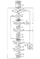
ここで、上記破砕装置3、コンベア6、及び走行体5は、この自走式破砕機1に備えられる油圧駆動装置によって駆動される被駆動部材を構成している。図3は、本発明の自走式破砕機の油圧駆動装置の一実施の形態のうち、前記破砕用油圧モータ12に係わる要部構成を表す油圧回路図である。
【0035】
この図3において、油圧駆動装置は、上記エンジン16と、このエンジン16によって駆動される可変容量型の上記第1油圧ポンプ17及び上記第2油圧ポンプ18と、同様にエンジン16によって駆動される固定容量型のパイロットポンプ19と、第1及び第2油圧ポンプ17,18から吐出される圧油がそれぞれ供給される前記破砕用油圧モータ12と、第1及び第2油圧ポンプ17,18から前記破砕用油圧モータ12に供給される圧油の流れ(方向及び流量)を制御する第1及び第2コントロールバルブ20,21と、破砕機本体4(例えば前記の運転席16内)に設けられ、破砕装置3、コンベア6等の始動・停止を操作者が指示入力して操作するための操作盤22とを有している。
【0036】
破砕用油圧モータ12は、前述のように破砕装置3動作用の駆動力を発生するものであり、斜板12aの傾転角が変化することにより容量が変化可能な可変容量型のモータとなっている。この斜板12aの傾転角は、油圧駆動のシリンダ装置23によって駆動調整される。すなわち、シリンダ装置23は、斜板12aに連結されたロッド部23aと、ロッド部23aを図3中左側方向に付勢するばね部材23bと、ボトム側油室23cとを備えており、後述の容量調整用パイロットライン37を介しボトム側油室23cに圧油が導入されるとばね部材23bの付勢力に抗して斜板12aの傾転角を小さくし、ボトム側油室23cに圧油が導入されなくなるとばね部材23bの付勢力によって斜板12aの傾転角を大きくするようになっている。
【0037】
第1及び第2コントロールバルブ20,21はともに3位置切換弁であり、第1コントロールバルブ20は第1油圧ポンプ17の吐出管路24に設けられて第1油圧ポンプ17から破砕用油圧モータ12へ供給される圧油を制御し、第2コントロールバルブ21は第2油圧ポンプ18の吐出管路25に設けられて第2油圧ポンプ18から破砕用油圧モータ12へ供給される圧油を制御するようになっている。なおこのとき、第1油圧ポンプ吐出管路24に第1コントロールバルブ20の下流側で接続される正転側圧油供給管路26(又は逆転側圧油供給管路27)と、第2油圧ポンプ吐出管路25に第2コントロールバルブ21の下流側で接続される正転側圧油供給管路28(又は逆転側圧油供給管路29)とは、下流側で合流し、1つの正転側圧油供給管路30(又は逆転側圧油供給管路31)となって圧油を破砕用油圧モータ12へと圧油を導くようになっている。
【0038】
上記第1及び第2コントロールバルブ20,21はそれぞれ、両端にパイロット駆動部20a,20b及び21a,21bを備え、パイロット圧を用いて操作されるセンターバイパス型のパイロット操作弁であり、前記パイロットポンプ19で発生された圧力を用いて切換弁32で生成されたパイロット圧により操作される。この切換弁32は、両端にソレノイド駆動部32a,32bを備えた電磁切換弁である。ソレノイド駆動部32a,32bには、コントローラ33からの駆動制御信号Sa(破砕用油圧モータ12の正転方向への駆動に対応),Sb(破砕用油圧モータ12の逆転方向への駆動に対応)で駆動されるソレノイドがそれぞれ設けられており、切換弁32はその正転制御信号Sa又は逆転制御信号Sbの入力に応じて切り換えられるようになっている。
【0039】
すなわち、コントローラ33から切換弁ソレノイド駆動部32aに正転制御信号Saが出力されると、切換弁32が図3中右側の切換位置32Aに切り換えられる。これにより、パイロットポンプ19からの圧油がその吐出管路34及び切換位置32Aを経て切換弁32下流側の正転用パイロットライン35a〜cへと導かれ、これらを介し、正転用パイロット圧として第1コントロールバルブ20のパイロット駆動部20a及び第2コントロールバルブ21のパイロット駆動部21aへと導かれる。また同時に、逆転用パイロットライン36a〜c(詳細は後述)及び上記容量調整用パイロットライン37(同)内の圧力はタンク管路38を介しすべてタンク39の圧力(タンク圧)と等しくなる。これにより、第1コントロールバルブ20は図3中右側の切換位置20Aに切り換えられ、第1油圧ポンプ17からの圧油が吐出管路24、第1コントロールバルブ切換位置20A、及び正転側圧油供給管路26を介して正転側圧油供給管路30に導入されるが、このとき同時に、第2コントロールバルブ21も図3中右側の切換位置21Aに切り換えられ、第2油圧ポンプ18からの圧油が吐出管路25、第2コントロールバルブ切換位置21A、及び正転側圧油供給管路28を介して正転側圧油供給管路39に導入され、正転側圧油供給管路30において前述の第1油圧ポンプ17からの圧油と合流する。この合流した2ポンプ分の圧油が破砕用油圧モータ12に供給され、破砕用油圧モータ12が正転方向(順方向)に駆動される。
【0040】
一方、コントローラ33から切換弁ソレノイド駆動部32bに逆転制御信号Sbが出力されると、切換弁32が図3中左側の切換位置32Bに切り換えられる。これにより、パイロットポンプ19からの圧油がその吐出管路34及び切換位置32Bを経て切換弁32下流側の逆転用パイロットライン36a〜cへと導かれ、これらを介し、逆転用パイロット圧として第1コントロールバルブ20のパイロット駆動部20b及び第2コントロールバルブ21のパイロット駆動部21bへと導かれ、同時に前記正転用パイロットライン35a〜c内の圧力はタンク管路38を介しすべてタンク39の圧力と等しくなる。これにより、第1コントロールバルブ20は図3中左側の切換位置20Bに切り換えられ、第1油圧ポンプ17からの圧油が吐出管路24、第1コントロールバルブ切換位置20B、及び逆転側圧油供給管路27を介して逆転側圧油供給管路31に導入され、同時に第2油圧ポンプ18からの圧油が吐出管路25、第2コントロールバルブ切換位置21B、及び逆転側圧油供給管路29を介し逆転側圧油供給管路31に導入され、第1油圧ポンプ17からの圧油と合流する。この2ポンプ分の圧油が破砕用油圧モータ12に供給されて逆転方向(逆方向)に駆動される。
【0041】
またこのとき、前記の逆転用パイロットライン36aから分岐して上記容量調整用パイロットライン37が接続されており、切換弁32が図3中左側の切換位置32Bに切り換えられて生成された前記逆転用パイロット圧は、逆転用パイロットライン36aから前記容量調整用パイロットライン37へと導入され、前記シリンダ装置ボトム側油室23cへと導かれる。これにより、前述のようにシリンダ装置23が破砕用油圧モータ12の斜板12aの傾転角を小さくし、破砕用油圧モータ12の容量を小さくするようになっている。
【0042】
また、駆動信号Sa,Sbのいずれもが切換弁ソレノイド駆動部32a,32bへ出力されない場合は、切換弁32はばね32c,32dの付勢力で図3に示す中立位置32Cに復帰し、正転用パイロットライン35a〜c及び逆転用パイロットライン36a〜c及び容量調整用パイロットライン37内の圧力はタンク管路38を介しすべてタンク39の圧力(タンク圧)と等しくなる。その結果、第1コントロールバルブ20がばね20c,20dの付勢力で図3中に示す中立位置20Cに復帰するとともに、第2コントロールバルブ21もばね21c,21dの付勢力で図3中に示す中立位置21Cに復帰し、第1及び第2油圧ポンプ17,18の吐出油はタンク管路40,41を介しタンクへ戻る。すなわち、正転側圧油供給管路30及び逆転側圧油供給管路31のいずれにも圧油は供給されなくなるため、破砕用油圧モータ9はそのときの状態のままで停止する。
【0043】
なお、第1及び第2油圧ポンプ17,18及びパイロットポンプ19の前記吐出管路24,25,34から分岐した管路42,43,44には、リリーフ弁45,46,47がそれぞれ設けられており、第1及び第2油圧ポンプ17,18及びパイロットポンプ19の吐出圧の最大値をそれぞれ制限するリリーフ圧の値を、それぞれに備えられたばね45a,46a,47aの付勢力で設定するようになっている。
【0044】
また、第1及び第2油圧ポンプ17,18は、特に詳細な説明を省略するが、レギュレータ装置(図示せず)によってそれぞれの吐出圧力が上昇するに従って吐出流量の最大値が小さく制限され、油圧ポンプ17,18の入力馬力(入力トルク)がエンジン16の出力馬力(出力トルク)以下になるように油圧ポンプ17,18の斜板17a,18aの傾転が制御されるようになっている(公知の入力トルク制限制御又は馬力制御)。
【0045】
また、前述した正転側圧油供給管路30及び逆転側圧油供給管路31には、それらの圧力を検出する圧力センサ48,49がそれぞれ設けられており、これら圧力センサ48,49は対応する検出信号P1,P2をコントローラ33へ出力するようになっている。
【0046】
前記の操作盤22には、破砕装置3を正転方向に起動させるための起動スイッチ(図示せず)と、破砕装置3を停止させるための停止スイッチ(同)とが備えられている。操作者が上記操作盤22の各スイッチの操作を行うと、その操作信号が前記のコントローラ33に入力される。コントローラ33は、操作盤22からの操作信号に基づき、前述した切換弁32へ前記正転制御信号Sa又は前記逆転制御信号Sbを生成し、対応する切換弁ソレノイド駆動部32a,32bにそれらを出力するようになっている。
【0047】
ここで、本実施の形態の要部は、破砕装置3の正転動作から逆転動作へ移行するとき、破砕用油圧モータ12の傾転角を小さくすることにより、従来技術よりも逆転動作に必要な時間を短縮することにある。この機能に関するコントローラ33の制御内容を、その制御フローである図4を参照しつつ説明する。
【0048】
図4において、前述した操作盤22の起動スイッチが押されると、コントローラ33はこのフローを開始する。まずステップ10で、破砕装置3が過負荷状態かどうかを識別するためのフラグ、過負荷状態の継続時間をカウントするための計算子T、及び逆転動作の継続時間をカウントするための計算子T′をそれぞれ0にクリアする。
【0049】
次にステップ20で、破砕装置(シュレッダ)3の停止が指示されたかどうかを判定する。具体的には、前述の操作盤22の停止スイッチが押されたかどうかを判定する。停止スイッチが押されていれば、この判定が満たされ、後述のステップ130に移って直ちに破砕装置3を停止する。停止スイッチが押されていなければこの判定が満たされず、ステップ30へ移る。
【0050】
ステップ30では、フラグが前記した破砕装置3の過負荷状態を示す1であるかどうかを判定する。過負荷状態であればフラグが1となっており(後述する)判定が満たされるため、後述のステップ110に移って直ちに破砕装置3を逆転どうさ方向へと駆動する(後述)。過負荷状態でなければフラグは0であるため、この判定が満たされず、ステップ40へ移る。
【0051】
ステップ40では、破砕装置3を正転方向へ駆動する。すなわち、前記切換弁32のソレノイド駆動部32aへ正転制御信号Saを出力するとともに、もしソレノイド駆動部32bに逆転制御信号Sbが出力されていたらそれを停止し、切換弁32を切換位置32Aに切り換え、これによって第1及び第2コントロールバルブ20,21を切換位置20A,21Aに切り換え、第1及び第2油圧ポンプ17,18からの圧油を正転側圧油供給管路30を介し破砕用油圧モータ12に供給して破砕装置3を正転方向に駆動する。
【0052】
その後、ステップ50に移り、正転側圧油供給管路30に設けた前記圧力センサ48の検出信号P1を入力し、P1が予め定められた所定のしきい値P10(=破砕装置3の停止や破損を防止できるように適宜設定記憶させておく)より大きいかどうかを判定する。P1≦P10であれば判定が満たされず破砕装置3は高負荷状態ではないとみなされ、ステップ60で前記時間計算子T=0にクリアした後ステップ20へ戻る。P1>P10であれば判定が満たされて破砕装置3の高負荷状態とみなされ、ステップ70で前記時間計算子Tに1を加えた後、ステップ80へと移る。
【0053】
ステップ80では、Tが予め定められた所定のしきい値T1(=過渡的・一時的な高負荷状態であるか継続的な過負荷状態であるかを判定するために適宜設定記憶させておく)より大きいかどうかを判定する。T≦T1であれば判定が満たされずステップ20へ戻って上記ステップ20〜80を繰り返す。この繰り返している間に高負荷状態でなくなりP1≦P10となればステップ50からステップ60に移って前記時間計算子Tは再びクリアされるが、繰り返している間高負荷状態であるP1>P10が継続してついにT>T1となったら、ステップ80の判定が満たされて破砕装置3は過負荷状態であるとみなされ、ステップ90へと移る。
【0054】
ステップ90では、時間計算子T=0にクリアする。その後、ステップ100で前記フラグを過負荷状態であることを示す1にし、ステップ110へと移る。
【0055】
ステップ110では、破砕装置3を逆転方向へ駆動する。すなわち、前記切換弁32のソレノイド駆動部32bへ逆転制御信号Sbを出力するとともに、もしソレノイド駆動部32aに逆転制御信号Saが出力されていたらそれを停止し、切換弁32を切換位置32Bに切り換える。これによって第1及び第2コントロールバルブ20,21を切換位置20B,21Bに切り換え、第1及び第2油圧ポンプ17,18からの圧油を逆転側圧油供給管路31を介し破砕用油圧モータ12に供給して破砕装置3を逆転方向に駆動する。同時に、容量調整用パイロットライン37を介してシリンダ装置23に逆転用パイロット圧を作用させ、油圧モータ12の斜板12aの傾転角を小さくする。
【0056】
その後、ステップ120に移り、逆転側圧油供給管路30に設けた前記圧力センサ49の検出信号P2を入力し、P2が予め定められた所定のしきい値P20(=破砕装置3の停止や破損を防止できるように適宜設定記憶させておく)より大きいかどうかを判定する。P2≦P20であれば判定が満たされず、これ以上の動作は破砕装置3の破損等を招く可能性がある好ましくない状態であるとみなされ、ステップに移って破砕装置(シュレッダ)3を停止させる。すなわち、切換弁32のソレノイド駆動部32a及びソレノイド駆動部32bの制御信号Sa,Sbをともに停止して図3に示す中立位置に復帰させ、破砕用油圧モータ12を停止させ、このフローを終了する。
【0057】
ステップ120においてP2>P20であれば判定が満たされて破砕装置3が破損する可能性のある好ましくない状態ではないとみなされ、ステップ140で前記時間計算子T′に1を加えた後、ステップ150へと移る。
【0058】
ステップ150では、T′が予め定められた所定のしきい値T2(=詰まった被破砕物・異物がカッタ3b,3b間から脱出するのに十分なように適宜設定記憶させておく)より大きいかどうかを判定する。T′≦T2であれば判定が満たされずステップ20へ戻って上記ステップ20〜150を繰り返す。但しこのときフラグが過負荷状態を示す1となっていることから、ステップ20→ステップ30→ステップ110→ステップ120〜150を繰り返すこととなる。この繰り返している間にP2>P20となればステップ120からステップ130に移って直ちに破砕装置3が停止されるが、繰り返している間P2≦P20が継続してついにT′>T2となったら、ステップ150の判定が満たされて破砕装置3は十分な時間だけ逆転をしたとみなされ、ステップ160へと移る。
【0059】
ステップ160では、前記時間計算子T′=0にクリアする。その後、ステップ170に移ってフラグを過負荷状態でない0にクリアし、ステップ20へ戻る。その後は、同様の手順を繰り返す。
【0060】
なお、上記において、第1及び第2コントロールバルブ20,21が特許請求の範囲記載の破砕用コントロールバルブを構成し、正転側圧油供給管路26,28,30が破砕用油圧モータが正転動作する側の圧油供給管路を構成し、圧力センサ48が、その圧油供給管路に接続された圧力センサを構成するとともに、破砕用油圧モータの正転動作時における負荷を検出する正転負荷検出手段をも構成する。
【0061】
また、容量調整用パイロットライン37は、逆転用パイロット圧をモータ容量調整手段へ導く容量調整用パイロット管路を構成する。
【0062】
さらに、シリンダ装置23は、破砕用油圧モータの容量を変化させるモータ容量調整手段を構成する。また、コントローラ33は、破砕用油圧モータが正転動作するか逆転動作するかに応じて、対応する制御信号を出力する制御信号出力手段を構成し、パイロットポンプ19、吐出管路34、及び切換弁32は、制御信号に応じたパイロット圧を生成し出力するパイロット圧生成手段を構成し、これらコントローラ33、パイロットポンプ19、吐出管路34、切換弁32、及びパイロットライン36a,37が、破砕用油圧モータが正転動作するか逆転動作するかに応じ、モータ容量調整手段による調整動作を制御する調整動作制御手段を構成する。そして、コントローラ33、パイロットポンプ19、吐出管路34、切換弁32、パイロットライン36a,37、及びシリンダ装置23が、破砕用油圧モータが正転動作するか逆転動作するかに応じ、破砕用油圧モータの容量を切り換えて制御する制御手段を構成する。
【0063】
次に、本実施の形態の動作及び作用を以下に説明する。
【0064】
上記構成の自走式破砕機1において、破砕作業時には、操作者は、操作盤22の起動スイッチ(図示せず)を押す。これにより、図4に示したフローのステップ10、ステップ20、ステップ30を経て、ステップ40においてコントローラ33から切換弁ソレノイド駆動部32aに正転制御信号Saが出力されて、第1及び第2油圧ポンプ17,18からの圧油が正転側供給管路26,28,30を介して破砕用油圧モータ12に供給され、破砕装置3が正転方向に起動される。
【0065】
そして、例えば油圧ショベルのバケットでホッパ2に岩石・建設廃材等を投入すると、ホッパ2で受け入れられた岩石・建設廃材等が破砕装置3へと導かれ、破砕装置3で所定の大きさに破砕される。破砕された破砕物は、破砕装置3下部の空間からコンベア6上に落下して運搬され、大きさがほぼ揃えられて、最終的に破砕機1の後部(図1中右端部)から搬出される。
【0066】
このとき、ホッパ2に投入した岩石・建設廃材等に破砕装置3で破砕困難なものや破砕不可能な異物(以下、異物等という)が混入していた場合には、それらが破砕装置3のカッタ3b,3b間に噛み込まれようとするときに破砕用油圧モータ12の負荷が大きくなり、正転側供給管路30の圧力を検出する圧力センサ48の検出信号P1が前記P10よりも大きくなる。これにより図4のフローのステップ50の判定が満たされてステップ70→ステップ80へと進み、この状態が所定の時間継続するとステップ80の判定が満たされてステップ90、ステップ100を経てステップ110においてコントローラ33から切換弁ソレノイド駆動部32bに逆転制御信号Sbが出力されて、第1及び第2油圧ポンプ17,18からの圧油が逆転側供給管路27,29,31を介して破砕用油圧モータ12に供給され、破砕装置3が逆転方向に起動される。これにより、破砕装置3の刃物3b,3bが逆方向に回転し、いったん噛み込んだ異物等を上方へ押し出すことができる。本実施の形態においては、この逆転動作時には破砕力をほとんど必要としないことに着目し、容量調整用パイロットライン37を介しシリンダ装置23に逆転用パイロット圧を供給することで、正転動作時に比べて破砕用油圧モータ12の容量を小さくしている。これによって、逆転動作時における破砕用油圧モータ12の容量を正転動作時と同一とする場合に比べ、逆転動作時において破砕用油圧モータ12をより高速で回転させることができる。
【0067】
投入された異物等が破砕不可能な異物であった場合等ではそれがカッタ3b,3b間に引っかかる等によってこの逆転動作時にも破砕用油圧モータ12の負荷が大きくなるため、逆転側供給管路31の圧力を検出する圧力センサ49の検出信号P2が前記P20よりも大きくなり、ステップ130で破砕装置3は停止する。
【0068】
投入された異物等が破砕不可能ではないがたまたま破砕能力を上回る大きさ又は量の被破砕物であった場合等では、上記逆転動作によってその投入被破砕物がほぐされてより破砕されやすくなるので、逆転動作時には破砕用油圧モータ12の負荷は大きくならない。これによりステップ120の判定が満たされてステップ140→ステップ150へと進み、この状態が所定の時間継続するとステップ50の判定が満たされてステップ160、ステップ170、ステップ20、ステップ30を経てステップ40において再び破砕用油圧モータ12の正転駆動が行われる。
【0069】
このようにして、正転動作や、正転→逆転→正転という動作を繰り返しながら、破砕作業を行っていき、破砕作業が終了したら、操作者が操作盤22の停止スイッチ(図示せず)を押すことにより、ステップ20からステップ130へ移って破砕装置3が停止する。
【0070】
以上説明したように、本実施の形態によれば、破砕装置3の逆転動作時において、逆転動作時における破砕用油圧モータ12の容量を正転動作時と同一とする場合に比べ、破砕用油圧モータ12をより高速で回転させることができる。したがって、逆転動作に要する時間を低減し、破砕作業全体に要する時間を短縮できるので、作業効率の向上を図ることができる。
【0071】
なお、上記本発明の一実施の形態においては、図3に示したように、正転動作時にも逆転動作時にも破砕用油圧モータ12に2つのポンプ17,18からの圧油を合流させて供給したが、これに限られず、逆転動作時には1つのポンプだけから圧油を供給するようにしても良い。そのような変形例を以下に説明する。
【0072】
図5は、この油圧駆動装置の変形例の要部構成を表す油圧回路図であり、上記本発明の一実施の形態のおける図3に相当する図である。図3と同等の部分には同一の符号を付し、説明を省略する。
【0073】
図5において、この油圧駆動装置では、図3における3位置切換弁の第2コントロールバルブ21に代え、2位置切換弁である第2コントロールバルブ121を設けている。この第2コントロールバルブ121は、上記コントロールバルブ21の図3中左側の切換位置21Bを省略した構造となっており、コントローラ33から切換弁ソレノイド駆動部32aに正転制御信号Saが出力され、切換弁32が図3中右側の切換位置32Aに切り換えられたときは、上記本発明の一実施の形態の第2コントロールバルブ21同様、正転用パイロットライン35a,35cを介した正転用パイロット圧がパイロット駆動部121aへと導かれ、図5中右側の切換位置121Aに切り換えられ、第2油圧ポンプ18からの圧油が吐出管路25、切換位置121A、及び正転側圧油供給管路28を介して正転側圧油供給管路39に導入され、正転側圧油供給管路30において前述の第1油圧ポンプ17からの圧油と合流し、2ポンプ分の圧油が破砕用油圧モータ12に供給される。
【0074】
一方、コントローラ33から切換弁ソレノイド駆動部32bに逆転制御信号Sbが出力されたときは、第2コントロールバルブ121は、ばね121bの付勢力で図5中に示す遮断位置121Bに復帰し、第2油圧ポンプ18の吐出油はタンク管路41を介しタンク39へ戻る。すなわち、逆転側圧油供給管路31には、第1コントロールバルブ20の切換位置20Bを介した第1油圧ポンプ17からの圧油のみが供給されるようになっている。
【0075】
また、駆動信号Sa,Sbのいずれもが出力されない場合は、第2コントロールバルブ121は上記同様の遮断位置121Bとなるとともに、第1コントロールバルブ20は上記本発明の一実施の形態と同様にしてばね20c,20dの付勢力で図3中に示す中立位置20Cに復帰し、正転側圧油供給管路30及び逆転側圧油供給管路31のいずれにも圧油は供給されなくなる。
【0076】
なお、上記において、第2コントロールバルブ121が破砕用コントロールバルブを構成し、コントローラ33、切換弁32、正転用パイロットライン35a〜c、逆転用パイロットライン36a,36b、第1コントロールバルブ20、及び第2コントロールバルブ121が、破砕用油圧モータの正転動作時には2つの油圧ポンプからの圧油を合流させて破砕用油圧モータへ供給するとともに、破砕用油圧モータの逆転動作時には1つの油圧ポンプからの圧油のみを破砕用油圧モータへ供給するように、圧油供給経路を切り換える供給切換手段を構成する。
【0077】
また、正転用パイロットライン35a,35bが正転用パイロット圧を第1コントロールバルブへ導く第1正転用パイロット管路を構成し、正転用パイロットライン35a,35cが正転用パイロット圧を第2コントロールバルブへ導く第2正転用パイロット管路を構成する。また逆転用パイロットライン36a,36bが、逆転用パイロット圧を第1コントロールバルブへ導く逆転用パイロット管路を構成する。また、容量調整用パイロットライン37が、逆転用パイロット圧をシリンダ装置へ導く容量調整用パイロット管路を構成する。
【0078】
また、第1コントロールバルブ20の切換位置20Aが、第1油圧ポンプからの圧油を破砕用油圧モータが正転動作する側の圧油供給管路へ供給する正転用導通位置を構成し、切換位置20Bが、第1油圧ポンプからの圧油を破砕用油圧モータが逆転動作する側の圧油供給管路へ供給する逆転用導通位置を構成する。また第2コントロールバルブ121の切換位置121Aが、正転用パイロット管路から正転用パイロット圧が導入されたときは、第2油圧ポンプからの圧油を破砕用油圧モータが正転動作する側の圧油供給管路へ供給する導通位置を構成し、中立位置121Bが、正転用パイロット圧が導入されないときは、第2油圧ポンプからの圧油を破砕用油圧モータへ供給しない遮断位置を構成する。
【0079】
上記変形例においても、上記本発明の一実施の形態と同様、破砕装置3の逆転動作時において、逆転動作時における破砕用油圧モータ12の容量を正転動作時と同一とする場合に比べ、破砕用油圧モータ12をより高速で回転させることができる。また図5の回路においては、破砕装置3の逆転動作時においてはもともと破砕用油圧モータ12への供給圧油量が1/2となるので破砕用油圧モータ12の逆転動作が正転動作時よりは遅くなるものであるが、逆転動作時における破砕用油圧モータ12の容量を正転動作時よりも小さくすることで、破砕用油圧モータ12の回転速度を増大させ、正転動作時における回転速度との差を縮小したりあるいは正転動作時における回転速度より大きな速度とすることも可能である。
【0080】
また、通常、破砕作業を行わない逆転動作時における圧油供給ポンプ数を正転動作時における圧油供給ポンプ数の半分に減らすことにより、省エネルギ効果を得ることができる。
【0081】
また、上記本発明の一実施の形態においては、操作者は操作盤22から破砕装置3の正転起動及び停止のみを操作可能で、正転中に過負荷状態となった場合に自動的に逆転するのみであったが、これに限られず、操作盤22に逆転指示手段としての逆転スイッチを設け、操作者の意図によって手動で逆転動作ができるようにしてもよい。このような変形例を図6により説明する。
【0082】
図6は、この変形例におけるコントローラ33が実施する制御フローを示すものであり、上記本発明の一実施の形態の図4と異なるのは、ステップ20とステップ30との間にステップ25を設けたことである。すなわち、このステップ25で、操作盤22の上記逆転スイッチが押されたかどうかを判定し、判定が満たされたときは、直ちにステップ110に移って破砕装置3を逆転駆動するようにしている。これにより、破砕装置3が正転方向に動作中のどのタイミングでも、操作者の意志によって随時破砕装置3を逆転することができる。そのときの逆転速度は、上記本発明の一実施の形態で説明したように速めることができることは言うまでもない。
【0083】
さらに、上記本発明の一実施の形態においては、切換弁32からの逆転用パイロット圧を容量調整用パイロットライン37を介し導くことによりシリンダ装置23を駆動したが、これに限られず、他の方法で駆動しても良い。そのような変形例を図7及び図8により説明する。
【0084】
図7は、上記変形例による油圧駆動装置のうち要部構成を表す油圧回路図であり、上記本発明の一実施の形態の図3に相当する図である。図7において、前記パイロットポンプ吐出管路34から分岐して前記シリンダ装置23へ至るパイロットライン50a,50bが設けられ、さらにこれらパイロットライン50a,50bを連通・遮断可能な電磁切換弁51が設けられている。この電磁切換弁51は、前記コントローラ33から前記逆転制御信号Sbがソレノイド駆動部51aに入力されると図7中右側の連通位置51Aに切り換えられてパイロットライン50aからの圧油を逆転用パイロット圧としてパイロットライン50bを介してシリンダ装置23に導き、破砕用油圧モータ12の斜板12aの傾転角を小さくするようになっている。前記コントローラ33から前記逆転制御信号Sbが入力されなくなるとばね51bの付勢力で図7に示す遮断位置51Bに復帰してパイロットライン50aとパイロットライン50bとを遮断するとともに、パイロットライン50bをタンク39に連通させて破砕用油圧モータ斜板12aの傾転角を大きくするようになっている。
【0085】
なお、この変形例の構成においては、パイロットライン50bが、逆転用パイロット圧をモータ容量調整手段(シリンダ装置23)へ導く容量調整用パイロット管路を構成する。また、コントローラ33は、破砕用油圧モータが正転動作するか逆転動作するかに応じて、対応する制御信号を出力する制御信号出力手段を構成し、パイロットポンプ19、吐出管路34、パイロットライン50a、及び電磁切換弁51は、制御信号に応じたパイロット圧を生成し出力するパイロット圧生成手段を構成し、これらコントローラ33、パイロットポンプ19、吐出管路34、パイロットライン50a、電磁切換弁51、及びパイロットライン50bが、破砕用油圧モータが正転動作するか逆転動作するかに応じ、モータ容量調整手段による調整動作を制御する調整動作制御手段を構成する。そして、コントローラ33、パイロットポンプ19、吐出管路34、パイロットライン50a、電磁切換弁51、パイロットライン50b、及びシリンダ装置23が、破砕用油圧モータが正転動作するか逆転動作するかに応じ、破砕用油圧モータの容量を切り換えて制御する制御手段を構成する。
【0086】
本変形例によっても、上記本発明の一実施の形態と同様の効果を得る。なお、図8に示すように、上記変形例の構成を、前述の図5に示した構成に適用してもよい。
【0087】
また、以上においては、逆転時の破砕用油圧モータ12の傾転角は常にあるきまった値としたが、これに限られず、例えば逆転直前の負荷圧力等に応じて可変にしても良いことは言うまでもない。また、上記本発明の一実施の形態においては、停止スイッチを押すことによって正転時にも逆転時にも動作停止することが可能としたが、逆転時には停止できないようにしても良い。
【0088】
さらに、以上においては、破砕装置として2軸せん断機を備えた自走式破砕機を例にとって説明したが、これに限られず、もっと多数の軸を備えたせん断機を備えた自走式破砕機にも適用できることは言うまでもない。要は、略平行に配置された複数の回転軸のそれぞれにカッタを固定し、被破砕物を噛み込んでせん断するせん断式破砕装置を備えた自走式破砕機であれば足りる。さらに、このようなせん断式破砕装置にも限られず、他の破砕装置、例えば、ロール状の回転体に破砕用の刃を取り付けたものを一対としてそれら一対を互いに逆方向へ回転させ、それら回転体の間に岩石・建設廃材等を挟み込んで破砕を行う回転式破砕装置(いわゆるロールクラッシャを含む6軸破砕機等)や、複数個の刃物を備えた打撃板を高速回転させ、この打撃板からの打撃及び反発板との衝突を用いて岩石・建設廃材等を衝撃的に破砕するいわゆるインパクトクラッシャを備えた破砕装置や、動歯を固定歯に対して揺動運動させそれらの間で被破砕物を挟み付けるようにして破砕を行うジョークラッシャを備えた破砕装置や、木材、枝木材、建設廃木等の木材をカッタを備えたロータに投入することにより細片にする木材破砕装置等を備えた自走式破砕機にも適用可能である。これらの場合にも、同様の効果を得ることができる。
【0089】
さらに、以上においては、破砕装置による破砕作業に関連する作業を行う補助機械としてコンベア5のみを備えた自走式破砕機に適用した場合を例にとって説明したが、これに限られない。例えば、作業事情に応じホッパ2に受け入れた岩石・建設廃材等を破砕装置3へと搬送し導くフィーダ4を備えているものや、コンベア5の上方に設けられコンベア5上を運搬中の破砕物に含まれる磁性物を磁気的に吸引除去する磁選機6を備えているものに対し適用しても良い。
【0090】
【発明の効果】
本発明によれば、制御手段で、破砕用油圧モータが正転動作するか逆転動作するかに応じて破砕用油圧モータの容量を切り換えて制御するので、逆転動作時には、例えば正転動作時に比べて破砕用油圧モータの容量を小さくすることができる。これにより、従来構造に比べて逆転動作時において破砕用油圧モータをより高速で回転させることができるので、逆転動作に要する時間を低減し、破砕作業全体に要する時間を短縮できるので、作業効率の向上を図ることができる。
【図面の簡単な説明】
【図1】本発明の適用対象である自走式破砕機の全体構造を表す側面図である。
【図2】図1に示した自走式破砕機の上面図である。
【図3】本発明の自走式破砕機の油圧駆動装置の一実施の形態のうち、破砕用油圧モータに係わる要部構成を表す油圧回路図である。
【図4】図3に示したコントローラで実行する制御フローである。
【図5】逆転動作時に1ポンプのみの圧油供給とする変形例の要部構成を表す油圧回路図である。
【図6】操作者の手動で逆転動作ができるようにした変形例のコントローラで実行する制御フローである。
【図7】逆転用パイロット圧を電磁切換弁を介し導くことによりシリンダ装置を駆動する変形例を示す油圧回路図である。
【図8】図7の構成を図5の構成に応用した場合を示す油圧回路図である。
【符号の説明】
1 自走式破砕機
2 ホッパ
3 破砕装置
12 破砕用油圧モータ
12a 斜板
16 エンジン(原動機)
17 第1油圧ポンプ
18 第2油圧ポンプ
19 パイロットポンプ(油圧源、パイロット圧生成手段、調整動作制御手段、制御手段)
20 第1コントロールバルブ(破砕用コントロールバルブ)
20A 切換位置(正転用導通位置)
20B 切換位置(逆転用導通位置)
21 第2コントロールバルブ(破砕用コントロールバルブ)
23 シリンダ装置(モータ容量調整手段、制御手段)
26 正転側圧油供給管路
28 正転側圧油供給管路
30 正転側圧油供給管路
32 切換弁(パイロット圧生成手段、調整動作制御手段、制御手 段)
33 コントローラ(制御信号出力手段、調整動作制御手段、制御手段)
34 吐出管路(パイロット圧生成手段、調整動作制御手段、制御手段)
35a パイロットライン(第1及び第2正転用パイロット管路)
35b パイロットライン(第1正転用パイロット管路)
35c パイロットライン(第2正転用パイロット管路)
36a パイロットライン(逆転用パイロット管路、調整動作制御手 段、制御手段)
36b パイロットライン(逆転用パイロット管路)
37 パイロットライン(容量調整用パイロット管路、調整動作制御手段、制御手段)
48 圧力センサ(正転負荷検出手段)
50a パイロットライン(パイロット圧生成手段、調整動作制御手段、制御手段)
50b パイロットライン(容量調整用パイロット管路、調整動作制御手段、制御手段)
51 電磁切換弁(パイロット圧生成手段、調整動作制御手段、制御手段)
121 第2コントロールバルブ(破砕用コントロールバルブ)
121A 切換位置(導通位置)
121B 切換位置(遮断位置)[0001]
BACKGROUND OF THE INVENTION
The present invention relates to a hydraulic drive device for a self-propelled crusher provided with a crushing device for crushing a material to be crushed, such as a roll crusher or a shredder, and more specifically, a hydraulic drive for a self-propelled crusher capable of improving work efficiency. It relates to the device.
[0002]
[Prior art]
The crusher transports various types of rocks, construction waste materials, industrial waste, natural stones, etc. generated at construction sites, such as concrete lumps delivered at the time of building demolition and asphalt lumps discharged at road repair It is crushed to a predetermined size at the work site before. In such a crusher, a self-propelled crusher has already been proposed that makes the crusher self-propelled and has mobility based on the background of difficulty in securing a site for the crushing plant or dispersion of the site. .
[0003]
This self-propelled crusher includes a traveling body having left and right endless track tracks, a crushing device provided on the upper part thereof, and a conveyor provided on the lower side thereof. The material to be crushed put into the hopper is crushed to a predetermined size by the crushing device, and then the crushed material falls on the conveyor from the space below the crushing device and is transported. And is carried out from the front part or the rear part of the crusher.
[0004]
At this time, the endless track crawler, the crushing device, and the conveyor are driven by hydraulic actuators corresponding thereto. That is, a hydraulic drive device for a self-propelled crusher including these hydraulic actuators is driven by, for example, at least one variable displacement hydraulic pump driven by one prime mover and pressure oil discharged from the hydraulic pump. A traveling hydraulic motor, a crushing hydraulic motor, and a conveyor hydraulic motor that respectively drive the endless track crawler, the crushing device, and the conveyor, and the direction and flow rate of the pressure oil supplied to the hydraulic motor from the hydraulic pump. The pressure oil discharged from the hydraulic pump is supplied to each hydraulic motor via each control valve.
[0005]
By the way, several types of the crushing apparatus have been proposed. For example, a cutter is fixed to each of a plurality of rotation shafts arranged substantially in parallel, and is thinly sheared so as to bite the object to be crushed. A rotating crusher (such as a biaxial shearing machine including a so-called shredder) or a roll-shaped rotating body with a crushing blade (bit) attached thereto is rotated as a pair, and the rotating body is rotated in the opposite direction. A rotary crushing device (such as a 6-axis crusher including a roll crusher) that crushes the object to be crushed in between, or a moving tooth that swings with respect to a fixed tooth to sandwich the object to be crushed between them In this way, a crushing device equipped with a jaw crusher for crushing and a striking plate equipped with a plurality of blades are rotated at high speed, and the shredded material is collided using the impact from the striking plate and the impact plate. To crushing, crushing device and provided with a so-called impact crusher, timber crushing apparatus or the like to strip the by injecting the rotor with wood, branches wood cutter wood such as construction waste wood.
[0006]
Since these various crushing apparatuses have different optimum objects as the objects to be crushed due to their performance, it is usually appropriate to select which crushing apparatus to use according to the type of objects to be crushed. It is. Here, during the crushing operation as described above, if an object to be crushed in a size or amount exceeding the crushing capacity of the crushing apparatus or a foreign object that cannot be crushed is charged, the crushing apparatus is clogged with the object to be crushed. There is a possibility that the crushing device will be stopped or damaged.
[0007]
Therefore, in order to cope with such a problem, for example, as described in JP-A-8-24704, a variable displacement type crushing device that drives the crushing device with pressure oil discharged from at least one hydraulic pump. In a hydraulic drive device of a self-propelled crusher having a hydraulic motor, when a forward load detecting means for detecting a load during the forward operation of the crushing hydraulic motor is provided, and the detected load exceeds a predetermined value The crushing hydraulic motor is increased in tilt angle to increase the crushing force to increase the crushing force, enabling crushing of objects to be crushed that are difficult to crush. In such a case, a configuration has been proposed in which the crushing hydraulic motor is reversed (reversely rotated) on the assumption that it is an overload state in which a non-crushable material or foreign matter is introduced.
[0008]
In addition, as described above, in the shearing crushing device and the rotary crushing device, a method of shearing or crushing the object to be crushed by the cooperative work with the adjacent cutter or blade by rotating the cutter or blade around the rotation axis. When an object that cannot be crushed or a foreign object is caught between adjacent cutters and blades, it can be escaped immediately by reversing it. Therefore, although not clearly shown in the above-mentioned known example, the above configuration is considered to be particularly suitable for a self-propelled crusher equipped with a shearing crushing device or a rotary crushing device. .
[0009]
[Problems to be solved by the invention]
In the above prior art, when non-crushable material or foreign matter is thrown in, the crushing hydraulic motor is reversed so that the non-crushable material or foreign material is released from the biting state to prevent the crushing device from being stopped or damaged. To do.
[0010]
However, this conventional technique has the following problems.
In other words, the crushing hydraulic motor has the same tilt angle during forward rotation and reverse rotation, and the crushing hydraulic motor is reversely rotated from the state in which the tilting angle of the crushing hydraulic motor is increased during forward rotation and high load. Therefore, the crushing hydraulic motor reverses with a large tilt angle (= low speed and high pressure state). However, the crushing operation is not normally performed during the reverse rotation except for a special crushing device configured to perform the crushing at another location even during the reverse rotation. In other words, although the crushing force is almost unnecessary at the time of reverse rotation, the above-mentioned conventional technique wastes low-speed and high-pressure operation and requires a long reverse rotation time. For this reason, the time required for the entire crushing operation is extended, resulting in a decrease in work efficiency.
[0011]
The present invention has been made in view of the above problems, and an object of the present invention is to provide a hydraulic drive device for a self-propelled crusher capable of improving work efficiency by shortening the reverse operation time. .
[0012]
[Means for Solving the Problems]
(1) In order to achieve the above object, the present invention is also provided in a self-propelled crusher that crushes an object to be crushed by a crushing device, and the crushing device is operated by pressure oil discharged from at least one hydraulic pump. In a hydraulic drive device of a self-propelled crusher having a variable displacement crushing hydraulic motor to be driven, the capacity of the crushing hydraulic motor is switched depending on whether the crushing hydraulic motor performs forward rotation or reverse rotation. And control means for controlling.
[0013]
Thereby, the capacity | capacitance of the hydraulic motor for crushing can be made small at the time of reverse rotation operation which requires little crushing force compared with the time of forward rotation operation, for example. Thus, the crushing hydraulic motor can be rotated at a higher speed during the reverse rotation operation than when the capacity of the crushing hydraulic motor during the reverse rotation operation is the same as that during the normal rotation operation. Accordingly, the time required for the reverse operation can be reduced and the time required for the entire crushing operation can be shortened, so that the work efficiency can be improved.
[0014]
(2) In the above (1), preferably, the control means reduces the capacity of the crushing hydraulic motor during the reverse rotation operation compared to during the normal rotation operation.
[0015]
(3) In the above (1), and preferably, the control means determines whether the capacity of the crushing hydraulic motor is changed and whether the crushing hydraulic motor is rotated forward or backward. And adjusting operation control means for controlling the adjusting operation by the motor capacity adjusting means.
[0016]
(4) In the above (3), more preferably, the adjustment operation control unit outputs a control signal corresponding to the crushing hydraulic motor according to whether the crushing hydraulic motor performs a normal rotation operation or a reverse operation. And a pilot pressure generating means for generating and outputting a pilot pressure in accordance with the control signal, and a capacity adjusting pilot pipe for guiding the pilot pressure to the motor capacity adjusting means. The capacity of the crushing hydraulic motor is changed according to the pilot pressure guided through the capacity adjusting pilot pipe.
[0017]
(5) In the above (1) or (2), and preferably, it further includes a forward rotation load detecting means for detecting a load during the forward rotation operation of the crushing hydraulic motor, and the control means includes the forward rotation detecting means. The capacity of the crushing hydraulic motor is controlled according to the detected load of the rolling load means.
[0018]
Thereby, for example, when the load during normal rotation operation of the crushing hydraulic motor detected by the normal load detecting means is increased, even when the crushing hydraulic motor is automatically reversely operated, Correspondingly, the capacity of the crushing hydraulic motor can be reduced immediately.
[0019]
(6) In the above (1) or (2), and preferably, it further includes reverse rotation instruction means for an operator to input the reverse rotation operation of the crushing hydraulic motor, and the control means includes the reverse rotation instruction means The capacity of the crushing hydraulic motor is controlled in accordance with an instruction input from.
[0020]
Thereby, even if it is a case where the hydraulic motor for crushing is reversely operated by an operator's manual operation, the capacity | capacitance of the hydraulic motor for crushing can be made small immediately corresponding to it, for example.
[0021]
(7) In the above (1) or (2), and preferably, at least two of the hydraulic pumps are provided, and pressure oil from the two hydraulic pumps is supplied during the forward operation of the crushing hydraulic motor. Supply that switches the pressure oil supply path so that only the pressure oil from one hydraulic pump is supplied to the crushing hydraulic motor during reverse rotation of the crushing hydraulic motor while being merged and supplied to the crushing hydraulic motor Switching means is provided.
[0022]
Usually, an energy saving effect can be obtained by reducing the number of pressure oil supply pumps during the reverse operation without the crushing operation to half the number of pressure oil supply pumps during the normal operation.
[0023]
(8) In any one of the above (1) to (7), preferably, the crushing device fixes a cutter to each of a plurality of rotating shafts arranged substantially in parallel, and bites an object to be crushed. A shearing crushing device that shears and shears, or a substantially roll-shaped rotating body with a blade for crushing as a pair, the pair is rotated in opposite directions, and the object to be crushed is placed between the rotating bodies It is a rotary crushing device that crushes as if biting.
[0024]
(9) In order to achieve the above object, the present invention provides a first hydraulic pressure and a second hydraulic pressure that are provided in a self-propelled crusher that crushes a material to be crushed from a hopper with a crushing device and is driven by a prime mover. A variable displacement type crushing hydraulic motor that includes a pump, a swash plate whose tilt angle can be changed, and that drives the crushing device with pressure oil discharged from the first and second hydraulic pumps; In a hydraulic drive device for a self-propelled crusher having a hydraulic pilot type first control valve and a second control valve for controlling the direction and flow rate of pressure oil supplied from a second hydraulic pump to the crushing hydraulic motor, respectively. A pressure sensor connected to a pressure oil supply line on a side where the crushing hydraulic motor performs normal rotation, and the crushing hydraulic motor is operated in the normal operation or reverse operation according to the detected pressure of the pressure sensor. And a controller that outputs a forward rotation control signal or a reverse rotation control signal for switching, and a forward rotation pilot pressure or a reverse rotation pilot pressure that is switched according to the forward rotation control signal or the reverse rotation control signal, using pressure from a hydraulic pressure source. A switching valve for generating and outputting the forward rotation pilot pressure, a first forward rotation pilot line and a second forward rotation pilot line for guiding the forward rotation pilot pressure to the first control valve and the second control valve, respectively, and the reverse rotation pilot A reverse pilot line for guiding pressure to the first control valve, a hydraulically driven cylinder device for driving and adjusting a tilt angle of the swash plate of the crushing hydraulic motor, and the reverse pilot pressure to the cylinder device A capacity adjustment pilot line that guides the first control valve from the forward rotation pilot line. When the pilot pressure is introduced, the pressure oil from the first hydraulic pump is switched to the forward rotation conducting position for supplying the pressure oil to the pressure oil supply line on the side where the crushing hydraulic motor performs forward rotation, and the reverse rotation When the reverse pilot pressure is introduced from the pilot pipe, the pressure oil from the first hydraulic pump is supplied to the reverse conduction position for supplying the pressure oil supply line on the side where the crushing hydraulic motor is reversely operated. When the normal control pilot pressure is introduced from the normal pilot line, the second control valve is operated so that the crushing hydraulic motor rotates the pressure oil from the second hydraulic pump. When switched to the conduction position for supplying the pressure oil supply line and the forward pilot pressure is not introduced, the pressure oil from the second hydraulic pump is not supplied to the crushing hydraulic motor. Switch to the disconnect position.
[0025]
DETAILED DESCRIPTION OF THE INVENTION
Hereinafter, an embodiment of the present invention will be described with reference to the drawings.
FIG. 1 is a side view showing the overall structure of a self-propelled crusher to which the present invention is applied, and FIG. 2 is a top view of the self-propelled crusher shown in FIG.
[0026]
1 and 2, the self-propelled
[0027]
The traveling
[0028]
As shown in FIGS. 1 and 2, the crushing
[0029]
This crushing
[0030]
The
[0031]
A
[0032]
The
[0033]
In addition, a driver's
[0034]
Here, the crushing
[0035]
In FIG. 3, the hydraulic drive device includes the
[0036]
The crushing
[0037]
Both the first and
[0038]
The first and
[0039]
That is, when the forward rotation control signal Sa is output from the
[0040]
On the other hand, when the reverse rotation control signal Sb is output from the
[0041]
At this time, the capacity
[0042]
When neither of the drive signals Sa and Sb is output to the switching valve
[0043]
[0044]
The first and second
[0045]
Further, the aforementioned forward pressure
[0046]
The operation panel 22 includes a start switch (not shown) for starting the crushing
[0047]
Here, the main part of the present embodiment is necessary for the reverse rotation operation as compared with the prior art by reducing the tilt angle of the crushing
[0048]
In FIG. 4, when the start switch of the operation panel 22 described above is pressed, the
[0049]
Next, at
[0050]
In
[0051]
In
[0052]
Thereafter, the process proceeds to step 50, where the detection signal P1 of the
[0053]
In
[0054]
In
[0055]
In step 110, the crushing
[0056]
Thereafter, the routine proceeds to step 120 where the detection signal P2 of the
[0057]
If P2> P20 in
[0058]
In
[0059]
In
[0060]
In the above description, the first and
[0061]
Further, the capacity
[0062]
Further, the
[0063]
Next, the operation and action of the present embodiment will be described below.
[0064]
In the self-propelled
[0065]
For example, when rocks, construction waste, etc. are put into the
[0066]
At this time, if rocks, construction waste, or the like put into the
[0067]
When the introduced foreign matter or the like is a foreign matter that cannot be crushed, the load on the crushing
[0068]
In the case where the input foreign matter is not impossible to be crushed but happens to be a crushed object with a size or quantity exceeding the crushing capacity, the reversing operation loosens the input crushed object and makes it easier to be crushed. Therefore, the load on the crushing
[0069]
In this way, the crushing operation is performed while repeating the forward rotation operation and the forward rotation → reverse rotation → forward rotation, and when the crushing operation is completed, the operator switches the stop switch (not shown) on the operation panel 22. By pressing, the process proceeds from
[0070]
As described above, according to the present embodiment, when the crushing
[0071]
In the embodiment of the present invention, as shown in FIG. 3, the crushing
[0072]
FIG. 5 is a hydraulic circuit diagram showing a main configuration of a modified example of the hydraulic drive device, and corresponds to FIG. 3 according to the embodiment of the present invention. Parts equivalent to those in FIG. 3 are denoted by the same reference numerals, and description thereof is omitted.
[0073]
5, this hydraulic drive apparatus is provided with a
[0074]
On the other hand, when the reverse rotation control signal Sb is output from the
[0075]
When neither of the drive signals Sa and Sb is output, the
[0076]
In the above, the
[0077]
Further, the forward
[0078]
Further, the
[0079]
Also in the modified example, as in the above-described embodiment of the present invention, compared to the case where the capacity of the crushing
[0080]
Further, an energy saving effect can be obtained by reducing the number of pressure oil supply pumps during the reverse rotation operation without performing the crushing operation to half of the number of pressure oil supply pumps during the normal rotation operation.
[0081]
In the above-described embodiment of the present invention, the operator can operate only the normal rotation start and stop of the crushing
[0082]
FIG. 6 shows a control flow executed by the
[0083]
Furthermore, in the above-described embodiment of the present invention, the
[0084]
FIG. 7 is a hydraulic circuit diagram showing a main configuration of the hydraulic drive device according to the modified example, and corresponds to FIG. 3 of the embodiment of the present invention. In FIG. 7, pilot lines 50 a and 50 b branched from the pilot
[0085]
In the configuration of this modified example, the pilot line 50b constitutes a capacity adjustment pilot pipe that guides the reverse rotation pilot pressure to the motor capacity adjustment means (cylinder device 23). The
[0086]
Also by this modification, the same effect as the one embodiment of the present invention is obtained. In addition, as shown in FIG. 8, you may apply the structure of the said modification to the structure shown in above-mentioned FIG.
[0087]
In the above, the tilt angle of the crushing
[0088]
Further, in the above description, the self-propelled crusher provided with the biaxial shearing machine as an example of the crushing apparatus has been described as an example. However, the invention is not limited to this, and the self-propelled crusher provided with the shearing machine having more axes. Needless to say, it can also be applied. The point is that a self-propelled crusher equipped with a shearing crushing device that fixes a cutter to each of a plurality of rotating shafts arranged substantially in parallel and bites and crushes the object to be crushed is sufficient. Furthermore, the present invention is not limited to such a shearing type crushing device, and other crushing devices, for example, a roll-shaped rotating body with a crushing blade attached thereto are rotated as a pair, and the pair is rotated in the opposite directions to rotate them. A rotary crushing device (such as a 6-axis crusher that includes a so-called roll crusher) that crushes rocks or construction waste materials between bodies, and a striking plate equipped with a plurality of blades are rotated at high speed. A crushing device equipped with a so-called impact crusher that impactively crushes rocks, construction waste, etc. using impact from the impact and collision with the rebound plate, A crusher equipped with a jaw crusher that crushes the crushed material between them, or a wood crusher that breaks wood such as wood, branch timber, construction waste wood, etc. into a rotor equipped with a cutter. It is also applicable to self-propelled crushing machine having a. In these cases, similar effects can be obtained.
[0089]
Furthermore, in the above, although the case where it applied to the self-propelled crusher provided only with the
[0090]
【The invention's effect】
According to the present invention, since the control means switches and controls the capacity of the crushing hydraulic motor depending on whether the crushing hydraulic motor performs forward rotation or reverse rotation, the reverse rotation operation, for example, compared with the forward rotation operation, for example. Thus, the capacity of the crushing hydraulic motor can be reduced. As a result, the crushing hydraulic motor can be rotated at a higher speed during the reverse operation than the conventional structure, so that the time required for the reverse operation can be reduced and the time required for the entire crushing operation can be shortened. Improvements can be made.
[Brief description of the drawings]
FIG. 1 is a side view showing the overall structure of a self-propelled crusher to which the present invention is applied.
FIG. 2 is a top view of the self-propelled crusher shown in FIG.
FIG. 3 is a hydraulic circuit diagram showing a main configuration of a hydraulic motor for crushing in one embodiment of a hydraulic drive device for a self-propelled crusher according to the present invention.
4 is a control flow executed by the controller shown in FIG. 3;
FIG. 5 is a hydraulic circuit diagram showing a main configuration of a modified example in which only one pump is supplied with pressure oil during reverse operation.
FIG. 6 is a control flow executed by a controller of a modified example in which an operator can manually perform a reverse rotation operation.
FIG. 7 is a hydraulic circuit diagram showing a modified example in which a cylinder device is driven by introducing a reverse pilot pressure through an electromagnetic switching valve.
8 is a hydraulic circuit diagram showing a case where the configuration of FIG. 7 is applied to the configuration of FIG.
[Explanation of symbols]
1 Self-propelled crusher
2 Hoppers
3 crusher
12 Hydraulic motor for crushing
12a Swash plate
16 engine (motor)
17 First hydraulic pump
18 Second hydraulic pump
19 Pilot pump (hydraulic power source, pilot pressure generating means, adjustment operation control means, control means)
20 First control valve (control valve for crushing)
20A switching position (conduction position for forward rotation)
20B switching position (conduction position for reverse rotation)
21 Second control valve (control valve for crushing)
23 Cylinder device (motor capacity adjustment means, control means)
26 Forward rotation pressure oil supply line
28 Forward pressure oil supply line
30 Forward pressure oil supply line
32 Switching valve (pilot pressure generation means, adjustment operation control means, control means)
33 controller (control signal output means, adjustment operation control means, control means)
34 Discharge pipe (pilot pressure generation means, adjustment operation control means, control means)
35a Pilot line (first and second forward rotation pilot pipelines)
35b Pilot line (first forward pilot line)
35c Pilot line (2nd forward pilot line)
36a Pilot line (reverse pilot line, adjustment operation control means, control means)
36b Pilot line (reverse pilot line)
37 Pilot line (capacity adjustment pilot line, adjustment operation control means, control means)
48 Pressure sensor (Forward load detection means)
50a Pilot line (pilot pressure generation means, adjustment operation control means, control means)
50b Pilot line (capacity adjustment pilot line, adjustment operation control means, control means)
51 Electromagnetic switching valve (pilot pressure generating means, adjusting operation control means, control means)
121 2nd control valve (control valve for crushing)
121A Switching position (conduction position)
121B Switching position (blocking position)
Claims (9)
前記破砕用油圧モータが正転動作するか逆転動作するかに応じ、前記破砕用油圧モータの容量を切り換えて制御する制御手段を設けたことを特徴とする自走式破砕機の油圧駆動装置。A self-propelled crusher provided in a self-propelled crusher that crushes an object to be crushed by a crushing device and having a variable capacity crushing hydraulic motor that drives the crushing device by pressure oil discharged from at least one hydraulic pump. In the hydraulic drive device of the machine,
A hydraulic drive device for a self-propelled crusher, comprising a control means for switching and controlling the capacity of the crushing hydraulic motor according to whether the crushing hydraulic motor performs forward rotation or reverse rotation.
前記破砕用油圧モータが正転動作する側の圧油供給管路に接続された圧力センサと、
前記圧力センサの検出圧力に応じ、前記破砕用油圧モータを前記正転動作又は逆転動作させるための正転制御信号又は逆転制御信号を出力するコントローラと、
前記正転制御信号又は前記逆転制御信号に応じて切り換えられ、油圧源からの圧力を用いて正転用パイロット圧又は逆転用パイロット圧を生成し出力する切換弁と、
前記正転用パイロット圧を前記第1コントロールバルブ及び前記第2コントロールバルブへそれぞれ導く第1正転用パイロット管路及び第2正転用パイロット管路と、
前記逆転用パイロット圧を前記第1コントロールバルブへ導く逆転用パイロット管路と、
前記破砕用油圧モータの前記斜板の傾転角を駆動調整する油圧駆動のシリンダ装置と、
前記逆転用パイロット圧を前記シリンダ装置へ導く容量調整用パイロット管路とを有し、
前記第1コントロールバルブは、前記正転用パイロット管路から前記正転用パイロット圧が導入されたときは、前記第1油圧ポンプからの圧油を前記破砕用油圧モータが正転動作する側の圧油供給管路へ供給する正転用導通位置に切り換えられるとともに、前記逆転用パイロット管路から逆転用パイロット圧が導入されたときは、前記第1油圧ポンプからの圧油を前記破砕用油圧モータが逆転動作する側の圧油供給管路へ供給する逆転用導通位置に切り換えられ、
前記第2コントロールバルブは、前記正転用パイロット管路から正転用パイロット圧が導入されたときは、前記第2油圧ポンプからの圧油を前記破砕用油圧モータが正転動作する側の圧油供給管路へ供給する導通位置に切り換えられ、前記正転用パイロット圧が導入されないときは、前記第2油圧ポンプからの圧油を前記破砕用油圧モータへ供給しない遮断位置に切り換えられることを特徴とする自走式破砕機の油圧駆動装置。Provided in a self-propelled crusher that crushes objects to be crushed from a hopper with a crushing device, and includes first and second hydraulic pumps driven by a prime mover, and a swash plate whose tilt angle can be changed, A variable displacement crushing hydraulic motor that drives the crushing device by pressure oil discharged from the first and second hydraulic pumps, and a pressure oil supplied from the first and second hydraulic pumps to the crushing hydraulic motor In the hydraulic drive device of the self-propelled crusher having the first control valve and the second control valve of the hydraulic pilot system that respectively control the direction and flow rate of
A pressure sensor connected to the pressure oil supply line on the side where the crushing hydraulic motor rotates forward;
A controller that outputs a normal rotation control signal or a reverse rotation control signal for causing the crushing hydraulic motor to perform the normal rotation operation or the reverse rotation operation in accordance with the detected pressure of the pressure sensor;
A switching valve that is switched according to the forward rotation control signal or the reverse rotation control signal, and generates and outputs a forward rotation pilot pressure or a reverse rotation pilot pressure using a pressure from a hydraulic pressure source;
A first forward pilot line and a second forward pilot pipe that respectively guide the forward pilot pressure to the first control valve and the second control valve;
A reverse pilot line for guiding the reverse pilot pressure to the first control valve;
A hydraulically driven cylinder device that drives and adjusts the tilt angle of the swash plate of the crushing hydraulic motor;
A capacity adjusting pilot pipe for guiding the reverse pilot pressure to the cylinder device;
When the forward rotation pilot pressure is introduced from the forward rotation pilot line, the first control valve is a pressure oil on a side where the crushing hydraulic motor performs forward rotation with pressure oil from the first hydraulic pump. When the reverse rotation pilot pressure is introduced from the reverse rotation pilot line, the crushing hydraulic motor reverses the pressure oil from the first hydraulic pump. It is switched to the reverse conduction position to supply the pressure oil supply line on the operating side,
When the normal pilot pressure is introduced from the normal pilot line, the second control valve supplies pressure oil from the second hydraulic pump to the side where the crushing hydraulic motor performs normal rotation. When the forward pilot pressure is not introduced, it is switched to a shut-off position in which pressure oil from the second hydraulic pump is not supplied to the crushing hydraulic motor. Hydraulic drive device for self-propelled crusher.
Priority Applications (1)
| Application Number | Priority Date | Filing Date | Title |
|---|---|---|---|
| JP30621199A JP3748346B2 (en) | 1999-10-28 | 1999-10-28 | Hydraulic drive unit for self-propelled crusher |
Applications Claiming Priority (1)
| Application Number | Priority Date | Filing Date | Title |
|---|---|---|---|
| JP30621199A JP3748346B2 (en) | 1999-10-28 | 1999-10-28 | Hydraulic drive unit for self-propelled crusher |
Publications (2)
| Publication Number | Publication Date |
|---|---|
| JP2001121023A JP2001121023A (en) | 2001-05-08 |
| JP3748346B2 true JP3748346B2 (en) | 2006-02-22 |
Family
ID=17954339
Family Applications (1)
| Application Number | Title | Priority Date | Filing Date |
|---|---|---|---|
| JP30621199A Expired - Fee Related JP3748346B2 (en) | 1999-10-28 | 1999-10-28 | Hydraulic drive unit for self-propelled crusher |
Country Status (1)
| Country | Link |
|---|---|
| JP (1) | JP3748346B2 (en) |
Families Citing this family (2)
| Publication number | Priority date | Publication date | Assignee | Title |
|---|---|---|---|---|
| JP2002346427A (en) * | 2001-05-24 | 2002-12-03 | Hitachi Constr Mach Co Ltd | Self-propelled wood crusher and control method thereof and program therefor |
| JP2013129984A (en) * | 2011-12-21 | 2013-07-04 | Mitsubishi Heavy Industries Mechatronics Systems Ltd | Tunnel excavator and method of cutting obstacle with the tunnel excavator |
-
1999
- 1999-10-28 JP JP30621199A patent/JP3748346B2/en not_active Expired - Fee Related
Also Published As
| Publication number | Publication date |
|---|---|
| JP2001121023A (en) | 2001-05-08 |
Similar Documents
| Publication | Publication Date | Title |
|---|---|---|
| US7318463B2 (en) | Self-propelling crusher | |
| JP5525741B2 (en) | Self-propelled crusher | |
| JP2004174376A (en) | Crushing system and crushing method | |
| JP5128189B2 (en) | Recycling machine | |
| JPH07116541A (en) | Self-travelling crushing machine | |
| JP3748346B2 (en) | Hydraulic drive unit for self-propelled crusher | |
| JP2001121024A (en) | Hydraulic drive device of self-traveling type crusher | |
| JP4351138B2 (en) | Shearing crusher | |
| JP2004261758A (en) | Prime mover controller for self-propelled crusher | |
| JP2000325829A (en) | Device for controlling feeder of self-propelled crushing machine | |
| JP2002028524A (en) | In advance detecting device for biting of discharged scrap after crushing of automatic travelable recycle goods manufacturing machine | |
| JP3840381B2 (en) | Hydraulic drive device for self-propelled crusher and operation panel for self-propelled crusher | |
| JP2003170081A (en) | Self-propelling crusher | |
| JP3631044B2 (en) | Hydraulic drive device for self-propelled crusher | |
| JP2002239409A (en) | Hydraulic driving device for self-traveling recycled product production machine | |
| JP2003159546A (en) | Self-propelled crusher | |
| JP4566446B2 (en) | Hydraulic drive device for self-propelled crusher and self-propelled crusher | |
| JP2002001157A (en) | Vibration suppressing method for self-propelled crushing machine and self-propelled crushing machine | |
| JP4088506B2 (en) | Self-propelled recycling machine | |
| JP4338878B2 (en) | Self-propelled wood crusher | |
| JP4286426B2 (en) | Self-propelled crusher | |
| JP2001321690A (en) | Self-traveling crusher and method for operating self- traveling crusher | |
| JP4058331B2 (en) | Self-propelled crusher | |
| JP2008110296A (en) | Recycling machine | |
| JP2003170076A (en) | Self-propelling crusher |
Legal Events
| Date | Code | Title | Description |
|---|---|---|---|
| A977 | Report on retrieval |
Free format text: JAPANESE INTERMEDIATE CODE: A971007 Effective date: 20051109 |
|
| TRDD | Decision of grant or rejection written | ||
| A01 | Written decision to grant a patent or to grant a registration (utility model) |
Free format text: JAPANESE INTERMEDIATE CODE: A01 Effective date: 20051122 |
|
| A61 | First payment of annual fees (during grant procedure) |
Free format text: JAPANESE INTERMEDIATE CODE: A61 Effective date: 20051125 |
|
| R150 | Certificate of patent or registration of utility model |
Ref document number: 3748346 Country of ref document: JP Free format text: JAPANESE INTERMEDIATE CODE: R150 Free format text: JAPANESE INTERMEDIATE CODE: R150 |
|
| FPAY | Renewal fee payment (event date is renewal date of database) |
Free format text: PAYMENT UNTIL: 20091209 Year of fee payment: 4 |
|
| FPAY | Renewal fee payment (event date is renewal date of database) |
Free format text: PAYMENT UNTIL: 20101209 Year of fee payment: 5 |
|
| FPAY | Renewal fee payment (event date is renewal date of database) |
Free format text: PAYMENT UNTIL: 20101209 Year of fee payment: 5 |
|
| FPAY | Renewal fee payment (event date is renewal date of database) |
Free format text: PAYMENT UNTIL: 20111209 Year of fee payment: 6 |
|
| FPAY | Renewal fee payment (event date is renewal date of database) |
Free format text: PAYMENT UNTIL: 20111209 Year of fee payment: 6 |
|
| FPAY | Renewal fee payment (event date is renewal date of database) |
Free format text: PAYMENT UNTIL: 20121209 Year of fee payment: 7 |
|
| FPAY | Renewal fee payment (event date is renewal date of database) |
Free format text: PAYMENT UNTIL: 20121209 Year of fee payment: 7 |
|
| FPAY | Renewal fee payment (event date is renewal date of database) |
Free format text: PAYMENT UNTIL: 20131209 Year of fee payment: 8 |
|
| LAPS | Cancellation because of no payment of annual fees |