JP3740552B2 - Magnet manufacturing method - Google Patents
Magnet manufacturing method Download PDFInfo
- Publication number
- JP3740552B2 JP3740552B2 JP2001133665A JP2001133665A JP3740552B2 JP 3740552 B2 JP3740552 B2 JP 3740552B2 JP 2001133665 A JP2001133665 A JP 2001133665A JP 2001133665 A JP2001133665 A JP 2001133665A JP 3740552 B2 JP3740552 B2 JP 3740552B2
- Authority
- JP
- Japan
- Prior art keywords
- magnet
- aqueous solution
- film
- coating
- alkali silicate
- Prior art date
- Legal status (The legal status is an assumption and is not a legal conclusion. Google has not performed a legal analysis and makes no representation as to the accuracy of the status listed.)
- Expired - Fee Related
Links
- 238000004519 manufacturing process Methods 0.000 title claims description 19
- 239000007864 aqueous solution Substances 0.000 claims description 56
- 239000011248 coating agent Substances 0.000 claims description 50
- 238000000576 coating method Methods 0.000 claims description 50
- 229910052910 alkali metal silicate Inorganic materials 0.000 claims description 43
- 230000002378 acidificating effect Effects 0.000 claims description 27
- 238000011282 treatment Methods 0.000 claims description 25
- MUBZPKHOEPUJKR-UHFFFAOYSA-N Oxalic acid Chemical compound OC(=O)C(O)=O MUBZPKHOEPUJKR-UHFFFAOYSA-N 0.000 claims description 15
- KGBXLFKZBHKPEV-UHFFFAOYSA-N boric acid Chemical compound OB(O)O KGBXLFKZBHKPEV-UHFFFAOYSA-N 0.000 claims description 15
- 239000004327 boric acid Substances 0.000 claims description 15
- 229910052761 rare earth metal Inorganic materials 0.000 claims description 15
- 229910052700 potassium Inorganic materials 0.000 claims description 7
- 229910052708 sodium Inorganic materials 0.000 claims description 7
- LSNNMFCWUKXFEE-UHFFFAOYSA-N Sulfurous acid Chemical compound OS(O)=O LSNNMFCWUKXFEE-UHFFFAOYSA-N 0.000 claims description 5
- 229910052796 boron Inorganic materials 0.000 claims description 5
- 235000006408 oxalic acid Nutrition 0.000 claims description 5
- 150000002910 rare earth metals Chemical class 0.000 claims description 4
- 230000007704 transition Effects 0.000 claims description 4
- ZOXJGFHDIHLPTG-UHFFFAOYSA-N Boron Chemical compound [B] ZOXJGFHDIHLPTG-UHFFFAOYSA-N 0.000 claims description 3
- 229910004298 SiO 2 Inorganic materials 0.000 claims 3
- 239000010408 film Substances 0.000 description 59
- 238000000034 method Methods 0.000 description 29
- 230000007797 corrosion Effects 0.000 description 25
- 238000005260 corrosion Methods 0.000 description 25
- XLYOFNOQVPJJNP-UHFFFAOYSA-N water Substances O XLYOFNOQVPJJNP-UHFFFAOYSA-N 0.000 description 24
- NTHWMYGWWRZVTN-UHFFFAOYSA-N sodium silicate Chemical compound [Na+].[Na+].[O-][Si]([O-])=O NTHWMYGWWRZVTN-UHFFFAOYSA-N 0.000 description 21
- 239000004115 Sodium Silicate Substances 0.000 description 19
- 229910052911 sodium silicate Inorganic materials 0.000 description 19
- 239000002253 acid Substances 0.000 description 17
- VYPSYNLAJGMNEJ-UHFFFAOYSA-N silicon dioxide Inorganic materials O=[Si]=O VYPSYNLAJGMNEJ-UHFFFAOYSA-N 0.000 description 15
- 239000000243 solution Substances 0.000 description 15
- GRYLNZFGIOXLOG-UHFFFAOYSA-N Nitric acid Chemical compound O[N+]([O-])=O GRYLNZFGIOXLOG-UHFFFAOYSA-N 0.000 description 13
- 229910017604 nitric acid Inorganic materials 0.000 description 13
- 238000001035 drying Methods 0.000 description 12
- 239000003513 alkali Substances 0.000 description 11
- 239000011253 protective coating Substances 0.000 description 11
- 239000011734 sodium Substances 0.000 description 11
- 230000000052 comparative effect Effects 0.000 description 10
- 230000001681 protective effect Effects 0.000 description 10
- 238000005406 washing Methods 0.000 description 10
- BPQQTUXANYXVAA-UHFFFAOYSA-N Orthosilicate Chemical compound [O-][Si]([O-])([O-])[O-] BPQQTUXANYXVAA-UHFFFAOYSA-N 0.000 description 9
- 229910052681 coesite Inorganic materials 0.000 description 9
- 229910052906 cristobalite Inorganic materials 0.000 description 9
- XEEYBQQBJWHFJM-UHFFFAOYSA-N iron Substances [Fe] XEEYBQQBJWHFJM-UHFFFAOYSA-N 0.000 description 9
- 239000000377 silicon dioxide Substances 0.000 description 9
- 229910052682 stishovite Inorganic materials 0.000 description 9
- 229910052905 tridymite Inorganic materials 0.000 description 9
- 238000006243 chemical reaction Methods 0.000 description 8
- 238000004090 dissolution Methods 0.000 description 8
- 239000011521 glass Substances 0.000 description 8
- 230000003287 optical effect Effects 0.000 description 8
- 239000000853 adhesive Substances 0.000 description 7
- 230000001070 adhesive effect Effects 0.000 description 7
- 238000005238 degreasing Methods 0.000 description 7
- VEXZGXHMUGYJMC-UHFFFAOYSA-N Hydrochloric acid Chemical compound Cl VEXZGXHMUGYJMC-UHFFFAOYSA-N 0.000 description 6
- HEMHJVSKTPXQMS-UHFFFAOYSA-M Sodium hydroxide Chemical compound [OH-].[Na+] HEMHJVSKTPXQMS-UHFFFAOYSA-M 0.000 description 6
- 230000007423 decrease Effects 0.000 description 6
- 238000010438 heat treatment Methods 0.000 description 6
- 239000000463 material Substances 0.000 description 6
- 230000008569 process Effects 0.000 description 6
- 238000010306 acid treatment Methods 0.000 description 5
- 150000003839 salts Chemical class 0.000 description 5
- 239000000126 substance Substances 0.000 description 5
- 238000004381 surface treatment Methods 0.000 description 5
- 229910019142 PO4 Inorganic materials 0.000 description 4
- 230000007547 defect Effects 0.000 description 4
- 238000007772 electroless plating Methods 0.000 description 4
- JEIPFZHSYJVQDO-UHFFFAOYSA-N iron(III) oxide Inorganic materials O=[Fe]O[Fe]=O JEIPFZHSYJVQDO-UHFFFAOYSA-N 0.000 description 4
- 239000007788 liquid Substances 0.000 description 4
- 239000000203 mixture Substances 0.000 description 4
- NBIIXXVUZAFLBC-UHFFFAOYSA-K phosphate Chemical compound [O-]P([O-])([O-])=O NBIIXXVUZAFLBC-UHFFFAOYSA-K 0.000 description 4
- 239000010452 phosphate Substances 0.000 description 4
- LFQSCWFLJHTTHZ-UHFFFAOYSA-N Ethanol Chemical compound CCO LFQSCWFLJHTTHZ-UHFFFAOYSA-N 0.000 description 3
- UFHFLCQGNIYNRP-UHFFFAOYSA-N Hydrogen Chemical compound [H][H] UFHFLCQGNIYNRP-UHFFFAOYSA-N 0.000 description 3
- 229910000831 Steel Inorganic materials 0.000 description 3
- 229910052783 alkali metal Inorganic materials 0.000 description 3
- 229910000272 alkali metal oxide Inorganic materials 0.000 description 3
- 150000001340 alkali metals Chemical class 0.000 description 3
- 229910045601 alloy Inorganic materials 0.000 description 3
- 239000000956 alloy Substances 0.000 description 3
- 238000003486 chemical etching Methods 0.000 description 3
- KRKNYBCHXYNGOX-UHFFFAOYSA-N citric acid Chemical compound OC(=O)CC(O)(C(O)=O)CC(O)=O KRKNYBCHXYNGOX-UHFFFAOYSA-N 0.000 description 3
- 238000004140 cleaning Methods 0.000 description 3
- 239000013078 crystal Substances 0.000 description 3
- 230000002950 deficient Effects 0.000 description 3
- 230000000694 effects Effects 0.000 description 3
- 229910052739 hydrogen Inorganic materials 0.000 description 3
- 239000001257 hydrogen Substances 0.000 description 3
- 239000011261 inert gas Substances 0.000 description 3
- 230000001590 oxidative effect Effects 0.000 description 3
- 239000002245 particle Substances 0.000 description 3
- 235000019353 potassium silicate Nutrition 0.000 description 3
- 239000000843 powder Substances 0.000 description 3
- 238000004663 powder metallurgy Methods 0.000 description 3
- 230000002265 prevention Effects 0.000 description 3
- RMAQACBXLXPBSY-UHFFFAOYSA-N silicic acid Chemical compound O[Si](O)(O)O RMAQACBXLXPBSY-UHFFFAOYSA-N 0.000 description 3
- 235000012239 silicon dioxide Nutrition 0.000 description 3
- 238000005245 sintering Methods 0.000 description 3
- 238000004611 spectroscopical analysis Methods 0.000 description 3
- 239000010959 steel Substances 0.000 description 3
- 238000006467 substitution reaction Methods 0.000 description 3
- 239000010409 thin film Substances 0.000 description 3
- 238000004506 ultrasonic cleaning Methods 0.000 description 3
- CSCPPACGZOOCGX-UHFFFAOYSA-N Acetone Chemical compound CC(C)=O CSCPPACGZOOCGX-UHFFFAOYSA-N 0.000 description 2
- QAOWNCQODCNURD-UHFFFAOYSA-N Sulfuric acid Chemical compound OS(O)(=O)=O QAOWNCQODCNURD-UHFFFAOYSA-N 0.000 description 2
- 150000007513 acids Chemical class 0.000 description 2
- 239000012298 atmosphere Substances 0.000 description 2
- 229910052799 carbon Inorganic materials 0.000 description 2
- 238000005266 casting Methods 0.000 description 2
- 230000008859 change Effects 0.000 description 2
- 239000000460 chlorine Substances 0.000 description 2
- 229910052801 chlorine Inorganic materials 0.000 description 2
- -1 chlorine ions Chemical class 0.000 description 2
- KRVSOGSZCMJSLX-UHFFFAOYSA-L chromic acid Substances O[Cr](O)(=O)=O KRVSOGSZCMJSLX-UHFFFAOYSA-L 0.000 description 2
- 230000006835 compression Effects 0.000 description 2
- 238000007906 compression Methods 0.000 description 2
- 238000011109 contamination Methods 0.000 description 2
- 239000008151 electrolyte solution Substances 0.000 description 2
- 238000010828 elution Methods 0.000 description 2
- 230000004907 flux Effects 0.000 description 2
- AWJWCTOOIBYHON-UHFFFAOYSA-N furo[3,4-b]pyrazine-5,7-dione Chemical compound C1=CN=C2C(=O)OC(=O)C2=N1 AWJWCTOOIBYHON-UHFFFAOYSA-N 0.000 description 2
- 230000001771 impaired effect Effects 0.000 description 2
- 239000012535 impurity Substances 0.000 description 2
- 238000009616 inductively coupled plasma Methods 0.000 description 2
- 229910052751 metal Inorganic materials 0.000 description 2
- 239000002184 metal Substances 0.000 description 2
- 238000000465 moulding Methods 0.000 description 2
- 238000007747 plating Methods 0.000 description 2
- 238000005498 polishing Methods 0.000 description 2
- 238000007781 pre-processing Methods 0.000 description 2
- 230000009467 reduction Effects 0.000 description 2
- 235000011121 sodium hydroxide Nutrition 0.000 description 2
- 229910021642 ultra pure water Inorganic materials 0.000 description 2
- 239000012498 ultrapure water Substances 0.000 description 2
- WZFUQSJFWNHZHM-UHFFFAOYSA-N 2-[4-[2-(2,3-dihydro-1H-inden-2-ylamino)pyrimidin-5-yl]piperazin-1-yl]-1-(2,4,6,7-tetrahydrotriazolo[4,5-c]pyridin-5-yl)ethanone Chemical compound C1C(CC2=CC=CC=C12)NC1=NC=C(C=N1)N1CCN(CC1)CC(=O)N1CC2=C(CC1)NN=N2 WZFUQSJFWNHZHM-UHFFFAOYSA-N 0.000 description 1
- KWSLGOVYXMQPPX-UHFFFAOYSA-N 5-[3-(trifluoromethyl)phenyl]-2h-tetrazole Chemical compound FC(F)(F)C1=CC=CC(C2=NNN=N2)=C1 KWSLGOVYXMQPPX-UHFFFAOYSA-N 0.000 description 1
- 229910052684 Cerium Inorganic materials 0.000 description 1
- ZAMOUSCENKQFHK-UHFFFAOYSA-N Chlorine atom Chemical compound [Cl] ZAMOUSCENKQFHK-UHFFFAOYSA-N 0.000 description 1
- FEWJPZIEWOKRBE-JCYAYHJZSA-N Dextrotartaric acid Chemical compound OC(=O)[C@H](O)[C@@H](O)C(O)=O FEWJPZIEWOKRBE-JCYAYHJZSA-N 0.000 description 1
- 229910052692 Dysprosium Inorganic materials 0.000 description 1
- 229910052691 Erbium Inorganic materials 0.000 description 1
- 229910052693 Europium Inorganic materials 0.000 description 1
- 229910052688 Gadolinium Inorganic materials 0.000 description 1
- 229910013857 M2SiO Inorganic materials 0.000 description 1
- 229910001122 Mischmetal Inorganic materials 0.000 description 1
- KKCBUQHMOMHUOY-UHFFFAOYSA-N Na2O Inorganic materials [O-2].[Na+].[Na+] KKCBUQHMOMHUOY-UHFFFAOYSA-N 0.000 description 1
- 229910052779 Neodymium Inorganic materials 0.000 description 1
- 239000004111 Potassium silicate Substances 0.000 description 1
- 229910052772 Samarium Inorganic materials 0.000 description 1
- FEWJPZIEWOKRBE-UHFFFAOYSA-N Tartaric acid Natural products [H+].[H+].[O-]C(=O)C(O)C(O)C([O-])=O FEWJPZIEWOKRBE-UHFFFAOYSA-N 0.000 description 1
- 229910052771 Terbium Inorganic materials 0.000 description 1
- 229910052775 Thulium Inorganic materials 0.000 description 1
- 229910052769 Ytterbium Inorganic materials 0.000 description 1
- 239000003522 acrylic cement Substances 0.000 description 1
- 230000009471 action Effects 0.000 description 1
- 230000004913 activation Effects 0.000 description 1
- 239000000654 additive Substances 0.000 description 1
- 230000032683 aging Effects 0.000 description 1
- JZQOJFLIJNRDHK-CMDGGOBGSA-N alpha-irone Chemical compound CC1CC=C(C)C(\C=C\C(C)=O)C1(C)C JZQOJFLIJNRDHK-CMDGGOBGSA-N 0.000 description 1
- 229910052782 aluminium Inorganic materials 0.000 description 1
- 229910052787 antimony Inorganic materials 0.000 description 1
- 239000002585 base Substances 0.000 description 1
- 238000007664 blowing Methods 0.000 description 1
- 230000003139 buffering effect Effects 0.000 description 1
- 229910052791 calcium Inorganic materials 0.000 description 1
- 239000002738 chelating agent Substances 0.000 description 1
- 229910052804 chromium Inorganic materials 0.000 description 1
- 239000008119 colloidal silica Substances 0.000 description 1
- 239000000470 constituent Substances 0.000 description 1
- 229910052802 copper Inorganic materials 0.000 description 1
- RKTYLMNFRDHKIL-UHFFFAOYSA-N copper;5,10,15,20-tetraphenylporphyrin-22,24-diide Chemical compound [Cu+2].C1=CC(C(=C2C=CC([N-]2)=C(C=2C=CC=CC=2)C=2C=CC(N=2)=C(C=2C=CC=CC=2)C2=CC=C3[N-]2)C=2C=CC=CC=2)=NC1=C3C1=CC=CC=C1 RKTYLMNFRDHKIL-UHFFFAOYSA-N 0.000 description 1
- 230000003247 decreasing effect Effects 0.000 description 1
- 230000002542 deteriorative effect Effects 0.000 description 1
- 230000007613 environmental effect Effects 0.000 description 1
- 238000005530 etching Methods 0.000 description 1
- 239000007789 gas Substances 0.000 description 1
- 229910052732 germanium Inorganic materials 0.000 description 1
- 150000002431 hydrogen Chemical class 0.000 description 1
- 238000007654 immersion Methods 0.000 description 1
- 230000006872 improvement Effects 0.000 description 1
- 238000007733 ion plating Methods 0.000 description 1
- 229910052742 iron Inorganic materials 0.000 description 1
- 229910052746 lanthanum Inorganic materials 0.000 description 1
- 229910052748 manganese Inorganic materials 0.000 description 1
- 229910052750 molybdenum Inorganic materials 0.000 description 1
- 229910052759 nickel Inorganic materials 0.000 description 1
- 150000007524 organic acids Chemical class 0.000 description 1
- 235000005985 organic acids Nutrition 0.000 description 1
- 239000003960 organic solvent Substances 0.000 description 1
- 229910052760 oxygen Inorganic materials 0.000 description 1
- PIBWKRNGBLPSSY-UHFFFAOYSA-L palladium(II) chloride Chemical compound Cl[Pd]Cl PIBWKRNGBLPSSY-UHFFFAOYSA-L 0.000 description 1
- 229910052698 phosphorus Inorganic materials 0.000 description 1
- 229910052913 potassium silicate Inorganic materials 0.000 description 1
- NNHHDJVEYQHLHG-UHFFFAOYSA-N potassium silicate Chemical compound [K+].[K+].[O-][Si]([O-])=O NNHHDJVEYQHLHG-UHFFFAOYSA-N 0.000 description 1
- 238000010298 pulverizing process Methods 0.000 description 1
- 239000002994 raw material Substances 0.000 description 1
- 239000011347 resin Substances 0.000 description 1
- 229920005989 resin Polymers 0.000 description 1
- 150000004760 silicates Chemical class 0.000 description 1
- 229910001379 sodium hypophosphite Inorganic materials 0.000 description 1
- 230000006641 stabilisation Effects 0.000 description 1
- 238000011105 stabilization Methods 0.000 description 1
- 229910052717 sulfur Inorganic materials 0.000 description 1
- 230000003746 surface roughness Effects 0.000 description 1
- 229910052715 tantalum Inorganic materials 0.000 description 1
- 235000002906 tartaric acid Nutrition 0.000 description 1
- 239000011975 tartaric acid Substances 0.000 description 1
- 229910052718 tin Inorganic materials 0.000 description 1
- 229910052719 titanium Inorganic materials 0.000 description 1
- 229910052721 tungsten Inorganic materials 0.000 description 1
- 229910052720 vanadium Inorganic materials 0.000 description 1
- 229910052727 yttrium Inorganic materials 0.000 description 1
- 229910052726 zirconium Inorganic materials 0.000 description 1
- 229910000859 α-Fe Inorganic materials 0.000 description 1
Classifications
-
- H—ELECTRICITY
- H01—ELECTRIC ELEMENTS
- H01F—MAGNETS; INDUCTANCES; TRANSFORMERS; SELECTION OF MATERIALS FOR THEIR MAGNETIC PROPERTIES
- H01F41/00—Apparatus or processes specially adapted for manufacturing or assembling magnets, inductances or transformers; Apparatus or processes specially adapted for manufacturing materials characterised by their magnetic properties
- H01F41/02—Apparatus or processes specially adapted for manufacturing or assembling magnets, inductances or transformers; Apparatus or processes specially adapted for manufacturing materials characterised by their magnetic properties for manufacturing cores, coils, or magnets
- H01F41/0253—Apparatus or processes specially adapted for manufacturing or assembling magnets, inductances or transformers; Apparatus or processes specially adapted for manufacturing materials characterised by their magnetic properties for manufacturing cores, coils, or magnets for manufacturing permanent magnets
- H01F41/026—Apparatus or processes specially adapted for manufacturing or assembling magnets, inductances or transformers; Apparatus or processes specially adapted for manufacturing materials characterised by their magnetic properties for manufacturing cores, coils, or magnets for manufacturing permanent magnets protecting methods against environmental influences, e.g. oxygen, by surface treatment
Landscapes
- Engineering & Computer Science (AREA)
- Power Engineering (AREA)
- Environmental & Geological Engineering (AREA)
- Manufacturing & Machinery (AREA)
- Manufacturing Cores, Coils, And Magnets (AREA)
- Powder Metallurgy (AREA)
- Chemical Treatment Of Metals (AREA)
- Hard Magnetic Materials (AREA)
Description
【0001】
【発明の属する技術分野】
本発明は、回転機器などに使用可能な磁石の製造方法に関する。
【0002】
【従来の技術】
R(RはYを含む希土類元素の一種以上)、TM(TMはFeを主成分とする遷移元素)およびホウ素を含むR−TM−B系磁石は、優れた磁気特性を有することが知られている。しかしながら、このR−TM−B系磁石は、一般の鉄鋼材質と比較して、非常に腐食し易いという大きな欠点を有している。そこで、この欠点を補うために、磁石の表面には、メッキ、イオンプレーティング、樹脂コーティングなどの様々な表面処理が施されてきた。
【0003】
近年では、電気機器の小型化や省エネルギー化に伴い、高性能な磁石が要求される中で、同時に低コスト化も要求されている。特に、従来施されてきた表面処理の性能を必要としない用途も増えてきており、表面処理の低コスト化が強く要求されるようになってきている。また、各種モータ機器の高効率化を実現する上で、磁石に表面処理を施して形成される保護被膜による磁気特性の損失も無視できなくなっている。
【0004】
従来から、R−TM−B系磁石の簡便な防錆処理手法として、化成処理やアルカリ珪酸塩に浸漬する手法が知られている。
【0005】
化成処理は、クロム酸系およびリン酸塩系に大別されるが、クロム酸処理は、近年の環境問題から撤廃される傾向にある。
【0006】
特公平4−22008号公報では、R−TM−B系磁石の表面をリン酸塩処理することで、磁石表面にリン酸塩で構成される化成被膜を形成する方法が開示されている。しかしながら、通常のリン酸塩処理をR−TM−B系磁石に行うと、磁石組織内のガルバニ腐食により、R−rich相が選択的に溶出して化成被膜が十分に形成されないため、耐食性が得られないという欠点を有する。
【0007】
特開平9−7867号公報や特開平10−154611号公報では、R−TM−B系磁石をアルカリ珪酸塩水溶液で処理して加熱乾燥することで、磁石表面にガラス状保護被膜を形成する方法が開示されている。
しかしながら、これらの公報に記載の方法で得られる磁石は、そのガラス状保護被膜にアルカリ成分を多く含む。この被膜に含まれるアルカリ成分は水分を吸湿する性質を有するので、被膜の耐食性が低下し易い。また、アルカリ成分を含む被膜は、水分に接触すると再溶解する性質も有する。被膜が溶出すると、被膜の接着強度が低下し、しかも各種機器に組み込まれた場合に磁石周辺を汚染してしまう不都合を生じうる。さらに、高温で加熱乾燥を行うと、被膜にクラックが生じ易く、これにより耐食性を低下させるという不具合も生じうる。
【0008】
そこで、特開2000−40609号公報では、次に示す磁石の防錆処理方法が開示されている。まず、上述した特開平9−7867号公報や特開平10−154611号公報と同様に、R−TM−B系磁石をアルカリ珪酸塩水溶液で処理して加熱乾燥することで、磁石表面にガラス状保護被膜を形成する。次に、このガラス状保護被膜を水洗する。これにより、被膜中に残存するアルカリ成分を除去し、耐食性の低下や磁石周辺の汚染を防止しようとするものである。
【0009】
【発明が解決しようとする課題】
しかしながら、特開2000−40609号公報に記載の方法による水洗のみでは、磁石表面に形成されたガラス状保護被膜から、これに含まれるアルカリ成分を十分に除去することは困難であり、しかも水洗時に被膜が再溶解してしまうという欠点を有する。このため、得られる磁石の品質にバラツキを生じやすいといった欠点があった。特に高温での乾燥は、被膜のクラックなどの発生要因となり、品質を損なうという問題を生じていた。
【0010】
なお、特開平4−6807号公報では、次に示す磁石の防錆処理方法が開示されている。まず、R−TM−B系磁石をアルカリ珪酸塩水溶液に浸漬して加熱乾燥することで、磁石表面に50μm程度の厚膜のガラス状保護被膜を形成する。次に、この厚膜のガラス状保護被膜を硝酸で処理して加熱乾燥する。次に、硝酸処理後のガラス被膜を無電解メッキ処理することで、ガラス被膜の欠陥部に金属を析出させる。すなわち、特開平4−6807号公報に記載の方法は、磁石表面に厚膜のガラス状保護膜を形成した後、このガラス被膜の欠陥部を金属で埋めることで、磁石の耐食性および耐摩耗性を向上させようとするものである。確かに、ガラス被膜を厚膜で形成しているため、磁石の耐摩耗性は向上すると考えられる。
【0011】
しかしながら、硝酸による処理では、被膜に欠陥があった場合に腐食を進行させてしまう不都合を有する。特に被膜を薄膜にした場合では、得られる磁石の品質を低下させることになる。
【0012】
また、硝酸処理後のガラス被膜を無電解メッキ処理すると、以下のような不都合を生じる。第1に、次亜リン酸ナトリウムの反応で発生する水素ガスにより、磁石本体が水素吸蔵して脆化してしまう。第2に、無電解メッキ処理前に活性化処理として塩化パラジウムを使用するが、この際、液中の塩素によって磁石本体が侵されることがある。第3に、ガラス被膜の欠陥部に電解液が溜まると、洗浄しても容易には除去されないため、ここを起点として腐食が開始される。
【0013】
本発明の目的は、耐食性や接着性に優れ、磁石周辺を汚染するおそれが少ない保護被膜を有する磁石を安価に製造できる磁石の製造方法を提供することである。
【0014】
【課題を解決するための手段】
上記目的を達成するために、本発明に係る磁石の製造方法は、
希土類元素を含む磁石本体の表面にアルカリ珪酸塩被膜を形成する工程と、
前記アルカリ珪酸塩被膜を、ホウ酸、シュウ酸および亜硫酸から選ばれる少なくとも一つを含む酸性水溶液で処理する工程とを有する。
【0015】
前記酸性水溶液による前記アルカリ珪酸塩被膜の処理方法は、特に限定されず、前記アルカリ珪酸塩被膜を酸性水溶液に浸漬してもよいし、あるいは前記アルカリ珪酸塩被膜に前記酸性水溶液を塗布してもよいが、作業性の点では、前記アルカリ珪酸塩被膜を前記酸性水溶液に浸漬することが好ましい。
【0016】
前記酸性水溶液が80℃以下に調製されていることが好ましい。
前記酸性水溶液での処理時間が30分以内であることが好ましい。
前記酸性水溶液のpHが3以上に調製されていることが好ましい。
【0017】
前記磁石本体の表面に形成するアルカリ珪酸塩被膜の厚みは、特に限定されないが、品質および磁気特性の面で、0.01μm以上5μm以下で形成することが好ましい。
【0018】
前記磁石本体の表面にアルカリ珪酸塩被膜を形成する方法は、特に限定されず、磁石本体をアルカリ珪酸塩水溶液に浸漬して形成してもよいし、あるいは磁石本体にアルカリ珪酸塩水溶液を塗布して形成してもよい。
【0019】
前記磁石本体の表面にアルカリ珪酸塩被膜を形成するために用いるアルカリ珪酸塩水溶液には、M2 O・nSiO2 (ただし、MはNaまたはK)がSiO2 換算で3〜50%含有してあり、M2 O(ただし、MはNaまたはK)に対するSiO2 のモル比(n=SiO2 /M2 O)が0.5〜15であることが好ましい。
【0020】
前記磁石本体は、希土類元素を含んで構成されていれば、特にその材質は限定されないが、R(RはYを含む希土類元素の一種以上)、TM(TMはFeを主成分とする遷移元素)およびホウ素を含むR−TM−B系希土類磁石で構成してあることが好ましい。
【0021】
【作用】
一般に、アルカリ金属との塩以外の珪酸塩は、水に難溶であり、アルカリ珪酸塩のみが水に対して良好な溶解性を示すことから、アルカリ珪酸塩の水溶液は、この塩の保護被膜を形成する上で取り扱い性に優れている。その反面、アルカリ珪酸塩水溶液を用いて形成されたアルカリ珪酸塩の保護被膜には、アルカリ成分が含まれるため、そのままでは再び水に接すると溶解するという欠点がある。
【0022】
本発明に係る磁石の製造方法では、希土類元素を含む磁石本体の表面に形成されたアルカリ珪酸塩被膜を特定の酸を含む酸性水溶液で処理する。
【0023】
特定の酸で処理した後、純水で洗浄するといった簡便な方法によっても、磁石本体の表面に形成されたアルカリ珪酸塩被膜中のアルカリ成分は完全に中和されて除去され、前記アルカリ珪酸塩被膜の少なくとも表面に安定化した珪酸被膜が形成される。その結果、得られる磁石に耐食性が付与される。また、処理後の被膜は安定化しているので、その後に水と接触しても被膜が再溶解することはない。これにより、被膜の接着強度が低下することはなく、高い接着性を維持でき、しかもモータ機器などに組み入れた後に磁石周辺を汚染することもない。
【0024】
また、特開平4−6807号公報では、50μm程度の厚膜で磁石の耐食性を確保しているが、本発明では、0.01〜5μm程度の薄膜でも磁石の耐食性や密着性を確保することができる。被膜が極めて薄い場合には、所定サイズの磁石において磁石本体が占める体積割合を大きく取ることができ、従来よりも多くの磁束を得ることが可能となる。
【0025】
なお、上述したように、特開平4−6807号公報に記載されているように、硝酸処理後のガラス被膜を無電解メッキ処理すると、ガラス被膜の欠陥部に電解液が溜まり、ここを起点として腐食が開始されてしまうが、本発明のように、特定の酸で処理することにより、磁石本体の腐食発生起点であるNdなどのR−rich相との間で不溶性塩を生成するため、腐食が確実に防止される。
【0026】
本発明に係る磁石の具体的な用途は、特に限定されないが、各種産業用回転機器、民生用回転機器、光ピックアップ装置などが例示される。産業用回転機器としては、自動車やオートバイなどに使用される各種モータ;工作機械の駆動系などが例示される。民生用回転機器としては、VTR、CD、MD、DVD、カセットステレオなどに使用される各種モータ;OA機器(コンピュータ、プリンタ、複写機など)のモータなどが例示される。光ピックアップ装置は、記録媒体である光ディスクに情報を記録再生するためのものであり、一般に、対物レンズを光ディスクのトラッキング方向やフォーカス方向に移動させる対物レンズ駆動装置と、取り付け台上に光源や受光部などが設けられ、対物レンズを介して、光ディスクにレーザ光を投射し、その反射光を検出する光学系ブロックと、から構成される。本発明の磁石を光ピックアップ装置に用いる場合、当該磁石は、対物レンズ駆動装置の構成部材である磁気回路に用いられる。
【0027】
【発明の実施の形態】
本実施形態では、希土類磁石の一例として、R−TM−B系焼結磁石を挙げ、この磁石の製造方法の一例を説明する。
【0028】
(1)まず、磁石本体を準備する。磁石本体は、本実施形態では、R(RはYを含む希土類元素の一種以上)、TM(TMはFeを主成分とする遷移元素)、およびBを含むR−TM−B系希土類磁石で構成される。
【0029】
R、TMおよびBの含有量は、5.5原子%≦R≦30原子%、42原子%≦TM≦90原子%、2原子%≦B≦28原子%、であることが好ましい。なお、TMは基本的にFeと不可避の不純物とからなる。特に、永久磁石体を焼結法により製造する場合、下記の組成であることが好ましい。
【0030】
希土類元素Rとしては、Nd,Pr,Ho,Tbのうち少なくとも1種、あるいはさらに、La,Sm,Ce,Gd,Er,Eu,Pm,Tm,Dy,Yb,Yのうち1種以上を含むものが好ましい。なお、Rとして2種以上の元素を用いる場合、原料としてミッシュメタル等の混合物を用いることもできる。
【0031】
Rの含有量は、5.5〜30原子%であることが好ましい。Rの含有量が少なすぎると、磁石の結晶構造がα−鉄と同一構造の立方晶組織となるため、高い保磁力(Hcj)が得られず、多すぎると、Rリッチな非磁性相が多くなり、残留磁束密度(Br)が低下する。
【0032】
TMの含有量は42〜90原子%であることが好ましい。TMの含有量が少なすぎると、Brが低下し、多すぎると、Hcjが低下する。なお、Feの一部をCoで置換することにより、磁気特性を損うことなく温度特性を改善することができる。この場合、Co置換量がFeの50%を超えると磁気特性が劣化するため、Co置換量は50%以下とすることが好ましい。
【0033】
Bの含有量は、2〜28原子%であることが好ましい。Bの含有量が少なすぎると、磁石の結晶構造が菱面体組織となるためHcjが不十分であり、多すぎると、Bリッチな非磁性相が多くなるため、Brが低下する。
【0034】
また、R、TMおよびBの他、不可避的不純物として、Ca,O,C等が全体の3原子%以下含有されていてもよい。
【0035】
さらに、Bの一部を、C,P,Sのうちの1種以上で置換することにより、生産性の向上および低コスト化を実現できる。この場合、置換量は全体の4原子%以下であることが好ましい。また、保磁力の向上、生産性の向上、低コスト化のために、Cu,Al,Ti,V,Cr,Mn,Bi,Nb,Ta,Mo,W,Sb,Ge,Sn,Zr,Ni,Si,Hf等の1種以上を添加してもよい。この場合、添加量は総計で10原子%以下とすることが好ましい。
【0036】
磁石本体は、実質的に正方晶系の結晶構造の主相を有する。この主相の粒径は、1〜100μm程度であることが好ましい。そして、通常、体積比で1〜50%の非磁性相を含むものである。
【0037】
このような磁石本体を製造するには、粉末冶金法を用いることが好ましい。粉末冶金法による磁石本体の製造は、以下のようにして行われる。まず、所望の組成の合金を、鋳造法やストリップキャスト法などの各種合金製造プロセスを用いて作製する。次いで、得られた合金を、ジョークラッシャー、ブラウンミル、スタンプミルなどの粗粉砕機を用いて10〜100μm程度の粒径に粗粉砕した後、ジェットミル、アトライターなどの微粉砕機により0.5〜5μm程度の粒径に微粉砕する。次いで、得られた粉末を、好ましくは磁場中にて成型する。成型時の磁場強度は、好ましくは600kA/m以上である。成型圧力は、好ましくは0.5〜5ton/cm2 程度である。次いで、得られた成型体を、1000〜1200℃で0.5〜10時間、焼結し、急冷する。焼結時の雰囲気は、Arガス等の不活性ガス中または真空中であることが好ましい。この後、好ましくは不活性ガス雰囲気中または真空中で、500〜900℃にて1〜5時間、熱処理(時効処理)を行い、任意の形状に加工する。こうして製造された磁石本体は、たとえばRがNdである場合に、特に磁気特性に優れる。
【0038】
(2)次に、本実施形態では、得られた磁石本体に洗浄等の前処理を行う。
【0039】
この前処理は、本発明では任意の処理であるが、これを行うことで被膜の耐食性能をより向上させることができる。ただし、前処理を行わないことで被膜性能を著しく損なうものではない。
【0040】
前処理を行う場合、以下のプロセスを適用することが好ましい。
【0041】
まず、磁石本体の表面のバリなどを取り除くため、バレル研磨を行う。次いで、磁石本体の表面の汚れを取り除くために脱脂処理を行い、洗浄後にイオン交換水中で超音波洗浄を行う。脱脂処理で用いる脱脂液は、通常の鉄鋼用に使用されているものであれば特に限定されない。アルカリ系の脱脂液を使用すると洗浄効果が大きく、さらに成分中にキレート剤を含むものを使用すると、磁石表面を若干エッチングする効果があるのでより好ましい。脱脂液の成分としては、一般に苛性ソーダ(NaOH)を主成分として、その他添加剤は特定するものでない。
【0042】
また、脱脂後の磁石本体の表面をさらに清浄化する場合、化学エッチングを行ってもよい。化学エッチングで使用する酸としては、硝酸を用いることが好ましい。一般の鋼材にメッキ処理を施す場合、塩酸、硫酸等の非酸化性の酸が用いられることが多い。しかし、本実施形態での磁石本体のように、磁石本体が希土類元素を含む場合には、これらの酸を用いて処理を行うと、酸により発生する水素が磁石本体の表面に吸蔵され、吸蔵部位が脆化して多量の粉状未溶解物が発生する。この粉状未溶解物は、表面処理後の面粗れ、欠陥および密着不良を引き起こすため、上述した非酸化性の酸を化学エッチング処理液に含有させないことが好ましい。したがって、水素の発生が少ない酸化性の酸である硝酸を用いることが好ましく、さらにアルドン酸またはその塩が同時に含有されているのが表面に目視で確認不可なレベルの凹凸が形成され、塗膜の密着力が向上するのでより一層好ましい。なお、このような密着性の向上は、アルドン酸またはその塩によって選択的に実現し、他の有機酸、例えばクエン酸、酒石酸等では実現しない。
【0043】
このような前処理による磁石本体の表面の溶解量は、表面から平均厚みで5μm以上、好ましくは10〜15μmとするのが好適である。磁石本体の表面の加工による変質層や酸化層を完全に除去することで、磁石表面の腐食の起点を減少させ、耐食性をより向上させることが可能となる。
【0044】
前処理に用いられる処理液の硝酸濃度は、好ましくは1規定以下、特に好ましくは0.5規定以下である。硝酸濃度が高すぎると、磁石本体の溶解速度が極めて速く、溶解量の制御が困難となり、特にバレル処理のような大量処理ではバラツキが大きくなり、製品の寸法精度が維持できない。また、硝酸濃度が低すぎると、溶解量の不足となる。このため、硝酸濃度は1規定以下、特に0.5〜0.05規定以下とするのが望ましい。また、処理終了時のFeの溶解量は、1〜10g/l程度とする。
【0045】
前処理を行った磁石本体の表面から少量の未溶解物、残留酸成分を完全に除去するため、超音波を使用した洗浄を実施することが好ましい。この超音波洗浄は、磁石本体の表面に錆を発生させる塩素イオンが極めて少ない純水中で行うのが好ましい。また、前記超音波洗浄の前後、および前記前処理の各過程で必要に応じて同様な水洗を行ってもよい。
【0046】
(3)次に、前処理が施された磁石本体の表面をアルカリ珪酸塩溶液で処理して、前記磁石本体の表面にアルカリ珪酸塩被膜を形成する。
【0047】
本実施形態では、磁石本体をアルカリ珪酸塩水溶液に浸漬し、乾燥して磁石本体の表面にアルカリ珪酸塩被膜を形成する方法を採用しているが、本発明ではこれに限定されるものではない。
【0048】
アルカリ珪酸塩としては、水ガラス(Na2 OとSiO2 が主成分の珪酸ナトリウム)、珪酸カリウムなどが挙げられるが、安価で入手容易な点で、水ガラスが好ましい。水溶液中のSiO2 とM2 O(ただし、MはNa、Kなどのアルカリ金属、好ましくはNaまたはK)とのモル比(n=SiO2 /M2 O)は、0.5〜15の範囲が好ましく、水に対する溶解度および乾燥後の被膜安定性の点では、0.5〜8の範囲がより好ましい。モル比が大きすぎると、被膜が脆くなるためクラックが生じやすくなる。
【0049】
前記アルカリ珪酸塩水溶液は、イオン交換水中に、M2 O・nSiO2 (ただし、MはNa、Kなどのアルカリ金属)がSiO2 換算で3〜50%程度溶解しているのが好ましい。SiO2 換算で3〜50%程度溶解している水溶液を用いた場合、乾燥後に被膜を薄膜に、かつ均一化させることができる。なお、被膜をより均一化させるために超微粒子状シリカ、コロイダルシリカ等を添加してもよい。
【0050】
乾燥は、被膜表面の水分が除去され、被塗物同士の貼り付きが生じない程度に行えばよく、室温で放置することによってもよい。ただし、作業性を向上させるために、40〜150℃程度、好ましくは40〜120℃程度の温度で5〜60分程度、好ましくは5〜30分程度の乾燥を行ってもよい。乾燥の方法は、限定されず、エアーを吹き付ける方法によってもよい。なお、必要に応じて、アルカリ珪酸塩水溶液への浸漬、乾燥処理を2回以上行ってもよい。
【0051】
前記磁石本体の表面に形成するアルカリ珪酸塩被膜の厚みは、特に限定されないが、0.01μm以上5μm以下で形成することが好ましく、より好ましくは0.05μm以上3μm以下で形成する。形成される被膜の厚みが薄すぎると、十分な耐食性を得ることが困難である。その反面、被膜の厚みが厚すぎると、均一な膜厚を得ることが困難となり、しかも磁気特性の損失が大きくなる。すなわち、磁気特性の損失をできる限り少なくし、しかも耐食性を十分に保持しつつ均一な膜厚を得るとの観点からは、上記範囲で形成することが好ましい。
【0052】
次に、磁石本体の表面に形成されたアルカリ珪酸塩被膜を酸性水溶液で処理し、純水で洗浄後、前記アルカリ珪酸塩被膜を硬化させて珪酸保護被膜を生成させる。純水で洗浄を行うのは、乾燥後に酸が濃縮されて磁石を腐食させるのを防止するためである。ただし、本発明では、アルカリ珪酸塩被膜の全てを硬化させて保護被膜を生成させてもよいが、アルカリ珪酸塩被膜の表面部分のみを硬化させて保護被膜を生成させてもよい。
【0053】
本実施形態では、アルカリ珪酸塩被膜が形成された磁石本体を酸性水溶液に浸漬し、純水中で洗浄、乾燥してアルカリ珪酸塩被膜を硬化させる方法を採用しているが、本発明ではこれに限定されるものではない。
【0054】
アルカリ珪酸塩は、エタノール、アセトン等の水に可溶な有機溶媒と接触するとゲル化する性質を有するが、再度水で溶解される性質を有する。しかしながら、酸性水溶液に接触すると、アルカリ珪酸塩は加水分解されてゲル状珪酸が形成されるため、水に対する溶解性が著しく低下する。
【0055】
酸性水溶液に含まれる酸としては、本発明では、ホウ酸、シュウ酸および亜硫酸から選ばれる少なくとも一つを含み、NdなどのR(RはYを含む希土類元素の一種以上)に対して水に不溶な塩を生成するものを用いる。中でも、ホウ酸およびシュウ酸は、pH緩衝作用があり、溶液を管理し易い点で好ましい。このような特定の酸を含む酸性水溶液を用いて処理することで、アルカリ珪酸塩を硬化させ、しかも被膜に含まれるアルカリ成分を確実に除去し、その結果、被膜の安定化が可能になることを本発明者らは見いだした。
【0056】
酸性水溶液は、pHが3以上に調製されていることが好ましく、より好ましくは4.5以上に調製される。溶液のpHが低すぎると被膜に微少な欠陥があった場合に磁石本体を侵すおそれがあるからである。pHの上限は、好ましくは7である。
【0057】
酸性水溶液は、温度が80℃以下に調製されていることが好ましく、より好ましくは50℃以下に調整されている。所定温度以下に調製されている酸性水溶液で処理行うことにより、被膜に損傷を与えることなく、被膜からアルカリ成分を十分に除去して、被膜の安定化を図ることができる。
【0058】
酸性水溶液での処理時間は、30分以内であることが好ましく、より好ましくは10分以内である。アルカリ珪酸塩は酸性水溶液と接触すれば、速やかに硬化するため、酸性水溶液での処理時間が長すぎると、生産性の面で好ましくなく、効率的な被膜の安定化に支障を来すことになるからである。
【0059】
本実施形態では、アルカリ珪酸塩被膜を酸性水溶液に浸漬した後、純水中で洗浄して被膜表面を乾燥させる。このとき、通常は40〜150℃で乾燥を行い表面の水分を除去するが、工程簡略化のためアルコール浸漬して風乾することとしてもよい。
【0060】
以上のような工程を経ることにより、磁石本体の表面に安定化した保護被膜が形成された永久磁石が製造される。
【0061】
本実施形態に係る永久磁石の製造方法では、磁石本体の表面に形成されたアルカリ珪酸塩被膜を特定の酸を含む酸性水溶液で浸漬処理し、このアルカリ珪酸塩被膜を硬化させて安定化した珪酸保護被膜を形成する。こうして形成された珪酸保護被膜は、極めて薄いにも係わらず、アルカリ成分が完全に中和されて除去され、安定化している。その結果、得られた永久磁石に耐食性が付与される。また、処理後の被膜は安定化しているので、その後に水と接触しても被膜が再溶解することはない。これにより被膜の接着強度が低下することはなく、高い接着性を維持でき、しかもモータ機器などに組み入れた後に磁石周辺を汚染することもない。
【0062】
以上、本発明の実施形態について説明してきたが、本発明はこうした実施形態に何等限定されるものではなく、本発明の要旨を逸脱しない範囲内において種々なる態様で実施し得ることは勿論である。
【0063】
【実施例】
以下に、本発明の実施形態を実施例および比較例を挙げて具体的に説明する。なお、本発明はこれらに限定されるものではない。
【0064】
実施例1
粉末冶金法によって作成した、14.7Nd―77.6Fe―1.6Co―6.1B(数字は原子比)の組成からなる鋳塊を粗粉砕し、さらに不活性ガスによるジェットミル粉砕で平均粒径が約3.5μmの微粉末を得た。得られた微粉末を金型内に充填し、1185kA/mの磁界を印加して1.0ton/cm2 の圧力で成型した。次いで、真空中で焼結、熱処理を経て焼結体を得た。得られた焼結体を、10mm×20mm×厚さ3mmの大きさに切り出し加工し、さらにバレル研磨およびアルカリ脱脂処理を行って、永久磁石本体を得た。
【0065】
次いで、JIS−3号 珪酸ナトリウム(旭電化(株)製)を純水に溶解して作製された、重量比:20%の珪酸ナトリウム水溶液(モル比n=(SiO2 /Na2 O)=3)に、前記得られた永久磁石本体を浸漬、室温(25℃)で30分放置して乾燥することにより、永久磁石本体の表面に珪酸ナトリウム被膜を形成した。珪酸ナトリウム被膜の膜厚は0.3μmであった。
【0066】
次いで、珪酸ナトリウム被膜が形成された永久磁石本体を、室温(25℃)に調製されたホウ酸水溶液(pH=3.4)に浸漬時間:1分浸漬した後、純水中で洗浄後、120℃で10分、乾燥することにより、珪酸ナトリウム被膜の全てを硬化させて珪酸保護被膜を生成させた。これにより、永久磁石サンプルを得た。生成した珪酸保護被膜の厚みは0.3μmであった。
【0067】
実施例2
室温(25℃)に調製されたシュウ酸水溶液(pH=5.8)を用いた以外は、実施例1と同様にして永久磁石サンプルを得た。
【0068】
実施例3
室温(25℃)に調製された亜硫酸水溶液(pH=4.9)を用いた以外は、実施例1と同様にして永久磁石サンプルを得た。
【0069】
実施例4
室温に調製されたホウ酸水溶液(pH=4.7)を用いた以外は、実施例1と同様にして永久磁石サンプルを得た。
実施例4−1
ホウ酸水溶液に1分浸漬した後の永久磁石本体を、純水中で洗浄後、室温で放置することにより、珪酸ナトリウム被膜の全てを硬化させて珪酸保護被膜を生成させた以外は、実施例4と同様にして永久磁石サンプルを得た。
【0070】
実施例5
75℃に調製されたホウ酸水溶液(pH=4.7)を用いた以外は、実施例1と同様にして永久磁石サンプルを得た。
【0071】
実施例6
室温に調製されたホウ酸水溶液(pH=6.3)を用いた以外は、実施例1と同様にして永久磁石サンプルを得た。
【0072】
実施例7
永久磁石本体を珪酸ナトリウム水溶液に浸漬した後、150℃で30分放置して乾燥して珪酸ナトリウム被膜を形成し、かつ室温(25℃)に調製されたホウ酸水溶液(pH=4.7)を用いた以外は、実施例1と同様にして永久磁石サンプルを得た。
【0073】
実施例8
永久磁石本体を珪酸ナトリウム水溶液に浸漬した後、150℃で30分放置して乾燥して珪酸ナトリウム被膜を形成し、かつ75℃に調製されたホウ酸水溶液(pH=4.7)を用いた以外は、実施例1と同様にして永久磁石サンプルを得た。
実施例9
珪酸ナトリウムの重量比を50%に調製した珪酸ナトリウム水溶液(モル比n=(SiO2 /Na2 O)=2)を用いた以外は、実施例1と同様にして永久磁石サンプルを得た。
【0074】
比較例1
室温(25℃)に調製された硝酸水溶液(pH=2.4)を用いた以外は、実施例1と同様にして永久磁石サンプルを得た。
【0075】
比較例2
室温(25℃)に調製された塩酸水溶液(pH=2.6)を用いた以外は、実施例1と同様にして永久磁石サンプルを得た。
【0076】
比較例3
永久磁石本体に珪酸ナトリウム被膜を形成した後、ホウ酸水溶液(pH=3.4)への浸漬を行わずに、50℃に調製された純水への浸漬を15分間行い、乾燥させた以外は、実施例1と同様にして永久磁石サンプルを得た。
【0077】
比較例4
硝酸水溶液のpHを4.4に変えた以外は、比較例1と同様にして永久磁石サンプルを得た。
【0078】
比較例5
塩酸水溶液のpHを4.8に変えた以外は、比較例2と同様にして永久磁石サンプルを得た。
【0079】
実施例1〜9および比較例1〜5で得られたそれぞれの永久磁石サンプルを用いて、耐湿性(耐食性)、耐溶解性(耐汚染性)および接着性の評価を行った。
【0080】
「耐湿性」は、永久磁石サンプルを、85℃,85%RH試験槽に168時間投入した後の外観変化を観察することにより行った。そして、「変化なし」の場合を耐食性ありと、「錆が発生」した場合を耐食性なしと、それぞれ評価した。
【0081】
「耐溶解性」は、永久磁石サンプルを、50ccの超純水に浸漬し、40℃で20時間放置後、当該磁石サンプルからのNa溶出量(ppm/cm2 )を、誘導結合高周波プラズマ分光分析(ICP分光分析、Inductively Coupled Plasma Spectrometry)にて測定することにより行った。そして、超純水へのNa溶出量が0.1ppm/cm2 未満(好ましくは0.05ppm/cm2 以下)の場合を耐溶解性ありと評価した。
【0082】
「接着性」は、永久磁石サンプルに、嫌気性アクリル系接着剤(ロックタイト392)を塗布し、表面が洗浄された鉄板に圧着した後、150℃に昇温した乾燥機に30分投入後、圧縮せん断試験を行うことにより評価した。そして、接着強度が80kg/cm2 以上の場合を接着性良好と評価した。なお、圧縮せん断試験では、サンプル数を各10個とし、サンプル形状を10mm×5mm×厚さ3mmとし、その平均値を接着強度とした。圧縮せん断試験は室温で5mm/分の速度で行った。
【0083】
結果を表1に示す。
【0084】
【表1】
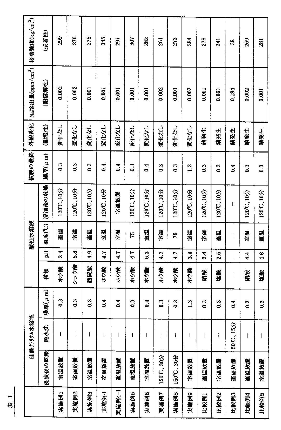
表1に示すように、特定の酸を含む酸性水溶液で浸漬処理した実施例1〜9の磁石サンプルでは、比較例1〜5の磁石サンプルと比較して、耐湿性(耐食性)、耐溶解性および接着性のいずれも優れていることが確認できた。
【0086】
参考例1
室温に調製された亜硫酸水溶液(pH=2.2)を用いた以外は、実施例1と同様にして永久磁石サンプルを得た。
【0087】
参考例2
珪酸ナトリウムの重量比を3%に調製した珪酸ナトリウム水溶液(モル比n=(SiO2 /Na2 O)=1)を用いた以外は、実施例1と同様にして永久磁石サンプルを得た。
参考例3
珪酸ナトリウムの重量比を80%に調製した珪酸ナトリウム水溶液(モル比n=(SiO2 /Na2 O)=2)を用いた以外は、実施例1と同様にして永久磁石サンプルを得た。
参考例4
85℃に調製されたホウ酸水溶液(pH=3.4)を用いた以外は、実施例1と同様にして永久磁石サンプルを得た。
【0088】
参考例1〜4で得られた永久磁石サンプルを用いて、耐湿性、耐溶解性および接着性の評価を行った。
その結果、参考例1のサンプルでは、酸処理に用いた水溶液のpHが2.2であったので、実施例1のサンプル(pH=3.4)と比較して磁石本体の素材が若干侵される傾向が見られたが、実用に際しては問題がないことが確認できた。
参考例2のサンプルでは、形成される被膜の厚みが0.005μmと薄膜であったため、実施例1のサンプル(膜厚=0.3μm)と比較して耐食性が低下する傾向が見られた。
参考例3のサンプルでは、形成される被膜の厚みが7.1μmの厚膜であったため、実施例1のサンプル(膜厚=0.3μm)と比較して被膜が均一に形成されない傾向が見られたが、実用に際しては問題がないことが確認できた。
参考例4では、ホウ酸水溶液の温度が85℃に調製されていたため、実施例1(ホウ酸水溶液の温度:室温)と比較して、被膜に損傷を与える傾向がみられたが、実用に際しては問題がないことが確認できた。
【0089】
【発明の効果】
以上説明してきたように、本発明によれば、耐食性や接着性に優れ、磁石周辺を汚染するおそれが少ない保護被膜を有する磁石を安価に製造できる磁石の製造方法を提供することができる。[0001]
BACKGROUND OF THE INVENTION
The present invention relates to a method for manufacturing a magnet that can be used in a rotating device or the like.
[0002]
[Prior art]
R-TM-B magnets containing R (R is one or more rare earth elements including Y), TM (TM is a transition element mainly composed of Fe), and boron are known to have excellent magnetic properties. ing. However, this R-TM-B magnet has a major drawback that it is very easily corroded as compared with general steel materials. Therefore, in order to compensate for this drawback, various surface treatments such as plating, ion plating, and resin coating have been applied to the surface of the magnet.
[0003]
In recent years, along with downsizing and energy saving of electrical equipment, high-performance magnets are required, and at the same time, cost reduction is also required. In particular, applications that do not require the performance of the conventional surface treatment are increasing, and the cost reduction of the surface treatment is strongly demanded. Further, in realizing high efficiency of various motor devices, the loss of magnetic properties due to the protective coating formed by subjecting the magnet to surface treatment cannot be ignored.
[0004]
Conventionally, as a simple rust prevention treatment technique for R-TM-B magnets, a chemical conversion treatment or a technique of immersing in an alkali silicate is known.
[0005]
Chemical conversion treatment is roughly classified into chromic acid and phosphate, but chromic acid treatment tends to be eliminated due to recent environmental problems.
[0006]
Japanese Examined Patent Publication No. 4-22008 discloses a method of forming a chemical conversion film composed of phosphate on the magnet surface by subjecting the surface of the R-TM-B magnet to phosphate treatment. However, when the usual phosphate treatment is performed on the R-TM-B magnet, the R-rich phase is selectively eluted due to galvanic corrosion in the magnet structure, and the chemical conversion film is not sufficiently formed. It has the disadvantage that it cannot be obtained.
[0007]
In JP-A-9-7867 and JP-A-10-154611, a method for forming a glassy protective film on the surface of a magnet by treating an R-TM-B magnet with an alkali silicate aqueous solution and drying by heating. Is disclosed.
However, the magnets obtained by the methods described in these publications contain a large amount of alkali components in the glassy protective film. Since the alkali component contained in this film has a property of absorbing moisture, the corrosion resistance of the film is likely to be lowered. Moreover, the film containing an alkali component also has a property of re-dissolving when it comes into contact with moisture. When the film is eluted, the adhesive strength of the film is lowered, and when it is incorporated in various devices, it may cause a problem of contaminating the periphery of the magnet. Further, when heat drying is performed at a high temperature, cracks are likely to occur in the coating, which may cause a problem that the corrosion resistance is lowered.
[0008]
In view of this, Japanese Patent Application Laid-Open No. 2000-40609 discloses the following rust prevention method for magnets. First, similarly to the above-mentioned JP-A-9-7867 and JP-A-10-154611, the R-TM-B magnet is treated with an alkali silicate aqueous solution and dried by heating, so that the surface of the magnet is glassy. A protective coating is formed. Next, this glassy protective film is washed with water. As a result, the alkali component remaining in the coating is removed to prevent a decrease in corrosion resistance and contamination around the magnet.
[0009]
[Problems to be solved by the invention]
However, it is difficult to sufficiently remove the alkali component contained in the glassy protective film formed on the magnet surface only by washing with the method described in JP-A-2000-40609, and at the time of washing with water. It has the disadvantage that the coating is redissolved. For this reason, there existed a fault that it was easy to produce variation in the quality of the magnet obtained. In particular, drying at a high temperature has been a cause of occurrence of cracks in the coating film, resulting in a problem that quality is impaired.
[0010]
JP-A-4-6807 discloses a magnet rust prevention method described below. First, an R-TM-B magnet is immersed in an alkali silicate aqueous solution and dried by heating, thereby forming a thick glassy protective film having a thickness of about 50 μm on the magnet surface. Next, this thick glassy protective coating is treated with nitric acid and dried by heating. Next, the glass film after the nitric acid treatment is subjected to an electroless plating process to deposit a metal on the defective portion of the glass film. That is, in the method described in JP-A-4-6807, a thick glassy protective film is formed on the surface of the magnet, and then the defect portion of the glass film is filled with a metal so that the corrosion resistance and wear resistance of the magnet are reduced. It is going to improve. Certainly, since the glass film is formed of a thick film, it is considered that the wear resistance of the magnet is improved.
[0011]
However, the treatment with nitric acid has a disadvantage that the corrosion proceeds when there is a defect in the coating. In particular, when the film is a thin film, the quality of the obtained magnet is lowered.
[0012]
Further, when the glass film after the nitric acid treatment is subjected to the electroless plating treatment, the following disadvantages occur. First, the hydrogen gas generated by the reaction of sodium hypophosphite causes the magnet body to absorb hydrogen and become brittle. Secondly, palladium chloride is used as an activation treatment before the electroless plating treatment. At this time, the magnet body may be attacked by chlorine in the liquid. Thirdly, if the electrolytic solution accumulates in the defective portion of the glass coating, it is not easily removed by washing, and therefore corrosion starts from here.
[0013]
The objective of this invention is providing the manufacturing method of the magnet which can manufacture the magnet which has the protective film which is excellent in corrosion resistance and adhesiveness, and there is little possibility of contaminating a magnet periphery at low cost.
[0014]
[Means for Solving the Problems]
In order to achieve the above object, a method of manufacturing a magnet according to the present invention includes:
Forming an alkali silicate coating on the surface of the magnet body containing the rare earth element;
Treating the alkali silicate coating with an acidic aqueous solution containing at least one selected from boric acid, oxalic acid and sulfurous acid.
[0015]
The method for treating the alkali silicate coating with the acidic aqueous solution is not particularly limited, and the alkaline silicate coating may be immersed in the acidic aqueous solution, or the acidic aqueous solution may be applied to the alkaline silicate coating. However, in terms of workability, it is preferable to immerse the alkali silicate coating in the acidic aqueous solution.
[0016]
It is preferable that the acidic aqueous solution is prepared at 80 ° C. or lower.
The treatment time with the acidic aqueous solution is preferably within 30 minutes.
It is preferable that the pH of the acidic aqueous solution is adjusted to 3 or more.
[0017]
The thickness of the alkali silicate coating formed on the surface of the magnet body is not particularly limited, but is preferably 0.01 μm or more and 5 μm or less in terms of quality and magnetic properties.
[0018]
The method for forming the alkali silicate coating on the surface of the magnet body is not particularly limited, and may be formed by immersing the magnet body in an alkali silicate aqueous solution, or by applying an alkali silicate aqueous solution to the magnet body. May be formed.
[0019]
The alkaline silicate aqueous solution used to form an alkali silicate coating on the surface of the magnet body has M2O · nSiO2(However, M is Na or K) is SiO23-50% in terms of conversion, M2SiO for O (where M is Na or K)2Molar ratio (n = SiO2/ M2O) is preferably from 0.5 to 15.
[0020]
The material of the magnet body is not particularly limited as long as it includes a rare earth element, but R (R is one or more of rare earth elements including Y), TM (TM is a transition element mainly composed of Fe). And R-TM-B rare earth magnets containing boron.
[0021]
[Action]
In general, silicates other than salts with alkali metals are sparingly soluble in water, and only alkali silicates exhibit good solubility in water. In forming the film, it is excellent in handleability. On the other hand, since the alkali silicate protective coating formed using the aqueous alkali silicate solution contains an alkali component, there is a drawback in that it will dissolve when it comes into contact with water again.
[0022]
In the method for producing a magnet according to the present invention, an alkali silicate film formed on the surface of a magnet body containing a rare earth element is treated with an acidic aqueous solution containing a specific acid.
[0023]
The alkali component in the alkali silicate coating formed on the surface of the magnet body is completely neutralized and removed by a simple method such as washing with a specific acid and then washing with pure water. A stabilized silicate film is formed on at least the surface of the film. As a result, corrosion resistance is imparted to the obtained magnet. Moreover, since the film after the treatment is stabilized, the film does not re-dissolve even if it comes into contact with water thereafter. As a result, the adhesive strength of the coating does not decrease, high adhesiveness can be maintained, and the magnet periphery is not contaminated after being incorporated in a motor device or the like.
[0024]
In JP-A-4-6807, the corrosion resistance of the magnet is ensured with a thick film of about 50 μm, but in the present invention, the corrosion resistance and adhesion of the magnet are secured even with a thin film of about 0.01 to 5 μm. Can do. When the coating is very thin, a large volume ratio of the magnet body in a magnet of a predetermined size can be obtained, and more magnetic flux can be obtained than before.
[0025]
As described above, as described in JP-A-4-6807, when the glass film after the nitric acid treatment is subjected to electroless plating, an electrolytic solution is accumulated in a defective portion of the glass film, and this is the starting point. Corrosion starts, but as in the present invention, by treating with a specific acid, an insoluble salt is generated between the magnet body and the R-rich phase such as Nd, which is the starting point of corrosion of the magnet body. Is reliably prevented.
[0026]
Although the specific use of the magnet which concerns on this invention is not specifically limited, Various industrial rotary equipment, consumer rotary equipment, an optical pick-up apparatus, etc. are illustrated. Examples of industrial rotating equipment include various motors used in automobiles, motorcycles, etc .; drive systems for machine tools, and the like. Examples of consumer rotating devices include various motors used for VTRs, CDs, MDs, DVDs, cassette stereos, and the like; motors for OA devices (computers, printers, copying machines, etc.), and the like. An optical pickup device is for recording and reproducing information on an optical disk as a recording medium. In general, an optical pickup device moves an objective lens in a tracking direction or a focus direction of the optical disc, and a light source or a light receiving device on a mounting base. And an optical system block for projecting laser light onto the optical disc via the objective lens and detecting the reflected light. When the magnet of the present invention is used in an optical pickup device, the magnet is used in a magnetic circuit that is a constituent member of an objective lens driving device.
[0027]
DETAILED DESCRIPTION OF THE INVENTION
In the present embodiment, an R-TM-B sintered magnet is given as an example of the rare earth magnet, and an example of a method for manufacturing the magnet will be described.
[0028]
(1) First, a magnet body is prepared. In this embodiment, the magnet body is an R-TM-B rare earth magnet including R (R is one or more of rare earth elements including Y), TM (TM is a transition element mainly composed of Fe), and B. Composed.
[0029]
The contents of R, TM and B are preferably 5.5 atomic% ≦ R ≦ 30 atomic%, 42 atomic% ≦ TM ≦ 90 atomic%, 2 atomic% ≦ B ≦ 28 atomic%. TM is basically composed of Fe and inevitable impurities. In particular, when a permanent magnet body is produced by a sintering method, the following composition is preferable.
[0030]
The rare earth element R includes at least one of Nd, Pr, Ho, and Tb, or one or more of La, Sm, Ce, Gd, Er, Eu, Pm, Tm, Dy, Yb, and Y. Those are preferred. In addition, when using 2 or more types of elements as R, mixtures, such as a misch metal, can also be used as a raw material.
[0031]
The content of R is preferably 5.5 to 30 atomic%. If the R content is too low, the crystal structure of the magnet becomes a cubic structure having the same structure as that of α-iron, so that a high coercive force (Hcj) cannot be obtained. The residual magnetic flux density (Br) is decreased.
[0032]
The TM content is preferably 42 to 90 atomic%. If the TM content is too small, Br decreases, and if too large, Hcj decreases. Note that by replacing part of Fe with Co, the temperature characteristics can be improved without deteriorating the magnetic characteristics. In this case, if the Co substitution amount exceeds 50% of Fe, the magnetic properties deteriorate, so the Co substitution amount is preferably 50% or less.
[0033]
The content of B is preferably 2 to 28 atomic%. If the B content is too small, the crystal structure of the magnet becomes a rhombohedral structure, so that Hcj is insufficient. If it is too large, the B-rich nonmagnetic phase increases, so Br decreases.
[0034]
In addition to R, TM, and B, Ca, O, C, etc. may be contained as unavoidable impurities in an amount of 3 atomic% or less.
[0035]
Furthermore, by replacing a part of B with one or more of C, P, and S, productivity can be improved and cost can be reduced. In this case, the amount of substitution is preferably 4 atomic% or less. In addition, Cu, Al, Ti, V, Cr, Mn, Bi, Nb, Ta, Mo, W, Sb, Ge, Sn, Zr, Ni are used to improve coercivity, improve productivity, and reduce costs. , Si, Hf or the like may be added. In this case, the total amount added is preferably 10 atomic% or less.
[0036]
The magnet body has a main phase with a substantially tetragonal crystal structure. The particle size of the main phase is preferably about 1 to 100 μm. And it usually contains 1-50% nonmagnetic phase by volume ratio.
[0037]
In order to manufacture such a magnet body, it is preferable to use a powder metallurgy method. Manufacture of the magnet main body by the powder metallurgy method is performed as follows. First, an alloy having a desired composition is produced using various alloy manufacturing processes such as a casting method and a strip casting method. Next, the obtained alloy is coarsely pulverized to a particle size of about 10 to 100 μm using a coarse pulverizer such as a jaw crusher, a brown mill, or a stamp mill. Finely pulverize to a particle size of about 5-5 μm. The resulting powder is then preferably molded in a magnetic field. The magnetic field strength at the time of molding is preferably 600 kA / m or more. The molding pressure is preferably 0.5 to 5 ton / cm2Degree. Next, the obtained molded body is sintered at 1000 to 1200 ° C. for 0.5 to 10 hours and rapidly cooled. The atmosphere during sintering is preferably in an inert gas such as Ar gas or in a vacuum. Thereafter, heat treatment (aging treatment) is preferably performed at 500 to 900 ° C. for 1 to 5 hours, preferably in an inert gas atmosphere or in vacuum, and processed into an arbitrary shape. The magnet body manufactured in this way is particularly excellent in magnetic characteristics when, for example, R is Nd.
[0038]
(2) Next, in the present embodiment, pretreatment such as washing is performed on the obtained magnet body.
[0039]
Although this pretreatment is an optional treatment in the present invention, the corrosion resistance of the coating can be further improved by performing this pretreatment. However, the coating performance is not significantly impaired by not performing the pretreatment.
[0040]
When pre-processing is performed, it is preferable to apply the following processes.
[0041]
First, barrel polishing is performed to remove burrs on the surface of the magnet body. Next, a degreasing process is performed to remove dirt on the surface of the magnet body, and ultrasonic cleaning is performed in ion-exchanged water after the cleaning. The degreasing liquid used in the degreasing treatment is not particularly limited as long as it is used for ordinary steel. When an alkaline degreasing solution is used, the cleaning effect is large, and when a component containing a chelating agent is further used, the effect of slightly etching the magnet surface is more preferable. As a component of the degreasing liquid, caustic soda (NaOH) is generally used as a main component, and other additives are not specified.
[0042]
Further, when the surface of the magnet body after degreasing is further cleaned, chemical etching may be performed. Nitric acid is preferably used as the acid used in the chemical etching. When plating a general steel material, non-oxidizing acids such as hydrochloric acid and sulfuric acid are often used. However, when the magnet body contains a rare earth element as in the magnet body in the present embodiment, the hydrogen generated by the acid is occluded on the surface of the magnet body when the treatment is performed using these acids. The site becomes brittle and a large amount of powdery undissolved material is generated. Since this powdery undissolved material causes surface roughness, defects and poor adhesion after the surface treatment, it is preferable not to include the above-described non-oxidizing acid in the chemical etching treatment solution. Therefore, it is preferable to use nitric acid, which is an oxidizing acid with little generation of hydrogen, and further, aldonic acid or a salt thereof is contained at the same time, and irregularities at a level that cannot be visually confirmed are formed on the surface. This is even more preferable since the adhesive strength of the is improved. Such an improvement in adhesion is selectively realized by aldonic acid or a salt thereof, but not by other organic acids such as citric acid or tartaric acid.
[0043]
The amount of dissolution of the surface of the magnet main body by such pretreatment is preferably 5 μm or more, preferably 10 to 15 μm in average thickness from the surface. By completely removing the deteriorated layer and the oxide layer by processing the surface of the magnet body, it is possible to reduce the starting point of corrosion on the magnet surface and further improve the corrosion resistance.
[0044]
The concentration of nitric acid in the treatment liquid used for the pretreatment is preferably 1 N or less, particularly preferably 0.5 N or less. If the concentration of nitric acid is too high, the dissolution rate of the magnet body is extremely fast, and it becomes difficult to control the amount of dissolution. In particular, the large amount of processing such as barrel processing results in large variations, and the dimensional accuracy of the product cannot be maintained. If the nitric acid concentration is too low, the amount of dissolution becomes insufficient. For this reason, the nitric acid concentration is desirably 1 N or less, particularly 0.5 to 0.05 N or less. The amount of Fe dissolved at the end of the treatment is about 1 to 10 g / l.
[0045]
In order to completely remove a small amount of undissolved substances and residual acid components from the surface of the magnet body subjected to the pretreatment, it is preferable to perform cleaning using ultrasonic waves. This ultrasonic cleaning is preferably performed in pure water with very few chlorine ions that generate rust on the surface of the magnet body. Moreover, you may perform the same water washing before and behind the ultrasonic cleaning, and in each process of the said pre-processing as needed.
[0046]
(3) Next, the surface of the magnet body that has been pretreated is treated with an alkali silicate solution to form an alkali silicate coating on the surface of the magnet body.
[0047]
In the present embodiment, a method is adopted in which the magnet body is immersed in an alkali silicate aqueous solution and dried to form an alkali silicate film on the surface of the magnet body. However, the present invention is not limited to this. .
[0048]
As alkali silicate, water glass (Na2O and SiO2Is a main component of sodium silicate), potassium silicate, etc., but water glass is preferred because it is inexpensive and easily available. SiO in aqueous solution2And M2The molar ratio with O (where M is an alkali metal such as Na or K, preferably Na or K) (n = SiO2/ M2O) is preferably in the range of 0.5 to 15, and more preferably in the range of 0.5 to 8 in terms of solubility in water and film stability after drying. If the molar ratio is too large, the coating becomes brittle and cracks are likely to occur.
[0049]
The alkaline silicate aqueous solution is M in ion-exchanged water.2O · nSiO2(Where M is an alkali metal such as Na or K) is SiO2It is preferable to dissolve about 3 to 50% in terms of conversion. SiO2When an aqueous solution in which about 3 to 50% is dissolved in terms of conversion is used, the film can be made uniform and uniform after drying. In order to make the coating more uniform, ultrafine silica, colloidal silica or the like may be added.
[0050]
Drying may be performed to such an extent that moisture on the surface of the coating is removed and adhesion between the objects to be coated does not occur, or may be left at room temperature. However, in order to improve workability, drying may be performed at a temperature of about 40 to 150 ° C., preferably about 40 to 120 ° C. for about 5 to 60 minutes, preferably about 5 to 30 minutes. The method of drying is not limited, and may be a method of blowing air. In addition, you may perform the immersion to alkaline silicate aqueous solution and a drying process 2 times or more as needed.
[0051]
The thickness of the alkali silicate coating formed on the surface of the magnet body is not particularly limited, but is preferably 0.01 μm or more and 5 μm or less, more preferably 0.05 μm or more and 3 μm or less. When the thickness of the formed film is too thin, it is difficult to obtain sufficient corrosion resistance. On the other hand, if the film is too thick, it is difficult to obtain a uniform film thickness, and the loss of magnetic properties increases. That is, from the viewpoint of obtaining a uniform film thickness while minimizing the loss of magnetic properties as much as possible and maintaining sufficient corrosion resistance, the film is preferably formed in the above range.
[0052]
Next, the alkali silicate coating formed on the surface of the magnet body is treated with an acidic aqueous solution, washed with pure water, and then the alkali silicate coating is cured to produce a silicate protective coating. The reason for washing with pure water is to prevent the acid from being concentrated after drying and corroding the magnet. However, in the present invention, all of the alkali silicate coating may be cured to produce a protective coating, but only the surface portion of the alkali silicate coating may be cured to produce a protective coating.
[0053]
In the present embodiment, a method is adopted in which the magnet body on which the alkali silicate film is formed is immersed in an acidic aqueous solution, washed in pure water and dried to cure the alkali silicate film. It is not limited to.
[0054]
Alkali silicates have the property of gelling when brought into contact with water-soluble organic solvents such as ethanol and acetone, but have the property of being dissolved again with water. However, when contacted with an acidic aqueous solution, the alkali silicate is hydrolyzed to form gel-like silicic acid, so that the solubility in water is significantly reduced.
[0055]
In the present invention, the acid contained in the acidic aqueous solution contains at least one selected from boric acid, oxalic acid, and sulfurous acid, and is in water with respect to R such as Nd (R is one or more of rare earth elements including Y). Those that produce insoluble salts are used. Of these, boric acid and oxalic acid are preferable in that they have a pH buffering action and can easily manage the solution. By treating with an acidic aqueous solution containing such a specific acid, the alkali silicate is cured, and the alkali component contained in the film is surely removed, and as a result, the film can be stabilized. The present inventors have found out.
[0056]
The acidic aqueous solution is preferably adjusted to have a pH of 3 or more, more preferably 4.5 or more. This is because if the pH of the solution is too low, the magnet body may be attacked if there are minute defects in the coating. The upper limit of the pH is preferably 7.
[0057]
The acidic aqueous solution is preferably adjusted to a temperature of 80 ° C. or lower, more preferably 50 ° C. or lower. By performing the treatment with an acidic aqueous solution prepared at a predetermined temperature or lower, the alkali component can be sufficiently removed from the coating without damaging the coating, and the coating can be stabilized.
[0058]
The treatment time with the acidic aqueous solution is preferably within 30 minutes, more preferably within 10 minutes. Alkali silicate cures quickly when it comes into contact with an acidic aqueous solution, so if the treatment time in an acidic aqueous solution is too long, it is not preferable in terms of productivity, and it may hinder efficient film stabilization. Because it becomes.
[0059]
In this embodiment, after immersing an alkali silicate film in an acidic aqueous solution, the film surface is dried by washing in pure water. At this time, drying is usually performed at 40 to 150 ° C. to remove moisture on the surface, but for simplification of the process, it may be immersed in alcohol and air-dried.
[0060]
By passing through the above processes, the permanent magnet by which the stabilized protective film was formed in the surface of a magnet main body is manufactured.
[0061]
In the method for producing a permanent magnet according to the present embodiment, the alkali silicate coating formed on the surface of the magnet body is immersed in an acidic aqueous solution containing a specific acid, and the alkali silicate coating is cured and stabilized. A protective coating is formed. Although the silicic acid protective film thus formed is extremely thin, the alkali component is completely neutralized and removed and stabilized. As a result, corrosion resistance is imparted to the obtained permanent magnet. Moreover, since the film after the treatment is stabilized, the film does not re-dissolve even if it comes into contact with water thereafter. As a result, the adhesive strength of the coating does not decrease, high adhesiveness can be maintained, and the surroundings of the magnet are not contaminated after being incorporated in a motor device or the like.
[0062]
As mentioned above, although embodiment of this invention was described, this invention is not limited to such embodiment at all, Of course, in the range which does not deviate from the summary of this invention, it can implement in various aspects. .
[0063]
【Example】
Hereinafter, embodiments of the present invention will be specifically described with reference to examples and comparative examples. The present invention is not limited to these.
[0064]
Example 1
An ingot made of powder metallurgy and having a composition of 14.7Nd-77.6Fe-1.6Co-6.1B (numbers are in atomic ratio) is coarsely pulverized, and further averaged by jet mill pulverization with an inert gas. A fine powder having a diameter of about 3.5 μm was obtained. The obtained fine powder is filled in a mold, and a magnetic field of 1185 kA / m is applied to 1.0 ton / cm.2Molded with the pressure of Subsequently, a sintered body was obtained through sintering and heat treatment in vacuum. The obtained sintered body was cut into a size of 10 mm × 20 mm × thickness 3 mm, further subjected to barrel polishing and alkali degreasing treatment to obtain a permanent magnet body.
[0065]
Next, a JIS-3 sodium silicate (manufactured by Asahi Denka Co., Ltd.) was dissolved in pure water, and a weight ratio: 20% sodium silicate aqueous solution (molar ratio n = (SiO 22/ Na2In O) = 3), the obtained permanent magnet body was immersed, left to stand at room temperature (25 ° C.) for 30 minutes, and dried to form a sodium silicate coating on the surface of the permanent magnet body. The film thickness of the sodium silicate coating was 0.3 μm.
[0066]
Next, the permanent magnet main body on which the sodium silicate film is formed is immersed in a boric acid aqueous solution (pH = 3.4) prepared at room temperature (25 ° C.): after 1 minute, after washing in pure water, By drying at 120 ° C. for 10 minutes, the entire sodium silicate coating was cured to produce a silicate protective coating. Thereby, a permanent magnet sample was obtained. The thickness of the produced silicic acid protective film was 0.3 μm.
[0067]
Example 2
A permanent magnet sample was obtained in the same manner as in Example 1 except that an oxalic acid aqueous solution (pH = 5.8) prepared at room temperature (25 ° C.) was used.
[0068]
Example 3
A permanent magnet sample was obtained in the same manner as in Example 1 except that a sulfurous acid aqueous solution (pH = 4.9) prepared at room temperature (25 ° C.) was used.
[0069]
Example 4
A permanent magnet sample was obtained in the same manner as in Example 1 except that a boric acid aqueous solution (pH = 4.7) prepared at room temperature was used.
Example 4-1
Except that the permanent magnet body immersed in boric acid aqueous solution for 1 minute was washed in pure water and left at room temperature to cure all of the sodium silicate coating to produce a silicate protective coating. A permanent magnet sample was obtained in the same manner as in No. 4.
[0070]
Example 5
A permanent magnet sample was obtained in the same manner as in Example 1 except that a boric acid aqueous solution (pH = 4.7) prepared at 75 ° C. was used.
[0071]
Example 6
A permanent magnet sample was obtained in the same manner as in Example 1 except that an aqueous boric acid solution (pH = 6.3) prepared at room temperature was used.
[0072]
Example 7
After immersing the permanent magnet body in an aqueous sodium silicate solution, it is allowed to stand at 150 ° C. for 30 minutes and dried to form a sodium silicate coating, and an aqueous boric acid solution prepared at room temperature (25 ° C.) (pH = 4.7) A permanent magnet sample was obtained in the same manner as in Example 1 except that was used.
[0073]
Example 8
After immersing the permanent magnet body in an aqueous sodium silicate solution, it was allowed to stand at 150 ° C. for 30 minutes and dried to form a sodium silicate coating, and an aqueous boric acid solution (pH = 4.7) prepared at 75 ° C. was used. A permanent magnet sample was obtained in the same manner as in Example 1 except for the above.
Example 9
Sodium silicate aqueous solution prepared by adjusting the weight ratio of sodium silicate to 50% (molar ratio n = (SiO2/ Na2A permanent magnet sample was obtained in the same manner as in Example 1 except that O) = 2) was used.
[0074]
Comparative Example 1
A permanent magnet sample was obtained in the same manner as in Example 1 except that an aqueous nitric acid solution (pH = 2.4) prepared at room temperature (25 ° C.) was used.
[0075]
Comparative Example 2
A permanent magnet sample was obtained in the same manner as in Example 1 except that a hydrochloric acid aqueous solution (pH = 2.6) prepared at room temperature (25 ° C.) was used.
[0076]
Comparative Example 3
After forming a sodium silicate coating on the permanent magnet body, it was immersed in pure water prepared at 50 ° C. for 15 minutes without being immersed in an aqueous boric acid solution (pH = 3.4) and dried. Obtained a permanent magnet sample in the same manner as in Example 1.
[0077]
Comparative Example 4
A permanent magnet sample was obtained in the same manner as in Comparative Example 1 except that the pH of the aqueous nitric acid solution was changed to 4.4.
[0078]
Comparative Example 5
A permanent magnet sample was obtained in the same manner as in Comparative Example 2 except that the pH of the hydrochloric acid aqueous solution was changed to 4.8.
[0079]
Using each of the permanent magnet samples obtained in Examples 1 to 9 and Comparative Examples 1 to 5, moisture resistance (corrosion resistance), dissolution resistance (contamination resistance), and adhesion were evaluated.
[0080]
“Moisture resistance” was performed by observing a change in appearance after a permanent magnet sample was placed in an 85 ° C., 85% RH test tank for 168 hours. The case of “no change” was evaluated as having corrosion resistance, and the case of “rusting” was evaluated as having no corrosion resistance.
[0081]
“Solution resistance” is obtained by immersing a permanent magnet sample in 50 cc of ultrapure water and leaving it at 40 ° C. for 20 hours, and then elution of Na from the magnet sample (ppm / cm2) Was measured by inductively coupled high-frequency plasma spectroscopy (ICP spectroscopy, Inductively Coupled Plasma Spectrometry). And the amount of Na elution into ultrapure water is 0.1 ppm / cm2Less (preferably 0.05 ppm / cm2The following cases were evaluated as having resistance to dissolution.
[0082]
“Adhesiveness” was applied to a permanent magnet sample by applying an anaerobic acrylic adhesive (Loctite 392), pressure-bonded to an iron plate whose surface was washed, and then charged into a dryer heated to 150 ° C. for 30 minutes. It evaluated by performing a compression shear test. And the adhesive strength is 80kg / cm2The above cases were evaluated as having good adhesion. In the compressive shear test, the number of samples was 10 each, the sample shape was 10 mm × 5 mm × thickness 3 mm, and the average value was the adhesive strength. The compression shear test was performed at a rate of 5 mm / min at room temperature.
[0083]
The results are shown in Table 1.
[0084]
[Table 1]
As shown in Table 1, in the magnet samples of Examples 1 to 9 immersed in an acidic aqueous solution containing a specific acid, compared to the magnet samples of Comparative Examples 1 to 5, moisture resistance (corrosion resistance), dissolution resistance It was confirmed that both the adhesive strength and the adhesiveness were excellent.
[0086]
Reference example 1
A permanent magnet sample was obtained in the same manner as in Example 1 except that a sulfurous acid aqueous solution (pH = 2.2) prepared at room temperature was used.
[0087]
Reference example 2
Sodium silicate aqueous solution prepared by adjusting the weight ratio of sodium silicate to 3% (molar ratio n = (SiO2/ Na2A permanent magnet sample was obtained in the same manner as in Example 1 except that O) = 1) was used.
Reference example 3
Sodium silicate aqueous solution prepared by adjusting the weight ratio of sodium silicate to 80% (molar ratio n = (SiO2/ Na2A permanent magnet sample was obtained in the same manner as in Example 1 except that O) = 2) was used.
Reference example 4
A permanent magnet sample was obtained in the same manner as in Example 1 except that a boric acid aqueous solution (pH = 3.4) prepared at 85 ° C. was used.
[0088]
The permanent magnet samples obtained in Reference Examples 1 to 4 were used to evaluate moisture resistance, dissolution resistance and adhesion.
As a result, in the sample of Reference Example 1, since the pH of the aqueous solution used for the acid treatment was 2.2, the material of the magnet body was slightly affected as compared with the sample of Example 1 (pH = 3.4). However, there was no problem in practical use.
In the sample of Reference Example 2, the thickness of the formed film was 0.005 μm, which was a thin film, and thus the corrosion resistance tended to be lower than that of the sample of Example 1 (film thickness = 0.3 μm).
In the sample of Reference Example 3, since the thickness of the formed film was 7.1 μm, it was observed that the film was not formed uniformly compared to the sample of Example 1 (film thickness = 0.3 μm). However, it was confirmed that there was no problem in practical use.
In Reference Example 4, since the temperature of the boric acid aqueous solution was adjusted to 85 ° C., there was a tendency to damage the coating film compared to Example 1 (temperature of boric acid aqueous solution: room temperature). Confirmed that there was no problem.
[0089]
【The invention's effect】
As described above, according to the present invention, it is possible to provide a method for producing a magnet that can produce a magnet having a protective coating that is excellent in corrosion resistance and adhesiveness and less likely to contaminate the periphery of the magnet at low cost.
Claims (7)
前記アルカリ珪酸塩被膜を、ホウ酸、シュウ酸および亜硫酸から選ばれる少なくとも一つを含み、pHが3以上に調製されている酸性水溶液で処理する工程とを有する磁石の製造方法。Forming an alkali silicate coating on the surface of the magnet body containing the rare earth element;
The alkali silicate coating, boric acid, viewed contains at least one selected from oxalic acid and sulfite method for producing a magnet having a step of treating with an acidic aqueous solution which is adjusted to pH 3 or more.
Priority Applications (1)
| Application Number | Priority Date | Filing Date | Title |
|---|---|---|---|
| JP2001133665A JP3740552B2 (en) | 2001-04-27 | 2001-04-27 | Magnet manufacturing method |
Applications Claiming Priority (1)
| Application Number | Priority Date | Filing Date | Title |
|---|---|---|---|
| JP2001133665A JP3740552B2 (en) | 2001-04-27 | 2001-04-27 | Magnet manufacturing method |
Publications (2)
| Publication Number | Publication Date |
|---|---|
| JP2002329629A JP2002329629A (en) | 2002-11-15 |
| JP3740552B2 true JP3740552B2 (en) | 2006-02-01 |
Family
ID=18981481
Family Applications (1)
| Application Number | Title | Priority Date | Filing Date |
|---|---|---|---|
| JP2001133665A Expired - Fee Related JP3740552B2 (en) | 2001-04-27 | 2001-04-27 | Magnet manufacturing method |
Country Status (1)
| Country | Link |
|---|---|
| JP (1) | JP3740552B2 (en) |
Families Citing this family (6)
| Publication number | Priority date | Publication date | Assignee | Title |
|---|---|---|---|---|
| CN100357490C (en) * | 2005-10-19 | 2007-12-26 | 哈尔滨工业大学 | Rare-earth transfer film method for increasing corrosion-resistance of light metal and its composite material surface |
| WO2008004472A1 (en) | 2006-07-03 | 2008-01-10 | Konica Minolta Opto, Inc. | Method for manufacturing glass substrate for information recording medium and magnetic disc using such method |
| WO2008004468A1 (en) | 2006-07-03 | 2008-01-10 | Konica Minolta Opto, Inc. | Method of cleaning, and process for producing, glass substrate, and magnetic disk utilizing the same |
| JP4835407B2 (en) * | 2006-11-28 | 2011-12-14 | Tdk株式会社 | Rare earth magnet and manufacturing method thereof |
| US8383252B2 (en) | 2007-09-28 | 2013-02-26 | Tdk Corporation | Rare earth magnet and its production method |
| JP7109222B2 (en) * | 2018-03-27 | 2022-07-29 | Jx金属株式会社 | Coated metal powder, method for producing the same, and laminate-molded article using the metal powder |
-
2001
- 2001-04-27 JP JP2001133665A patent/JP3740552B2/en not_active Expired - Fee Related
Also Published As
| Publication number | Publication date |
|---|---|
| JP2002329629A (en) | 2002-11-15 |
Similar Documents
| Publication | Publication Date | Title |
|---|---|---|
| KR102028607B1 (en) | Rare Earth Sintered Magnet and Making Method | |
| JP4656323B2 (en) | Method for producing rare earth permanent magnet material | |
| JP3897724B2 (en) | Manufacturing method of micro, high performance sintered rare earth magnets for micro products | |
| WO2007119553A1 (en) | Process for producing rare-earth permanent magnet material | |
| WO2007119551A1 (en) | Method for producing rare earth permanent magnet material | |
| JP4508175B2 (en) | Fluoride coat film forming treatment liquid and fluoride coat film forming method | |
| JP5573848B2 (en) | Corrosion-resistant magnet and manufacturing method thereof | |
| JP3740552B2 (en) | Magnet manufacturing method | |
| JP3698308B2 (en) | Magnet and manufacturing method thereof | |
| JP2008218647A (en) | Rare earth magnet acid cleaning method and rare earth magnet acid cleaned by the method | |
| JP2001160508A (en) | R-Fe-B PERMANENT MAGNET AND ITS MANUFACTURING METHOD | |
| JP3248982B2 (en) | Permanent magnet and manufacturing method thereof | |
| CN101447332B (en) | Rare earth magnet and method for making the same | |
| JP4424030B2 (en) | Rare earth magnet, method for producing the same, and method for producing a multilayer body | |
| JP2000040609A (en) | High corrosion resistant permanent magnet and method of manufacturing the same | |
| JP2003017349A (en) | Method of manufacturing magnet | |
| JP4760811B2 (en) | Rare earth magnet and manufacturing method thereof | |
| JP3208057B2 (en) | Corrosion resistant permanent magnet | |
| JP3935092B2 (en) | R-TM-B permanent magnet | |
| JP4372105B2 (en) | High corrosion resistance permanent magnet and method of manufacturing the same | |
| JP4173893B2 (en) | Rare earth magnet and manufacturing method thereof | |
| JPH0613211A (en) | Permanent magnet having excellent corrosion resistance and manufacture thereof | |
| US12146225B2 (en) | Method for recycling rare earth sintered magnet | |
| JP2005210135A (en) | Bonded structure and method of manufacturing the same | |
| JP4600332B2 (en) | Magnet member and manufacturing method thereof |
Legal Events
| Date | Code | Title | Description |
|---|---|---|---|
| A621 | Written request for application examination |
Free format text: JAPANESE INTERMEDIATE CODE: A621 Effective date: 20040511 |
|
| A977 | Report on retrieval |
Free format text: JAPANESE INTERMEDIATE CODE: A971007 Effective date: 20050527 |
|
| A131 | Notification of reasons for refusal |
Free format text: JAPANESE INTERMEDIATE CODE: A131 Effective date: 20050726 |
|
| A521 | Request for written amendment filed |
Free format text: JAPANESE INTERMEDIATE CODE: A523 Effective date: 20050916 |
|
| TRDD | Decision of grant or rejection written | ||
| A01 | Written decision to grant a patent or to grant a registration (utility model) |
Free format text: JAPANESE INTERMEDIATE CODE: A01 Effective date: 20051018 |
|
| A61 | First payment of annual fees (during grant procedure) |
Free format text: JAPANESE INTERMEDIATE CODE: A61 Effective date: 20051020 |
|
| R150 | Certificate of patent or registration of utility model |
Ref document number: 3740552 Country of ref document: JP Free format text: JAPANESE INTERMEDIATE CODE: R150 Free format text: JAPANESE INTERMEDIATE CODE: R150 |
|
| FPAY | Renewal fee payment (event date is renewal date of database) |
Free format text: PAYMENT UNTIL: 20091118 Year of fee payment: 4 |
|
| FPAY | Renewal fee payment (event date is renewal date of database) |
Free format text: PAYMENT UNTIL: 20101118 Year of fee payment: 5 |
|
| FPAY | Renewal fee payment (event date is renewal date of database) |
Free format text: PAYMENT UNTIL: 20111118 Year of fee payment: 6 |
|
| FPAY | Renewal fee payment (event date is renewal date of database) |
Free format text: PAYMENT UNTIL: 20121118 Year of fee payment: 7 |
|
| FPAY | Renewal fee payment (event date is renewal date of database) |
Free format text: PAYMENT UNTIL: 20121118 Year of fee payment: 7 |
|
| FPAY | Renewal fee payment (event date is renewal date of database) |
Free format text: PAYMENT UNTIL: 20131118 Year of fee payment: 8 |
|
| LAPS | Cancellation because of no payment of annual fees |