JP3737017B2 - Pile driver leader triggering device - Google Patents
Pile driver leader triggering device Download PDFInfo
- Publication number
- JP3737017B2 JP3737017B2 JP2000189176A JP2000189176A JP3737017B2 JP 3737017 B2 JP3737017 B2 JP 3737017B2 JP 2000189176 A JP2000189176 A JP 2000189176A JP 2000189176 A JP2000189176 A JP 2000189176A JP 3737017 B2 JP3737017 B2 JP 3737017B2
- Authority
- JP
- Japan
- Prior art keywords
- leader
- rope
- suspension beam
- fixed
- sling rope
- Prior art date
- Legal status (The legal status is an assumption and is not a legal conclusion. Google has not performed a legal analysis and makes no representation as to the accuracy of the status listed.)
- Expired - Fee Related
Links
Images


Landscapes
- Earth Drilling (AREA)
Description
【0001】
【発明の属する技術分野】
本発明は、補助クレーンの補助を用いて杭打ち機のリーダを引き起こす杭打ち機のリーダ引き起こし装置に関するものである。
【0002】
【従来の技術】
図1は、一般的な直結3点支持式杭打機であるパイルドライバの側面斜視図である。パイルドライバ1は、走行装置2および上部旋回体3からなる本体に、リーダ4を備えて構成されている。杭を所定の角度で打ち込めるように杭方向を規制するリーダ4は、本体後方左右から延びるバックステー5,6によって上部を支持され、下部はブラケット7により本体に直結されている。リーダ4の前方には、杭の頭部を打撃するハンマの移動方向を案内するガイドパイプ17が設けられている。ハンマは、リーダ4先端部のリーダヘッド18よりワイヤロープによって吊られ、ガイドパイプ17に沿って移動される。
【0003】
パイルドライバ1を図2に示す寝ている姿勢から図1に示す作業姿勢にセットするには、リーダ起伏ワイヤロープ8を引っ張ってリーダ4を引き起こす作業が必要となる。なお、図2において図1と同一部分には同一符号を用いてその説明は省略する。しかし、リーダ4が長尺の場合、リーダ4の引き起こし作業をパイルドライバ1の本体の自力だけで行うには、リーダ4の重量が重過ぎるため、補助クレーンを用いてリーダ4の引き起こし作業を補助する必要がある。
【0004】
図2に示すように、リーダ4の先端寄りに設けられたバックステーホルダ9の近傍には吊り金具10が設けられている。リーダ4の引き起こし作業の補助は、この吊り金具10の部分を補助クレーン11を用いて玉掛ロープ12で吊ることによって行われる。
【0005】
図3に示すリーダ角αがリーダ自力引き起こし可能角度以上になるまで補助クレーン11によってリーダ4を引き起こしたら、その後は、リーダ起伏ワイヤロープ8を引っ張ってパイルドライバ1の自力でリーダ4を引き起こす。なお、図3において図2と同一部分には同一符号を用いてその説明は省略する。この際、補助クレーン11は不用となるので、玉掛ロープ12を吊り金具10から取り外す。リーダ角α=90°になる手前までリーダ4を引き起こしたら、ステー吊りクレーン13,14を用いてバックステー5,6を吊り、本体後方左右のアウトリガビーム15,16上にバックステー5,6をそれぞれ固定する。バックステー5,6を本体に固定したら、さらにリーダ4をリーダ角α=90°になるまで自力で引き起こす。
【0006】
【発明が解決しようとする課題】
しかしながら、上記従来のパイルドライバ1においては、補助クレーン11を撤去する際、リーダ4を吊り上げるために吊り金具10に取り付けた玉掛ロープ12は、作業者が吊り金具10の位置までリーダ4に登って手作業により取り外している。吊り金具10は、通常、地上から20メートル以上の高所にあるため、玉掛ロープ12の取り外し作業は大変危険な作業となっている。また、杭打ち作業終了後、リーダ4を倒す際にも、作業者が吊り金具10の位置までリーダ4を登り、玉掛ロープ12を取り付けなければならず、大変危険である。
【0007】
【課題を解決するための手段】
本発明はこのような課題を解決するためになされたもので、補助クレーンのフックに掛けられた玉掛ロープによって両端部が吊られて中央部に抱えたリーダを引き起こす吊りビームと、リーダの前方の外周長手方向に設けられたガイドパイプに沿って吊りビームを摺動させる,ガイドパイプに着脱自在に設けられた摺動案内具と、リーダの前方の回動支点近傍に設けられた固定ラグと、一端がこの固定ラグに着脱自在に取り付けられ,他端が吊りビームに取り付けられ,玉掛ロープによって吊りビームが吊られる際の吊りビームの摺動位置を規定する固定ロープまたは固定リンクとから、杭打ち機のリーダ引き起こし装置を構成した。
【0008】
本構成のリーダ引き起こし装置によるリーダの引き起こしは、固定ラグおよび吊りビーム間に固定ロープまたは固定リンクを架け渡し、補助クレーンのフックに掛けられた玉掛ロープで吊りビームの両端部を吊ることによって行われる。吊りビームの両端部が吊られると、吊りビームは、摺動案内具に案内されて、ガイドパイプに沿ってリーダ先端へ向かう向きに摺動する。この吊りビームの摺動は固定ロープまたは固定リンクが伸び切った位置で停止する。この状態でさらに吊りビームの両端部が吊り上げられると、リーダの荷重は吊りビームにあずけられ、リーダは、吊りビームの中央部に抱えられて徐々に引き起こされて行き、自力引き起こし可能なリーダ角度まで立たされる。
【0009】
リーダはその後自力で直立し、杭打ち機は作業姿勢にセットされる。作業姿勢にセットされると、リーダ引き起こし装置は不要になって杭打ち機から取り外される。この取り外しは、玉掛ロープに吊られた吊りビームを吊り下げることによって行われる。吊りビームが吊り下げられると、吊りビームは、自重により、摺動案内具に案内されてガイドパイプに沿って降下し、地上に近い高さまで降ろされる。この状態で、固定ロープまたは固定リンクの一端が固定ラグから取り外されると共に、摺動案内具がガイドパイプから取り外され、リーダ引き起こし装置が杭打ち機から取り外される。
【0010】
また、本構成のリーダ引き起こし装置によるリーダの倒しは、地上に近い高さで、摺動案内具および吊りビームがガイドパイプに取り付けられ、固定ロープまたは固定リンクの一端が固定ラグに取り付けられて行われる。固定ロープまたは固定リンク、摺動案内具および吊りビームが取り付けられると、同様に地上に近い高さで、吊りビームの両端部に玉掛ロープが掛けられる。その後、玉掛ロープが補助クレーンによって持ち上げられることにより、吊りビームは、吊り上げられ、固定ロープまたは固定リンクによって規定される摺動位置まで摺動案内具の案内でガイドパイプを摺動する。この状態でリーダが自力で前方に倒れてその荷重が吊りビームにあずけられ、リーダは吊りビームに抱えられながら地上まで倒される。
【0011】
また、本発明は、玉掛ロープによって吊られる吊りビームの両端部間の距離および固定ロープまたは固定リンクの長さが、吊りビームの両端部間を底辺とし、補助クレーンによるフック位置を頂点として玉掛ロープが形成する2等辺三角形が、リーダのリーダヘッドをかわす大きさに設定されていることを特徴とする。
【0012】
本構成のリーダ引き起こし装置によるリーダの引き起こしおよび倒しは、上記構成の場合と同様にして行うことが出来、また、次のように行うことも出来る。つまり、吊りビームの両端部が玉掛ロープによって吊られ、上述した引き起こし時のようにしてリーダが自力引き起こし可能なリーダ角度まで立たされる。その後、さらに、吊りビームの両端部が吊られてリーダが直立させられ、さらに、玉掛ロープがリーダの後方へ移動させられ、リーダが杭打ち機本体側に少し傾斜させられる。リーダは後方に少し傾いたこの状態でステーによって支持される。
【0013】
次に、玉掛ロープがゆるめられて固定ロープまたは固定リンクの一端が固定ラグから取り外され、その後、玉掛ロープが持ち上げられて吊りビームが固定ロープまたは固定リンクと共に吊り上げられる。この状態で玉掛ロープがリーダの前方に移動させられ、玉掛ロープはリーダヘッドをかわす。この際、リーダヘッドは、吊りビームの両端部間を底辺とし、補助クレーンによるフック位置を頂点として玉掛ロープが形成する2等辺三角形内を通過する。リーダヘッドをかわした玉掛ロープはそのまま下ろされ、玉掛ロープに吊られた吊りビームおよび固定ロープまたは固定リンクが、後方に少し傾斜したガイドパイプに沿って共に降下し、地上に近い高さまで降ろされる。この状態で、摺動案内具がガイドパイプから取り外され、リーダ引き起こし装置が杭打ち機から取り外される。その後、リーダは後方に傾いた状態から自力で直立し、杭打ち機は作業姿勢にセットされる。作業姿勢からのリーダの倒しは、この引き起こしの逆の手順で行われる。
【0014】
このように本構成のリーダ引き起こし装置によれば、玉掛ロープが形成する2等辺三角形がリーダヘッドをかわす大きさに設定されているため、玉掛ロープは、リーダの後方から前方へ、ならびに前方から後方へ、リーダヘッドをかわして移動することが出来る。しかも、本構成のリーダ引き起こし装置では、玉掛ロープがリーダヘッドをかわす際、リーダが後方に少し傾斜させられ、固定ロープまたは固定リンクの一端が固定ラグから取り外されて吊りビームが持ち上げられるため、リーダヘッドは、玉掛ロープが形成する2等辺三角形の底辺に近い幅の広い部分を通過する。
【0015】
また、本発明は、吊りビームが、摺動案内具によってガイドパイプに沿って摺動させられるホルダと、玉掛ロープによって両端部が吊られる,ホルダに挿通されたシャフトとから構成されることを特徴とする。
【0016】
本構成によれば、玉掛ロープによって両端部が吊られるシャフトは、玉掛ロープから受ける荷重方向に応じてホルダ内を回動する。
【0017】
【発明の実施の形態】
次に、本発明による杭打ち機のリーダ引き起こし装置をパイルドライバに適用した一実施形態について説明する。
【0018】
図4は本実施形態による杭打ち機のリーダ引き起こし装置が適用される3点直結式パイルドライバ21の側面図である。なお、同図において図1と同一または相当する部分には同一符号を付してその説明は省略する。
【0019】
パイルドライバ21を同図のようにリーダ4が直立した作業状態にセットするリーダ4の引き起こし作業は、前述したように、リーダ起伏ワイヤロープ8を引っ張って行うが、リーダ4が長尺で重い場合には、リーダ引き起こし装置および補助クレーンを用いて引き起こし作業を補助する。
【0020】
図5は、本実施形態による杭打ち機のリーダ引き起こし装置の全体構成を示している。なお、同図において図4と同一部分には同一符号を付して説明する。円筒状のリーダ4の前方の外周長手方向に設けられたガイドパイプ17には、吊りビーム22がこのガイドパイプ17に沿って摺動可能に取り付けられている。リーダ4の前方の回動支点近傍には、固定ラグ23が溶接によって固定されている。なお、固定ラグ23のリーダ4に対する固定は、ボルトやピンを使用してリーダ4に固定する構造であっても構わない。この固定ラグ23には、固定ロープ24の一端が固定ピン25aによって着脱自在に取り付けられている。固定ロープ24は、2本のロープ24a,24bが固定ピン25cによって連結されて構成されており、その他端は、吊りビーム22に固定ピン25bによって取り付けられている。この固定ロープ24は、後述するように、玉掛ロープ12によって吊りビーム22が吊られる際、ガイドパイプ17に沿って摺動する吊りビーム22の摺動位置を規定する。
【0021】
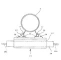
図6は、ガイドパイプ17に取り付けられている吊りビーム22をリーダヘッド18の方向から視た図である。なお、同図において図5と同一部分には同一符号を用いてその説明は省略する。同図に示すように、吊りビーム22は、摺動案内具である鈎手状のガイドギブ26によってガイドパイプ17に摺動自在に取り付けられている。ガイドパイプ17に引っ掛けられている左右で一対のガイドギブ26は、吊りビーム22の基体となるホルダ27にボルト28によって着脱自在に固定されている。ホルダ27には、筒状の穴があいており、この穴にシャフト29が回転自在に挿通されている。このシャフト29の両端には、吊り穴29a,29bが形成されている。吊り穴29a,29bには、玉掛ロープ12が掛けられるシャックル31が図7に示すように取り付けられる。
【0022】
図7は吊りビーム22がシャックル31を介して補助クレーン11で吊られる状態を示している。なお、同図において図5と同一部分には同一符号を付してその説明は省略する。玉掛ロープ12によって吊られる吊りビーム22の両端部間の距離および固定ロープ24の長さは、同図に示すように、吊りビーム22の両端部間を底辺とし、補助クレーン11によるフック位置を頂点として玉掛ロープ12が形成する2等辺3角形が、リーダ4のリーダヘッド18をかわす大きさに設定されている。
【0023】
このような構成のリーダ引き起こし装置によるリーダ4の引き起こしは次のように行われる。まず、水平に寝ているリーダ4のガイドパイプ17にガイドギブ26およびホルダ27を図6に示すように取り付け、ホルダ27にシャフト29を通す。次に、固定ラグ23および吊りビーム22間に固定ロープ24を取り付ける。その後、シャフト29の両端部にシャックル31を介して玉掛ロープ12を取り付け、この玉掛ロープ12を補助クレーン11のフックで吊り上げる。
【0024】
玉掛ロープ12が吊り上げられて吊りビーム22の両端部が吊られると、吊りビーム22はガイドギブ26に案内されて、ガイドパイプ17に沿ってリーダヘッド18へ向かう向きに摺動する。この吊りビーム22の摺動は固定ロープ24が伸び切った位置で停止する。吊りビーム22が停止した状態から、さらに吊りビーム22の両端部が吊り上げられると、リーダ4の荷重は吊りビーム22にあずけられ、リーダ4は、吊りビーム22の中央部に抱えられて、図8に示すように、徐々に引き起こされていく。
【0025】
リーダ4のリーダ角が自力で引き起こし可能な角度まで達したら、図4に示したリーダ起伏ワイヤロープ8を引っ張ってリーダ4を直立するまで自力で引き起こす。リーダ4が直立したら、前述したように、ステー吊りクレーンを用いてバックステー5,6を吊り、これらバックステー5,6をアウトリガビーム15,16上にそれぞれ固定する。このようにしてパイルドライバ21が作業姿勢にセットされると、リーダ引き起こし装置は不要となるので、パイルドライバ21から取り外す。
【0026】
リーダ引き起こし装置を取り外す際は、補助クレーン11を下降させて、玉掛ロープ12に吊られている吊りビーム22を下降させる。吊りビーム22は、玉掛ロープ12が吊り下げられると、自重により、ガイドギブ26に案内されてガイドパイプ17に沿って降下する。吊りビーム22が地上付近まで降下したら、固定ロープ24の一端を固定ラグ23から取り外す。これと共に図6に示したボルト28を取り外してガイドギブ26とホルダ27とを分離させ、ガイドギブ26をガイドパイプ17から取り外してリーダ引き起こし装置をパイルドライバ21から取り外す。
【0027】
杭打ち作業が終了してリーダ4を倒すときは、引き起こし作業の手順と反対の手順により行われる。まず、地上に近いリーダ4の下部において、ガイドギブ26をガイドパイプ17に取り付け、このガイドギブ26とホルダ27とをボルト28によって固定して吊りビーム22をリーダ4に取り付ける。次に、固定ロープ24の両端を吊りビーム22および固定ラグ23に取り付ける。さらに、吊りビーム22のシャフト29の両端にシャックル31を介して玉掛ロープ12を取り付ける。
【0028】
玉掛ロープ12を補助クレーン11のフックに掛けて吊り上げると、吊りビーム22は、固定ロープ24によって規定される摺動位置までガイドギブ26の案内でガイドパイプ17を摺動して上昇する。この状態で、リーダ起伏ワイヤロープ8が緩められ、バックステー5,6が伸ばされてリーダ4が自力で前方に倒れ、リーダ4の荷重が吊りビーム22にあずけられる。そして、リーダ4は、吊りビーム22に抱えられながら地上まで倒される。
【0029】
このように本実施形態による杭打ち機のリーダ引き起こし装置によれば、補助クレーン11で吊る玉掛ロープ12のリーダ4への取り付けおよび取り外し作業は、地上に近い低い高さで行える。従って、従来のようにこれらの作業を高所で行う必要がなくなる。この結果、作業を安全に行うことが出来る。
【0030】
また、本実施形態では、前述したように、玉掛ロープ12によって吊られる吊りビーム22の両端部間の距離および固定ロープ24の長さが、吊りビーム22の両端部間を底辺とし、補助クレーン11によるフック位置を頂点として玉掛ロープ12が形成する2等辺三角形が、リーダ4のリーダヘッド18をかわす大きさに設定されている。このため、本実施形態のリーダ引き起こし装置によるリーダ4の引き起こしは、次のように行うことも出来る。
【0031】
つまり、吊りビーム22の両端部を玉掛ロープ12によって吊り、上述した引き起こし時のようにしてリーダ4を自力引き起こし可能なリーダ角度まで立たせる。その後、さらに、吊りビーム22の両端部を吊ってリーダ4を直立させ、さらに、玉掛ロープ12をリーダ4の後方へ移動させて、図9に示すように、リーダ4をパイルドライバ21の本体側に少し傾斜させる。なお、同図において図8と同一部分には同一符号を付してその説明は省略する。リーダ4を後方に少し傾けたこの状態でステー5,6によって支持する。
【0032】
次に、玉掛ロープ12をゆるめて固定ロープ24の一端を図10に示すように固定ラグ23から取り外し、その後、玉掛ロープ12を持ち上げて吊りビーム22を固定ロープ24と共に吊り上げる。なお、同図において図9と同一部分には同一符号を付してその説明は省略する。この状態で玉掛ロープ12を、同図に示すように、リーダ4の前方に移動させてリーダヘッド18をかわさせる。この際、リーダヘッド18は、吊りビーム22の両端部間を底辺とし、補助クレーン11によるフック位置を頂点として玉掛ロープ12が形成する2等辺三角形内を通過する。
【0033】
次に、リーダヘッド18をかわした玉掛ロープ12をそのまま下ろし、玉掛ロープ12に吊られた吊りビーム22および固定ロープ24を、後方に少し傾斜したガイドパイプ17に沿って共に降下させて、地上に近い高さまで降ろす。この状態で、ガイドギブ26をガイドパイプ17から取り外し、リーダ引き起こし装置をパイルドライバ21から取り外す。その後、リーダ4を後方に傾いた状態から自力で直立させ、パイルドライバ21を作業姿勢にセットする。作業姿勢からのリーダ4の倒しは、この引き起こしの逆の手順で行う。
【0034】
このような構成のリーダ引き起こし装置によれば、玉掛ロープ12が形成する2等辺三角形がリーダヘッド18をかわす大きさに設定されているため、玉掛ロープ12は、リーダ4の後方から前方へ、ならびに前方から後方へ、リーダヘッド18をかわして移動することが出来る。しかも、本構成のリーダ引き起こし装置では、玉掛ロープ12がリーダヘッド18をかわす際、リーダ4が後方に少し傾斜させられ、固定ロープ24の一端が固定ラグ23から取り外されて吊りビーム22が持ち上げられるため、リーダヘッド18は、玉掛ロープ12が形成する2等辺三角形の底辺に近い幅の広い部分を通過する。従って、玉掛ロープ12は、より容易により大きなリーダヘッド18を交わすことが出来、パイルドライバ21に対するリーダ引き起こし装置の取り外しおよび取り付け作業はより容易に行える。
【0035】
また、本実施形態では、前述したように、吊りビーム22は、ガイドギブ26によってガイドパイプ17に沿って摺動させられるホルダ27と、玉掛ロープ12によって両端部が吊られる、ホルダ27に挿通されたシャフト29とから構成される。従って、玉掛ロープ12によって両端部が吊られるシャフト29は、玉掛ロープ12から受ける荷重方向に応じてホルダ27内を回動する。このため、吊りビーム22は、常に適正な荷重方向で玉掛ロープ12によって吊られ、リーダ4の引き起こしおよび倒し作業は円滑に行われる。
【0036】
なお、本実施形態においては、玉掛ロープ12によって吊りビーム22が吊られる際、ガイドパイプ17に沿って摺動する吊りビーム22の摺動位置を規定する固定ロープ24を用いた場合について説明したが、本発明はこれに限定されることはない。例えば、複数の節によって構成され、一端が固定ピン25aによって固定ラグ23に着脱自在に取り付けられ、他端が固定ピン25bによって吊りビーム22に取り付けられて吊りビーム22の摺動位置を規定する固定リンクを、固定ロープ24の代わりに用いた構成としてもよい。この場合においても、上記実施形態と同様な作用・効果が奏される。
【0037】
【発明の効果】
以上説明したように本発明によれば、補助クレーンの玉掛ロープの取り外しおよび取り付け作業は、地上に近い低い高さで行え、従来のように高所で行う必要が無くなる。従って、作業を安全に行うことが可能となる。
【0038】
また、玉掛ロープが形成する2等辺三角形がリーダヘッドをかわす大きさに設定されている場合には、玉掛ロープは、リーダの後方から前方へ、ならびに前方から後方へ、リーダヘッドをかわして移動することが出来る。しかも、リーダが後方に少し傾斜させられ、固定ロープの一端が固定ラグから取り外されて吊りビームが持ち上げられるため、リーダヘッドは、玉掛ロープが形成する2等辺三角形の底辺に近い幅の広い部分を通過する。このため、玉掛ロープはより容易により大きなリーダヘッドをかわすことが出来、杭打ち機に対するリーダ引き起こし装置の取り外しおよび取り付け作業はより容易に行える。
【0039】
また、吊りビームがホルダとこのホルダに挿通されたシャフトから構成される場合には、玉掛ロープによって両端部が吊られるシャフトは、玉掛ロープから受ける荷重方向に応じてホルダ内を回動する。このため、吊りビームは常に適正な荷重方向で玉掛ロープによって吊られ、リーダの引き起こしおよび倒し作業は円滑に行われる。
【図面の簡単な説明】
【図1】従来のパイルドライバの構成を示す側面斜視図である。
【図2】従来のパイルドライバのリーダが引き起こされる前の側面図である。
【図3】従来のパイルドライバのリーダ引き起こし時の側面図である。
【図4】本発明の一実施形態による杭打ち機のリーダ引き起こし装置が適用されるパイルドライバの側面図である。
【図5】本発明の一実施形態による杭打ち機のリーダ引き起こし装置の全体構成を示す正面図である。
【図6】図5に示す杭打ち機のリーダ引き起こし装置における吊りビームをリーダヘッド側からみた平面図である。
【図7】本発明の一実施形態によるリーダ引き起こし装置の吊りビームが玉掛ロープで吊られた状態を示す正面図である。
【図8】本発明の一実施形態によるリーダ引き起こし装置のリーダ引き起こし時の側面図である。
【図9】図8に示すリーダを後方に傾斜させたリーダ引き起こし装置の側面図である。
【図10】図9に示す玉掛ロープをリーダヘッドをかわしてリーダの前方に移動させた際のリーダ引き起こし装置の構成を示す側面図である。
【符号の説明】
21…パイルドライバ
4…リーダ
5,6…バックステー
11…補助クレーン
12…玉掛ロープ
17…ガイドパイプ
18…リーダヘッド
22…吊りビーム
23…固定ラグ
24…固定ロープ
25a,25b,25c…固定ピン
26…ガイドギブ
27…ホルダ
28…ボルト
29…シャフト
29a,29b…吊り穴
31…シャックル[0001]
BACKGROUND OF THE INVENTION
The present invention relates to a leader triggering device for a pile driver that causes the leader of the pile driver using the assistance of an auxiliary crane.
[0002]
[Prior art]
FIG. 1 is a side perspective view of a pile driver which is a general direct-coupled three-point support pile driver. The
[0003]
In order to set the
[0004]
As shown in FIG. 2, a
[0005]
When the
[0006]
[Problems to be solved by the invention]
However, in the
[0007]
[Means for Solving the Problems]
The present invention has been made in order to solve such a problem. A suspension beam that hangs both ends by a sling rope hung on a hook of an auxiliary crane and causes a leader held in the center, and a front of the leader A sliding guide provided detachably on the guide pipe for sliding the suspension beam along the guide pipe provided in the outer peripheral longitudinal direction, a fixed lug provided in the vicinity of the rotation fulcrum in front of the reader, One end is detachably attached to the fixed lug, the other end is attached to the suspension beam, and the pile is driven from a fixed rope or fixed link that defines the sliding position of the suspension beam when the suspension beam is suspended by the sling rope. Configured the machine to trigger the machine.
[0008]
Leading of the leader by the leader triggering device of this configuration is performed by suspending a fixed rope or a fixed link between the fixed lug and the suspended beam and suspending both ends of the suspended beam with a sling rope hung on the hook of the auxiliary crane. . When both ends of the suspension beam are suspended, the suspension beam is guided by the sliding guide and slides along the guide pipe in a direction toward the tip of the reader. The sliding of the suspension beam stops when the fixed rope or the fixed link is fully extended. If both ends of the suspension beam are further lifted in this state, the load of the leader is applied to the suspension beam, and the leader is gradually raised by being held in the center of the suspension beam until the leader angle that can be caused by itself. To stand.
[0009]
The leader then stands upright on his own and the pile driver is set in the working position. When set to the working position, the leader raising device is no longer needed and is removed from the pile driver. This removal is performed by suspending a suspension beam suspended from a sling rope. When the suspension beam is suspended, the suspension beam is guided by the sliding guide by its own weight, descends along the guide pipe, and is lowered to a height close to the ground. In this state, one end of the fixed rope or fixed link is removed from the fixed lug, the sliding guide is removed from the guide pipe, and the leader raising device is removed from the pile driving machine.
[0010]
In addition, the leader is tilted by the leader trigger device of this configuration at a height close to the ground, with the sliding guide and the suspension beam attached to the guide pipe, and one end of the fixed rope or fixed link attached to the fixed lug. Is called. When the fixed rope or fixed link, the sliding guide, and the hanging beam are attached, the slinging rope is hung on both ends of the hanging beam at a height close to the ground. Thereafter, when the sling rope is lifted by the auxiliary crane, the suspension beam is lifted and slides on the guide pipe by the guide of the sliding guide to the sliding position defined by the fixed rope or the fixed link. In this state, the leader falls forward by itself and the load is applied to the hanging beam, and the leader is brought down to the ground while being held by the hanging beam.
[0011]
In addition, the present invention provides a distance between both ends of the suspension beam suspended by the sling rope and the length of the fixed rope or the fixed link with the bottom between the both ends of the suspension beam and the hook position by the auxiliary crane as the apex. The isosceles triangle formed by is set to a size that does away with the reader head of the reader.
[0012]
The leader triggering device of this configuration can be used to trigger and knock down the reader in the same manner as in the above configuration, and can also be performed as follows. That is, both ends of the suspension beam are suspended by the sling rope, and the leader angle is set up to a leader angle at which the leader can be caused by itself as in the above-described raising time. Thereafter, both ends of the suspension beam are suspended to bring the leader upright, and the sling rope is moved to the rear of the leader, and the leader is slightly inclined toward the pile driving machine main body. The leader is supported by the stay in this state inclined slightly backward.
[0013]
Next, the sling rope is loosened and one end of the fixed rope or fixed link is removed from the fixed lug, and then the sling rope is lifted and the suspension beam is lifted together with the fixed rope or fixed link. In this state, the sling rope is moved in front of the leader, and the sling rope doesdges the leader head. At this time, the leader head passes through the isosceles triangle formed by the sling rope with the end between the both ends of the suspension beam as the base and the hook position by the auxiliary crane as the apex. The sling rope that has passed the leader head is lowered as it is, and the suspension beam and the fixed rope or fixed link suspended by the sling rope are lowered along the guide pipe slightly inclined rearward and lowered to a height close to the ground. In this state, the sliding guide is removed from the guide pipe, and the leader raising device is removed from the pile driving machine. After that, the leader stands upright by itself from a state inclined backward, and the pile driving machine is set to a working posture. The leader is brought down from the working posture in the reverse procedure of this cause.
[0014]
Thus, according to the leader raising device of this configuration, since the isosceles triangle formed by the sling rope is set to a size that dodges the leader head, the sling rope is from the back to the front and from the front to the back. Can move by moving the reader head. Moreover, in the leader raising device of this configuration, when the sling rope doesdges the leader head, the leader is slightly inclined backward, and one end of the fixed rope or fixed link is removed from the fixed lug, and the suspended beam is lifted. The head passes through a wide portion close to the base of the isosceles triangle formed by the sling rope.
[0015]
Further, the present invention is characterized in that the suspension beam is composed of a holder that is slid along the guide pipe by a sliding guide, and a shaft that is inserted into the holder and that is suspended at both ends by a sling rope. And
[0016]
According to this structure, the shaft in which both ends are suspended by the sling rope rotates in the holder according to the load direction received from the sling rope.
[0017]
DETAILED DESCRIPTION OF THE INVENTION
Next, an embodiment in which the leader raising device of the pile driving machine according to the present invention is applied to a pile driver will be described.
[0018]
FIG. 4 is a side view of the three-point directly connected
[0019]
When the
[0020]
FIG. 5 shows the entire configuration of the leader raising device of the pile driving machine according to the present embodiment. In the figure, the same parts as those in FIG. A
[0021]
FIG. 6 is a view of the
[0022]
FIG. 7 shows a state in which the
[0023]
The
[0024]
When the
[0025]
When the leader angle of the
[0026]
When removing the apparatus for raising the leader, the
[0027]
When the pile driving operation is completed and the
[0028]
When the
[0029]
Thus, according to the leader raising device of the pile driving machine according to the present embodiment, the attaching and detaching work of the
[0030]
Further, in the present embodiment, as described above, the distance between the both ends of the
[0031]
That is, both ends of the
[0032]
Next, the
[0033]
Next, the
[0034]
According to the leader raising device having such a configuration, the isosceles triangle formed by the
[0035]
In this embodiment, as described above, the
[0036]
In the present embodiment, the case where the fixed
[0037]
【The invention's effect】
As described above, according to the present invention, the operation of removing and attaching the sling rope of the auxiliary crane can be performed at a low height close to the ground, and there is no need to perform it at a high place as in the past. Therefore, the work can be performed safely.
[0038]
In addition, when the isosceles triangle formed by the sling rope is set to a size that dodges the leader head, the sling rope moves across the leader head from the back to the front and from the front to the back. I can do it. In addition, since the leader is slightly tilted backward, one end of the fixed rope is removed from the fixed lug and the hanging beam is lifted, so the leader head has a wide portion close to the base of the isosceles triangle formed by the sling rope. pass. For this reason, the sling rope can dodge a larger leader head more easily, and the work of removing and attaching the leader raising device to the pile driving machine can be performed more easily.
[0039]
Further, when the suspension beam is composed of a holder and a shaft inserted through the holder, the shaft whose both ends are suspended by the sling rope rotates in the holder according to the load direction received from the sling rope. For this reason, the suspension beam is always suspended by the sling rope in an appropriate load direction, and the work of raising and falling the leader is performed smoothly.
[Brief description of the drawings]
FIG. 1 is a side perspective view showing a configuration of a conventional pile driver.
FIG. 2 is a side view before a conventional pile driver leader is raised.
FIG. 3 is a side view of a conventional pile driver when a leader is raised.
FIG. 4 is a side view of a pile driver to which a leader raising device of a pile driving machine according to an embodiment of the present invention is applied.
FIG. 5 is a front view showing an entire configuration of a leader raising device of a pile driving machine according to an embodiment of the present invention.
6 is a plan view of a suspended beam in the leader raising device of the pile driving machine shown in FIG. 5 as viewed from the leader head side.
FIG. 7 is a front view showing a state in which the suspension beam of the leader raising device according to the embodiment of the present invention is suspended by a sling rope.
FIG. 8 is a side view of the leader trigger device when the reader is triggered according to an embodiment of the present invention.
FIG. 9 is a side view of the reader raising device in which the reader shown in FIG. 8 is inclined backward.
10 is a side view showing the configuration of the leader raising device when the sling rope shown in FIG. 9 is moved forward of the leader by passing the leader head. FIG.
[Explanation of symbols]
DESCRIPTION OF
Claims (3)
Priority Applications (1)
| Application Number | Priority Date | Filing Date | Title |
|---|---|---|---|
| JP2000189176A JP3737017B2 (en) | 2000-06-23 | 2000-06-23 | Pile driver leader triggering device |
Applications Claiming Priority (1)
| Application Number | Priority Date | Filing Date | Title |
|---|---|---|---|
| JP2000189176A JP3737017B2 (en) | 2000-06-23 | 2000-06-23 | Pile driver leader triggering device |
Publications (2)
| Publication Number | Publication Date |
|---|---|
| JP2002004754A JP2002004754A (en) | 2002-01-09 |
| JP3737017B2 true JP3737017B2 (en) | 2006-01-18 |
Family
ID=18688838
Family Applications (1)
| Application Number | Title | Priority Date | Filing Date |
|---|---|---|---|
| JP2000189176A Expired - Fee Related JP3737017B2 (en) | 2000-06-23 | 2000-06-23 | Pile driver leader triggering device |
Country Status (1)
| Country | Link |
|---|---|
| JP (1) | JP3737017B2 (en) |
-
2000
- 2000-06-23 JP JP2000189176A patent/JP3737017B2/en not_active Expired - Fee Related
Also Published As
| Publication number | Publication date |
|---|---|
| JP2002004754A (en) | 2002-01-09 |
Similar Documents
| Publication | Publication Date | Title |
|---|---|---|
| JP4857880B2 (en) | Mobile crane boom mounting method and boom mounting tool | |
| JP3737017B2 (en) | Pile driver leader triggering device | |
| JP3009375B2 (en) | Jib attachment / detachment device for crane beam | |
| CN109083146B (en) | Method for vertically setting upright post and inclined strut of pile driver | |
| JP2001220088A (en) | Winch attaching/detaching apparatus of mobile crane | |
| JP2003054876A (en) | Device and method for attaching and detaching side frame | |
| JP4186823B2 (en) | Tower crane | |
| JP3122068B2 (en) | Backstay positioning device for crane high mast | |
| JP6561574B2 (en) | Mobile crane and method for raising or lowering an attachment in a mobile crane | |
| EP3453670B1 (en) | Crane | |
| JP3696325B2 (en) | Pile driver leader undulation method and apparatus | |
| JP3174454B2 (en) | Method and device for installing and removing leader from pile driver | |
| JP3889521B2 (en) | Pile driver and its work floor mounting method | |
| JP4674938B2 (en) | Jib crane | |
| JP2005194088A (en) | Mobile crane | |
| JP2018127319A (en) | Mounting structure of jib mooring device | |
| JP7048376B2 (en) | Pile driver | |
| JP7286284B2 (en) | guide unit | |
| JPH0582982U (en) | Counterweight attachment / detachment equipment for construction work machines | |
| JP3446911B2 (en) | Front frame hoisting device | |
| JPH0328069Y2 (en) | ||
| JP3451862B2 (en) | Wheel crane jib containment device | |
| JP3612099B2 (en) | Retraction mechanism of upper device | |
| JP4836511B2 (en) | Self-propelled crane counterweight attachment / detachment device | |
| JPS5925961Y2 (en) | Pile driving leader with jib boom |
Legal Events
| Date | Code | Title | Description |
|---|---|---|---|
| A977 | Report on retrieval |
Free format text: JAPANESE INTERMEDIATE CODE: A971007 Effective date: 20051007 |
|
| TRDD | Decision of grant or rejection written | ||
| A01 | Written decision to grant a patent or to grant a registration (utility model) |
Free format text: JAPANESE INTERMEDIATE CODE: A01 Effective date: 20051025 |
|
| A61 | First payment of annual fees (during grant procedure) |
Free format text: JAPANESE INTERMEDIATE CODE: A61 Effective date: 20051025 |
|
| R150 | Certificate of patent or registration of utility model |
Free format text: JAPANESE INTERMEDIATE CODE: R150 |
|
| LAPS | Cancellation because of no payment of annual fees |