JP3733603B2 - Stretch wrapping machine - Google Patents
Stretch wrapping machine Download PDFInfo
- Publication number
- JP3733603B2 JP3733603B2 JP29644694A JP29644694A JP3733603B2 JP 3733603 B2 JP3733603 B2 JP 3733603B2 JP 29644694 A JP29644694 A JP 29644694A JP 29644694 A JP29644694 A JP 29644694A JP 3733603 B2 JP3733603 B2 JP 3733603B2
- Authority
- JP
- Japan
- Prior art keywords
- film
- folding
- plates
- plate
- folding plate
- Prior art date
- Legal status (The legal status is an assumption and is not a legal conclusion. Google has not performed a legal analysis and makes no representation as to the accuracy of the status listed.)
- Expired - Lifetime
Links
Images


Description
【0001】
【産業上の利用分野】
この発明は、ストレッチ包装機に関し、さらに詳しくは、水平に展張したフイルムに対して、被包装物を突き上げ、折込板により上記フィルムの左右及び後側を被包装物の底面に折込んだ後、被包装物を排出しながらフィルム前側の折込を行なうストレッチ包装機の改良に関する。
【0002】
【従来の技術】
尚、本願明細書で言う前側とは商品排出側である。
従来のストレッチ包装機の中には、被包装物を包装する包装部においてフイルムを水平に展張し、該フイルムに対して、被包装物を載置したエレベータを下から上昇させることにより、上記フィルムに対して被包装物を突き上げ、上記包装部の周囲に設けた左右折込板及び後折込板により、上記フィルムの左右及び後側を被包装物の底面に折込んだ後、被包装物を排出しながらフィルム前側の折込を行なうものがある。
【0003】
【発明が解決しようとする課題】
上記したストレッチ包装機は、フイルムの折込の際に、エレベータの上に載置される被包装物の底面に沿って、左右の折込板を水平に移動させることにより、フイルム左右の折込を行なうと共に、被包装物と上記左右折込み板との間に後折込み板を水平に入り込ませることにより、上記した如く左右に折り込んだフィルムをさらに後側から前側へ向けて折り込み、その後、被包装物を前方へ向けて排出することにより、フイルム前側の折込を行なうように構成してある。
上記ストレッチ包装機は、被包装物と上記左右折込み板との間に後折込み板を水平に入り込ませるように構成してあるため、後折込板による折込が完全に終了するまで、被包装物を下から支えるエレベータを降下させることが出来ず、この遅れから、包装の一行程を行なう処理速度が低下していた。
【0004】
上記したエレベータの降下タイミングを早くするために、後折込板は左右両折込板の下側を通過するように構成することが考えられるが、この場合、左右折込板により被包装物の底面に折り込まれたフィルムが後折込板により折込の際に前方に集められて左右に膨らんでしまい、その後、被包装物を排出する際に集められたフィルムが左右の折込板に引っ掛かってしまう問題を生じる。
本発明の目的は、上記した如きストレッチ包装機に対して、左右折込板による折込みの直後にエレベータを降下させることのできる機能を具備せしめ、これにより包装の処理速度を向上させることにある。
【0005】
【課題を解決するための手段】
上記した目的を達成するために本発明は、エレベータの上に載置した被包装物を、包装部において水平に展張したフィルムに対して突き上げ、そのフィルムの左右及び後側を折込板により被包装物の底面に折込んだ後、被包装物を排出しながらフィルム前側の折込みを行なうストレッチ包装機において、前記フィルムの左右の折込を行なう左右両折込板を具備し、該左右両折込板をそれぞれ上段の折込板と下段の折込板とにより構成すると共に、左右折込板における上下両段の折込板を一体的に連結し、その左右折込板によるフィルムの折込量を、上段の折込板にて浅く、且つ下段の折込板にて深くし、上記左右折込板における上下両段の折込板の間に後折込板を挿入し前後移動自在に支持し、且つ、上記左右両折込板の折込作動が開始されてから後折込板が折り込むまでの間に、エレベータを降下させる手段を設けてなるものである。
【0006】
上記ストレッチ包装機における前記左右両折込板は、上段の折込板の内側縁が下段折込板の内側縁よりも外側に位置している構成する。
【0007】
【作用】
以上の手段によれば、本発明のストレッチ包装機は、フィルムを包装部において水平に展張し、このフイルムに対して、エレベータ上に載置した被包装物を突き上げ、折込板によりフィルムの左右及び後側を被包装物の底面に折込み、上記被包装物を排出しながらフィルム前側の折込を行なう基本構成を有している。
上記したように、被包装物を突き上げた状態のフィルムを左右から折込む左右折込板は、上段の折込板と下段の折込板とにより構成される。また、上記上下両段の折込板の間には後折込板を挿入し前後移動自在に設けてある。
【0008】
上記した左右両折込板を構成する上下両段の折込板は、被包装物を突き上げた状態のフィルムに対して左右から折込作動し、フイルムの左右両側をエレベータ上に載置される被包装物の底面に折り込む。この時、上段の折込板がフィルムの折込と共にエレベータ上の被包装物の下に入り込んで下から支持する。
上下両段の左右両折込板が折込作動した後、上下両段の間に設けられる後折込板が作動し、上記したように左右折込板により被包装物の底面に折り込まれたフィルムをさらに前側へ向けて折り込む。
【0009】
左右折込板の折込作動が開始されてから後折込板が折り込むまでの間に、エレベータを降下させ、次ぎの包装行程に向けて作動させる。
後折込板によるフイルムの折込が終えた後、左右折込板により支えられる被包装物は、前方へ向けて排出されながら、前側のフィルム折込を行なってフイルムの折込を完了する。
また、被包装物底面の中央へ向けた左右折込板によるフィルムの折込量を、上段の左右折込板にて浅く、且つ下段の左右折込板にて深くしたものにおいては、上段の左右折込板による折込量が浅くなるので、被包装物を排出する際において、後折込板により前側に折り込まれたフィルム端部の引っ掛かりを低減させる。
さらに、上段の左右折込板における折込量を被包装物の前側で深く、後側にて浅くしたものにおいては、後折込板による折込の際の折込しろの幅を広く確保することができる。
【0010】
【実施例】
以下、本発明の一実施例を図面に基づいて説明する。
図1及び図2にて示すストレッチ包装機は、機枠Aの正面、即ち前部に被包装物を載置する載置部aを設け、該商品載置部aに載せた被包装物をコンベア1により機枠A内部に設けたエレベータ2まで搬送する。
上記エレベータ2上方には包装部bが設けられ、該包装部bの左右両側部に、フイルム保持部3a,3bと、該フイルム保持部3a,3bからフイルムeを水平に引き出すフィルムフィーダ6と、引き出したフイルムeの前後左右を切断して保持するクランプ7a,7b,8a,8bを設けてある。
また、フイルム保持部3の上には左右折込板4a,4bと後折込板5とを配設してある。
【0011】
上記したようにエレベータ2に載せられた被包装物は、エレベータの上昇により上記包装部bに展張されたフイルムeに対して突き上げられ、引き伸ばされた状態のフイルムeの端部を、上記左右折込板4a,4bと後折込板5とにより、被包装物の底面に折り込んだ後、排出プッシャー9により被包装物を機枠A前側の排出部cへ向けて水平に押動させながら、上記フィルムeの前側端部を折り込んでフィルムの折込を行なう。
【0012】
図4は被包装物を載置する載置部aを構成するコンベア1、及びエレベータ2を示している。コンベア1は、搬送方向へ向けて所定の間隔を置いて設けた駆動ローラ11aと分割ローラ11bとの間に、4本の無端ベルト11cを平行に架設することにより構成してある。各無端ベルト11cは幅方向に定間隔を置いて配置され、始端部における各無端ベルト11cの間には被包装物を載置する受け部材13を設け、これら受け部材13により載置された被包装物を下から支承するように構成してある。
また、上記各無端ベルト11cの外周には被包装物に当接する押し片12を横一線に並ぶ状態で付設し、上記各受け部材13の上に載置した被包装物の端部を上記押し片12にて受け止めながら搬送するように構成してある。
尚、上記コンベア1の一側には光センサ15が設けられ、上記コンベア1の上を移動する被包装物の縦、横、高さを検出し、後述する制御手段(図示せず)へ向けてその検出情報を出力する。また、制御手段は、上記検出情報に基づいてフィルムeの大きさを選択する。
【0013】
上記コンベア1の終端部に接続される形で設置されるエレベータ2は、5本の支持部材21を所定間隔を置いて垂直に立設して成り、これら各支持部材21の上面を面一状に一致させ、上記した各無端ベルト11cの間に挿入させて配置することにより、各コンベア1により搬送された被包装物を上記各支持部材21にて構成される受け面にて受取るように成っている。また、上記エレベータ2は、一体化した各支持部材21を昇降機構(図示せず)でもって支持することにより、降下位置であるコンベア1終端部と上昇位置である包装部bとの間を昇降するように構成してある。
【0014】
図2及び図5にて示すように、上記エレベータ2の直上で且つ包装部bの左右両側部に対応する位置には、フィルムeの保持部3a,3bを設けてある。
本実施例におけるストレッチ包装機はサイズの異る2本のフィルムロールe1,e2を機枠Aの左右に分けて一本ずつ配置してあり、これら両フィルムロールe1,e2から引き出したフィルムeを上記保持部3a,3bによって夫々保持している。
両保持部3a,3bは全く同様に構成され、機枠A内の左右両側部に対向する状態で設置してある。尚、上記保持部3a,3bは全く同様に構成してあるので、右側の保持部3aに基づいてその構造を説明する。
【0015】
図5にて示すように、保持部3aは、平面略櫛形に形成される2枚の保持板31を若干の間隙を介して重ね合わせた状態で機枠Aに対して水平に取付支持してある。フィルムロールe1から引き出されたフィルムeは、ロール32を迂回させて上記両支持板31の間に外側から挿入され、櫛形に切断される内側縁部までに引き出された状態で保持される。
また、上記左右両保持部3a,3bよりも幾分低いレベルには、2本のガイド軸35が保持部3a,3bの幅よりも幾分大きな間隔をおいて平行に取付支持してある。
上記したガイド軸35は、フィーダ6と左右のクランプ7a,7bの両端貫挿して摺動自在に支持することにより、上記フィーダ6と左右両クランプ7a,7bを、夫々フィルムeの引出し方向へ向けて水平に摺動移動するようにガイドするものである。
【0016】
フィーダ6は、タイミングベルト等を利用した駆動機構(図示せず)によって、上記ガイド軸35に沿って左右両方向に摺動移動し、右側若しくは左側のどちらか一方の保持部3a,3bにて保持されるフィルムeを選択的に掴持し、中央へ向けて引き出すものである。フィーダ6は、左右両ガイド軸35の間に跨ぐ連結部材61の下面に沿って支軸62を軸支し、該支軸62に沿って掴持板63を一体的に取り付け、揺動自在に支持している。即ち、フィルムeは、上記フィーダ6によりコンベア1終端部上を横切るように引き出されることになる。
掴持板63は、左右両側縁部を夫々櫛歯状に切欠形成し、これらの櫛歯部の各凸部が、前記したごとく櫛歯形に形成した保持部3a及び3bの対応する間隙に入り込むように構成してある。
【0017】
上記掴持板63は中央部の支軸62を支点として右側及び左側にシーソーのように回動し、連結部材61の右縁及び左縁と接触してフィルムeを掴持する。また、掴持板63の凸部の上面にはそれぞれ滑べり止め部材63aが付設され、上記した如き掴持板63の回動に伴って、上記滑べり止め部材63aと連結部材61下面との間でフイルムeを掴持するように成っている。
また、上記掴持板63の支軸62の一端部には回動アーム62aが取り付けられ、該回動アーム62aの先端に駆動シリンダ64を連結し、この駆動シリンダ64の伸縮作動により上記支軸62及び掴持板63が右側若しくは左側へ選択的に回動するように構成してある。
【0018】
上記右クランプ7aは、フィーダ6が右側の保持部3aにて保持されるフイルムeの先端部を掴持して水平に引出した後、引き出されたフィルムeの右端を掴持すると共に、その掴持位置にてフィルムeをカットするものであり、フィルムeの掴持機構と共にカッター74を具備している。
【0019】
右グランプ7aは、連結部材72の左右両端部に設けたブロック72aに両ガイド軸35を貫挿させることにより、上記ガイド軸35に沿って摺動移動自在に支持すると共に、タイミングベルト等を利用した駆動機構(図示せず)によって、上記フィーダ6と同様にガイド軸35に沿って左右両方向に摺動移動する。
上記した左右のブロック72aの間には、上記したフィーダ6の支軸62と同様な駆動機構により回動する支軸73を架設し、連結部材72の下面に沿って配置してある。上記支軸73には断面クランク形に折曲させた掴持板71の基端を取付け、該掴持板71の先端側縁をフィーダ6へ向けて状態で回動自在に支持する。上記掴持板71は基端の支軸73を支点として上下に回動し、上昇時に連結部材72の縁部と接触してフィルムフィーダ6により引き出されたフイルムeの後端部を掴持する。
また、上記掴持板71の中間部に沿ってはカッター74を設け、上記したように掴持板71がフィルムeの後端部を掴持するのと同時にフィルムeの掴持部の後側を上記カッター74で切断するように構成してある。
【0020】
また、上記した左クランプ7bは、フィルムフィーダ6により左側の保持部3bにて保持されるフイルムeが水平に引出された後、そのフィルムeの左端を掴持し、その掴持位置にてフィルムeをカットするものであり、上記右クランプ7aと全く同様に構成され、ガイド軸35上におけるフィルムフィーダ6の左側に設置される。
【0021】
図1、図2及び図4にて示すように、機枠A内に置ける上記左右クランプ7a,7bと同ベルの前後部には前クランプ8aと後クランプ8bとが設けてある。上記前後両クランプ8a,8bは、上記したようにフィルムフィーダ6と左右何れかのクランプ7a,7bとの間で保持したフィルムeの前端部及び後端部を掴持するものである。夫々のクランプ8a,8bは共に、ガイド軸35と平行に伸びる帯状の上板82と、該上板82に対して下から当接する昇降体81とにより構成され、これら81,82の両端部を図4にて示すようにコンベア1と平行に設置したガイド軸83,84に貫挿することにより前後方向へ摺動自在に支持してある。
【0022】
上記前後両クランプ8a,8bの昇降体81は、ガイド軸83の間にわたって架設される取付板81aの上に設置したシリンダロツド81bの作動により昇降作動し、上昇した際に上板82の下面に当接し、両者81,82の間でフィルムeを掴持する。また、前後両クランプ8a,8bの昇降体81と上板82とは、ガイド軸83,84の側方に沿って設けるタイミングベルト等の駆動機構により夫々同期した状態で前後に移動する。
よって、左右のフィルムロールe1若しくはe2から引き出されたフィルムeは、フィーダ6と左右何れかのクランプ7a,7bによって左右両端を掴持されると共に、上記した前後両クランプ8a,8bにより前端部と後端部を掴持され、四辺部を掴持された状態で包装部bの下で水平に展張された状態で保持される。
【0023】
包装部bにおける上記左右クランプ7a,7b及び前後両クランプ8a,8bの上部には、被包装物の突き上げにより引き伸ばされた状態のフィルムeの左右端部及び後端を、被包装物底面に折む左右折込板4a,4bと後折込板5とが設置してある。
図1乃至図3にて示すように、左右一対の折込板4a,4bを具備している。左右両折込板4a,4bは、夫々上段折込板42と下段折込板41とを小間隙を介して重ね合わせることにより構成してある。
図3にて示すように、左右折込板4a,4bの下段折込板41は、前後方向に伸びる帯状の板であり、その前後両端部に機枠aの左右側面間にわたって2本平行に取付支持したガイド軸43を貫挿することにより、両折込板41が相互間の平行を維持しながら左右両側から中央へ向けて水平に移動するように構成してある。
【0024】
左右両折込み板4a,4bの下段折込板41の上に設ける上段折込42は、下段折込板41と同様な帯状板からなり、その前後両端部を下へ向けて折曲させ、上記下段折込板41に対して止着することにより、下段折込板41の上に小間隙45を介して重ね合わせ一体化してある。
また、上記上段折込板42の内側縁には切欠44を切欠形成してある。
上記切欠44は、上段折込板42の前側から後側へ向けてテーパ状に切欠幅が大きくなるように形成してある。
上記切欠44の平面形状によれば、上段折込板42におけるフィルムeの折込量が前側で深く、後側で浅くなるようになる。
上記した切欠44は、フィルムe折込時に生じる引っ掛かりやフイルム接着面の確保を考慮したものであるが、その説明は後で述べる。
【0025】
上記左右折込板4a,4bの上下両段の折込板41,42間の小間隙45には左右幅方向方向に伸びる後折込板5を嵌装してある。
後折込み板5は、左右折込板4a,4bの外側に沿って取付支持したガイド軸46に左右両端部を嵌挿することにより水平に支持され、上下両段の折込板41,42間の小間隙45内に沿って前後に摺動移動する。
尚、上記した後折込板5と左右両折込板4a,4bの駆動は、夫々のガイド軸43,46に沿って設けた駆動ベルト等からなる駆動機構(図示せず)により行なう。
【0026】
また、上記後折込板5の上には排出プッシャー9を設けてある。排出プッシャー9は、後折込板5の上を後側から前側へむけて水平移動するように構成され、包装部bにてフィルムeの左右端部及び後端部の折込を終えた被包装物を機枠A前面側の排出部cへ向けて水平に押し出す。
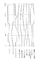
尚、上記した如く構成したストレッチ包装機において、コンベア1、エレベター2、フィルムフィーダ6、左右クランプ7a,7b、前後クランプ8a,8b、左右折込板4a,4b、後折込板5、排出プッシャー9の作動は、マイクロコンピュータ等により構成される制御部(図示せず)によって制御するものであり、例えば図20のタイムチャートにて示すように、上記各駆動部を所定のイミングにて作動せしめることにより、載置部a5載置した被包装物を所定の作動行程に沿って包装する。
【0027】
次に上記したストレッチ包装機の作動を図6乃至図20にて示す包装行程を追って説明する。
尚、本実施例にて示す被包装物fは、トレイに食品などを載せた状態のものである。
作業者は、包装機前面に突出する載置部aに被包装物fを載置する。載置部aを構成する受け部材13の上に載置された被包装物fは、作動するコンベア1の無端ベルト1に付設される押し片12により後から押されて水平に押し出され、無端ベルト11cの載ってエレベータ2の上まで搬送される(図6)。
上記したようにコンベア1上を被包装物fが搬送される際、コンベア1の一側部に設けたセンサ15により被包装物fの縦、横、高さのサイズが測定され、その検出信号を制御部(図示せず)へ向けて出力する。また、制御部はセンサによる被包装物fの寸法情報に基づいてフィルムeを引き出すフイルムe1,e2の選択、即ちフィルムサイズの選択を行なう。
【0028】
これと同時に、フィーダ6が選択されたフイルムe2の先端を掴持するため、保持部3bへ向けて移動する(図7)。尚、この説明では左側のフイルムe2を選択したが、反対に右側のフイルムe1を選択した場合は、図8にて示すようにフィーダ6が右側の保持部3aへ向けて移動することになる。
左端まで移動したフィーダ6は、保持部3bにて保持されるフィルムeの端部を掴持し、中央へ向けて引き出す(図10)。
フィーダ6によりフィルムeの端部が中央へ引き出された時、左クランプ7bがガイド軸35に沿って左側の保持部3bの前まで移動する(図11)。
保持部3bの前まで移動した左クランプ7bは水平に引き出されたフイルムeの左端をクランプする(図12)。左クランプ7bによるクランプと同時に、カッター74により上記フィルムeの左端が切断される。
【0029】
次いで、切断したフイルムeの左右両辺部を掴持するフィーダ6と左側クランプ7bとは更に右へ向けて移動し、掴持したフイルムeを包装部bの中央に合わせる(図13)。この時、フィーダ6と左クランプ7bとは、最初にフィルムeを掴持した時よりも広い間隔を置いて停止し、これにより掴持したフィルムeを左右方向に引っ張って適度な張力を与える。
さらに、前後両クランプ8a,8bが作動し、上記したフィルムeの前後両辺部をクランプする(図14)。これにより切断フィルムeは四辺をクランプされた状態となる。
そして、被包装物fを載せたエレベータ2が上昇し、包装部bにて展張されたフィルムeへ向けて突き上げられる(図15及び図16)。尚、エレベータ2に載って上昇した被包装物fは、トレイの底面が、左右折込板4a,4bの上段折込板42と略同じレベルに位置する状態となる。
【0030】
次いで、左右両折込板4a,4bが作動し、エレベータ2の上昇により被包装物fが突き上げられた状態のフイルムeに対して、左右両側から水平に折込作動して、フィルムeの左右両側端を被包装物fの底面に折込む。左右折込板4a,4bの上段折込板42は、フィルムeの折込と共にエレベータ2上の被包装物fの下に入り込み、エレベーダ2に代って被包装物fを下から支持する。
また、エレベーダ2は、上段折込板42による被包装物fの支持と同時に降下を開始し、次ぎに搬送されてくる被包装物fをコンベア1の終端部にて待つ(図17)。尚、エレベータ2を降下させるタイミングは、被包装物fが左右両折込板4a,4bにより支えられた瞬間から後折込板5が被包装物fの直下に位置する前までの間に設定し、その作動制御は前記したように制御部(図示せず)にて行なう。
【0031】
その直後、左右両折込板4a,4bの上下両段の折込板41,42の間に設けられる後折込板5が作動し、左右両側部を被包装物fの底面に折り込んだ状態のフィルムeを後から前へ向けて折り込み、その際、後クランプ8b、さらに左クランプ7bとフィルムフィーダ6が、夫々に掴持していたフィルムeの後端部、左右両端部を開放する(図18)。
図17にて示す折込作動時において、上段折込板42の内側縁が下段折込板41の内側縁よりも外側に位置するように構成してある。
その結果、包装部b中央へ向けた上段折込板42によるフィルムeの折込量は、上段折込板42にて浅く、下段折込板41にて深く折り込まれるようになり、これにより、後折込板5により前側に折り込まれた際に生じるフィルムe端部の集まりが被包装物fの排出時に上段折込板42への引っ掛かりを低減させることができる。
【0032】
また、前から後へ向けてテーパ状に広がる切欠44の平面形状によれば、上段折込板42におけるフィルムeの折込量が前側で深く、後側で浅くなるようになる。その結果、後折込板5によるフィルムe端部の折込の際の折込しろの幅を広く確保し、折しろ部分における接着面積を十分に確保すことができる。
上記したように後折込板5が左右折込板4a,4bの前端部まで移動した後、排出プッシャー9が作動し、左右折込板4a,4bの上にある被包装物fを前方の排出部cへ向けて水平に押し出し、さの最中に前クランプ8aが掴持していたフィルムeの前端部を開放する(図19)。これにより、被包装物fの底面にフィルムeの左右端及び前後端が180゜折り返されて被包装物fの底面に付着する。
【0033】
折込が終えて排出部cに置かれた被包装物fは、作業者が取り上げ、その底面部をヒートシール部dに押し当てて加熱、接着する。
尚、上記した実施例においては、左右両折込板4a,4bの上下両段の折込板41,42を一体的に連結固定したが、上記した上段折込板及び下段折込み板は、分離した状態で支持し、別々に作動させてもよい。
また、上記実施例の上段折込板4a,4bはテーパ状の切欠44を形成することにより、フイルムeを後側で浅く折り込むように構成したが、左右折込板の上段折込板は、板の前端部を枢支して水平面に沿って回動しながら折込作動するように支持し、これにより、上記実施例と同様にフイルムeの後側を浅く折込むように構成してもよい。
【0034】
【発明の効果】
本発明は以上説明したように、左右折込板を上下両段の左右折込板を重ね合わせ、これら上下両段の左右折込板の間を後折込板が移動するように構成したものであるから、左右折込板の折込作動と同時にエレベータ上の被包装物を上段の左右折込板により支え、従来のもののように後折込板による折込作動を待つことなく即座にエレベータの降下開始し、次ぎの包装行程へ向けて移動させる。その結果、包装速度の処理速度を向上させることができる。また、後折込板は被包装物に当ることがないのでスムーズに折り込める。
しかも、被包装物底面の中央へ向けた左右折込板によるフィルムの折込量を、上段の左右折込板にて浅く、且つ下段の左右折込板にて深くしたことにより、被包装物排出時において、後折込板により前側に折り込まれたフィルム端部の上段の左右折込板の引っ掛かりを有効に防止することができる。
更に、左右折込板を構成する上下段の両折込板を一体的に連結したことにより、上下両段の左右両折込板を重ね合わせて構成する左右折込板の構造を合理的に簡素化し、故障発生の低減とコストの低下を図ることができる。
【0035】
請求項2のように、左右両折込板を、上段の折込板の内側縁が下段折込板の内側縁よりも外側に位置している構成することで、前記した左右折込板によるフィルムの折込動作を確実に行うことができる。
【図面の簡単な説明】
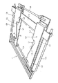
【図1】 本発明を実施したストレッチ包装機を示す縦断側面図。
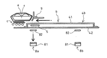
【図2】 図1におけるII-II 線断面図。
【図3】 包装部の左右折込み板及び後折込板を示す斜視図。
【図4】 コンベア及びエレベータ部を示す斜視図。
【図5】 フィルムフィーダ及び左右クランプを示す斜視図。
【図6】 被包装物を載置したコンベア部を示す側面図。
【図7】 左側の保持部を示す縦断正面図。
【図8】 右側の保持部を示す縦断正面図。
【図9】 フィルム端部をフィルムフィーダにより掴持した状態を示す左側保持部の縦断正面図。
【図10】 フイルム端部を引き出した状態を示す保持部の縦断正面図。
【図11】 フィルムフィーダによりフィルムを包装部に引き出した状態を示す縦断正面図。
【図12】 左クランプによりフィルムの左端を切断した状態を示す縦断正面図。
【図13】 フィルムフィーダと左クランプにより掴持したフィルムを包装部にてセンタリングした状態を示す縦断正面図。
【図14】 上記フィルムの後端部を後クランプにて掴持した状態を示す縦断正面ず。
【図15】 包装部に展張したフイルムに対して被包装物を突き上げた状態を示す縦断正面。
【図16】 同状態の縦断側面図。
【図17】 左右折込板を作動させた状態を示す縦断正面図。
【図18】 後折込み板を作動させた状態を示す縦断側面図。
【図19】 排出プッシャーにより被包装物を排出した状態を示す縦断側面図。
【図20】 各作動部の一行程を示すタイムチャート。
【符号の説明】
A・・・機枠
a・・・載置部
b・・・包装部
c・・・排出部
e・・・フィルム
1・・・コンベア
2・・・エレベータ
3a,3b・・・保持部
4a,4b・・・左右折込板
5・・・後折込板
6・・・フィルムフィーダ
7a,7b・・・左右クランプ
8a,8b・・・前後クランプ
9・・・排出クランプ
41・・・下段折込板
42・・・上段折込板[0001]
[Industrial application fields]
The present invention relates to a stretch wrapping machine, and more specifically, for a horizontally stretched film, after pushing up the package, and folding the left and right and rear sides of the film into the bottom of the package using a folding plate, The present invention relates to an improvement of a stretch wrapping machine that performs folding on the front side of a film while discharging an object to be packaged.
[0002]
[Prior art]
In addition, the front side said in this specification is a goods discharge side.
In a conventional stretch wrapping machine, the film is stretched horizontally in a wrapping part for wrapping a packaged article, and the elevator on which the packaged article is placed is raised from the bottom against the film. The left and right folding plates and the rear folding plate provided around the packaging part are folded into the bottom surface of the packaging material, and then the packaging material is discharged. However, there are some that fold in front of the film.
[0003]
[Problems to be solved by the invention]
The above stretch wrapping machine folds the film left and right by horizontally moving the left and right folding plates along the bottom surface of the article to be packaged placed on the elevator when the film is folded. The film folded in the right and left direction as described above is further folded from the rear side to the front side by horizontally inserting the rear folding plate between the packaging object and the left and right folding plates, and then the packaging object is moved forward. It is configured to fold the front side of the film by discharging toward the front.
Since the stretch wrapping machine is configured so that the rear folding plate is horizontally inserted between the packaged item and the left and right folding plates, the packaging material is removed until folding by the rear folding plate is completely completed. The elevator supported from the bottom could not be lowered, and the processing speed for carrying out one step of the packaging was reduced due to this delay.
[0004]
In order to accelerate the elevator descent timing described above, the rear folding plate may be configured to pass below the left and right folding plates. In this case, the left and right folding plates are folded into the bottom surface of the package. When the folded film is folded by the rear folding plate, the film is gathered forward and swells to the left and right, and then the collected film is caught by the left and right folding plates when the package is discharged.
An object of the present invention is to provide a stretch wrapping machine as described above with a function of allowing an elevator to be lowered immediately after folding by a left and right folding plate, thereby improving the packaging processing speed.
[0005]
[Means for Solving the Problems]
In order to achieve the above object, the present invention pushes up an object to be packaged placed on an elevator with respect to a film stretched horizontally in a packaging part, and the right and left sides and the rear side of the film are packaged by folding plates. In a stretch wrapping machine that folds on the bottom of an object and then folds the front side of the film while discharging the package, the left and right fold plates are respectively provided with left and right fold plates that fold the film left and right. Consists of an upper folding plate and a lower folding plateIn addition, the upper and lower folding plates in the left and right folding plates are integrally connected, and the amount of folding of the film by the left and right folding plates is made shallower in the upper folding plate and deeper in the lower folding plate,Between the upper and lower folding plates in the left and right folding plates, a rear folding plate is inserted and supported so as to move forward and backward, and after the folding operation of the left and right folding plates is started until the rear folding plate is folded, Means for lowering the elevator are provided.
[0006]
Above stretch wrapping machineThe left and right folding plates are configured such that the inner edge of the upper folding plate is positioned outside the inner edge of the lower folding plate.
[0007]
[Action]
According to the above means, the stretch wrapping machine of the present invention stretches the film horizontally in the wrapping section, pushes up the object to be packaged placed on the elevator against this film, and folds the left and right sides of the film and It has a basic configuration in which the rear side is folded into the bottom surface of the packaged object, and the film front side is folded while discharging the packaged object.
As described above, the left and right folding plates that fold the film in a state where the packaged object is pushed up from the left and right are constituted by the upper folding plate and the lower folding plate. A rear folding plate is inserted between the upper and lower folding plates so as to be movable back and forth.
[0008]
The upper and lower folding plates constituting the left and right folding plates are folded from the left and right with respect to the film in a state where the package is pushed up, and the left and right sides of the film are placed on the elevator. Fold it into the bottom. At this time, the upper folding plate enters under the package on the elevator together with the folding of the film and supports it from below.
After the left and right folding plates on both the upper and lower tiers are folded, the rear folding plate provided between the upper and lower tiers is actuated, and the film folded on the bottom surface of the package by the left and right folding plates as described above is further forward Fold it towards.
[0009]
The elevator is lowered from the start of the folding operation of the left and right folding plates until the rear folding plate is folded, and is operated for the next packaging process.
After the film has been folded by the rear folding plate, the package supported by the left and right folding plates is folded forward to complete the folding of the film while being ejected forward.
In addition, in the case where the amount of folding of the film by the left and right folding plates toward the center of the bottom of the package is shallow at the upper left and right folding plates and deepened by the lower left and right folding plates, the upper left and right folding plates Since the amount of folding becomes shallower, when the packaged article is discharged, the catch of the film end folded forward by the rear folding plate is reduced.
Furthermore, when the amount of folding in the upper left and right folding plates is deep on the front side of the package, and shallow on the rear side, the width of the folding margin when folding with the rear folding plate can be secured widely.
[0010]
【Example】
Hereinafter, an embodiment of the present invention will be described with reference to the drawings.
The stretch wrapping machine shown in FIG. 1 and FIG. 2 is provided with a placing part a for placing the article to be packaged on the front side of the machine frame A, that is, at the front, and It conveys to the
A packaging part b is provided above the
Further, left and
[0011]
As described above, the article to be packaged placed on the
[0012]
FIG. 4 shows a
Further, the outer periphery of each
An
[0013]
The
[0014]
As shown in FIGS. 2 and 5, holding
The stretch wrapping machine in this embodiment has two film rolls e1 and e2 of different sizes divided on the left and right sides of the machine frame A one by one, and the film e drawn from both film rolls e1 and e2 These are held by the holding
Both holding
[0015]
As shown in FIG. 5, the holding
Further, two
The above-described
[0016]
The
The
[0017]
The
A rotating arm 62a is attached to one end of the
[0018]
The
[0019]
The
A
A
[0020]
The
[0021]
As shown in FIGS. 1, 2 and 4, a
[0022]
The elevating
Therefore, the film e pulled out from the left and right film rolls e1 or e2 is gripped at both the left and right ends by the
[0023]
On the upper part of the left and
As shown in FIG. 1 thru | or FIG. 3, the left-right paired
As shown in FIG. 3, the
[0024]
The
A cutout 44 is formed in the inner edge of the
The notch 44 is formed in a tapered shape so that the notch width increases from the front side to the rear side of the
According to the planar shape of the notch 44, the folding amount of the film e in the
The above-mentioned notch 44 takes into consideration the catching that occurs when the film e is folded and the securing of the film adhesion surface, and the explanation thereof will be described later.
[0025]
A
The
The driving of the
[0026]
A
In the stretch wrapping machine configured as described above, the
[0027]
Next, the operation of the stretch wrapping machine will be described with reference to the wrapping process shown in FIGS.
The packaged item f shown in the present embodiment is a state where food or the like is placed on a tray.
An operator places the article to be packaged f on the placing portion a projecting from the front surface of the packaging machine. The article to be packaged f placed on the receiving
As described above, when the object f is conveyed on the
[0028]
At the same time, the
The
When the end of the film e is pulled out to the center by the
The
[0029]
Next, the
Further, both the front and
And the
[0030]
Next, the left and
Further, the
[0031]
Immediately thereafter, the
17 is configured such that the inner edge of the
As a result, the amount of folding of the film e by the
[0032]
Further, according to the planar shape of the notch 44 that tapers from the front to the rear, the folding amount of the film e in the
As described above, after the
[0033]
The article to be packaged f that has been folded and placed on the discharge portion c is picked up by the operator, and the bottom surface thereof is pressed against the heat seal portion d to be heated and bonded.
In the above-described embodiment, the upper and
In addition, the
[0034]
【The invention's effect】
As described above, since the left and right folding plates are overlapped with the upper and lower left and right folding plates and the rear folding plate moves between the upper and lower left and right folding plates as described above, the left and right folding plates Simultaneously with the folding operation of the plate, the package on the elevator is supported by the upper left and right folding plates, and the elevator starts to descend immediately without waiting for the folding operation with the rear folding plate like the conventional one, for the next packaging process To move. As a result, the processing speed of the packaging speed can be improved. In addition, since the rear folding plate does not hit the package, it can be smoothly folded.
In addition, the amount of folding of the film by the left and right folding plates toward the center of the bottom of the package is shallow at the upper left and right folding plates and deepened at the lower left and right folding plates, so that when the package is discharged, It is possible to effectively prevent the left and right folding plates on the upper end of the film end folded by the rear folding plate from being caught.
In addition, by integrally connecting the upper and lower folding plates that make up the left and right folding plates, the structure of the left and right folding plates that are constructed by overlapping the upper and lower folding plates is reasonably simplified, resulting in failure. Generation reduction and cost reduction can be achieved.
[0035]
As in claim 2By configuring the left and right folding plates so that the inner edge of the upper folding plate is located outside the inner edge of the lower folding plate, the film folding operation by the left and right folding plates can be reliably performed. .
[Brief description of the drawings]
FIG. 1 is a longitudinal side view showing a stretch wrapping machine embodying the present invention.
FIG. 2 is a sectional view taken along line II-II in FIG.
FIG. 3 is a perspective view showing left and right folding plates and a rear folding plate of a packaging unit.
FIG. 4 is a perspective view showing a conveyor and an elevator unit.
FIG. 5 is a perspective view showing a film feeder and left and right clamps.
FIG. 6 is a side view showing a conveyor unit on which an object to be packaged is placed.
FIG. 7 is a longitudinal front view showing a left holding part.
FIG. 8 is a longitudinal front view showing a right holding part.
FIG. 9 is a longitudinal front view of the left holding part showing a state in which the film end is gripped by the film feeder.
FIG. 10 is a longitudinal front view of the holding unit showing a state in which the end of the film is pulled out.
FIG. 11 is a longitudinal front view showing a state in which a film is pulled out to a packaging portion by a film feeder.
FIG. 12 is a longitudinal sectional front view showing a state in which the left end of the film is cut by the left clamp.
FIG. 13 is a longitudinal sectional front view showing a state where a film held by a film feeder and a left clamp is centered in a packaging unit.
FIG. 14 is a longitudinal front view showing a state where the rear end of the film is held by a rear clamp.
FIG. 15 is a longitudinal front view showing a state in which an object to be packaged is pushed up with respect to a film spread on a packaging portion.
FIG. 16 is a vertical side view of the same state.
FIG. 17 is a longitudinal front view showing a state in which the left and right folding plates are operated.
FIG. 18 is a longitudinal side view showing a state in which the rear folding plate is operated.
FIG. 19 is a vertical side view showing a state in which an object to be packaged is discharged by a discharge pusher.
FIG. 20 is a time chart showing one stroke of each operating unit.
[Explanation of symbols]
A ... Machine frame
a: Placement part
b ... Packing part
c ... discharge section
e ... Film
1 ... conveyor
2 ... Elevator
3a, 3b ... holding part
4a, 4b ... left and right folding plates
5 ... Rear folding plate
6 ... Film feeder
7a, 7b ... Left and right clamp
8a, 8b ... Front and rear clamps
9 ... discharge clamp
41 ... lower folding plate
42 ... upper folding plate
Claims (2)
Priority Applications (1)
| Application Number | Priority Date | Filing Date | Title |
|---|---|---|---|
| JP29644694A JP3733603B2 (en) | 1994-11-30 | 1994-11-30 | Stretch wrapping machine |
Applications Claiming Priority (1)
| Application Number | Priority Date | Filing Date | Title |
|---|---|---|---|
| JP29644694A JP3733603B2 (en) | 1994-11-30 | 1994-11-30 | Stretch wrapping machine |
Publications (2)
| Publication Number | Publication Date |
|---|---|
| JPH08151009A JPH08151009A (en) | 1996-06-11 |
| JP3733603B2 true JP3733603B2 (en) | 2006-01-11 |
Family
ID=17833654
Family Applications (1)
| Application Number | Title | Priority Date | Filing Date |
|---|---|---|---|
| JP29644694A Expired - Lifetime JP3733603B2 (en) | 1994-11-30 | 1994-11-30 | Stretch wrapping machine |
Country Status (1)
| Country | Link |
|---|---|
| JP (1) | JP3733603B2 (en) |
Families Citing this family (2)
| Publication number | Priority date | Publication date | Assignee | Title |
|---|---|---|---|---|
| KR101490339B1 (en) * | 2014-04-01 | 2015-02-06 | 주식회사 이랜텍 | Protective film sticking apparatus for connector |
| CN107199708B (en) * | 2017-07-19 | 2022-11-22 | 尚全平 | Full-automatic heat-sealing machine |
-
1994
- 1994-11-30 JP JP29644694A patent/JP3733603B2/en not_active Expired - Lifetime
Also Published As
| Publication number | Publication date |
|---|---|
| JPH08151009A (en) | 1996-06-11 |
Similar Documents
| Publication | Publication Date | Title |
|---|---|---|
| EP0692430B1 (en) | Unwrapping apparatus for stretch-wrapped load and shrink-wrapped load | |
| KR101041689B1 (en) | Vacuum packaging machine for product packages with multiple products | |
| US9272804B2 (en) | Bundle unwrapping machine | |
| JP4036024B2 (en) | Film packaging method and packaging apparatus therefor | |
| JP3733603B2 (en) | Stretch wrapping machine | |
| JPH0422766B2 (en) | ||
| JPH0260572B2 (en) | ||
| JPH08169408A (en) | Stretch film packaging machine | |
| JP3726298B2 (en) | Stretch film packaging machine | |
| JPS609124Y2 (en) | Film folding device of packaging machine | |
| JP2525392Y2 (en) | Cable band cutting / removal device | |
| JP2762961B2 (en) | Stretch film packaging machine | |
| JPH0418217A (en) | Ear-folding device of packing bag | |
| JP3569939B2 (en) | Stretch wrapping machine | |
| EP1580128A1 (en) | Apparatus for covering groups of products with tubular stretch film | |
| JPH0130326Y2 (en) | ||
| JP3301374B2 (en) | Stretch wrapping machine | |
| JPH0616212U (en) | Film packaging equipment | |
| JP4355393B2 (en) | Packaging equipment | |
| JPH0629051B2 (en) | Packaging equipment | |
| DK171636B1 (en) | Method for packaging of goods in film or foil material and apparatus for feeding and cutting of the film or foil material | |
| JPH0343124B2 (en) | ||
| JP2003024030A (en) | Machine for producing double-folded processed food | |
| KR860002259Y1 (en) | Corn paper wrapping machine | |
| JP2557590Y2 (en) | Film cutting machine for film packaging machine |
Legal Events
| Date | Code | Title | Description |
|---|---|---|---|
| A977 | Report on retrieval |
Free format text: JAPANESE INTERMEDIATE CODE: A971007 Effective date: 20050113 |
|
| A131 | Notification of reasons for refusal |
Free format text: JAPANESE INTERMEDIATE CODE: A131 Effective date: 20050329 |
|
| A521 | Written amendment |
Free format text: JAPANESE INTERMEDIATE CODE: A523 Effective date: 20050526 |
|
| TRDD | Decision of grant or rejection written | ||
| A01 | Written decision to grant a patent or to grant a registration (utility model) |
Free format text: JAPANESE INTERMEDIATE CODE: A01 Effective date: 20050927 |
|
| A61 | First payment of annual fees (during grant procedure) |
Free format text: JAPANESE INTERMEDIATE CODE: A61 Effective date: 20051010 |
|
| R150 | Certificate of patent or registration of utility model |
Free format text: JAPANESE INTERMEDIATE CODE: R150 |
|
| FPAY | Renewal fee payment (event date is renewal date of database) |
Free format text: PAYMENT UNTIL: 20091028 Year of fee payment: 4 |
|
| FPAY | Renewal fee payment (event date is renewal date of database) |
Free format text: PAYMENT UNTIL: 20091028 Year of fee payment: 4 |
|
| FPAY | Renewal fee payment (event date is renewal date of database) |
Free format text: PAYMENT UNTIL: 20091028 Year of fee payment: 4 |
|
| FPAY | Renewal fee payment (event date is renewal date of database) |
Free format text: PAYMENT UNTIL: 20101028 Year of fee payment: 5 |
|
| FPAY | Renewal fee payment (event date is renewal date of database) |
Free format text: PAYMENT UNTIL: 20101028 Year of fee payment: 5 |
|
| FPAY | Renewal fee payment (event date is renewal date of database) |
Free format text: PAYMENT UNTIL: 20111028 Year of fee payment: 6 |
|
| FPAY | Renewal fee payment (event date is renewal date of database) |
Free format text: PAYMENT UNTIL: 20111028 Year of fee payment: 6 |
|
| FPAY | Renewal fee payment (event date is renewal date of database) |
Free format text: PAYMENT UNTIL: 20121028 Year of fee payment: 7 |
|
| FPAY | Renewal fee payment (event date is renewal date of database) |
Free format text: PAYMENT UNTIL: 20121028 Year of fee payment: 7 |
|
| FPAY | Renewal fee payment (event date is renewal date of database) |
Free format text: PAYMENT UNTIL: 20121028 Year of fee payment: 7 |
|
| FPAY | Renewal fee payment (event date is renewal date of database) |
Free format text: PAYMENT UNTIL: 20131028 Year of fee payment: 8 |
|
| R250 | Receipt of annual fees |
Free format text: JAPANESE INTERMEDIATE CODE: R250 |
|
| R250 | Receipt of annual fees |
Free format text: JAPANESE INTERMEDIATE CODE: R250 |
|
| EXPY | Cancellation because of completion of term |