JP3733118B2 - PHOTOGRAPHING DEVICE AND PHOTO PROVIDING METHOD - Google Patents
PHOTOGRAPHING DEVICE AND PHOTO PROVIDING METHOD Download PDFInfo
- Publication number
- JP3733118B2 JP3733118B2 JP2003014426A JP2003014426A JP3733118B2 JP 3733118 B2 JP3733118 B2 JP 3733118B2 JP 2003014426 A JP2003014426 A JP 2003014426A JP 2003014426 A JP2003014426 A JP 2003014426A JP 3733118 B2 JP3733118 B2 JP 3733118B2
- Authority
- JP
- Japan
- Prior art keywords
- image
- input
- display
- display unit
- displayed
- Prior art date
- Legal status (The legal status is an assumption and is not a legal conclusion. Google has not performed a legal analysis and makes no representation as to the accuracy of the status listed.)
- Expired - Lifetime
Links
Images


Landscapes
- Cameras Adapted For Combination With Other Photographic Or Optical Apparatuses (AREA)
Description
【0001】
【発明の属する技術分野】
本発明は、ゲームセンター等に設置され、硬貨等の投入により使用者を撮影し、撮影画像をプリントして販売する写真撮影装置および写真提供方法に関するものである。
【0002】
【従来の技術】
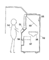
近年、ゲームセンター等において、写真を撮影してシールプリント等にする写真撮影装置が数多く設置されている。このような写真撮影装置としては、一般に、図15に示すようなものが用いられている。このものは、本体52の内部に、略45°の角度をもってハーフミラー53が設けられている。このハーフミラー53の奥に、使用者54を撮影するカメラ55が設けられ、ハーフミラー53の下方には、上記カメラ55で撮影された画像を表示するモニタ56が設けられている。図において51はコントローラ、57は写真プリント58を印刷するプリンタである。
【0003】
上記写真撮影装置では、ハーフミラー53を透してカメラ55で撮影された画像がモニタ56に表示され、このモニタ56に表示された画像がハーフミラー53に反射して使用者54によって確認できるようになっている。そして、使用者54は、モニタ56に映った自分の姿を確認しながら所望のポーズをとり、好みのところでコントローラ51を操作して静止画を撮影することが行われる。そして、この静止画は、適当なフレームや前景の画像と合成されて写真プリント58として印刷される。
【0004】
【発明が解決しようとする課題】
しかしながら、上記写真撮影装置では、カメラ55で撮影した写真をシール等の写真プリント58として、その場で出力できるにすぎない。最近では、写真撮影装置利用人口の増加とともに、そのニーズも多様化している。そこで、これらのニーズに応えるため、使用者54の画像に合成されるフレームや前景として各種の趣向を凝らしたものも数多く提供されているが、単にその場で写真プリント58として出力するだけの画一的なものでは満足されなくなってきている。
【0005】
そこで、最近では、カメラで撮影した画像をメモリに固定して液晶タブレット等に表示し、表示された固定画像にタッチペン等で手書き画像を入力して上記固定画像に合成する写真撮影装置も考案され実用化されている。
【0006】
上記写真撮影装置では、一旦撮影画像を静止画として固定してこの1枚の撮影画像に手書き画像を入力し合成してプリントするため、1回のプレイでは手書き画像が合成された撮影画像が1枚得られるにすぎない。ところが、1回のプレイで納得のいく撮影画像や手書き画像の入力を行なえればよいが、必ずしもそのような場合ばかりとは限らず、十分に納得できないままプレイが終了して画像がプリントアウトされてしまうこともしばしば起こりうる。このような場合、使用者としては、十分な満足を得ることができず、納得できるプリントを得るためには再び最初からプレイをやり直さなければならないため、時間も費用も同じだけかかり、無駄が多かった。一方、ゲームセンター等にとっては、同じ使用者に連続プレイをされると、それだけ顧客の回転率が悪くなって顧客に不満を与えかねない。
【0007】
一方、出願人による先行技術調査の結果、本願に関連する先行技術文献として、下記のものが開示されていた。先行技術1(下記の特許文献1)として、複数回撮像して得られた複数の被写体画像のうち必要とする被写体画像を選択してプリントすることで、無駄なく必要とする被写体画像のプリントを得ることができる証明写真作成装置が開示されている。先行技術2(下記の特許文献2)として、シールの形状および台紙上のその配置位置を自由に設定することができるシール自動販売装置が開示されている。
【0008】
【特許文献1】
特開2000−131753号
【特許文献2】
特開2000−11252号
【0009】
本発明は、このような事情に鑑みなされたもので、2つの画面で撮影画像に手書き画像等の第2画像を入力して合成画像を生成して出力することができる写真撮影装置および写真提供方法の提供を目的とする。
【0010】
【課題を解決するための手段】
上記の目的を達成するため、本発明の写真撮影装置は、被写体を撮影して複数の撮影画像を生成する撮影手段と、上記撮影画像を表示する表示手段と、使用者の操作により上記表示手段に表示された撮影画像に対し、上記撮影画像に合成される第2画像を入力する入力手段と、上記撮影画像と第2画像を合成して合成画像を生成する画像合成手段と、上記合成画像を所定のシートレイアウトで出力する画像出力手段とを備え、上記表示手段は、当該表示手段に向かって左側に設けられた左表示部と右側に設けられた右表示部の2つの表示部を備えて構成され、上記入力手段は上記左表示部と右表示部のそれぞれに対応するよう設けられた左入力部と右入力部の2つの入力部を備えて構成され、上記撮影手段で生成した複数の撮影画像を、上記左表示部と右表示部のそれぞれに振り分けて表示し、左表示部に表示された撮影画像に対しては左入力部で第2画像の入力が行われ、右表示部に表示された撮影画像に対しては右入力部で第2画像の入力が行われるように制御する制御手段を備えたことを要旨とする。
また、本発明の写真提供方法は、被写体を撮影して複数の撮影画像を生成する撮影手段と、上記撮影画像を表示する表示手段と、使用者の操作により上記表示手段に表示された撮影画像に対し、上記撮影画像に合成される第2画像を入力する入力手段と、上記撮影画像と第2画像を合成して合成画像を生成する画像合成手段と、上記合成画像を所定のシートレイアウトで出力する画像出力手段とを備えた装置による写真提供方法であって、上記表示手段は、当該表示手段に向かって左側に設けられた左表示部と右側に設けられた右表示部の2つの表示部を備えて構成され、上記入力手段は上記左表示部と右表示部のそれぞれに対応するよう設けられた左入力部と右入力部の2つの入力部を備えて構成され、上記撮影手段で生成した複数の撮影画像を、上記左表示部と右表示部のそれぞれに振り分けて表示する表示ステップと、左表示部に表示された撮影画像に対しては左入力部で第2画像の入力を行い、右表示部に表示された撮影画像に対しては右入力部で第2画像の入力を行う入力ステップとを実行することを要旨とする。
【0011】
すなわち、本発明は、上記表示手段は左表示部と右表示部の2つの表示部を備えて構成され、上記入力手段は上記左表示部と右表示部のそれぞれに対応した左入力部と右入力部の2つの入力部を備えて構成され、上記撮影手段で生成した複数の撮影画像を、上記左表示部と右表示部のそれぞれに振り分けて表示し、左表示部に表示された撮影画像に対しては左入力部で第2画像の入力が行われ、右表示部に表示された撮影画像に対しては右入力部で第2画像の入力が行われるように制御するため、左右の表示部と左右の入力部とのそれぞれで第2画像の入力ができ、複数人で利用する場合にそれぞれの利用者が楽しめ、満足できる。
【0012】
本発明において、上記複数の撮影画像を上記左表示部および右表示部のそれぞれに自動的に振り分けて表示するように制御することもできる。
【0013】
本発明において、上記制御手段は、上記複数の撮影画像を、利用者の選択入力により、上記左表示部および右表示部のそれぞれに振り分けて表示するように制御する場合、
上記制御手段は、上記左入力部で選択された撮影画像を左表示部に表示し、上記右入力部で選択された撮影画像を右表示部に表示するように制御する場合、
上記制御手段は、上記左表示部および右表示部にそれぞれ上記複数の撮影画像を選択可能に一覧表示して選択させるよう制御する場合には、
使用者が選択した好みの撮影画像を用いることができることから、より使用者が納得できる合成画像を得やすい。また、複数人で利用する場合にそれぞれの利用者が楽しめ、満足できる。
【0014】
本発明において、上記制御手段は、上記左表示部および右表示部のいずれかの表示部に表示するよう選択された撮影画像は、他方の表示部に表示するための選択をできないように制御する場合には、同じ撮影画像が2つのディスプレイの双方に表示されてしまうのが防止される。
【0015】
本発明において、上記ディスプレイに撮影画像を同時に2つ以上表示するとともに、上記第2画像入力手段により上記2つ以上の撮影画像に合成される第2画像を入力するようになっている場合には、1回のプレイで複数の撮影画像にそれぞれ第2画像を入力して合成画像を得るため、1回のプレイで使用者が納得できる合成画像を得やすく、使用者の満足度が高くなる。このため、プレイのやり直しの必要性が低下し、使用者にとっては時間と費用の節約となり、ゲームセンター等にとっては顧客の回転率の低下を防止できる。また、2つ以上の撮影画像を比べながら第2画像の入力ができることから、バラエティに富んだ合成画像が得られ、使用者の楽しみが大きくなる。
【0016】
本発明において、2つ以上の撮影画像を同じ大きさで並べて各ディスプレイに表示するようになっている場合には、2つ以上の撮影画像を見比べながら第2画像の入力ができる。
【0017】
本発明において、並べて表示された撮影画像の境界をまたぐように第2画像を入力しうるようになっている場合には、並べて表示された撮影画像の境界をまたぐように第2画像が合成された写真が得られる。
【0018】
本発明において、撮影手段により被写体を複数回撮影することにより2つ以上の撮影画像を生成してディスプレイに表示するようになっている場合には、1回のプレイで複数回の撮影による撮影画像を得てそれぞれ第2画像を入力して合成画像を得るため、使用者が納得できる撮影画像を得やすい。また、バラエティに富んだ合成画像が得られ、使用者の楽しみが大きくなる。
【0019】
本発明において、撮影手段により撮影された撮影画像を複写することにより2つ以上の撮影画像を生成してディスプレイに表示するようになっている場合には、同じ撮影画像を使って異なる第2画像を入力して合成した写真が得られる。
【0020】
本発明において、上記画像合成手段で合成された合成画像の中から出力する合成画像を選択する合成画像選択手段を備えている場合には、気に入った合成画像を選択して出力することから、1回のプレイで使用者が納得できる合成を得やすく、使用者の満足度が高くなる。また、あまり気に入らない画像に第2画像を入力する練習(たとえばペンやスタンプの試し書き)ができ、その後練習に用いた合成画像を出力しないような選択ができる。
【0021】
本発明において、2つ以上の撮影画像に第2画像を合成して出力する場合には、1回のプレイで使用者が納得できる合成を得やすく、使用者の満足度が高くなる。このため、プレイのやり直しの必要性が低下し、使用者にとっては時間と費用の節約となり、ゲームセンター等にとっては顧客の回転率の低下を防止できる。
【0022】
本発明において、上記合成画像選択手段で選択された合成画像の数に応じてシートレイアウトを決定するシートレイアウト決定手段を備えている場合には、使用者が気に入った合成画像の数に応じて最適なシートレイアウトが自動的に決定され、シートレイアウトの選択に失敗が起こらない。また、選択された合成画像数に応じて最適なシートレイアウトが決定されるため、1枚の写真プリント上で画像が印刷されない余白部分を少なくすることができ、複数の合成画像が印刷されている場合にも切り分けやすい配置にすることができる。
【0023】
本発明において、どの撮影画像をどのディスプレイに表示するかの選択は、表示したい方のディスプレイにおいて、表示された撮影画像の一覧から所望の撮影画像を選択することにより行われる場合には、複数人で利用する場合にそれぞれの利用者が楽しめ、満足できる。
【0024】
本発明において、上記シートレイアウト決定手段により複数のシートレイアウトが決定され、これら複数のシートレイアウトのなかから使用者の操作により使用者所望のシートレイアウトを選択しうるシートレイアウト選択手段を備えている場合には、最適のシートレイアウトの中から使用者の気に入ったシートレイアウトを選択できることから、使用者の満足度がより向上する。
【0025】
【発明の実施の形態】
つぎに、本発明の実施の形態を詳しく説明する。
【0026】
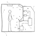
図1および図2は、本発明の写真撮影装置の一実施の形態を示す図である。この写真撮影装置は、内部および表面に各種の装置が設けられた筐体1と、上記筐体1の上下から被写体2の背後まで達するように突き出された支柱3とを備えている。そして、上記両支柱3の先端部分に、撮影の際の背景となるカーテン5が吊設され、上記筐体1,支柱3,カーテン5で囲まれた空間が、被写体2の撮影用ブースを形成している。上側の支柱3には、撮影用ブース内の被写体2を照射する2つのライト4が取り付けられている。
【0027】
上記筐体1の内部には、被写体2を撮影する2台のカメラ6a,6bが設けられている。上側のカメラ6aは被写体2をバストアップで撮影するものであり、下側のカメラ6bは被写体2の全身を撮影するものである。
【0028】
上記筐体1のカメラ6a,6bの被写体2側に位置する面には、透明板10が嵌め込まれている。また、上記筐体1の内部には、上記カメラ6a,6bから画像データを受信して画像合成等の処理を行なうコンピュータ装置7が設けられている。
【0029】
また、上記筐体1の被写体2側には、上記コンピュータ装置7から送信された合成画像等の画像信号を受信して画像を表示する2つのディスプレイ8a,8bが設けられている。さらに、上記筐体1の内部には、コンピュータ装置7から送信された画像データを受信し、この画像を印刷媒体15に印刷するプリンタ9が設けられている。このプリンタ9で印刷された印刷媒体15は、筐体1前面に形成された送出口19から送出されるようになっている。
【0030】
さらに、上記筐体1の被写体2側には操作パネルが設けられ、この操作パネルに、上記2つのディスプレイ8a,8bに対応した2つのコントローラ11a,11bが設けられている。上記コントローラ11a,11bは、それぞれタッチペン12a,12bを備えており、使用者2が各ディスプレイ8a,8bに表示される操作指示に従ってディスプレイ8a,8bの表面をタッチペン12a,12bでタップ(軽く叩く)等することにより、各種の操作信号がコンピュータ装置7に送られ、後述する各種の操作が行なわれるようになっている。
【0031】
また、上記各タッチペン12a,12bは、その先端をディスプレイ8a,8bの表面に接触させて文字や図形等を描いて入力しうるようになっており、手書き入力された文字・図形等の画像データやスタンプ画像等が、カメラ6a,6bで撮影された被写体2の撮影画像と合成されてディスプレイ8a,8bに表示され、その合成画像が印刷媒体15に印刷されるようになっている。
【0032】
また、筐体1の前面には、対価としてのコインを投入するコイン投入口18が設けられ、筐体1内部のコイン投入口18に隣接した位置に、投入されたコインを検出してコンピュータ装置7に検出信号を送信するコイン検出部17(図3参照)が設けられている。また、筐体1前面の適所には、コンピュータ装置7から音声信号を受信して出力するスピーカ(図示せず)が設けられている。
【0033】
この例において、使用者2がディスプレイ8a,8bから見る画像およびプリンタ9から印刷される画像は、被写体2の撮影像と、タッチペン12a,12bによる手書き入力画像等とが合成されたものである。
【0034】
つぎに、上記コンピュータ装置7のシステム構成について詳しく説明する。
【0035】
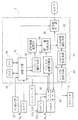
図3に示すように、コンピュータ装置7は、タッチペン12a,12bによりディスプレイ8a,8bの入力部35に入力された各種の操作信号をコントローラ11a,11bを介して受信し、受信した操作信号に応じて各種制御を行なう制御手段31を備えている。上記制御手段31は、コイン検出部17からの検出信号を受信することにより、撮影等の制御を開始するようになっている。
【0036】
なお、図3では、カメラ6a,6b、ディスプレイ8a,8b、コントローラ11a,11b、タッチペン12a,12bは、それぞれ1つだけ示している。
【0037】
上記ディスプレイ8a,8bには、タッチペン12a,12bによって手書き画像や操作信号が入力される入力部35と、画像等を表示する表示部36とが設けられている。上記タッチペン12a,12bで入力された手書き画像等は、ペン入力画像記憶部32に記憶され、記憶された手書き画像等のデータは、後述する画像合成手段30に送られる。また、タッチペン12a,12bによって入力された操作信号は、コントローラ11a,11bを介して制御手段31に送られ、各種の制御が行なわれる。
【0038】
上記コンピュータ装置7には、タッチペン12a,12bによるペン入力画像の入力可能時間を計測するタイマ26が設けられている。上記タイマ26は、制御手段31による手書き画像開始の指示メッセージをディスプレイ8a,8bに表示させるのとほぼ同時に計測を開始する。上記タイマ26の計測時間があらかじめ設定された所定の入力可能時間(例えば90秒等)に達したときに手書き画像等の入力を停止してつぎの動作に移るようになっている。
【0039】
そして、上記コンピュータ装置7には固定画像記憶部38が設けられ、上記被写体2によるタッチペン12a,12bの操作により所望のシャッタタイミングで撮像映像を静止画像として固定するようになっている。
【0040】
また、上記コンピュータ装置7には、シャッタ操作によるカメラ6a,6bでの撮影回数をカウントするカウンタ25が設けられている。上記カウンタ25は、コイン検出部17による最初のコインの検出によってリセットされてカウントを開始する。上記カウンタ25のカウントがあらかじめ設定された所定の撮影可能回数(例えば4回等)に達するまで、所定の時間間隔で撮影を繰り返し、2つ以上の複数の撮影画像(静止画像)を得るようになっている。
【0041】
そして、この写真撮影装置では、上記カメラ6a,6bによる静止画像の固定を複数回行い、複数の撮影画像を生成して固定画像記憶部38に記憶するようになっている。上記複数の撮影画像は、ディスプレイ8a,8bの表示部36にそれぞれ一覧表示されて使用者2に対してプレビュー確認させるようになっている。
【0042】
また、上記コンピュータ装置7には、ディスプレイ選択手段37が設けられ、上記一覧表示された2つ以上の撮影画像を2つのディスプレイ8a,8bのうちいずれのディスプレイ8a,8bに表示するかを使用者2がタッチペン12a,12bを操作して選択するようになっている。なお、このとき1つのディスプレイ8a,8bに表示させる画像はひとつでもよいし複数でもよい。そして、上記ディスプレイ選択手段37で選択された撮影画像は、それぞれのディスプレイ8a,8bの表示部36に並べて表示され、この状態で手書き画像の入力が行なわれる。
【0043】
さらに、上記コンピュータ装置7には画像合成手段30が設けられ、上記ディスプレイ選択手段37で選択されたディスプレイ8a,8bに表示された撮影画像に、タッチペン12a,12bによってディスプレイ8a,8bの入力部35に入力され、ペン入力画像記憶部32に記憶された文字や図形等の手書き画像等を合成するようになっている。上記画像合成手段30で合成された2つ以上の合成画像は、ディスプレイ8a,8bの表示部36に表示されるようになっている。
【0044】
また、上記コンピュータ装置7には、上記画像合成手段30で合成された撮影画像とペン入力画像との2つ以上の合成画像から、使用者2がタッチペン12a,12bの操作により、表情がよかったりペン入力画像の出来がよい等の理由により、印刷出力を希望する気に入った合成画像を選択する合成画像選択手段33を備えている。上記合成画像選択手段33で選択されて印刷出力に供される合成画像は、少なくとも1つ以上である。
【0045】
また、上記コンピュータ装置7には、上記合成画像選択手段33で選択された印刷出力される合成画像の数に応じて適切なシートレイアウトを複数自動的に決定するシートレイアウト決定手段34を備えている。
【0046】
上記シートレイアウト決定手段34は、印刷出力される合成画像の種類と数によってあらかじめ準備されたシートレイアウトの中から、使用者2が印刷出力するために選択した合成画像の種類と数に応じて適切なシートレイアウトを自動的に決定する。例えば、使用者2が選択した合成画像が、全身画像1枚とバストアップ画像2枚であれば、それに応じたシートレイアウトを例えば3つ決定する。
【0047】
また、上記コンピュータ装置7は、上記シートレイアウト決定手段34で自動的に決定された複数のシートレイアウトの中から、使用者2がタッチペン12a,12bの操作により印刷出力を希望するシートレイアウトを選択するシートレイアウト選択手段40を備えている。
【0048】
そして、プリンタ9による印刷を制御する印刷制御部(図示せず)により、上記シートレイアウト選択手段40で選択されたシートレイアウトによる写真プリントが印刷出力される。このとき、使用者2による指示により、手書き画像入力の際に並べて表示された撮影画像を1枚の写真として印刷したり、別々の写真として印刷することが行なわれる。
【0049】
また、上記コンピュータ装置7には、送受信手段39が設けられている。上記送受信手段39は、例えばインターネット等の通信回線(NET)に接続され、撮影画像や合成画像を上記通信回線を介して外部に出力し、外部のサーバに格納したり端末装置等に出力して表示したり印刷したりできるようになっている。
【0050】
上記写真撮影装置の動作の一例について、図4のフローチャートを参照しながら説明する。ここで、図4において、「S」はステップを意味する。
【0051】
まず、使用者2が最初のコインを投入すると(S100)、カメラ6a,6bによる被写体2の撮像が開始され(S110)、ディスプレイ8a,8bの表示部36に撮像映像が動画としてリアルタイムで表示される。
【0052】
ついで、使用者2がディスプレイ8a,8bの表示画像を見ながら被写体2の位置調整を完了した後に、タッチペン12a,12bを用いて画面の指示に従ってシャッタ操作の操作信号を入力すると(S120)、使用者2にポーズをとるよう指示し、それから所定時間のカウントダウン後に、所定の瞬間の撮像映像が固定画像記憶部38に固定される(S130)。このとき、ディスプレイ8a,8bには、そのときの撮影画像が静止画像として表示される。
【0053】
つぎに、カウンタ25が規定の撮影枚数のカウントに達しているか否かにより、規定の枚数に達していなければステップ120に戻ってシャッタ操作と画像の固定を繰り返し、規定の枚数に達していればつぎのステップに進む(S140)。
【0054】
ステップ140において、規定の撮影回数に達していれば、図5に示すように、全ての撮影画像22a,22b,22c,22dの一覧を双方のディスプレイ8a,8bに表示して使用者2に対してどの撮影画像22a,22b,22c,22dをどのディスプレイ8a,8bに表示するかの選択を促す(S150)。この例では、4回のシャッタ操作により撮影された4枚の撮影画像が表示されている。
【0055】
ついで、使用者2は、表示したい方のディスプレイ8a,8bにおいてタッチペン12a,12bの先端で好みの撮影画像22a,22b,22c,22dをタップすることにより、撮影画像22a,22b,22c,22dごとに表示するディスプレイ8a,8bを選択することを行なう(S160)。
【0056】
このとき、すでにいずれかのディスプレイ8a,8bでの表示を選択された撮影画像22a,22b,22c,22dは例えば暗く表示され、他のディスプレイ8a,8bでは選択できないようになっており、同じ撮影画像22a,22b,22c,22dが2つのディスプレイ8a,8bの双方に表示されてしまうのを防止するようになっている。
【0057】
ディスプレイ8a,8bの選択が行なわれると、図6に示すように、ディスプレイ8aの表示部36に撮影画像22a,22bが並べて表示される(S170)。このとき、図示はしていないが、ディスプレイ8bの表示部36には撮影画像22c,22dが並べて表示される。この状態で、双方のディスプレイ8a,8bにおいてタッチペン12a,12bを操作することにより手書き画像等のペン入力画像の入力が行なわれる。
【0058】
図6の手書き画像入力画面において、21a,21b,21cは、それぞれ手書きペン,スタンプ画像,アルファベット文字を入力する際にタッチペン12a,12bでタップするアイコンである。
【0059】
手書き画像27を入力する際には、手書きペンのアイコン21aをタッチペン12a,12bの先端でタップしてから、タッチペン12a,12bの先端を、並べて表示された撮影画像22a,22bの上に接触させて絵や文字を描くことにより、手書き画像27の入力が行なわれる。
【0060】
スタンプ画像28を入力する際には、スタンプ画像のアイコン21bをタッチペン12a,12bの先端でタップしてから、タッチペン12a,12bの先端を、並べて表示された撮影画像22a,22bの上に接触させることにより、スタンプ画像28の入力が行なわれる。
【0061】
アルファベット文字を入力する際には、アルファベット文字のアイコン21cをタッチペン12a,12bの先端でタップしてから、タッチペン12a,12bの先端を、並べて表示された撮影画像22a,22bの上に接触させることにより、アルファベット文字の入力が行なわれる。
【0062】
このようにして、手書き画像27やスタンプ画像28等が入力され、図7に示すように、並べて表示された撮影画像22a,22bの上に合成される(S180)。このとき、上記手書き画像27やスタンプ画像28は、ふたつの撮影画像22a,22bの境界線29をまたぐように入力され合成されるようになっている。
【0063】
そして、手書き画像等の入力は、タイマ26の計測時間があらかじめ設定された所定の入力可能時間(例えば90秒等)に達するまで続けられる。入力可能時間に達すると、手書き画像等の入力が停止され、2つ以上(この例では4つ)の合成画像のなかから、表情やペン入力画像の出来具合のよいものをタッチペン12a,12bの先端でタップすることにより、印刷出力を希望する合成画像を選択することが行われる(S182)。
【0064】
この合成画像選択の際に、2つ以上の合成画像のなかから、印刷出力を希望しない合成画像をタッチペン12a,12bの先端でタップすることにより削除して印刷出力する合成画像を選択するようにしてもよい。
【0065】
例えば、図10に合成画像を選択する画面の一例を示し、以下合成画像選択手段33による合成画像の選択動作の一例を説明する。
【0066】
図中(イ)(ロ)(ハ)(ニ)はそれぞれ合成画像が表示されたものであり、表示された合成画像の上をタッチペン12a,12bの先端でタップすることにより、合成画像(ロ)に例示したように、合成画像(ロ)上に「×」印が表示される。この場合は、「×」印が表示された合成画像(この場合は(ロ))が印刷出力しない画像であり、「×」印が表示されていない合成画像が印刷出力される画像として選択されたものである。
【0067】
ここで、「×」印が表示された合成画像(この場合は(ロ))を再度タッチペン12a,12bでタップすると「×」印は消え、再び印刷出力する合成画像として選択しなおすことができるようになっている。このように、上記合成画像選択手段33は、一旦選択した合成画像をキャンセルしたり、一旦選択しなかった合成画像を再び選択したりするように、使用者2による合成画像選択のやり直し操作を受け付けるようになっている。
【0068】
このようにすることにより、使用者2がどの合成画像を選択するか迷っているときや、複数人の使用者2のあいだでどの合成画像を選択するかの意見が合わない場合などにも、やり直し操作を受け付けうるので、「やっぱりこの画像はいらなかった」というようなプレイ終了後の後悔が起こりにくく、使用者2の満足度を高めることができる。
【0069】
図10の場合は(イ)(ハ)(ニ)の3つの合成画像が選択されており、後に印刷出力される。図中の「決定」ボタン41をタップすることにより、合成画像の選択が確定する。また、「全部プリントする」ボタン42をタップすると、すべての合成画像(イ)(ロ)(ハ)(ニ)が選択された状態となり、表示されている合成画像全ての選択を一括して行うことができる。
【0070】
このような選択操作ややり直し操作の受け付けは、決められた制限時間内に行うようになっており、残り時間がタイマ26で計測され、画面上の残り時間表示部43に表示されるようになっている。残り時間がなくなったときに決定ボタン41による合成画像選択の確定がなされていない場合には、制限時間経過時に選択されている合成画像(すなわち「×」印がついていない合成画像)の選択が確定される。また、この場合には、表示されている合成画像の全てが選択されたことにして確定させることもでき、適宜の動作が行われる。
【0071】
つぎに、上記選択された合成画像の種類と数により、あらかじめ準備されたシートレイアウトの中から適合するシートレイアウトを複数自動的に決定する(S185)。例えば、使用者2が選択した合成画像が、全身画像1枚とバストアップ画像2枚であれば、それに応じたシートレイアウトを例えば3つ決定する。
【0072】
ここで、図11〜図14は、選択された合成画像の枚数に応じて決定されたシートレイアウトを表示する画面の例を示す。このシートレイアウトを表示する画面において、シートレイアウトの決定操作が行なわれる。
【0073】
例えば、選択された合成画像が1枚の場合は、図11に示すように、4分割,8分割,10分割,12分割,16分割,24分割の複数(この例では6種類)のシートレイアウトが決定され、画面上に表示される。この場合は選択された合成画像が1枚(この例では「イ」)なので、すべてのシートレイアウトにおいて合成画像「イ」だけが印刷される。
【0074】
また、選択された合成画像が2枚の場合は、図12に示すように、4分割,8分割,10分割,12分割,16分割,24分割の複数(この例では6種類)のシートレイアウトが決定され、画面上に表示される。この場合は選択された合成画像が2枚(この例では「イ」「ロ」)なので、すべてのシートレイアウトにおいて合成画像「イ」「ロ」が同数ずつ印刷される。このとき、決定されるシートレイアウトでは、選択された合成画像が同数ずつ印刷されるように、選択された枚数(2枚)の倍数である偶数分割のレイアウトが抽出され決定されている。
【0075】
また、選択された合成画像が3枚の場合は、図13に示すように、9分割,9分割,12分割,15分割,18分割,27分割の複数(この例では6種類)のシートレイアウトが決定され、画面上に表示される。この場合は選択された合成画像が3枚(この例では「イ」「ロ」「ハ」)なので、すべてのシートレイアウトにおいて合成画像「イ」「ロ」「ハ」が同数ずつ印刷される。このとき、決定されるシートレイアウトでは、選択された合成画像が同数ずつ印刷されるように、選択された枚数(3枚)の倍数分割のレイアウトが抽出され決定されている。
【0076】
また、選択された合成画像が4枚の場合は、図14に示すように、4分割,8分割,12分割,16分割,24分割,24分割の複数(この例では6種類)のシートレイアウトが決定され、画面上に表示される。この場合は選択された合成画像が4枚(この例では「イ」「ロ」「ハ」「ニ」)なので、すべてのシートレイアウトにおいて選択された合成画像「イ」「ロ」「ハ」「ニ」が同数ずつ印刷される。このとき、決定されるシートレイアウトでは、選択された合成画像が同数ずつ印刷されるように、選択された枚数(4枚)の倍数分割のレイアウトが抽出され決定されている。
【0077】
このように、選択された合成画像の枚数に応じて最適なシートレイアウトが決定されるため、1枚の写真プリント上で画像が印刷されない余白部分を少なくすることができ、複数の合成画像が印刷されている場合にも切り分けやすい配置にすることができる。また、上記シートレイアウト決定手段34によるシートレイアウトの決定において、選択された合成画像の枚数の倍数に分割されたシートレイアウトを抽出して決定することにより、選択された合成画像がそれぞれのシートレイアウトにおいて同数ずつ印刷出力され、出力された写真プリントを友人にあげるときや、複数人の使用者2で分け合う場合などに極めて都合がよい。
【0078】
上述した画面に表示された各6種類のシートレイアウトの中からタッチペン12a,12bを用いてシートレイアウトの選択を行う。このような選択操作は決められた制限時間内に行うようになっており、タイマ26で計測された残り時間が画面上の残り時間表示部43に表示されるようになっている。
【0079】
図11〜14において、「イ」「ロ」「ハ」「ニ」は選択された合成画像が写真プリント上のどの位置に配置されるかを示している。これらのシートレイアウト(合成画像の配置)は、あらかじめ複数のパターンを記憶しておき選択された画像の枚数に応じて読み出される。また、選択された画像の枚数,サイズおよび写真プリントの印刷解像度などから自動で計算して決定してもよい。
【0080】
そののち、使用者2による印刷の際のシートレイアウトの選択が行なわれる(S190)。ここでは、シートレイアウトの選択を促す画面が表示され、使用者2は、シールプリントかカードプリントか、シールプリントの場合は何枚のシールにするか等の選択をタッチペン12a,12bにより行なう。
【0081】
ついで、シートレイアウトの選択が終了すると、合成画像の画像データがプリンタ9に送られ、印刷が開始される(S200)。そして、被写体2の撮影画像とペン入力画像等が合成された合成画像が印刷された印刷媒体15が送出される。
【0082】
このとき、使用者2が選択したシートレイアウトにより、図8に示すように、手書き画像27等の入力画面(図6および図7参照)において並べて表示された撮影画像22a,22bの境界線29を消して、2枚の撮影画像22a,22bを1枚のシールプリント24に印刷することが行なわれる。図において23はシール台紙である。
【0083】
また、使用者2が選択したシートレイアウトにより、図9に示すように、手書き画像27等の入力画面(図6および図7参照)において並べて表示された2枚の撮影画像22a,22bを別々のシールプリント24に印刷することも行なわれる。
【0084】
このように、上記写真撮影装置によれば、複数の撮影画像22a,22bに同時にそれぞれ手書き画像27等の入力を行なえるため、1回のプレイで使用者2が納得できる撮影画像22a,22bや手書き画像27を得やすく、使用者2の満足度が高くなる。このため、プレイのやり直しの必要性が低下し、使用者2にとっては時間と費用の節約となり、ゲームセンター等にとっては顧客の回転率の低下を防止できる。
【0085】
なお、上記写真撮影装置では、合成画像を印刷するかわりに、送受信手段39により通信回線を介して外部に出力し、外部のサーバに格納したり端末装置等に出力して表示したり、あるいは外部で印刷したりすることもできる。
【0086】
また、上記写真撮影装置では、カメラ6a,6bでの撮影回数をカウンタ25でカウントし、あらかじめ設定された撮影可能回数に達したときに、撮影画像の選択を行なうようにしたが、これに限定するものではなく、カメラ6a,6bでの撮影可能時間をタイマ26で計測し、あらかじめ設定された撮影可能時間に達したときに、撮影画像の選択を行なうようにしてもよい。
【0087】
また、上記写真撮影装置では、撮影された静止画像のすべてをディスプレイ8a,8bに表示してペン入力画像と合成するようにしたが、これに限定するものではなく、カメラ6a,6bにより複数の静止画像を生成し、これら複数の撮影画像のなかから2つ以上の撮影画像を選択してディスプレイ8a,8bに表示してペン入力画像を入力して合成するようにすることも可能である。
【0088】
なお、上記各実施の形態では、コインの投入により撮影を開始し、追加コインの投入により撮影可能回数の追加や手書き画像入力可能時間の延長を行なうようにしたが、これに限定するものではなく、紙幣,プリペイドカード,メダル,クレジットカード,キャッシュカード等、撮影の対価として支払いうるものであれば、各種の態様を含む趣旨である。また、これらは、単独で用いる場合だけでなく、組み合わせて用いる場合も含む趣旨である。さらに、対価を要求することなく、無料で撮影を行わせる場合も含む趣旨である。
【0089】
また、上記各実施の形態では、カメラ6a,6bでの撮像映像とペン入力画像等とのふたつの画像を合成するようにしたが、これに限定するものではなく、これらの画像に、さらに前景や背景等になるフレーム画像を合成するようにしてもよい。
【0090】
さらに、上記実施の形態では、カメラ6a,6bで被写体2を複数回撮影して複数の撮影画像を生成し、それらをディスプレイ8a,8bに表示するようにしたが、これに限定するものではなく、カメラ6a,6bで被写体2を1回だけ撮影して得られた撮影画像を複写して複数の撮影画像を生成し、それらをディスプレイ8a,8bに表示してそれぞれにペン入力画像を入力するようにもできる。
【0091】
また、撮影を複数回行なって複数の撮影画像から使用者2が好みの画像を選択するとともに、選択した画像の少なくとも1枚を複写して複数の撮影画像を生成し、それらをディスプレイ8a,8bに表示するようにしてもよい。さらに、上記各実施の形態において、並べて同時に表示する撮影画像は、2枚に限定するものではなく、3枚以上にしてもよい。
【0092】
また、上記実施の形態において、カメラ6a,6bとしては、デジタルカメラを用いることもできるし、ビデオカメラを用いることもでき、撮影画像を電気信号に変換しうるものであれば特に限定するものではなく、各種のものを用いることができる。さらに、上記実施の形態では、2台のカメラ6a,6bを備えた例を示したが、これに限定するものではなく、カメラは1台でもよいし、3台以上のカメラを備えるようにしても差し支えない。
【0093】
また、上記実施の形態では、スタンプ画像は、スタンプ画像格納部(図示せず)に格納されたものを用いるようにしたが、これに限定するものではなく、フロッピディスク,CD−ROM,CD−R,光磁気ディスク等の各種の記憶媒体に記憶された画像データを読取って使用するようにすることもできる。
【0094】
また、上記実施の形態では、使用者2の操作によりシャッタ操作(S120)を行なうようにしたが、これに限定するものではなく、タイマーによるカウントダウンにより自動的にシャッタ操作が行なわれる等、ユーザーが操作することなしにシャッタ操作を行なうようにすることもできる。
【0095】
また、上記実施の形態では、各ディスプレイ8a,8bに表示させる撮影画像を使用者2の操作により選択するようにしたが、これに限定するものではなく、表示するディスプレイ8a,8bを自動的に選択するようにしてもよい。例えば、上のカメラ6aで撮影された画像A,Bと、下のカメラ6bで撮影された画像C,Dとにおいて、左右のディスプレイ8a,8bにそれぞれ画像A,Cと画像B,Dとを自動的に表示するようにもできる。
【0096】
また、上記実施の形態において、送出口19を筐体1の前面に設けたが、これに限定するものではなく、筐体1の側面に設けるようにしてもよい。
【0097】
【発明の効果】
以上のように、本発明の写真撮影装置および写真提供方法によれば、上記表示手段は左表示部と右表示部の2つの表示部を備えて構成され、上記入力手段は上記左表示部と右表示部のそれぞれに対応した左入力部と右入力部の2つの入力部を備えて構成され、上記撮影手段で生成した複数の撮影画像を、上記左表示部と右表示部のそれぞれに振り分けて表示し、左表示部に表示された撮影画像に対しては左入力部で第2画像の入力が行われ、右表示部に表示された撮影画像に対しては右入力部で第2画像の入力が行われるように制御するため、左右の表示部と左右の入力部とのそれぞれで第2画像の入力ができ、複数人で利用する場合にそれぞれの利用者が楽しめ、満足できる。
【図面の簡単な説明】
【図1】本発明の写真撮影装置の一実施の形態を示す断面図である。
【図2】上記写真撮影装置を示す正面図である。
【図3】コンピュータ装置のシステム構成図である。
【図4】上記写真撮影装置の動作を説明するフローチャート図である。
【図5】撮影画像の選択画面を示す図である。
【図6】手書き画像の入力画面を示す図である。
【図7】手書き画像の入力画面を示す図である。
【図8】合成画像をシールプリントに出力した状態を示す図である。
【図9】合成画像をシールプリントに出力した状態を示す図である。
【図10】合成画像の選択画面を示す図である。
【図11】選択された合成画像が1枚である場合に決定されたシートレイアウトを表示する画面である。
【図12】選択された合成画像が2枚である場合に決定されたシートレイアウトを表示する画面である。
【図13】選択された合成画像が3枚である場合に決定されたシートレイアウトを表示する画面である。
【図14】選択された合成画像が4枚である場合に決定されたシートレイアウトを表示する画面である。
【図15】従来例を示す断面図である。
【符号の説明】
1 筐体
2 被写体
3 支柱
4 ライト
5 カーテン
6a カメラ
6b カメラ
7 コンピュータ装置
8a ディスプレイ
8b ディスプレイ
9 プリンタ
10 透明板
11a コントローラ
11b コントローラ
12a タッチペン
12b タッチペン
15 印刷媒体
17 コイン検出部
18 コイン投入口
19 送出口
21a アイコン
21b アイコン
21c アイコン
22a 撮影画像
22b 撮影画像
22c 撮影画像
22d 撮影画像
23 シール台紙
24 シールプリント
25 カウンタ
26 タイマ
27 手書き画像
28 スタンプ画像
29 境界線
30 画像合成手段
31 制御手段
32 ペン入力画像記憶部
33 合成画像選択手段
34 シートレイアウト決定手段
35 入力部
36 表示部
37 ディスプレイ選択手段
38 固定画像記憶部
39 送受信手段
40 シートレイアウト選択手段
41 「決定」ボタン
42 「全部プリントする」ボタン
43 残り時間表示部
51 コントローラ
52 本体
53 ハーフミラー
54 被写体
55 カメラ
56 モニタ
57 プリンタ
58 写真プリント[0001]
BACKGROUND OF THE INVENTION
The present invention relates to a photography apparatus and a photography providing method that are installed in a game center or the like, photograph a user by inserting coins and the like, and print and sell a photographed image.
[0002]
[Prior art]
2. Description of the Related Art In recent years, a large number of photography apparatuses for taking photographs and making sticker prints are installed in game centers and the like. As such a photographing apparatus, a device as shown in FIG. 15 is generally used. In this device, a
[0003]
In the photography apparatus, an image photographed by the
[0004]
[Problems to be solved by the invention]
However, in the above-described photographic apparatus, the photograph taken by the
[0005]
Therefore, recently, a photography apparatus has also been devised in which an image captured by a camera is fixed in a memory and displayed on a liquid crystal tablet or the like, and a handwritten image is input to the displayed fixed image with a touch pen or the like and combined with the fixed image. It has been put into practical use.
[0006]
In the above-described photographic device, a captured image is once fixed as a still image, and a handwritten image is input and combined and printed on the single captured image. You can only get one. However, it is only necessary to input a photographed image or a handwritten image that is satisfactory in one play, but this is not always the case, and the play ends and the image is printed out without being fully satisfied. Can often occur. In such a case, the user cannot obtain sufficient satisfaction, and must play again from the beginning in order to obtain a satisfactory print. It was. On the other hand, for a game center or the like, if the same user plays continuously, the turnover rate of the customer becomes worse and the customer may be dissatisfied.
[0007]
On the other hand, as a result of prior art search by the applicant, the following has been disclosed as prior art documents related to the present application. As Prior Art 1 (Patent Document 1 below), a required subject image can be printed without waste by selecting and printing a required subject image among a plurality of subject images obtained by imaging a plurality of times. An ID photo creation device that can be obtained is disclosed. As prior art 2 (the following patent document 2), a seal vending apparatus is disclosed that can freely set the shape of the seal and its position on the mount.
[0008]
[Patent Document 1]
JP 2000-131753 A
[Patent Document 2]
JP 2000-11252
[0009]
The present invention has been made in view of such circumstances, and provides a photography apparatus and a photograph that can generate and output a composite image by inputting a second image such as a handwritten image to the photographed image on two screens. The purpose is to provide a method.
[0010]
[Means for Solving the Problems]
In order to achieve the above object, a photographic device of the present invention includes a photographic unit that shoots a subject to generate a plurality of photographic images, a display unit that displays the photographic image, and the display unit that is operated by a user. Input means for inputting a second image to be combined with the captured image, image composition means for generating a composite image by combining the captured image and the second image, and the composite image Image output means for outputting the image in a predetermined sheet layout, and the display means, Provided on the left side toward the display meansLeft display andProvided on the right sideIt is configured with two display units, a right display unit, and the input means corresponds to each of the left display unit and the right display unit.Provided toThe left input unit and the right input unit are configured to include two input units, and a plurality of captured images generated by the imaging unit are distributed and displayed on the left display unit and the right display unit, respectively. Control is performed so that the second input is performed on the displayed input image by the left input unit, and the second image is input by the right input unit on the captured image displayed on the right display unit. The gist of the present invention is that it includes a control means.
Further, the photo providing method of the present invention includes a photographing means for photographing a subject to generate a plurality of photographed images, a display means for displaying the photographed images, and a photographed image displayed on the display means by a user operation. In contrast, an input unit that inputs a second image to be combined with the captured image, an image combining unit that combines the captured image and the second image to generate a combined image, and the combined image in a predetermined sheet layout. A method of providing a photograph by an apparatus having an image output means for outputting, wherein the display means, Provided on the left side toward the display meansLeft display andProvided on the right sideIt is configured with two display units, a right display unit, and the input means corresponds to each of the left display unit and the right display unit.Provided toIt is composed of two input units, a left input unit and a right input unit, and displays a plurality of captured images generated by the above-mentioned imaging means, distributed to each of the left display unit and the right display unitDisplay step toFor the captured image displayed on the left display unit, the second image is input at the left input unit.ThelineNoFor the captured image displayed on the right display unit, the second image is input at the right input unit.ThelineExecute the input stepThis is the gist.
[0011]
That is, according to the present invention, the display unit includes two display units, a left display unit and a right display unit, and the input unit includes a left input unit and a right unit corresponding to the left display unit and the right display unit, respectively. A plurality of photographed images generated by the photographing means are arranged and displayed on each of the left display part and the right display part and are displayed on the left display part. The left input unit inputs the second image, and the captured image displayed on the right display unit is controlled so that the right input unit inputs the second image. The second image can be input by each of the display unit and the left and right input units, and each user can enjoy and be satisfied when using a plurality of people.
[0012]
In the present invention, the plurality of captured images can be controlled to be automatically distributed and displayed on each of the left display unit and the right display unit.
[0013]
In the present invention,When the control means controls the plurality of captured images to be distributed and displayed on each of the left display unit and the right display unit according to a selection input by a user,
The control means, when controlling to display the captured image selected by the left input unit on the left display unit, and to display the captured image selected by the right input unit on the right display unit,
In the case where the control means controls the left display unit and the right display unit to select and display a list of the plurality of captured images, respectively.In
Since a favorite photographed image selected by the user can be used, it is easy to obtain a composite image that can be more convinced by the user. Moreover, when using by multiple persons, each user can enjoy and can be satisfied.
[0014]
In the present invention, the control means controls the captured image selected to be displayed on one of the left display unit and the right display unit so that it cannot be selected for display on the other display unit. In this case, the same captured image is prevented from being displayed on both of the two displays.
[0015]
In the present invention, when two or more photographed images are displayed on the display at the same time and the second image to be combined with the two or more photographed images is input by the second image input means. Since a second image is input to each of a plurality of captured images in one play and a composite image is obtained, it is easy to obtain a composite image that can be accepted by the user in one play, and the satisfaction of the user is increased. For this reason, the necessity of replaying is reduced, saving time and money for the user, and preventing a decrease in the customer turnover rate for the game center and the like. In addition, since the second image can be input while comparing two or more captured images, a variety of composite images can be obtained, and the enjoyment of the user is increased.
[0016]
In the present invention, when two or more photographed images are arranged in the same size and displayed on each display, the second image can be input while comparing the two or more photographed images.
[0017]
In the present invention, when the second image can be input so as to cross the boundary of the captured images displayed side by side, the second image is synthesized so as to straddle the boundary of the captured images displayed side by side. Photos are obtained.
[0018]
In the present invention, when two or more photographed images are generated by photographing the subject a plurality of times by the photographing means and displayed on the display, the photographed images obtained by photographing a plurality of times in one play. Since the second image is input to obtain a composite image, it is easy to obtain a captured image that the user can convince. In addition, a variety of composite images can be obtained, which increases the enjoyment of the user.
[0019]
In the present invention, when two or more photographed images are generated by copying a photographed image photographed by the photographing means and displayed on the display, different second images using the same photographed image. To obtain a composite photo.
[0020]
In the present invention, when a composite image selection means for selecting a composite image to be output from the composite images synthesized by the image composition means is provided, a favorite composite image is selected and output. It is easy to obtain a composition that the user can convince with each play, and the satisfaction of the user is increased. In addition, the user can practice inputting the second image to an image that he / she does not like very much (for example, trial writing of a pen or a stamp), and then can select not to output the composite image used for the practice.
[0021]
In the present invention, when the second image is combined with two or more captured images and output, it is easy to obtain a combination that the user can convince with one play, and the satisfaction of the user is increased. For this reason, the necessity of replaying is reduced, saving time and money for the user, and preventing a decrease in the customer turnover rate for the game center and the like.
[0022]
In the present invention, when the sheet layout determining means for determining the sheet layout according to the number of composite images selected by the composite image selecting means is provided, it is optimal for the number of composite images that the user likes. The correct sheet layout is automatically determined, and no failure occurs in selecting the sheet layout. In addition, since an optimum sheet layout is determined according to the number of selected composite images, it is possible to reduce a margin portion where no image is printed on one photo print, and a plurality of composite images are printed. In some cases, the arrangement can be easily separated.
[0023]
In the present invention, selection of which captured image to display on which display is performed by selecting a desired captured image from a list of displayed captured images on the display to be displayed. Each user can enjoy and be satisfied when using the
[0024]
In the present invention, a plurality of sheet layouts are determined by the sheet layout determining unit, and a sheet layout selecting unit that can select a user desired sheet layout by a user operation from the plurality of sheet layouts is provided. Since the user can select the sheet layout that the user likes from the optimum sheet layout, the user satisfaction is further improved.
[0025]
DETAILED DESCRIPTION OF THE INVENTION
Next, embodiments of the present invention will be described in detail.
[0026]
1 and 2 are diagrams showing an embodiment of a photography apparatus of the present invention. This photography apparatus includes a housing 1 provided with various devices inside and on the surface, and a
[0027]
Two
[0028]
A
[0029]
Further, on the subject 2 side of the casing 1, two
[0030]
Further, an operation panel is provided on the subject 2 side of the casing 1, and two
[0031]
Further, the touch pens 12a and 12b can be input by drawing characters or figures by bringing the tips of the touch pens 12a and 12b into contact with the surfaces of the
[0032]
In addition, a
[0033]
In this example, the image that the
[0034]
Next, the system configuration of the
[0035]
As shown in FIG. 3, the
[0036]
In FIG. 3, only one
[0037]
The
[0038]
The
[0039]
The
[0040]
The
[0041]
In this photography apparatus, still images are fixed by the
[0042]
Further, the
[0043]
Further, the
[0044]
Further, the
[0045]
Further, the
[0046]
The sheet
[0047]
Further, the
[0048]
Then, a photographic print according to the sheet layout selected by the sheet layout selection means 40 is printed out by a print control unit (not shown) that controls printing by the printer 9. At this time, according to an instruction from the
[0049]
The
[0050]
An example of the operation of the photography apparatus will be described with reference to the flowchart of FIG. Here, in FIG. 4, “S” means a step.
[0051]
First, when the
[0052]
Next, after the
[0053]
Next, depending on whether or not the
[0054]
In step 140, if the prescribed number of shootings has been reached, a list of all the
[0055]
Next, the
[0056]
At this time, the captured
[0057]
When the
[0058]
In the handwritten image input screen of FIG. 6, 21a, 21b, and 21c are icons that are tapped with the touch pens 12a and 12b when inputting a handwritten pen, a stamp image, and alphabetic characters, respectively.
[0059]
When inputting the
[0060]
When inputting the
[0061]
When inputting an alphabetic character, the
[0062]
In this way, the
[0063]
And input of a handwritten image etc. is continued until the measurement time of the
[0064]
At the time of selecting the composite image, a composite image to be printed out is selected by deleting the composite image not desired to be printed out by tapping the tip of the touch pens 12a and 12b from the two or more composite images. May be.
[0065]
For example, FIG. 10 shows an example of a screen for selecting a composite image. Hereinafter, an example of a composite image selection operation by the composite
[0066]
In the figure, (a), (b), (c), and (d) are respectively displayed composite images. By tapping the top of the displayed composite image with the tips of the touch pens 12a and 12b, the composite image (b) ), An “x” mark is displayed on the composite image (b). In this case, the composite image displaying the “x” mark (in this case (b)) is an image that is not printed out, and the composite image not displaying the “x” mark is selected as an image to be printed out. It is a thing.
[0067]
Here, when the composite image (in this case (B)) on which the “x” mark is displayed is tapped again with the touch pens 12 a and 12 b, the “x” mark disappears and can be selected again as a composite image to be printed out. It is like that. As described above, the composite image selection means 33 accepts a re-operation of selecting a composite image by the
[0068]
By doing so, when the
[0069]
In the case of FIG. 10, three composite images (a), (c), and (d) are selected and printed out later. By tapping the “OK”
[0070]
The selection operation and the redo operation are accepted within a predetermined time limit, and the remaining time is measured by the
[0071]
Next, a plurality of suitable sheet layouts are automatically determined from previously prepared sheet layouts based on the type and number of the selected composite images (S185). For example, if the composite image selected by the
[0072]
Here, FIGS. 11 to 14 show examples of screens that display a sheet layout determined according to the number of selected composite images. On the screen for displaying the sheet layout, an operation for determining the sheet layout is performed.
[0073]
For example, if the selected composite image is one, as shown in FIG. 11, a plurality of sheet layouts (6 types in this example) of 4 divisions, 8 divisions, 10 divisions, 12 divisions, 16 divisions, and 24 divisions. Is determined and displayed on the screen. In this case, since the selected composite image is one (in this example, “I”), only the composite image “I” is printed in all the sheet layouts.
[0074]
When two selected composite images are used, as shown in FIG. 12, a plurality of sheet layouts (6 types in this example) of 4 divisions, 8 divisions, 10 divisions, 12 divisions, 16 divisions, and 24 divisions are used. Is determined and displayed on the screen. In this case, since the selected composite image is two (in this example, “I” and “B”), the same number of composite images “I” and “B” are printed in all sheet layouts. At this time, in the determined sheet layout, even-numbered layouts that are multiples of the selected number (two) are extracted and determined so that the same number of selected composite images are printed.
[0075]
If there are three selected composite images, as shown in FIG. 13, a plurality of (six types in this example) sheet layouts of 9 divisions, 9 divisions, 12 divisions, 15 divisions, 18 divisions, and 27 divisions are used. Is determined and displayed on the screen. In this case, since there are three selected composite images (in this example, “I”, “B”, and “C”), the same number of composite images “I”, “B”, and “C” are printed in all sheet layouts. At this time, in the determined sheet layout, a layout that is a multiple division of the selected number (three) is extracted and determined so that the same number of selected composite images are printed.
[0076]
Further, when four composite images are selected, as shown in FIG. 14, a plurality of sheet layouts (6 types in this example) of 4 divisions, 8 divisions, 12 divisions, 16 divisions, 24 divisions, and 24 divisions. Is determined and displayed on the screen. In this case, since there are four selected composite images (in this example, “I”, “B”, “C”, “D”), the selected composite images “I”, “B”, “C”, “C” are selected in all sheet layouts. The same number of “d” is printed. At this time, in the determined sheet layout, a layout that is a multiple division of the selected number (4) is extracted and determined so that the same number of selected composite images are printed.
[0077]
As described above, since the optimum sheet layout is determined according to the number of selected composite images, it is possible to reduce a margin portion where an image is not printed on one photo print, and print a plurality of composite images. It is possible to make the arrangement easy to separate even if it is. Further, in the determination of the sheet layout by the sheet
[0078]
A sheet layout is selected from the six types of sheet layouts displayed on the screen using the touch pens 12a and 12b. Such a selection operation is performed within a predetermined time limit, and the remaining time measured by the
[0079]
In FIGS. 11 to 14, “I”, “B”, “C”, and “D” indicate positions on the photo print where the selected composite image is arranged. These sheet layouts (arranged composite images) are read in accordance with the number of images selected by storing a plurality of patterns in advance. Alternatively, it may be determined by automatically calculating from the number of images selected, the size, the print resolution of the photo print, and the like.
[0080]
After that, the
[0081]
Next, when the selection of the sheet layout is completed, the image data of the composite image is sent to the printer 9 and printing is started (S200). Then, the
[0082]
At this time, according to the sheet layout selected by the
[0083]
Also, depending on the sheet layout selected by the
[0084]
As described above, according to the photography apparatus, since the
[0085]
In the above photography apparatus, instead of printing the composite image, the transmission / reception means 39 outputs it to the outside via a communication line, stores it in an external server, outputs it to a terminal device, etc., or displays it externally. You can also print with.
[0086]
In the above-described photography apparatus, the number of times of photographing with the
[0087]
Moreover, in the said photography apparatus, although all the image | photographed still images were displayed on the
[0088]
In each of the above embodiments, shooting is started by inserting coins, and the number of shootable times is added and the time for inputting handwritten images is extended by inserting additional coins. However, the present invention is not limited to this. Any bills, prepaid cards, medals, credit cards, cash cards, etc. that can be paid as a price for photographing are intended to include various aspects. In addition, these are intended to include not only the case of using alone but also the case of using them in combination. Furthermore, it also includes the case where photographing is performed free of charge without requesting a consideration.
[0089]
In each of the above embodiments, the two images of the images captured by the
[0090]
Further, in the above embodiment, the
[0091]
Further, the
[0092]
In the above embodiment, as the
[0093]
In the above embodiment, the stamp image stored in the stamp image storage unit (not shown) is used. However, the present invention is not limited to this, and a floppy disk, CD-ROM, CD- It is also possible to read and use image data stored in various storage media such as R and magneto-optical disks.
[0094]
In the above embodiment, the shutter operation (S120) is performed by the operation of the
[0095]
In the above embodiment, the captured image to be displayed on each of the
[0096]
Moreover, in the said embodiment, although the
[0097]
【The invention's effect】
As described above, according to the photography apparatus and the photo providing method of the present invention, the display means is configured to include two display parts, a left display part and a right display part, and the input means includes the left display part and the left display part. A left input unit and a right input unit corresponding to each of the right display units are configured, and a plurality of captured images generated by the imaging unit are distributed to the left display unit and the right display unit, respectively. For the captured image displayed on the left display unit, the second image is input by the left input unit, and for the captured image displayed on the right display unit, the second image is input by the right input unit. Therefore, the second image can be input to each of the left and right display units and the left and right input units, and each user can enjoy and be satisfied when using a plurality of users.
[Brief description of the drawings]
FIG. 1 is a cross-sectional view showing an embodiment of a photography apparatus of the present invention.
FIG. 2 is a front view showing the photography apparatus.
FIG. 3 is a system configuration diagram of a computer apparatus.
FIG. 4 is a flowchart for explaining the operation of the photography apparatus.
FIG. 5 is a diagram illustrating a captured image selection screen.
FIG. 6 is a diagram illustrating an input screen for a handwritten image.
FIG. 7 is a diagram illustrating an input screen for a handwritten image.
FIG. 8 is a diagram illustrating a state in which a composite image is output on a sticker print.
FIG. 9 is a diagram illustrating a state in which a composite image is output on a sticker print.
FIG. 10 is a diagram illustrating a composite image selection screen.
FIG. 11 is a screen that displays a sheet layout determined when there is one selected composite image.
FIG. 12 is a screen that displays a sheet layout determined when there are two selected composite images.
FIG. 13 is a screen that displays a sheet layout determined when there are three selected composite images.
FIG. 14 is a screen that displays a sheet layout determined when there are four selected composite images.
FIG. 15 is a cross-sectional view showing a conventional example.
[Explanation of symbols]
1 housing
2 Subject
3 props
4 Light
5 Curtain
6a camera
6b camera
7 Computer equipment
8a display
8b display
9 Printer
10 Transparent plate
11a controller
11b controller
12a Touch pen
12b Touch pen
15 print media
17 Coin detector
18 coin slot
19 Outlet
21a icon
21b icon
21c icon
22a Photographed image
22b Photographed image
22c Photographed image
22d image
23 Sticker Mount
24 Sticker print
25 counter
26 Timer
27 Handwritten images
28 Stamp image
29 Borderline
30 Image composition means
31 Control means
32 Pen input image storage
33 Composite image selection means
34 Sheet layout determining means
35 Input section
36 display section
37 Display selection means
38 Fixed image storage
39 Transmission / reception means
40 Sheet layout selection means
41 “OK” button
42 “Print All” button
43 Remaining time display
51 controller
52 body
53 Half Mirror
54 subjects
55 Camera
56 monitors
57 Printer
58 Photographic Print
Claims (12)
上記表示手段は、当該表示手段に向かって左側に設けられた左表示部と右側に設けられた右表示部の2つの表示部を備えて構成され、上記入力手段は上記左表示部と右表示部のそれぞれに対応するよう設けられた左入力部と右入力部の2つの入力部を備えて構成され、
上記撮影手段で生成した複数の撮影画像を、上記左表示部と右表示部のそれぞれに振り分けて表示し、左表示部に表示された撮影画像に対しては左入力部で第2画像の入力が行われ、右表示部に表示された撮影画像に対しては右入力部で第2画像の入力が行われるように制御する制御手段を備えたことを特徴とする写真撮影装置。An imaging unit that shoots a subject to generate a plurality of captured images, a display unit that displays the captured image, and a captured image displayed on the display unit by a user's operation are combined with the captured image. Input means for inputting a second image, image combining means for generating a composite image by combining the captured image and the second image, and image output means for outputting the composite image in a predetermined sheet layout,
The display means includes two display units, a left display unit provided on the left side and a right display unit provided on the right side of the display unit, and the input unit includes the left display unit and the right display unit. Comprising two input units, a left input unit and a right input unit, provided to correspond to each of the units,
A plurality of photographed images generated by the photographing means are distributed and displayed on each of the left display part and the right display part, and a second image is input by the left input part for the photographed image displayed on the left display part. And a control unit that controls the second input image to be input to the right input unit with respect to the captured image displayed on the right display unit.
上記表示手段は、当該表示手段に向かって左側に設けられた左表示部と右側に設けられた右表示部の2つの表示部を備えて構成され、上記入力手段は上記左表示部と右表示部のそれぞれに対応するよう設けられた左入力部と右入力部の2つの入力部を備えて構成され、
上記撮影手段で生成した複数の撮影画像を、上記左表示部と右表示部のそれぞれに振り分けて表示する表示ステップと、左表示部に表示された撮影画像に対しては左入力部で第2画像の入力を行い、右表示部に表示された撮影画像に対しては右入力部で第2画像の入力を行う入力ステップとを実行することを特徴とする写真提供方法。An imaging unit that shoots a subject to generate a plurality of captured images, a display unit that displays the captured image, and a captured image displayed on the display unit by a user's operation are combined with the captured image. An apparatus comprising: input means for inputting a second image; image synthesizing means for synthesizing the captured image and the second image to generate a synthesized image; and image output means for outputting the synthesized image in a predetermined sheet layout According to the photo providing method,
The display means includes two display units, a left display unit provided on the left side and a right display unit provided on the right side of the display unit, and the input unit includes the left display unit and the right display unit. Comprising two input units, a left input unit and a right input unit, provided to correspond to each of the units,
A display step for distributing and displaying a plurality of photographed images generated by the photographing means on the left display part and the right display part, and a second input part for the photographed image displayed on the left display part. There line input image, photo wherein the executing a row intends input step inputs of the second image at the right input unit for capturing an image displayed on the right display unit.
Priority Applications (1)
| Application Number | Priority Date | Filing Date | Title |
|---|---|---|---|
| JP2003014426A JP3733118B2 (en) | 2001-06-29 | 2003-01-23 | PHOTOGRAPHING DEVICE AND PHOTO PROVIDING METHOD |
Applications Claiming Priority (3)
| Application Number | Priority Date | Filing Date | Title |
|---|---|---|---|
| JP2001197707 | 2001-06-29 | ||
| JP2001-197707 | 2001-06-29 | ||
| JP2003014426A JP3733118B2 (en) | 2001-06-29 | 2003-01-23 | PHOTOGRAPHING DEVICE AND PHOTO PROVIDING METHOD |
Related Parent Applications (1)
| Application Number | Title | Priority Date | Filing Date |
|---|---|---|---|
| JP2002187116A Division JP3534740B2 (en) | 2001-06-29 | 2002-06-27 | Photography equipment |
Related Child Applications (1)
| Application Number | Title | Priority Date | Filing Date |
|---|---|---|---|
| JP2005174782A Division JP4276214B2 (en) | 2001-06-29 | 2005-06-15 | PHOTOGRAPHING DEVICE AND PHOTO PROVIDING METHOD |
Publications (3)
| Publication Number | Publication Date |
|---|---|
| JP2003289488A JP2003289488A (en) | 2003-10-10 |
| JP2003289488A5 JP2003289488A5 (en) | 2005-10-20 |
| JP3733118B2 true JP3733118B2 (en) | 2006-01-11 |
Family
ID=29252816
Family Applications (1)
| Application Number | Title | Priority Date | Filing Date |
|---|---|---|---|
| JP2003014426A Expired - Lifetime JP3733118B2 (en) | 2001-06-29 | 2003-01-23 | PHOTOGRAPHING DEVICE AND PHOTO PROVIDING METHOD |
Country Status (1)
| Country | Link |
|---|---|
| JP (1) | JP3733118B2 (en) |
Families Citing this family (2)
| Publication number | Priority date | Publication date | Assignee | Title |
|---|---|---|---|---|
| JP4516768B2 (en) * | 2004-03-03 | 2010-08-04 | 株式会社メイクソフトウェア | Photography method in photo vending machine, photo vending machine, and control program for photo vending machine |
| JP5445865B2 (en) * | 2010-12-28 | 2014-03-19 | フリュー株式会社 | Photo sticker creation apparatus, photo sticker creation method, and program |
-
2003
- 2003-01-23 JP JP2003014426A patent/JP3733118B2/en not_active Expired - Lifetime
Also Published As
| Publication number | Publication date |
|---|---|
| JP2003289488A (en) | 2003-10-10 |
Similar Documents
| Publication | Publication Date | Title |
|---|---|---|
| JP4687586B2 (en) | PHOTO CREATION DEVICE, PHOTO CREATION METHOD, AND PROGRAM | |
| JP4276214B2 (en) | PHOTOGRAPHING DEVICE AND PHOTO PROVIDING METHOD | |
| JP4672923B2 (en) | Image print creation apparatus and method, and program | |
| JP3401524B2 (en) | Photo vending machine | |
| JP2006293421A (en) | Photographic sticker making device and method, and program | |
| JP3733118B2 (en) | PHOTOGRAPHING DEVICE AND PHOTO PROVIDING METHOD | |
| JP3561717B2 (en) | Photography method and photography device | |
| JP2003333478A (en) | Image input apparatus and method therefor | |
| JP3707681B2 (en) | Image print play facility | |
| JP3534740B2 (en) | Photography equipment | |
| JP2004159158A (en) | Method and device for providing photographic print | |
| JP4318564B2 (en) | Automatic photo creation device and automatic photo creation method | |
| JP3529747B2 (en) | Photography apparatus and method and program | |
| JP4574904B2 (en) | Image print creation apparatus and method, and program | |
| JP5354257B2 (en) | Photo sticker creating apparatus and method, and program | |
| JP2007065174A (en) | Automatic photograph-producing device and automatic photograph-producing method | |
| JP4515667B2 (en) | Photo output device, photo output method, and photo output program | |
| JP2003101847A (en) | Photographing device, its method and printing medium | |
| JP5319042B2 (en) | Photography apparatus and method, and program | |
| JP4662663B2 (en) | Photo vending machine and photo vending method | |
| JP3469891B2 (en) | Photo vending machines and methods | |
| JP3092354U (en) | Photo vending machine | |
| JP3376392B2 (en) | Photo vending machine | |
| JP4436612B2 (en) | Photo sticker dispensing device | |
| JP2002287238A (en) | Photograph vending machine, photograph vending method, printing medium, photographing program and recording medium |
Legal Events
| Date | Code | Title | Description |
|---|---|---|---|
| A521 | Request for written amendment filed |
Free format text: JAPANESE INTERMEDIATE CODE: A523 Effective date: 20050617 |
|
| A621 | Written request for application examination |
Free format text: JAPANESE INTERMEDIATE CODE: A621 Effective date: 20050617 |
|
| A871 | Explanation of circumstances concerning accelerated examination |
Free format text: JAPANESE INTERMEDIATE CODE: A871 Effective date: 20050617 |
|
| A975 | Report on accelerated examination |
Free format text: JAPANESE INTERMEDIATE CODE: A971005 Effective date: 20050720 |
|
| A131 | Notification of reasons for refusal |
Free format text: JAPANESE INTERMEDIATE CODE: A131 Effective date: 20050802 |
|
| A521 | Request for written amendment filed |
Free format text: JAPANESE INTERMEDIATE CODE: A523 Effective date: 20050912 |
|
| TRDD | Decision of grant or rejection written | ||
| A01 | Written decision to grant a patent or to grant a registration (utility model) |
Free format text: JAPANESE INTERMEDIATE CODE: A01 Effective date: 20051011 |
|
| A61 | First payment of annual fees (during grant procedure) |
Free format text: JAPANESE INTERMEDIATE CODE: A61 Effective date: 20051014 |
|
| R150 | Certificate of patent or registration of utility model |
Free format text: JAPANESE INTERMEDIATE CODE: R150 Ref document number: 3733118 Country of ref document: JP Free format text: JAPANESE INTERMEDIATE CODE: R150 |
|
| FPAY | Renewal fee payment (event date is renewal date of database) |
Free format text: PAYMENT UNTIL: 20111021 Year of fee payment: 6 |
|
| R250 | Receipt of annual fees |
Free format text: JAPANESE INTERMEDIATE CODE: R250 |
|
| FPAY | Renewal fee payment (event date is renewal date of database) |
Free format text: PAYMENT UNTIL: 20111021 Year of fee payment: 6 |
|
| FPAY | Renewal fee payment (event date is renewal date of database) |
Free format text: PAYMENT UNTIL: 20111021 Year of fee payment: 6 |
|
| FPAY | Renewal fee payment (event date is renewal date of database) |
Free format text: PAYMENT UNTIL: 20121021 Year of fee payment: 7 |
|
| R250 | Receipt of annual fees |
Free format text: JAPANESE INTERMEDIATE CODE: R250 |
|
| FPAY | Renewal fee payment (event date is renewal date of database) |
Free format text: PAYMENT UNTIL: 20121021 Year of fee payment: 7 |
|
| FPAY | Renewal fee payment (event date is renewal date of database) |
Free format text: PAYMENT UNTIL: 20121021 Year of fee payment: 7 |
|
| FPAY | Renewal fee payment (event date is renewal date of database) |
Free format text: PAYMENT UNTIL: 20131021 Year of fee payment: 8 |
|
| R250 | Receipt of annual fees |
Free format text: JAPANESE INTERMEDIATE CODE: R250 |
|
| FPAY | Renewal fee payment (event date is renewal date of database) |
Free format text: PAYMENT UNTIL: 20131021 Year of fee payment: 8 |
|
| R250 | Receipt of annual fees |
Free format text: JAPANESE INTERMEDIATE CODE: R250 |
|
| S531 | Written request for registration of change of domicile |
Free format text: JAPANESE INTERMEDIATE CODE: R313531 |
|
| R350 | Written notification of registration of transfer |
Free format text: JAPANESE INTERMEDIATE CODE: R350 |
|
| R250 | Receipt of annual fees |
Free format text: JAPANESE INTERMEDIATE CODE: R250 |
|
| R250 | Receipt of annual fees |
Free format text: JAPANESE INTERMEDIATE CODE: R250 |
|
| R250 | Receipt of annual fees |
Free format text: JAPANESE INTERMEDIATE CODE: R250 |
|
| R250 | Receipt of annual fees |
Free format text: JAPANESE INTERMEDIATE CODE: R250 |
|
| R250 | Receipt of annual fees |
Free format text: JAPANESE INTERMEDIATE CODE: R250 |
|
| S111 | Request for change of ownership or part of ownership |
Free format text: JAPANESE INTERMEDIATE CODE: R313113 |
|
| R350 | Written notification of registration of transfer |
Free format text: JAPANESE INTERMEDIATE CODE: R350 |
|
| R250 | Receipt of annual fees |
Free format text: JAPANESE INTERMEDIATE CODE: R250 |
|
| R250 | Receipt of annual fees |
Free format text: JAPANESE INTERMEDIATE CODE: R250 |
|
| S111 | Request for change of ownership or part of ownership |
Free format text: JAPANESE INTERMEDIATE CODE: R313114 |
|
| R360 | Written notification for declining of transfer of rights |
Free format text: JAPANESE INTERMEDIATE CODE: R360 |
|
| R360 | Written notification for declining of transfer of rights |
Free format text: JAPANESE INTERMEDIATE CODE: R360 |
|
| R371 | Transfer withdrawn |
Free format text: JAPANESE INTERMEDIATE CODE: R371 |
|
| S111 | Request for change of ownership or part of ownership |
Free format text: JAPANESE INTERMEDIATE CODE: R313114 |
|
| R350 | Written notification of registration of transfer |
Free format text: JAPANESE INTERMEDIATE CODE: R350 |
|
| R250 | Receipt of annual fees |
Free format text: JAPANESE INTERMEDIATE CODE: R250 |
|
| EXPY | Cancellation because of completion of term |